EP0876906A2 - Laminate comprising matting layer and roof construction containing the same - Google Patents
Laminate comprising matting layer and roof construction containing the same Download PDFInfo
- Publication number
- EP0876906A2 EP0876906A2 EP98201397A EP98201397A EP0876906A2 EP 0876906 A2 EP0876906 A2 EP 0876906A2 EP 98201397 A EP98201397 A EP 98201397A EP 98201397 A EP98201397 A EP 98201397A EP 0876906 A2 EP0876906 A2 EP 0876906A2
- Authority
- EP
- European Patent Office
- Prior art keywords
- layer
- cusps
- laminate
- matting layer
- planar
- Prior art date
- Legal status (The legal status is an assumption and is not a legal conclusion. Google has not performed a legal analysis and makes no representation as to the accuracy of the status listed.)
- Withdrawn
Links
Images


Classifications
-
- B—PERFORMING OPERATIONS; TRANSPORTING
- B32—LAYERED PRODUCTS
- B32B—LAYERED PRODUCTS, i.e. PRODUCTS BUILT-UP OF STRATA OF FLAT OR NON-FLAT, e.g. CELLULAR OR HONEYCOMB, FORM
- B32B5/00—Layered products characterised by the non- homogeneity or physical structure, i.e. comprising a fibrous, filamentary, particulate or foam layer; Layered products characterised by having a layer differing constitutionally or physically in different parts
- B32B5/22—Layered products characterised by the non- homogeneity or physical structure, i.e. comprising a fibrous, filamentary, particulate or foam layer; Layered products characterised by having a layer differing constitutionally or physically in different parts characterised by the presence of two or more layers which are next to each other and are fibrous, filamentary, formed of particles or foamed
- B32B5/24—Layered products characterised by the non- homogeneity or physical structure, i.e. comprising a fibrous, filamentary, particulate or foam layer; Layered products characterised by having a layer differing constitutionally or physically in different parts characterised by the presence of two or more layers which are next to each other and are fibrous, filamentary, formed of particles or foamed one layer being a fibrous or filamentary layer
- B32B5/26—Layered products characterised by the non- homogeneity or physical structure, i.e. comprising a fibrous, filamentary, particulate or foam layer; Layered products characterised by having a layer differing constitutionally or physically in different parts characterised by the presence of two or more layers which are next to each other and are fibrous, filamentary, formed of particles or foamed one layer being a fibrous or filamentary layer another layer next to it also being fibrous or filamentary
-
- B—PERFORMING OPERATIONS; TRANSPORTING
- B32—LAYERED PRODUCTS
- B32B—LAYERED PRODUCTS, i.e. PRODUCTS BUILT-UP OF STRATA OF FLAT OR NON-FLAT, e.g. CELLULAR OR HONEYCOMB, FORM
- B32B3/00—Layered products comprising a layer with external or internal discontinuities or unevennesses, or a layer of non-planar form; Layered products having particular features of form
- B32B3/26—Layered products comprising a layer with external or internal discontinuities or unevennesses, or a layer of non-planar form; Layered products having particular features of form characterised by a particular shape of the outline of the cross-section of a continuous layer; characterised by a layer with cavities or internal voids ; characterised by an apertured layer
- B32B3/30—Layered products comprising a layer with external or internal discontinuities or unevennesses, or a layer of non-planar form; Layered products having particular features of form characterised by a particular shape of the outline of the cross-section of a continuous layer; characterised by a layer with cavities or internal voids ; characterised by an apertured layer characterised by a layer formed with recesses or projections, e.g. hollows, grooves, protuberances, ribs
-
- B—PERFORMING OPERATIONS; TRANSPORTING
- B32—LAYERED PRODUCTS
- B32B—LAYERED PRODUCTS, i.e. PRODUCTS BUILT-UP OF STRATA OF FLAT OR NON-FLAT, e.g. CELLULAR OR HONEYCOMB, FORM
- B32B3/00—Layered products comprising a layer with external or internal discontinuities or unevennesses, or a layer of non-planar form; Layered products having particular features of form
- B32B3/26—Layered products comprising a layer with external or internal discontinuities or unevennesses, or a layer of non-planar form; Layered products having particular features of form characterised by a particular shape of the outline of the cross-section of a continuous layer; characterised by a layer with cavities or internal voids ; characterised by an apertured layer
- B32B3/28—Layered products comprising a layer with external or internal discontinuities or unevennesses, or a layer of non-planar form; Layered products having particular features of form characterised by a particular shape of the outline of the cross-section of a continuous layer; characterised by a layer with cavities or internal voids ; characterised by an apertured layer characterised by a layer comprising a deformed thin sheet, i.e. the layer having its entire thickness deformed out of the plane, e.g. corrugated, crumpled
-
- E—FIXED CONSTRUCTIONS
- E04—BUILDING
- E04D—ROOF COVERINGS; SKY-LIGHTS; GUTTERS; ROOF-WORKING TOOLS
- E04D13/00—Special arrangements or devices in connection with roof coverings; Protection against birds; Roof drainage; Sky-lights
- E04D13/17—Ventilation of roof coverings not otherwise provided for
- E04D13/174—Ventilation of roof coverings not otherwise provided for on the ridge of the roof
- E04D13/176—Ventilation of roof coverings not otherwise provided for on the ridge of the roof formed by flexible material suitable to be rolled up
-
- F—MECHANICAL ENGINEERING; LIGHTING; HEATING; WEAPONS; BLASTING
- F24—HEATING; RANGES; VENTILATING
- F24F—AIR-CONDITIONING; AIR-HUMIDIFICATION; VENTILATION; USE OF AIR CURRENTS FOR SCREENING
- F24F7/00—Ventilation
- F24F7/02—Roof ventilation
-
- B—PERFORMING OPERATIONS; TRANSPORTING
- B32—LAYERED PRODUCTS
- B32B—LAYERED PRODUCTS, i.e. PRODUCTS BUILT-UP OF STRATA OF FLAT OR NON-FLAT, e.g. CELLULAR OR HONEYCOMB, FORM
- B32B2305/00—Condition, form or state of the layers or laminate
- B32B2305/10—Fibres of continuous length
- B32B2305/18—Fabrics, textiles
-
- B—PERFORMING OPERATIONS; TRANSPORTING
- B32—LAYERED PRODUCTS
- B32B—LAYERED PRODUCTS, i.e. PRODUCTS BUILT-UP OF STRATA OF FLAT OR NON-FLAT, e.g. CELLULAR OR HONEYCOMB, FORM
- B32B2419/00—Buildings or parts thereof
- B32B2419/06—Roofs, roof membranes
-
- Y—GENERAL TAGGING OF NEW TECHNOLOGICAL DEVELOPMENTS; GENERAL TAGGING OF CROSS-SECTIONAL TECHNOLOGIES SPANNING OVER SEVERAL SECTIONS OF THE IPC; TECHNICAL SUBJECTS COVERED BY FORMER USPC CROSS-REFERENCE ART COLLECTIONS [XRACs] AND DIGESTS
- Y10—TECHNICAL SUBJECTS COVERED BY FORMER USPC
- Y10T—TECHNICAL SUBJECTS COVERED BY FORMER US CLASSIFICATION
- Y10T156/00—Adhesive bonding and miscellaneous chemical manufacture
- Y10T156/10—Methods of surface bonding and/or assembly therefor
- Y10T156/1002—Methods of surface bonding and/or assembly therefor with permanent bending or reshaping or surface deformation of self sustaining lamina
- Y10T156/1025—Methods of surface bonding and/or assembly therefor with permanent bending or reshaping or surface deformation of self sustaining lamina to form undulated to corrugated sheet and securing to base with parts of shaped areas out of contact
Definitions
- the present invention relates to a laminate, adapted to be used as in a roof ridge vent construction.
- U.S. Patent No 4,942,699 to L.J. Spinelli shows a vent construction comprising a non-cuspated matting of randomly convoluted polymeric filaments that are heat bonded to a porous sheet material layer.
- the subject matter shown in this patent has been sold by the assignee, Benjamin Obdyke Inc., under the trademark ROLL VENT for several years. More recently, the aforesaid Benjamin Obdyke Inc. has been selling a cuspated, more rigid product under the trademark ROLL VENT 2.
- U.S. Patent No. 5,122,095 to C.K. Wolfert illustrates an adjustable filtered roof ridge ventilator comprising a filter medium. Another roof venting system is described in U.S. Patent No.
- Rotter which employs a non-cuspated, unitary mat of randomly aligned synthetic fibers which are opened and blended, randomly aligned by airflow, and joined by phenolic or latex binding agents and heat cured to produce an air permeable varying mesh.
- U.S. Patent No. 5,425,672 to M.J. Rotter shows a roof vent of synthetic fiber matting which contains a grid of solid cores to insure the needed compression resilience of the construction.
- the present invention in one embodiment, is a laminate, adapted to be used as in a roof ridge vent construction, which comprises (a) a matting layer comprising randomly convoluted polymeric filaments, a portion of the matting layer comprising a plurality of truncated pyramidal cusps, with at least one outwardly extending edge portion of the matting layer which is planar with one surface of the matting layer; and (b) a fabric backing bonded to the matting layer and extending outwardly and being bonded to the outwardly extending, planar edge portion of that matting layer.
- the invention pertains to the roof construction which contains the aforementioned laminate in a roof ridge vent construction.
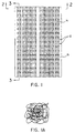
- Fig. 1 is an overhead view of the matting layer 11 of the laminate of the present invention which comprises randomly convoluted polymeric filaments.
- This matting layer can, for example be made in accordance with the method described in U.S. Patent No. 4,252,590 to A. Rasen, which is incorporated herein by reference, using a profile 4 which is the negative image of the profile 5 with square truncated upper surface 6 as depicted in Fig. 3 of the Rasen et al. patent.
- the matting 11 has formed in its body a plurality of truncated pyramidal cusps 12 which have sloping sides 13, as best seen in Figs. 2 and 3, and a generally flat floor, or apex, 14 at the point of truncation.
- the matting layer 11 of the laminate of the present invention also has at least one outwardly extending edge marginal portion 15 which is coplanar with the upper surface 16 of the matting layer 17 thereby forming bases for the cusps 12 and a coplanar wing 15, or flange, portion for the matting layer 11 (as best seen in Fig. 2).
- a pair of flanges 15 extend lengthwise of the layer 11.
- the laminate also comprises a fabric backing 18 bonded to the opposed bottom of the truncated pyramidal cusps and, thus, the matting layer itself.
- This fabric precludes the entry of insects, debris, and other unwanted elements when the laminate is used as a roof ridge vent construction.
- This fabric backing extends outwardly towards the "wing" portions 15 of the matting layer 11 and is bonded (preferably, heat bonded) to those outwardly extending, planar edge portions of the matting layer.
- the matting layer 11 previously described is constructed from a series of nylon 6 macrofilaments which have a diameter of from about 200 to about 1000 microns, preferably about 550 microns.
- These filaments form a planar mesh construction that takes the shape of the cusp structure, upon formation, as described above, wherein the cusps have a height of from about 0.25 inch to about 2 inches, preferably about 1 inch.
- the weight of the matting layer 11 can range about 30 to about 100 grams per square foot, preferably from about 50 to about 60 grams per square foot, with the preferred width of the laminate ranging from about 6 inches to about 15 inches, depending upon the roof shingle structure, but preferably will have a width of from about 10 to about 11 inches.
- a suitable fabric 18 to use in the present laminate is available under the trademark COLBACK from Akzo Nobel Nonwovens Inc. and is preferably a bi-component yarn of polyester and nylon.
- a most preferred fabric has the following specifications: weight - about 100 grams per square meter; thickness - about 0.5 mm; tenacity - about 44 pounds per inch; elongation - about 34%; and apparent opening size (AOS) - about 40.
- the matting layer has a hinge portion 19 which can be flexed to conform the product to the roof ridge of a roof as shown in Fig. 4.
- the laminate described herein can be appropriately fastened to a roof deck and shingle portion 20 of the roof, over the ridge vent 21, using nails 22 (which will, of course, be hidden from view by the overlapping shingles 23 once they are installed) to allow for appropriate air flow (as shown by the arrows in Fig. 4) through the vent and through the matting layer 11 of the laminate so that the needed ventilation of the building's attic or uppermost floor takes place.
- the cap shingles 23 are conventionally installed over the laminate with the "wing" portion of the laminate providing support.
- the laminate of the present has a number of advantages over previous laminate constructions known to persons of ordinary skill in the art.
- the novel pyramidal structures of the matting layer which make this product a "cuspated” rather than “non-cuspated” product, assist in affording the desired degree of noncompressibility to the product during such operations as the nailing of the structure to a roof of a building.
- the cuspated pyramidal structures do not impede the free flow of air through the present laminate since they are highly porous thereby distinguishing the present structure from the cuspated product sold under the trademark ROLL VENT 2. Since the fabric backing is supported on the exterior of the "cusps", it does not intrude into the inner structure of the present laminate so as to restrict the desired air flow through the laminate construction.
- having the smaller end of the novel pyramidal structures in contact with and directly attached to the backing material affords a surprising degree of desired stiffness as compared to not having such a portion of that structure attached to that backing.
- the fabric backing in the present laminate due to the presence of the outwardly extending, planar edge portion of that matting layer (a "wing" portion thereof) is more protected from direct sunlight when the normal cap shingle is installed over the laminate in the completed roof ridge vent.
- the fabric backing either may or may not be bonded to the surface of the outermost cusp at 18 in Fig. 4 and either may or may not lap over the top edge of the "wing" structure.
- the laminate of the present invention provides a support for the edge of the normal shingle used in the roof ridge vent construction by means of the "wing" thereby precluding drooping of the shingle during extreme conditions of heat which would tend to cut off part of the desired air flow through the construction.
- the hinge area formed in the laminate of the present invention allows for flexing of the laminate construction so that it can be bent over the ridge of the roof without damage to the construction.
- the preferred thermal bonding to the matting layer to the backing material avoids the presence of glue which, in extreme heat conditions, could undesirably liquefy compromising the bond between the matting layer and the backing.
- the bonding could be achieved by using glue or by using ultrasonic bonding, which some persons in the art consider as a form of thermal bonding.
- the fabric backing in a preferred embodiment, not only covers the exposed areas on each end of the vent (end cap), but also covers the slot area of the roof, thereby preventing intrusion of undesired insects, debris, and other items into the structure from within the attic.
- the laminate of the present invention can be easily rolled and can be easily adjusted or aligned once installation of the laminate in a roof construction has begun.
Abstract
Description
U.S. Patent No. 4,325,290 to C.K. Wolfert shows an early disclosure of the use of a non-cuspated nonwoven mat as the filter in a vent cap system.
U.S. Patent No 4,942,699 to L.J. Spinelli shows a vent construction comprising a non-cuspated matting of randomly convoluted polymeric filaments that are heat bonded to a porous sheet material layer. The subject matter shown in this patent has been sold by the assignee, Benjamin Obdyke Inc., under the trademark ROLL VENT for several years. More recently, the aforesaid Benjamin Obdyke Inc. has been selling a cuspated, more rigid product under the trademark ROLL VENT 2. U.S. Patent No. 5,122,095 to C.K. Wolfert illustrates an adjustable filtered roof ridge ventilator comprising a filter medium.
Another roof venting system is described in U.S. Patent No. 5,167,579 to M.J. Rotter which employs a non-cuspated, unitary mat of randomly aligned synthetic fibers which are opened and blended, randomly aligned by airflow, and joined by phenolic or latex binding agents and heat cured to produce an air permeable varying mesh.
U.S. Patent No. 5,425,672 to M.J. Rotter shows a roof vent of synthetic fiber matting which contains a grid of solid cores to insure the needed compression resilience of the construction.
- Fig. 1
- is an overhead view of the laminate of the present invention showing the arrangement of the downwardly facing, truncated pyramidal cusps formed in the matting layer;
- Fig. 1A
- is a view, in more detail than provided in Fig. 1, showing the construction of the matting layer used in the laminate of the present invention;
- Fig. 2
- is a cross-sectional view taken in the direction of the arrows joined to line 2-2 in Fig. 1;
- Fig. 3
- is a cross-sectional view taken in the direction of the arrows joined to line 3-3 in Fig. 1; and
- Fig. 4
- is a side cross-sectional view showing the laminate of the present invention in a roof vent construction.
The
In a preferred embodiment, the
A
The laminate of the present has a number of advantages over previous laminate constructions known to persons of ordinary skill in the art. The novel pyramidal structures of the matting layer, which make this product a "cuspated" rather than "non-cuspated" product, assist in affording the desired degree of noncompressibility to the product during such operations as the nailing of the structure to a roof of a building. The cuspated pyramidal structures do not impede the free flow of air through the present laminate since they are highly porous thereby distinguishing the present structure from the cuspated product sold under the
The fabric backing, in a preferred embodiment, not only covers the exposed areas on each end of the vent (end cap), but also covers the slot area of the roof, thereby preventing intrusion of undesired insects, debris, and other items into the structure from within the attic. The laminate of the present invention can be easily rolled and can be easily adjusted or aligned once installation of the laminate in a roof construction has begun.
Claims (15)
- A laminate which comprises (a) a matting layer of randomly convoluted polymeric filaments, a portion of the matting layer comprising a plurality of truncated pyramidal cusps, with at least one outwardly extending edge portion of the matting layer which is planar with one surface of the matting layer; and (b) a fabric backing bonded to the matting layer and extending outwardly and being bonded to the outwardly extending, planar edge portion of that matting layer.
- A laminate as claimed in claim 1 wherein the fabric backing (b) is in contact with the truncated portion of the pyramidal cusps.
- A laminate as claimed in any one of the claims 1-2 wherein two opposed edge portions of the matting layer are outwardly extending and planar.
- A laminate as claimed in any one of the claims 1-3 wherein two opposed edge portions of the matting layer are planar and the fabric backing (b) is in contact with the truncated portion of the pyramidal cusps.
- A laminate as claimed in any one of the claims 1-4 wherein two opposed edge portions of the matting layer are planar, the fabric backing (b) is in contact with the truncated portion of the pyramidal cusps, and two opposed edge portions of the matting layer are outwardly extending and planar.
- In combination, the laminate as claimed in any one of the claims 1-5 and the roof ridge vent area of a building.
- A roof vent for a roof ridge having an elongate slot, comprising: a continuous, indeterminate length, roll-form layer of randomly convoluted polymeric filaments; said layer having a planar portion and a plurality of lengthwise spaced apart cusps projecting from said planar portion; said cusps each having a base portion coplanar with said layer and an apex portion; and a fabric backing laminated across the apex portions of said cusps for confronting the slot when said roof vent is installed.
- The roof vent according to claim 7 wherein said layer has a pair of lengthwise extending coplanar edged margin flanges, and wherein said fabric backing is bonded to said coplanar edge margin flanges.
- The roof vent according to any one of the claims 7-8 wherein said fabric backing is bonded to preselected ones of said cusps at their apexes.
- The roof vent according to any one of the claims 7-9 wherein said cusps are of truncated shape having smaller apexes than bases.
- The roof vent according to any one of the claims 7-10 including a roof ridge defining an elongate vent slot confronting said fabric backing when said roof vent is installed.
- A roof vent for filtering air through an opening communicating between the interior and exterior of a building, said roof vent comprising: a layer of randomly convoluted polymeric filaments formed to extend over the opening, said layer defining a planar portion and a plurality of spaced apart cusps projecting from said planar portion, each of said cusps having a base portion coplanar with said layer and an apex portion; and a fabric backing laminated across said apex portions for overlying the opening when said roof vent is installed.
- The roof vent according to claim 12 wherein said backing is laminated to at least preselected ones of said apex portions.
- The roof vent according to any one of the claims 12-13 wherein said layer has a pair of oppositely extending coplanar edge margin flanges, and wherein said backing is bonded to said coplanar edge margin flanges.
- The roof vent according to any one of the claims 12-14 wherein said cusps are of truncated shapes having smaller apexes than bases.
Applications Claiming Priority (3)
| Application Number | Priority Date | Filing Date | Title |
|---|---|---|---|
| US08/852,650 US5960595A (en) | 1997-05-07 | 1997-05-07 | Laminate comprising matting layer and roof construction containing the same |
| US850312 | 1997-05-07 | ||
| US852650 | 1997-05-07 |
Publications (2)
| Publication Number | Publication Date |
|---|---|
| EP0876906A2 true EP0876906A2 (en) | 1998-11-11 |
| EP0876906A3 EP0876906A3 (en) | 2001-11-21 |
Family
ID=25313888
Family Applications (1)
| Application Number | Title | Priority Date | Filing Date |
|---|---|---|---|
| EP98201397A Withdrawn EP0876906A3 (en) | 1997-05-07 | 1998-04-29 | Laminate comprising matting layer and roof construction containing the same |
Country Status (3)
| Country | Link |
|---|---|
| US (1) | US5960595A (en) |
| EP (1) | EP0876906A3 (en) |
| CA (1) | CA2236487C (en) |
Cited By (1)
| Publication number | Priority date | Publication date | Assignee | Title |
|---|---|---|---|---|
| EP3018264A1 (en) * | 2014-11-05 | 2016-05-11 | Wischemann Kunststoff GmbH | Plate of a laminar structure storing water |
Families Citing this family (50)
| Publication number | Priority date | Publication date | Assignee | Title |
|---|---|---|---|---|
| US6804922B1 (en) * | 1998-06-03 | 2004-10-19 | Construction Research & Technology Gmbh | Integral composite building material and uses therefor |
| CA2294412A1 (en) | 1999-01-11 | 2000-07-11 | Benjamin Obdyke Incorporated | Adjustable roof ridge vent |
| US6343985B1 (en) | 2000-01-14 | 2002-02-05 | Blocksom & Co. | Roof ridge ventilator system of natural fiber matting |
| US6298613B1 (en) | 2000-02-10 | 2001-10-09 | Benjamin Obdyke, Inc. | Roof ridge vent having a reinforced nail line |
| US6786013B2 (en) | 2000-06-14 | 2004-09-07 | Benjamin Obdyke Incorporated | Building structure and spacer used therein |
| US6745531B1 (en) | 2000-07-31 | 2004-06-08 | Construction Research & Technology Gmbh | Pressure equalized compartment for exterior insulation and finish system |
| US6594965B2 (en) | 2001-08-21 | 2003-07-22 | Benjamin Obdyke Incorporated | Spacer for providing drainage passageways within building structures |
| US6981916B2 (en) * | 2003-10-10 | 2006-01-03 | Benjamin Obdyke, Inc. | Roof ridge vent |
| US7786026B2 (en) * | 2003-12-19 | 2010-08-31 | Saint-Gobain Technical Fabrics America, Inc. | Enhanced thickness fabric and method of making same |
| US7625827B2 (en) * | 2003-12-19 | 2009-12-01 | Basf Construction Chemicals, Llc | Exterior finishing system and building wall containing a corrosion-resistant enhanced thickness fabric and method of constructing same |
| US7182688B2 (en) * | 2003-12-22 | 2007-02-27 | Benjamin Obdyke Incorporated | Rollable roof ridge vent having baffles |
| US7604536B2 (en) * | 2004-10-08 | 2009-10-20 | Benjamin Obdyke Incorporated | Roof ridge vent having honeycomb or like ventilation material |
| US20060101758A1 (en) * | 2004-11-18 | 2006-05-18 | Egan William F | Composite building material |
| US20070094966A1 (en) | 2004-11-23 | 2007-05-03 | Certainteed Corporation | Insulation Batt Having Integral Baffle Vent |
| US7644545B2 (en) * | 2004-11-23 | 2010-01-12 | Certainteed Corporation | Insulation batt having integral baffle vent |
| CA2530264A1 (en) * | 2004-12-21 | 2006-06-21 | Benjamin Obdyke Incorporated | Roof ridge vent having an integral covering and method of installing a ridge vent |
| CA2499557C (en) * | 2005-03-07 | 2013-01-08 | Canplas Industries Ltd. | Ridge vent apparatus |
| US20060245830A1 (en) * | 2005-04-27 | 2006-11-02 | Jon Woolstencroft | Reinforcement membrane and methods of manufacture and use |
| US7393273B2 (en) * | 2005-09-07 | 2008-07-01 | Benjamin Obdyke, Inc. | Roof ridge vent, assembly and method of installation |
| US20070234650A1 (en) * | 2006-03-27 | 2007-10-11 | Benjamin Obdyke Incorporated | Vented Soffit Assembly and Method of Installation |
| US20080034685A1 (en) * | 2006-04-12 | 2008-02-14 | Ogletree Ronald K | Roof Ventilation Device |
| US20080028689A1 (en) * | 2006-08-04 | 2008-02-07 | Joseph Sporta | Method and assembly for preventing the production of windborne debris |
| US7607270B2 (en) * | 2006-08-16 | 2009-10-27 | Benjamin Obdyke Incorporated | Drainage-promoting wrap for an exterior wall or roof of a building |
| US20080220714A1 (en) * | 2006-10-20 | 2008-09-11 | Benjamin Obdyke Incorporated | Ember and Fire-Resistant Vent |
| US20080148669A1 (en) * | 2006-12-22 | 2008-06-26 | Benjamin Obdyke Incorporated | Patch Assembly for Roof Decking and Method |
| US7814715B2 (en) * | 2007-07-23 | 2010-10-19 | Benjamin Obdyke Incorporated | Rollable roof ridge vent |
| MX2011002476A (en) * | 2008-09-05 | 2011-07-28 | Colbond Bv | Thermal barrier in building structures. |
| US8146310B2 (en) * | 2009-03-11 | 2012-04-03 | Keene Building Products Co., Inc. | Noise control flooring system |
| US8528286B2 (en) * | 2009-11-10 | 2013-09-10 | Keene Building Products Co., Inc. | Sound control mat |
| US9200453B2 (en) * | 2010-02-04 | 2015-12-01 | Benjamin Obdyke Incorporated | Ridge vent mat and roof ridge assembly |
| US8574045B2 (en) * | 2010-12-17 | 2013-11-05 | Dina Warner | Frost-free vent assembly |
| CA2753482C (en) | 2011-09-22 | 2018-03-06 | Canplas Industries Ltd. | Vent for venting a building enclosure |
| US10852016B2 (en) | 2011-11-07 | 2020-12-01 | Snowventco Limited | Roof vent |
| US11585545B2 (en) | 2011-11-07 | 2023-02-21 | Snowventco Limited | Ridge vent |
| US10018368B2 (en) * | 2011-11-07 | 2018-07-10 | Snowventco Ltd. | Snow proof roof vent |
| US9457304B2 (en) * | 2011-11-07 | 2016-10-04 | Snowventco Ltd. | Roof vent |
| US9428916B2 (en) | 2011-12-27 | 2016-08-30 | Building Materials Investment Corporation | Mesh vent with varying density or integral moisture barrier |
| US8555560B2 (en) | 2012-03-07 | 2013-10-15 | Quality Edge, Inc. | Roofing corbel |
| US20140179220A1 (en) | 2012-12-20 | 2014-06-26 | Building Materials Investment Corporation | Contoured Mesh Ridge Vents |
| US11485112B2 (en) | 2013-07-22 | 2022-11-01 | VaproShield, LLC | Building membrane with porous pressure sensitive adhesive |
| US11186985B2 (en) | 2013-07-22 | 2021-11-30 | VaproShield, LLC | Vapor permeable, water resistive, air barrier polyester membrane having a polyacrylic coating with porous pressure sensitive adhesive added to the rear surface of the membrane |
| US10415253B2 (en) | 2014-05-01 | 2019-09-17 | Owens Corning Intellectual Capital, Llc | Ridge vent |
| US10125489B2 (en) | 2014-07-01 | 2018-11-13 | VaproShield, LLC | Self adhering weather resistant vapor permeable air barrier membrane with rain plane matrix |
| US9783980B2 (en) | 2014-07-01 | 2017-10-10 | VaproShield, LLC | Building membrane with drainage matrix and horizontal adhesive portions |
| EA201790161A1 (en) | 2014-08-05 | 2017-11-30 | Солидиа Текнолоджиз, Инк. | METHOD AND DEVICE FOR CURING COMPOSITE MATERIAL BY REGULATING RESTRICTIVE SPEED STEPS IN WATER REMOVAL |
| CA2915610C (en) * | 2014-12-17 | 2021-03-30 | James R. Keene | Roof ventilation system and method |
| US10508451B2 (en) | 2016-06-01 | 2019-12-17 | Martin J. Rotter | Hip and ridge vent |
| US10655341B2 (en) * | 2018-06-14 | 2020-05-19 | Low & Bonar Inc. | Flooring mat with entangled filament structure |
| US11525265B2 (en) | 2018-09-18 | 2022-12-13 | VaproShield, LLC | Permeable water resistive roof underlayment |
| US11512473B2 (en) | 2018-12-13 | 2022-11-29 | Vaproshield Llc | Permeable water-resistive sloped roof underlayment/air barrier |
Citations (6)
| Publication number | Priority date | Publication date | Assignee | Title |
|---|---|---|---|---|
| US3673057A (en) * | 1970-07-22 | 1972-06-27 | Fmc Corp | Cellular structures |
| US3955019A (en) * | 1971-11-29 | 1976-05-04 | Donald George Keith | Cuspated sheet forming |
| US3963813A (en) * | 1974-12-24 | 1976-06-15 | The United States Of America As Represented By The Secretary Of The Navy | Cuspated sheet forming |
| US4252590A (en) * | 1975-07-09 | 1981-02-24 | Akzona Incorporated | Low density matting and process |
| EP0668153A2 (en) * | 1994-02-17 | 1995-08-23 | Takashimaya Nippatsu Kogyo Co. Ltd. | Flexible lamnated surface material and method of producing the same |
| US5673521A (en) * | 1994-12-16 | 1997-10-07 | Benjamin Obdyke Incorporated | Rolled roof vent and method of making same |
Family Cites Families (13)
| Publication number | Priority date | Publication date | Assignee | Title |
|---|---|---|---|---|
| DE1778026C3 (en) * | 1968-03-21 | 1981-06-11 | Enka Ag, 5600 Wuppertal | Upholstery material made from a large number of loops and intersecting synthetic filaments |
| US3691004A (en) * | 1969-11-21 | 1972-09-12 | Akzona Inc | Matting of melt-spun amorphous polymer filaments and process |
| US4212692A (en) * | 1977-05-06 | 1980-07-15 | Akzona Incorporated | Matting article with process and apparatus for its production |
| DE2845700A1 (en) * | 1978-10-20 | 1980-04-30 | Icopal Baustoffe Gmbh | ROOF COVER FILM, PARTICULARLY ROOF PAPER |
| US4325290A (en) * | 1980-10-06 | 1982-04-20 | Air Vent, Inc. | Filtered roof ridge ventilator |
| US4538388A (en) * | 1983-02-07 | 1985-09-03 | Armstrong World Industries, Inc. | Positively vented flat roof system |
| US4942699A (en) * | 1987-11-25 | 1990-07-24 | Benjamin Obdyke Incorporated | Venting of roofs |
| US5099627A (en) * | 1990-09-28 | 1992-03-31 | Benjamin Obdyke Incorporated | Ventilated roof construction and method |
| US5122095A (en) * | 1991-03-04 | 1992-06-16 | Air Vent, Inc. | Adjustable filtered roof ridge ventilator |
| US5167579A (en) * | 1991-08-15 | 1992-12-01 | Rotter Martin J | Roof vent of synthetic fiber matting |
| US5352154A (en) * | 1993-11-01 | 1994-10-04 | Martin Rotter | Metal roof ventilation system |
| US5561953A (en) * | 1994-12-01 | 1996-10-08 | Rotter; Martin J. | Contoured ventilation system for metal roofs |
| US5651734A (en) * | 1995-12-11 | 1997-07-29 | Liberty Diversified Industries, Inc. | Ridge cap roof ventilator applied in roll form and method of use |
-
1997
- 1997-05-07 US US08/852,650 patent/US5960595A/en not_active Expired - Lifetime
-
1998
- 1998-04-29 EP EP98201397A patent/EP0876906A3/en not_active Withdrawn
- 1998-05-01 CA CA002236487A patent/CA2236487C/en not_active Expired - Lifetime
Patent Citations (6)
| Publication number | Priority date | Publication date | Assignee | Title |
|---|---|---|---|---|
| US3673057A (en) * | 1970-07-22 | 1972-06-27 | Fmc Corp | Cellular structures |
| US3955019A (en) * | 1971-11-29 | 1976-05-04 | Donald George Keith | Cuspated sheet forming |
| US3963813A (en) * | 1974-12-24 | 1976-06-15 | The United States Of America As Represented By The Secretary Of The Navy | Cuspated sheet forming |
| US4252590A (en) * | 1975-07-09 | 1981-02-24 | Akzona Incorporated | Low density matting and process |
| EP0668153A2 (en) * | 1994-02-17 | 1995-08-23 | Takashimaya Nippatsu Kogyo Co. Ltd. | Flexible lamnated surface material and method of producing the same |
| US5673521A (en) * | 1994-12-16 | 1997-10-07 | Benjamin Obdyke Incorporated | Rolled roof vent and method of making same |
Cited By (1)
| Publication number | Priority date | Publication date | Assignee | Title |
|---|---|---|---|---|
| EP3018264A1 (en) * | 2014-11-05 | 2016-05-11 | Wischemann Kunststoff GmbH | Plate of a laminar structure storing water |
Also Published As
| Publication number | Publication date |
|---|---|
| CA2236487A1 (en) | 1998-11-07 |
| CA2236487C (en) | 2007-04-10 |
| US5960595A (en) | 1999-10-05 |
| EP0876906A3 (en) | 2001-11-21 |
Similar Documents
| Publication | Publication Date | Title |
|---|---|---|
| US5960595A (en) | Laminate comprising matting layer and roof construction containing the same | |
| US4942699A (en) | Venting of roofs | |
| US10815668B2 (en) | Roof ridge vent system | |
| CA2113354C (en) | Roof vent of synthetic fiber matting | |
| CA2289769C (en) | Improved roof closure vent system | |
| US6145255A (en) | Soffit vent | |
| CA1188866A (en) | Roof ridge ventilator | |
| US5002816A (en) | Sealing strip for a ridging | |
| US5826383A (en) | Roof closure vent system | |
| US5704834A (en) | Moisture resistant roof vent | |
| US5195290A (en) | Laminar roofing product | |
| EP1186728B1 (en) | Precipitation resistant ridge vent | |
| US4876950A (en) | Roof ventilator | |
| DE4001766C2 (en) | Ridge or ridge ventilation element for pan roofs | |
| CA2500984C (en) | Contoured ventilation system for tile roofs | |
| US5238450A (en) | Air-permeable barrier for soffit vent | |
| CA2729441C (en) | Ridge vent and roof ridge assembly | |
| US6491581B1 (en) | Roof ventilator and filter | |
| JP2008522059A (en) | Baffle vent for S tile building | |
| US10113760B2 (en) | Ventilation system for contoured roofs | |
| US10428530B2 (en) | Entangled mesh roof vent with integrated external baffle | |
| WO2004031508A2 (en) | Roof ridge vent with water barrier | |
| US11306930B2 (en) | Ridge vent for use on a roof ridge | |
| JP3972981B2 (en) | Ventilation stop | |
| JPH07109797A (en) | Roof ventilation structure by mat made of synthetic fiber |
Legal Events
| Date | Code | Title | Description |
|---|---|---|---|
| PUAI | Public reference made under article 153(3) epc to a published international application that has entered the european phase |
Free format text: ORIGINAL CODE: 0009012 |
|
| AK | Designated contracting states |
Kind code of ref document: A2 Designated state(s): AT BE CH CY DE DK ES FI FR GB GR IE IT LI LU MC NL PT SE |
|
| AX | Request for extension of the european patent |
Free format text: AL;LT;LV;MK;RO;SI |
|
| RAP1 | Party data changed (applicant data changed or rights of an application transferred) |
Owner name: BENJAMIN OBDYKE INCORPORATED Owner name: COLBOND GEOSYNTHETICS GMBH |
|
| PUAL | Search report despatched |
Free format text: ORIGINAL CODE: 0009013 |
|
| AK | Designated contracting states |
Kind code of ref document: A3 Designated state(s): AT BE CH CY DE DK ES FI FR GB GR IE IT LI LU MC NL PT SE |
|
| AX | Request for extension of the european patent |
Free format text: AL;LT;LV;MK;RO;SI |
|
| AKX | Designation fees paid |
Free format text: AT BE CH CY DE DK ES FI FR GB GR IE IT LI LU MC NL PT SE |
|
| STAA | Information on the status of an ep patent application or granted ep patent |
Free format text: STATUS: THE APPLICATION IS DEEMED TO BE WITHDRAWN |
|
| 18D | Application deemed to be withdrawn |
Effective date: 20020522 |