EP0875810B1 - Verfahren und Vorrichtung zum Überwachen einer Anlage mit mehreren Funktionseinheiten - Google Patents
Verfahren und Vorrichtung zum Überwachen einer Anlage mit mehreren Funktionseinheiten Download PDFInfo
- Publication number
- EP0875810B1 EP0875810B1 EP98107462A EP98107462A EP0875810B1 EP 0875810 B1 EP0875810 B1 EP 0875810B1 EP 98107462 A EP98107462 A EP 98107462A EP 98107462 A EP98107462 A EP 98107462A EP 0875810 B1 EP0875810 B1 EP 0875810B1
- Authority
- EP
- European Patent Office
- Prior art keywords
- safety
- safety devices
- devices
- inputs
- monitoring
- Prior art date
- Legal status (The legal status is an assumption and is not a legal conclusion. Google has not performed a legal analysis and makes no representation as to the accuracy of the status listed.)
- Expired - Lifetime
Links
Images
Classifications
-
- G—PHYSICS
- G05—CONTROLLING; REGULATING
- G05B—CONTROL OR REGULATING SYSTEMS IN GENERAL; FUNCTIONAL ELEMENTS OF SUCH SYSTEMS; MONITORING OR TESTING ARRANGEMENTS FOR SUCH SYSTEMS OR ELEMENTS
- G05B19/00—Programme-control systems
- G05B19/02—Programme-control systems electric
- G05B19/418—Total factory control, i.e. centrally controlling a plurality of machines, e.g. direct or distributed numerical control [DNC], flexible manufacturing systems [FMS], integrated manufacturing systems [IMS], computer integrated manufacturing [CIM]
-
- G—PHYSICS
- G05—CONTROLLING; REGULATING
- G05B—CONTROL OR REGULATING SYSTEMS IN GENERAL; FUNCTIONAL ELEMENTS OF SUCH SYSTEMS; MONITORING OR TESTING ARRANGEMENTS FOR SUCH SYSTEMS OR ELEMENTS
- G05B19/00—Programme-control systems
- G05B19/02—Programme-control systems electric
- G05B19/18—Numerical control [NC], i.e. automatically operating machines, in particular machine tools, e.g. in a manufacturing environment, so as to execute positioning, movement or co-ordinated operations by means of programme data in numerical form
- G05B19/406—Numerical control [NC], i.e. automatically operating machines, in particular machine tools, e.g. in a manufacturing environment, so as to execute positioning, movement or co-ordinated operations by means of programme data in numerical form characterised by monitoring or safety
-
- G—PHYSICS
- G05—CONTROLLING; REGULATING
- G05B—CONTROL OR REGULATING SYSTEMS IN GENERAL; FUNCTIONAL ELEMENTS OF SUCH SYSTEMS; MONITORING OR TESTING ARRANGEMENTS FOR SUCH SYSTEMS OR ELEMENTS
- G05B23/00—Testing or monitoring of control systems or parts thereof
-
- Y—GENERAL TAGGING OF NEW TECHNOLOGICAL DEVELOPMENTS; GENERAL TAGGING OF CROSS-SECTIONAL TECHNOLOGIES SPANNING OVER SEVERAL SECTIONS OF THE IPC; TECHNICAL SUBJECTS COVERED BY FORMER USPC CROSS-REFERENCE ART COLLECTIONS [XRACs] AND DIGESTS
- Y02—TECHNOLOGIES OR APPLICATIONS FOR MITIGATION OR ADAPTATION AGAINST CLIMATE CHANGE
- Y02P—CLIMATE CHANGE MITIGATION TECHNOLOGIES IN THE PRODUCTION OR PROCESSING OF GOODS
- Y02P90/00—Enabling technologies with a potential contribution to greenhouse gas [GHG] emissions mitigation
- Y02P90/02—Total factory control, e.g. smart factories, flexible manufacturing systems [FMS] or integrated manufacturing systems [IMS]
Definitions
- the invention relates to a method according to the preamble of claim 1 and a device according to the preamble of claim 7 for monitoring a system with several Functional units, such as those of a manufacturing plant.
- a machine or a robot In a plant, such as a manufacturing plant, of which the Invention starts, it can be one or more of each other trade associated machines, such as robots.
- a machine or a robot consists of several different functional units, such as the power section (Power module), a control unit, an operating unit u.a .. In a plant that is assumed to be several such machines with the functional units mentioned work together and be interconnected.
- Farther peripherals, such as rails, may be present where the machines, such as robots, are moved or moved Portal that shows the machines or robots along one to be machined "Workpiece" like a ship.
- WO 95/16943 describes a method for monitoring safety-relevant Features of a device known at the two microcomputer systems with each other via a data bus are connected.
- a processor fulfills a master function, while the other works as a slave. That with it connected time-shifted and task-separated work when comparing the processors in particular the distinction from sporadic interferences real operational errors.
- WO 95/17706 shows a method in which two or more dedicated, i.e. a computer assigned to a functional unit control the process simultaneously, and real-time data that present the actual state of selected variables, simultaneously with an alphanumeric representation a source code statement based on this variable one Display.
- EP 400 624 shows a distributed control device, at assigned to the engine control units in individual engines are and continue to be optical monitoring and display available.
- the invention has for its object a method and to create a device by means of which simple, clearly an inherent increase in security with complex systems as outlined above was achieved.
- the stated object is achieved by a method of the type mentioned with the features of the claim 1 and a device of the aforementioned Art solved with the features of claim 7.
- the invention provides a distributed security logic, where every safety device has all the necessary Has security functions. This is one high-resolution diagnosis possible.
- the safety devices are connected or communicate with each other with each other so that they also monitor each other can and a safety device the failure of a recognizes others and thus a safety-relevant signal can output to actuate an actuator.
- the safety devices a controller core and a Have interface wiring. This allows the Safety devices very simple and clear be constructed.
- the safety devices communicate serially with each other or that the safety devices are in series with each other are connected.
- the serial connection makes a parallel one No wiring required. Necessary cable cross sections can be reduced, especially for portable Devices, such as operating or programming handsets, extremely is advantageous.
- the safety devices using a ring protocol communicate with each other or that the safety devices are connected in a ring. So that is the entire safety device in a simple manner expandable. For example, if the system has more Receives functional units, so the associated safety devices easily integrated in a simple manner become. This makes it simple and clear Adaptability to different systems guaranteed.
- the addressing can be done physically Placement on the bus. A sure reaction is too immediately accessible when expanding the ring protocol.
- each safety device at least has two microprocessors. More preferred Refinements provide that every security device Has diagnostic inputs, in particular the diagnostic inputs with test switching cycles of safety-relevant Inputs are synchronized or the safety devices ongoing diagnosis of the functional units assigned to them and thus carry out the system. hereby can signalers that have a safety-related signal delivered, be localized. Furthermore, can permanent monitoring and diagnosis of the entire system be made.
- microprocessors contained in the safety devices cyclically your processor image and the calculated from it Check result and / or content of memories, in particular the correct connection and function is checked by signal inputs and signal transmitters. Due to the redundant design of the safety devices in the manner outlined above Microprocessors each other and the surrounding Check the hardware cyclically, at the same time the expiring Program can be checked for consistency. The The content of the processors is compared with one Ring protocol over the entire ring.
- each safety device at least has a safety-related output and / or that each safety device has several safety-relevant ones Has inputs.
- Both the entire security structure becomes simple and Particularly inexpensive if planned for further training is that the safety devices are identical to each other are formed, preferably also in the Basic software integrated into identical safety devices is identical and adjustments only about Soft blocks or switches are made.
- the inventive method and the inventive Solution have significant advantages.
- the ring structure the entire monitoring device is only closed, if all functional units and assigned to them individual safety devices in operation are located. Communication is interrupted when one Safety device shows a malfunction; at a such an ongoing disturbance is switched off and the entire system enters a safe state.
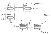
- a device is used for monitoring a plant A, such as a manufacturing plant; such has, for example, a power unit 1 which Power electronics and the mechanical elements of a Machine or a robot.
- the power unit 1 is assigned a control unit, which Signal electronics for controlling the power unit 1 contains and as a pure hardware circuit or in the desired Gradation with software elements up to one pure computer control, can be trained.
- a robot is power unit 1 and control unit 2 usually physically and spatially separated designed.
- a system from which the invention is based can also have an operating unit 3, for example can be a handheld programming device that specific case for programming a robot like the one Control unit 2 can serve and in such a case also spatially and physically separate from this is trained.
- peripherals 4, 5 have, such as a moving device for the power unit (Power Module) 1 or for example in shipbuilding a portal on which several performance units 1 are arranged.
- Power Module Power Module
- a safety device 6 has (at least) two microcontrollers. These have sufficient integrated RAMs or ROMs and at least one serial Terminal (point). So the dual channel of the Safety circles up to the evaluation be preserved. The two channels of the redundant system are constantly compared. Depending on the use is one different interface wiring provided.
- the safety devices 6.1-6.5 are above incoming and forwarding interfaces or lines 7, 8 in connection. The connection is preferred still in a ring structure with outgoing and return lines 7, 8 formed.
- a safety device 6 has in addition to the serial connections or lines 7, 8 for Connection with the other security devices safety-relevant inputs 10-14 which are connected to the respective functional unit and individual controls the same are connected and more security-relevant for reading Serve signals.
- safety related Inputs either initiate a stop or are a condition for such a stop.
- the inputs 11-14 are double, so each microcontroller via an independent input with identical function features. Inputs without a safety function can also be used be provided. These are also called diagnostic inputs designated and have different on both controllers Importance. All safety-relevant inputs 11-14 are evaluated in parallel by both microcontrollers. So an entrance with an approval button, another with an emergency stop button and another with a selection button for test or automatic mode connected his.
- the operator protection input - locking (for techn. Protective measures) - only sets the safety cell itself quiet.
- the area is under the safety cell understood that drive through dangerous by a kinematics can be. For a robot cell this is e.g. the working area of the robot limited by protective fences itself as well as the additional axles, the dangerous Can perform movements.
- the pending operator protection signal is synonymous with the closed Protective fence of the security cell.
- the input 13 for test / automatic is a qualifying signal.
- test mode operator protection is switched off and the approval buttons are active.
- Operator protection is active in the automatic mode, and the consent buttons are not queried.
- the safety cell can either be in the test or automatic mode. Neither of the two operating modes are possible at the same time as neither operating mode.
- the closed-circuit principle is difficult to adhere to here because both settings are active settings. It is therefore advisable to use counter-parallel levels.
- the result is that the signal is read in by the ⁇ controllers once as automatic and once as / automatic .
- the term Test is used instead of the name / automatic .
- Safety-relevant outputs are those whose proper function for switching off the system energy is imperative.
- the safety-relevant outputs include the control for the network protection of the drives by the drives one signal. This output is available on every safety device and is safe.
- the emergency stop exit has the task of making a local emergency stop request into the emergency loop of a complete system grind. To get potential-free contacts, becomes the node with a safe relay combination fitted.
- Operator protection means facilities for Protection of the operator include protective fences, their Monitoring and depending on the operating mode also the Enabling switch. All outputs are in the node such facilities summarized.
- the operator protection output has the task of violating operator protection also effective for plant components involved do. To get potential-free contacts, a safe relay combination is connected to the nodes become.
- Informal or control inputs 17 are those that are necessary for the correct operation of the robot. These inputs are not safety-relevant and can can be used freely. They just provide information available for diagnostic purposes. The inputs are synchronized with the test switching cycles of the safety-relevant Signals. This also enables linked emergency stop buttons between the contacts.
- the "Activate drives” signal is an impulse that the Actuators should switch on as long as there is no safety requirement speaks against it. This signal must not be kept constantly active.
- Actuators enable AF
- the "drives enable” signal has the task of Switch off drives by removing or switching on to prevent.
- a local emergency stop or operator protection loop can tapped with these inputs between contacts to provide information about to get the location of the security request.
- Informal exits are the ones that are spent to represent the status of the security network. Informal outputs can go to a register interface be summarized. When connecting one Control computer, in which no safety-relevant Actuators are available, can also be safety-related Outputs can be used for information purposes.
- the emergency stop information has the task of reporting a local emergency stop request to a controller or signal lamp.
- This signal is an OR operation of all emergency stop conditions with the exception of the signal: external emergency stop request .
- the error signal provides information as to whether it is within the KU-SIBA network has made a mistake that leads to Shutdown has resulted.
- a safety device in the control unit 2 there are all information and states of the safety circuit the control software.
- an exit will be assigned an emergency stop by one trigger such in the control unit 2.
- a safety device 6.1 in an operating unit 3 is mainly the carrier of signaling devices for emergency stop, Operating mode selection and switching the drives on and off.
- a display can be made via control software and a display respectively.
- Safety devices 6.4 and 6.5 in the periphery 4, 5 can drive energy for integrated in a protection circuit Operate the servo switch and signal transmitter such as Extended light curtains and additional emergency stop button Integrate kinematics into the protective circuit.
- the display can be an identical security device can also be integrated into corresponding control panels.
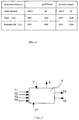
- Fig. 3 are the operating states of the safety devices according to the invention shown.
- Operator protection can be open or closed.
- An consent key can be pressed (yes) or not be actuated (no). It can be an automatic or test mode be chosen. In automatic mode is how from the list, operation is only possible if operator protection is closed. If "test” is selected operation with operator protection open and closed possible, but only if the consent button is pressed at the same time is operated.
- the operating states can with regard to further inputs depending on the purpose of use.
- the information channel used for the comparison is the same serial channel that is used for the Communication between security devices is used.
- a comparison is made during ongoing process communication: One step corresponds to the amount of data one Microcontroller. A sliding step, it depends on the position of the microcontroller of the safety device the first or the last one per communication, is for provided the comparison. In this step it will Input and output image with that of the parallel Microcontrollers in the same security device compared.
- each microcontroller transmits own process data.
- the second microcontroller a safety device can already to compare.
- the first microcontroller The process image of the previous microcontroller is first noted. He makes the comparison after the second Sliding step through.
- the VF counter of this microcontroller therefore applies to the one previously arranged in the safety circuit Security kernel.
- a link is made as the actual one Function of the Schierheit Vietnamese: On the one hand, the Inputs of each individual safety device own result formed; second, the results the other security devices before upgrading taken into account in the local result. There are two ways to determine the output results: The entire process image can be used for communication be exchanged and thus in each of the total emergency parallel, but linked in different order become. An execution command can be sent. In all safety devices link this command their results and there will be all exits after this Command switched.
- the emergency stop function can be used by various signal generators to be triggered. All connected signal transmitters are connected via two channels. When releasing the emergency stop lock can be infinite simultaneity between the channels.
- the emergency stop has different operating modes Reactions.
- the shutdown of the network is in automatic mode delayed and safe.
- the initiated emergency stop is from recognized by the control system and an emergency stop ramp is activated immediately hazards. With this stop ramp the remains Robots on the programmed path. The robot comes in a calculated point to a standstill.
- Communication between security devices is serial and goes through both microcontrollers through so that each microcontroller is able to the other via the communication ring Provide process image for comparison.
- the Communication is used to compare the channels in two-channel Inputs and for deterministic updating of the output image on the entire bus.
- each Communication takes place in sliding steps.
- a step corresponds to the data volume of a microcontroller. On Sliding step, it's the first or the last pro Communication is intended for comparison. All other sliding steps are used to map the overall process of the network in the individual security device to investigate. Only process images are used taken over by others, which of their two Controllers were immediately transferred.
Description
- Fig. 1
- einen schematischen Aufbau einer erfindungsgemäßen Sicherheits-Vorrichtung an einer zu überwachenden Anlage;
- Fig. 2
- eine schematische Darstellung einer Sicherheitseinrichtung der erfindungsgemäßen Vorrichtung; und
- Fig. 3
- ein Diagramm der durch die Erfindung gewährleisteten Betriebszustände der erfindungsgemäßen Vorrichtung.
Claims (17)
- Verfahren zum Überwachen einer Anlage (A) mit mehreren Funktionseinheiten (1-5), wie solchen einer Fertigungsanlage, wobei mindestens eine jeder Funktionseinheit (1-5) jeweils eigene und dieser individuell zugeordnete zweikanalige, in sich redundante Sicherheitseinrichtung (6; 6.1-6.5) jeweils ihre Funktionseinheit (1-5) und gegebenenfalls weitere dieser zugeordnete Einrichtungen laufend überprüft, wobei bei einer Fehlfunktion mindestens einer Funktionseinheit (1-5) oder Sicherheitseinrichtung (6; 6.1-6.5) mindestens ein sicherheitsrelevantes Stellglied betätigt wird, dadurch gekennzeichnet, dass auch die unterschiedlichen Funktionseinheiten (1-5) zugeordneten Sicherheitseinrichtungen (6; 6.1-6.5) einander laufend überwachen und über ihren Überprüfungsstand unterrichten und dass die sicherheitsrelevanten Eingänge (11-14) der beiden Kanäle jeder der Sicherheitseinrichtungen (6; 6.1-6.5) zeitlich parallel ausgewertet werden.
- Verfahren nach Anspruch 1, dadurch gekennzeichnet, daß die Sicherheitseinrichtungen seriell miteinander kommunizieren.
- Verfahren nach Anspruch 1 oder 2, dadurch gekennzeichnet, daß die Sicherheitseinrichtungen mittels eines Ringprotokolls miteinander kommunizieren.
- Verfahren nach einem der vorangehenden Ansprüche, dadurch gekennzeichnet, daß die Sicherheitseinrichtungen laufend eine Diagnose der ihnen zugeordneten Funktionseinheiten und damit der Anlage durchführen.
- Verfahren nach einem der Ansprüche 1 bis 4, dadurch gekennzeichnet, daß in den Sicherheitseinrichtungen enthaltene Mikroprozessoren zyklisch ihr Prozessorbild und das daraus kalkulierte Ergebnis und/oder den Inhalt von Speichern überprüfen.
- Verfahren nach einem der vorangehenden Ansprüche, dadurch gekennzeichnet, daß der korrekte Anschluß und die Funktion von Signaleingängen und Signalgebern überprüft wird.
- Vorrichtung zum Überwachen einer Anlage (A) mit mehreren Funktionseinheiten (1-5), wie einer Fertigungsanlage, wobei jeder Funktionseinheit (1-5) jeweils mindestens eine eigene zweikanalige, in sich redundante Einrichtung (6; 6.1-6.5) als die Funktionseinheiten (1-5) überwachende Sicherheitseinrichtungen (6; 6.1-6.5) zugeordnet ist, wobei bei einer Fehlfunktion mindestens einer Funktionseinheit (1-5) oder Sicherheitseinrichtung (6; 6.1-6.5) mindestens ein sicherheitsrelevantes Stellglied betätigbar ist, dadurch gekennzeichnet, dass auch die unterschiedlichen Funktionseinheiten zugeordneten Sicherheitseinrichtungen (6; 6.1-6.5) zur laufenden gegenseitigen Überwachung und Unterrichtung über ihren Überprüfungszustand miteinander verbunden sind und dass die sicherheitsrelevanten Eingänge (11-14) jeder der Kanäle der Sicherheitseinrichtungen (6; 6.1-6.5) zeitlich parallel auswertbar sind.
- Vorrichtung nach Anspruch 7, dadurch gekennzeichnet, daß die Sicherheitseinrichtungen (6; 6.1-6.5) einen Controller-Kern und eine Schnittstellenbeschaltung aufweisen.
- Vorrichtung nach Anspruch 7 oder 8, dadurch gekennzeichnet, daß die Sicherheitseinrichtungen (6; 6.1-6.5) seriell miteinander verbunden sind.
- Vorrichtung nach einem der Ansprüche 7 bis 9, dadurch gekennzeichnet, daß die Sicherheitseinrichtungen (6; 6.1-6.5) in einem Ring miteinander verbunden sind.
- Vorrichtung nach einem der Ansprüche 7 bis 10, dadurch gekennzeichnet, daß jede Sicherheitseinrichtung mindestens einen Mikroprozessor aufweist.
- Vorrichtung nach Anspruch 11, dadurch gekennzeichnet, daß jede Sicherheitseinrichtung (6; 6.1-6.5) mindestens zwei Mikroprozessoren aufweist.
- Vorrichtung nach einem der Ansprüche 7 bis 12, dadurch gekennzeichnet, daß jede Sicherheitseinrichtung mindestens einen sicherheitsrelevanten Ausgang (15, 16) aufweist.
- Vorrichtung nach einem der Ansprüche 7 bis 13, dadurch gekennzeichnet, daß jede Sicherheitseinrichtung mehrere sicherheitsrelevante Eingänge (11-14) aufweist.
- Vorrichtung nach einem der Ansprüche 7 bis 14, dadurch gekennzeichnet, daß jede Sicherheitseinrichtung (6; 6.1-6.5) Diagnoseeingänge (17) aufweist.
- Vorrichtung nach Anspruch 15, dadurch gekennzeichnet, daß die Diagnoseeingänge (17) mit Prüf-Schaltzyklen der sicherheitsrelevanten Eingänge (11-14) synchronisiert sind.
- Vorrichtung nach einem der Ansprüche 7 bis 16, dadurch gekennzeichnet, daß die Sicherheitseinrichtungen (6; 6.1-6.5) identisch zueinander ausgebildet sind.
Applications Claiming Priority (2)
| Application Number | Priority Date | Filing Date | Title |
|---|---|---|---|
| DE19718284A DE19718284C2 (de) | 1997-05-01 | 1997-05-01 | Verfahren und Vorrichtung zum Überwachen einer Anlage mit mehreren Funktionseinheiten |
| DE19718284 | 1997-05-01 |
Publications (3)
| Publication Number | Publication Date |
|---|---|
| EP0875810A2 EP0875810A2 (de) | 1998-11-04 |
| EP0875810A3 EP0875810A3 (de) | 2000-03-22 |
| EP0875810B1 true EP0875810B1 (de) | 2002-08-14 |
Family
ID=7828233
Family Applications (1)
| Application Number | Title | Priority Date | Filing Date |
|---|---|---|---|
| EP98107462A Expired - Lifetime EP0875810B1 (de) | 1997-05-01 | 1998-04-23 | Verfahren und Vorrichtung zum Überwachen einer Anlage mit mehreren Funktionseinheiten |
Country Status (7)
| Country | Link |
|---|---|
| US (1) | US6385562B1 (de) |
| EP (1) | EP0875810B1 (de) |
| JP (1) | JP4080060B2 (de) |
| KR (1) | KR100553274B1 (de) |
| CN (1) | CN1068682C (de) |
| DE (2) | DE19718284C2 (de) |
| RU (1) | RU2175451C2 (de) |
Families Citing this family (45)
| Publication number | Priority date | Publication date | Assignee | Title |
|---|---|---|---|---|
| DE19718284C2 (de) | 1997-05-01 | 2001-09-27 | Kuka Roboter Gmbh | Verfahren und Vorrichtung zum Überwachen einer Anlage mit mehreren Funktionseinheiten |
| DE19905841A1 (de) * | 1999-02-12 | 2000-08-24 | Kuka Roboter Gmbh | Vorrichtung zum Verarbeiten sicherheitsrelevanter Daten |
| DE19920340A1 (de) * | 1999-05-03 | 2000-11-09 | Hsm Pressen Gmbh & Co Kg | Steuerungsvorrichtung und Verfahren zur Steuerung sicherheitsrelevanter Funktionen einer gefahrbringenden Maschine |
| DE19925693B4 (de) * | 1999-06-04 | 2007-05-16 | Phoenix Contact Gmbh & Co | Schaltungsanordnung zur gesicherten Datenübertragung in einem ringförmigen Bussystem |
| DE19927635B4 (de) * | 1999-06-17 | 2009-10-15 | Phoenix Contact Gmbh & Co. Kg | Sicherheitsbezogenes Automatisierungsbussystem |
| US6795798B2 (en) * | 2001-03-01 | 2004-09-21 | Fisher-Rosemount Systems, Inc. | Remote analysis of process control plant data |
| JP3997988B2 (ja) * | 2001-05-31 | 2007-10-24 | オムロン株式会社 | 安全ユニット及びコントローラシステム並びにコントローラの連結方法及びコントローラシステムの制御方法 |
| JP3925495B2 (ja) * | 2001-05-31 | 2007-06-06 | オムロン株式会社 | スレーブ及びネットワークシステム並びにスレーブの処理方法及び機器情報収集方法 |
| WO2003001306A1 (fr) * | 2001-06-22 | 2003-01-03 | Omron Corporation | Systeme de reseau securise, esclave securise et controleur securise |
| DE10236843A1 (de) * | 2002-08-08 | 2004-03-04 | Volkswagen Ag | Bereitstellung und Aufbereitung aktueller Prozess- und Produktinformationen |
| DE10240584A1 (de) * | 2002-08-28 | 2004-03-11 | Pilz Gmbh & Co. | Sicherheitssteuerung zum fehlersicheren Steuern von sicherheitskritischen Prozessen sowie Verfahren zum Aufspielen eines neuen Betriebsprogrammes auf eine solche |
| DE502004007355D1 (de) * | 2003-02-28 | 2008-07-24 | Gottwald Port Tech Gmbh | Verfahren und vorrichtung zum sicherheitsabschalten von elektroantrieben |
| DE10314025B4 (de) * | 2003-03-28 | 2010-04-01 | Kuka Roboter Gmbh | Verfahren und Vorrichtung zum Steuern einer Mehrzahl von Handhabungsgeräten |
| DE10330916A1 (de) † | 2003-07-04 | 2005-02-03 | Pilz Gmbh & Co. Kg | Vorrichtung und Verfahren zum automatisierten Steuern eines Betriebsablaufs bei einer technischen Anlage |
| US7610119B2 (en) * | 2003-07-08 | 2009-10-27 | Omron Corporation | Safety controller and system using same |
| CN100573380C (zh) * | 2003-12-18 | 2009-12-23 | 松下电器产业株式会社 | 机器人装置 |
| DE102004020830B4 (de) * | 2004-02-19 | 2010-06-10 | Lenze Automation Gmbh | Sicherheits-Schaltungsverbund mit Ringkonzept für Steuergeräte der Leistungselektronik |
| US8000837B2 (en) | 2004-10-05 | 2011-08-16 | J&L Group International, Llc | Programmable load forming system, components thereof, and methods of use |
| JP3918950B2 (ja) * | 2005-04-19 | 2007-05-23 | オムロン株式会社 | セーフティデバイス |
| CN102176114B (zh) * | 2005-08-02 | 2013-06-05 | 菲尼克斯电气公司 | 测量装置及测量周期模拟信号的方法 |
| DE102006012042A1 (de) * | 2006-03-16 | 2007-09-20 | Kuka Roboter Gmbh | Steuervorrichtung zur fehlersicheren Steuerung einer Maschine |
| CN101056216B (zh) * | 2006-04-10 | 2011-02-02 | 华为技术有限公司 | 一种测试系统和测试方法 |
| DE102006022889A1 (de) * | 2006-05-15 | 2007-11-22 | Kuka Roboter Gmbh | Gelenkroboter |
| EP1927440A1 (de) * | 2006-11-30 | 2008-06-04 | Abb Research Ltd. | Verfahren und Vorrichtung zur Zustandsüberwachung eines Industrieroboters |
| DE102007024209A1 (de) * | 2007-05-24 | 2008-11-27 | Deutsches Zentrum für Luft- und Raumfahrt e.V. | Industrieroboter-Anordnung |
| DE102008029948B4 (de) * | 2008-06-26 | 2018-08-30 | Phoenix Contact Gmbh & Co. Kg | Überwachungssystem |
| ATE540343T1 (de) | 2009-10-23 | 2012-01-15 | Sick Ag | Sicherheitssteuerung |
| EP2362408B1 (de) * | 2010-02-19 | 2017-04-05 | Rockwell Automation Germany GmbH & Co. KG | Sicherheitsschaltvorrichtung mit Universalsignaleingang |
| DE102010047641B4 (de) | 2010-10-06 | 2022-06-15 | Kuka Roboter Gmbh | Steuerung eines Roboters |
| US8587320B2 (en) * | 2010-11-09 | 2013-11-19 | Honeywell International Inc. | System and method for testing a secondary servo control circuit in a redundant control configuration |
| US9529348B2 (en) | 2012-01-24 | 2016-12-27 | Emerson Process Management Power & Water Solutions, Inc. | Method and apparatus for deploying industrial plant simulators using cloud computing technologies |
| JP5894516B2 (ja) * | 2012-10-05 | 2016-03-30 | 株式会社日立製作所 | 制御システム |
| US9864961B2 (en) | 2013-05-13 | 2018-01-09 | Vorne Industries, Inc. | Method and system for organizing and storing manufacturing process information |
| US10185291B2 (en) * | 2013-06-28 | 2019-01-22 | Fisher Controls International Llc | System and method for shutting down a field device |
| JP6221605B2 (ja) * | 2013-10-08 | 2017-11-01 | 富士電機株式会社 | 安全制御装置および安全制御システム |
| JP6451323B2 (ja) * | 2015-01-06 | 2019-01-16 | 株式会社デンソーウェーブ | ロボットの配線方法 |
| DE102015011910A1 (de) | 2015-09-11 | 2017-03-16 | Kuka Roboter Gmbh | Verfahren und System zum Steuern einer Roboteranordnung |
| AT521134B1 (de) * | 2018-04-20 | 2019-11-15 | Engel Austria Gmbh | Industrieanlage |
| US10534351B1 (en) | 2018-10-08 | 2020-01-14 | Quest Automated Services, LLC | Automation system network |
| US10326732B1 (en) | 2018-10-08 | 2019-06-18 | Quest Automated Services, LLC | Automation system with address generation |
| US10523673B1 (en) | 2018-10-08 | 2019-12-31 | Quest Automated Services, LLC | Automation system controller |
| KR20210145233A (ko) * | 2019-04-02 | 2021-12-01 | 유니버셜 로보츠 에이/에스 | 로봇 시스템용 확장 가능한 안전 시스템 |
| RU2703681C1 (ru) * | 2019-04-19 | 2019-10-21 | Акционерное общество "ТеконГруп" | Модуль центрального процессора промышленного контроллера |
| RU2710502C1 (ru) * | 2019-04-22 | 2019-12-26 | Игорь Давидович Долгий | Унифицированный логический контроллер |
| TWI758926B (zh) * | 2020-10-27 | 2022-03-21 | 達明機器人股份有限公司 | 機器人安全監控系統及其診斷異常的方法 |
Citations (2)
| Publication number | Priority date | Publication date | Assignee | Title |
|---|---|---|---|---|
| WO1995016943A1 (de) * | 1993-12-16 | 1995-06-22 | Robert Bosch Gmbh | Verfahren zum überwachen wenigstens einer sicherheitsrelevanten funktion eines gerätes |
| WO1995017706A2 (en) * | 1993-12-23 | 1995-06-29 | The Dow Chemical Company | Information display system for actively redundant computerized process control |
Family Cites Families (21)
| Publication number | Priority date | Publication date | Assignee | Title |
|---|---|---|---|---|
| US4092578A (en) * | 1976-12-03 | 1978-05-30 | Rockwell International Corporation | Elimination of voter caused deadzone |
| US4596982A (en) * | 1983-02-14 | 1986-06-24 | Prime Computer, Inc. | Reconfigurable ring communications network |
| JPS59167710A (ja) * | 1983-03-14 | 1984-09-21 | Matsushita Electric Works Ltd | シ−ケンサのデ−タ転送方式 |
| JPS59212902A (ja) * | 1983-05-18 | 1984-12-01 | Hitachi Ltd | 多重化制御装置 |
| EP0211063A4 (de) * | 1985-01-22 | 1989-02-23 | Nat Can Corp | Redundantes steuerungssystem für automatische formungsmaschinen. |
| JPS6365509A (ja) * | 1986-09-05 | 1988-03-24 | Mitsubishi Electric Corp | 数値制御装置のデ−タ伝送装置 |
| GB2200476B (en) * | 1987-01-29 | 1991-02-06 | British Gas Plc | Monitor system |
| DE3706325A1 (de) * | 1987-02-27 | 1988-09-08 | Phoenix Elekt | Steuer- und datennetzwerk |
| US4918690A (en) * | 1987-11-10 | 1990-04-17 | Echelon Systems Corp. | Network and intelligent cell for providing sensing, bidirectional communications and control |
| US5055755A (en) * | 1989-05-31 | 1991-10-08 | Kabushiki Kaisha Toshiba | Distribution control apparatus |
| DE4041062A1 (de) * | 1990-12-20 | 1992-07-02 | Siemens Ag | Ueberwachungsschaltung fuer eine multiprozessoreinrichtung eines geraetes oder einer anlage |
| US5291416A (en) * | 1991-03-08 | 1994-03-01 | Software Algoritms Incorporated | Event feedback for numerically controlled machine tool and network implementation thereof |
| JPH0540516A (ja) * | 1991-05-28 | 1993-02-19 | Mori Seiki Co Ltd | Nc装置通信システム及びnc装置 |
| CH685125A5 (de) * | 1991-11-08 | 1995-03-31 | Rieter Ag Maschf | Spinnereianlage mit einem Prozessleitrechner. |
| DE4223435C2 (de) * | 1992-05-22 | 1994-06-01 | Ferag Ag | Sicherheitsabschaltsystem |
| CA2135718A1 (en) * | 1993-11-15 | 1995-05-16 | Mark A. Gilbertie | Universal electrical system architecture for control applications |
| JP3297249B2 (ja) * | 1995-05-26 | 2002-07-02 | 三菱電機株式会社 | 分散型リモートi/o式制御システムの制御方法 |
| KR0185458B1 (ko) * | 1995-08-31 | 1999-05-15 | 토니 헬샴 | 제어부의 직렬통신장치 |
| JP3647955B2 (ja) * | 1996-01-23 | 2005-05-18 | 三菱電機株式会社 | 操作ボード、リモートi/o通信制御方法 |
| DE19620065C2 (de) * | 1996-05-20 | 2001-03-01 | Ifm Electronic Gmbh | Schaltungsanordnung zur Überwachung des fehlerfreien und/oder zur Erkennung eines fehlerbehafteten Zustands einer Anlage |
| DE19718284C2 (de) | 1997-05-01 | 2001-09-27 | Kuka Roboter Gmbh | Verfahren und Vorrichtung zum Überwachen einer Anlage mit mehreren Funktionseinheiten |
-
1997
- 1997-05-01 DE DE19718284A patent/DE19718284C2/de not_active Revoked
-
1998
- 1998-04-23 DE DE59805151T patent/DE59805151D1/de not_active Expired - Lifetime
- 1998-04-23 EP EP98107462A patent/EP0875810B1/de not_active Expired - Lifetime
- 1998-04-28 US US09/066,914 patent/US6385562B1/en not_active Expired - Lifetime
- 1998-04-29 KR KR1019980015292A patent/KR100553274B1/ko not_active IP Right Cessation
- 1998-04-29 RU RU98108888/09A patent/RU2175451C2/ru active
- 1998-04-30 JP JP12128198A patent/JP4080060B2/ja not_active Expired - Lifetime
- 1998-04-30 CN CN98107824A patent/CN1068682C/zh not_active Expired - Lifetime
Patent Citations (2)
| Publication number | Priority date | Publication date | Assignee | Title |
|---|---|---|---|---|
| WO1995016943A1 (de) * | 1993-12-16 | 1995-06-22 | Robert Bosch Gmbh | Verfahren zum überwachen wenigstens einer sicherheitsrelevanten funktion eines gerätes |
| WO1995017706A2 (en) * | 1993-12-23 | 1995-06-29 | The Dow Chemical Company | Information display system for actively redundant computerized process control |
Also Published As
| Publication number | Publication date |
|---|---|
| US20020052717A1 (en) | 2002-05-02 |
| DE19718284A1 (de) | 1998-12-24 |
| RU2175451C2 (ru) | 2001-10-27 |
| KR19980086661A (ko) | 1998-12-05 |
| EP0875810A2 (de) | 1998-11-04 |
| DE59805151D1 (de) | 2002-09-19 |
| DE19718284C2 (de) | 2001-09-27 |
| KR100553274B1 (ko) | 2006-06-14 |
| US6385562B1 (en) | 2002-05-07 |
| JP4080060B2 (ja) | 2008-04-23 |
| CN1198375A (zh) | 1998-11-11 |
| EP0875810A3 (de) | 2000-03-22 |
| JPH10320003A (ja) | 1998-12-04 |
| CN1068682C (zh) | 2001-07-18 |
Similar Documents
| Publication | Publication Date | Title |
|---|---|---|
| EP0875810B1 (de) | Verfahren und Vorrichtung zum Überwachen einer Anlage mit mehreren Funktionseinheiten | |
| DE19742716C5 (de) | Steuer- und Datenübertragungsanlage und Verfahren zum Übertragen von sicherheitsbezogenen Daten | |
| EP1738382B2 (de) | Sicherheitsschalteinrichtung für eine sicherheitsschaltung | |
| EP0742499B1 (de) | Sicheres Verarbeiten von sicherheitsgerichteten Prozesssignalen | |
| DE19928517C2 (de) | Steuerungssystem zum Steuern von sicherheitskritischen Prozessen | |
| EP1738383B1 (de) | Meldegerät für eine sicherheitsschaltung | |
| EP1642179B1 (de) | Vorrichtung zum automatisierten steuern eines betriebsablaufs bei einer technischen anlage | |
| EP1589386B1 (de) | Prozesssteuerung | |
| DE19707241C2 (de) | Modulares Sicherheitsschaltgerät | |
| DE102004020995B4 (de) | Meldegerät für eine Sicherheitsschaltung | |
| EP2363770B1 (de) | Sicherheitsvorrichtung mit einer konfigurierbaren Sicherheitssteuerung | |
| DE3706325A1 (de) | Steuer- und datennetzwerk | |
| EP1969435B1 (de) | Vorrichtung zum steuern mindestens einer maschine | |
| EP1055159B1 (de) | Fehlersichere prozesseingabe und prozessausgabe | |
| EP3100121B1 (de) | Verfahren und vorrichtung zum sicheren abschalten einer elektrischen last | |
| EP0924585B1 (de) | Überwachungsvorrichtung für Garagentorantriebe | |
| DE2701925B2 (de) | Fahrzeugsteuerung mit zwei Bordrechnern | |
| DE3522220C2 (de) | Schaltungsanordnung zur sicheren Ansteuerung von Stellelementen eines Prozesses | |
| EP1128241B1 (de) | Verfahren und Vorrichtung zur Sicherheitsüberwachung einer Steuereinrichtung | |
| DE102004061013A1 (de) | Sichere Eingabe-/Ausgabe-Baugruppe für eine Steuerung | |
| DE3919558C2 (de) | ||
| DE19522447C2 (de) | Kaskadierbare Überwachungseinrichtung | |
| DE10024316B4 (de) | Anpassbares Sicherheitsüberwachungsgerät | |
| AT521134B1 (de) | Industrieanlage | |
| DE102015116100A1 (de) | Sicherheitsgerichtetes Steuerungssystem zum sicheren Ansteuern eines Aktors |
Legal Events
| Date | Code | Title | Description |
|---|---|---|---|
| PUAI | Public reference made under article 153(3) epc to a published international application that has entered the european phase |
Free format text: ORIGINAL CODE: 0009012 |
|
| AK | Designated contracting states |
Kind code of ref document: A2 Designated state(s): DE FR GB IT SE |
|
| AX | Request for extension of the european patent |
Free format text: AL;LT;LV;MK;RO;SI |
|
| PUAL | Search report despatched |
Free format text: ORIGINAL CODE: 0009013 |
|
| AK | Designated contracting states |
Kind code of ref document: A3 Designated state(s): AT BE CH CY DE DK ES FI FR GB GR IE IT LI LU MC NL PT SE |
|
| AX | Request for extension of the european patent |
Free format text: AL;LT;LV;MK;RO;SI |
|
| RIC1 | Information provided on ipc code assigned before grant |
Free format text: 7G 05B 19/418 A, 7G 05B 19/406 B, 7B 25J 9/16 B |
|
| 17P | Request for examination filed |
Effective date: 20000509 |
|
| 17Q | First examination report despatched |
Effective date: 20001017 |
|
| AKX | Designation fees paid |
Free format text: DE FR GB IT SE |
|
| AXX | Extension fees paid |
Free format text: SI PAYMENT 20000509 |
|
| GRAG | Despatch of communication of intention to grant |
Free format text: ORIGINAL CODE: EPIDOS AGRA |
|
| GRAG | Despatch of communication of intention to grant |
Free format text: ORIGINAL CODE: EPIDOS AGRA |
|
| GRAH | Despatch of communication of intention to grant a patent |
Free format text: ORIGINAL CODE: EPIDOS IGRA |
|
| GRAH | Despatch of communication of intention to grant a patent |
Free format text: ORIGINAL CODE: EPIDOS IGRA |
|
| GRAA | (expected) grant |
Free format text: ORIGINAL CODE: 0009210 |
|
| AK | Designated contracting states |
Kind code of ref document: B1 Designated state(s): DE FR GB IT SE |
|
| AX | Request for extension of the european patent |
Free format text: SI PAYMENT 20000509 |
|
| REG | Reference to a national code |
Ref country code: GB Ref legal event code: FG4D Free format text: NOT ENGLISH |
|
| REF | Corresponds to: |
Ref document number: 59805151 Country of ref document: DE Date of ref document: 20020919 |
|
| GBT | Gb: translation of ep patent filed (gb section 77(6)(a)/1977) |
Effective date: 20021123 |
|
| ET | Fr: translation filed | ||
| PLBI | Opposition filed |
Free format text: ORIGINAL CODE: 0009260 |
|
| PLBQ | Unpublished change to opponent data |
Free format text: ORIGINAL CODE: EPIDOS OPPO |
|
| 26 | Opposition filed |
Opponent name: SICK AG Effective date: 20030329 |
|
| PLAX | Notice of opposition and request to file observation + time limit sent |
Free format text: ORIGINAL CODE: EPIDOSNOBS2 |
|
| PLBB | Reply of patent proprietor to notice(s) of opposition received |
Free format text: ORIGINAL CODE: EPIDOSNOBS3 |
|
| PLAY | Examination report in opposition despatched + time limit |
Free format text: ORIGINAL CODE: EPIDOSNORE2 |
|
| PLBC | Reply to examination report in opposition received |
Free format text: ORIGINAL CODE: EPIDOSNORE3 |
|
| PLBP | Opposition withdrawn |
Free format text: ORIGINAL CODE: 0009264 |
|
| PLBD | Termination of opposition procedure: decision despatched |
Free format text: ORIGINAL CODE: EPIDOSNOPC1 |
|
| PLBM | Termination of opposition procedure: date of legal effect published |
Free format text: ORIGINAL CODE: 0009276 |
|
| STAA | Information on the status of an ep patent application or granted ep patent |
Free format text: STATUS: OPPOSITION PROCEDURE CLOSED |
|
| 27C | Opposition proceedings terminated |
Effective date: 20060930 |
|
| PGFP | Annual fee paid to national office [announced via postgrant information from national office to epo] |
Ref country code: GB Payment date: 20090422 Year of fee payment: 12 |
|
| GBPC | Gb: european patent ceased through non-payment of renewal fee |
Effective date: 20100423 |
|
| PG25 | Lapsed in a contracting state [announced via postgrant information from national office to epo] |
Ref country code: DE Free format text: LAPSE BECAUSE OF NON-PAYMENT OF DUE FEES Effective date: 20101103 |
|
| PG25 | Lapsed in a contracting state [announced via postgrant information from national office to epo] |
Ref country code: GB Free format text: LAPSE BECAUSE OF NON-PAYMENT OF DUE FEES Effective date: 20100423 |
|
| REG | Reference to a national code |
Ref country code: DE Ref legal event code: R074 Ref document number: 59805151 Country of ref document: DE Effective date: 20110214 |
|
| PGRI | Patent reinstated in contracting state [announced from national office to epo] |
Ref country code: DE Effective date: 20110214 |
|
| REG | Reference to a national code |
Ref country code: FR Ref legal event code: PLFP Year of fee payment: 19 |
|
| REG | Reference to a national code |
Ref country code: FR Ref legal event code: PLFP Year of fee payment: 20 |
|
| PGFP | Annual fee paid to national office [announced via postgrant information from national office to epo] |
Ref country code: FR Payment date: 20170313 Year of fee payment: 20 |
|
| PGFP | Annual fee paid to national office [announced via postgrant information from national office to epo] |
Ref country code: DE Payment date: 20170420 Year of fee payment: 20 |
|
| PGFP | Annual fee paid to national office [announced via postgrant information from national office to epo] |
Ref country code: SE Payment date: 20170411 Year of fee payment: 20 Ref country code: IT Payment date: 20170420 Year of fee payment: 20 |
|
| REG | Reference to a national code |
Ref country code: DE Ref legal event code: R071 Ref document number: 59805151 Country of ref document: DE |
|
| REG | Reference to a national code |
Ref country code: SE Ref legal event code: EUG |