EP0875263B1 - Balloon angioplasty catheter - Google Patents
Balloon angioplasty catheter Download PDFInfo
- Publication number
- EP0875263B1 EP0875263B1 EP98302924A EP98302924A EP0875263B1 EP 0875263 B1 EP0875263 B1 EP 0875263B1 EP 98302924 A EP98302924 A EP 98302924A EP 98302924 A EP98302924 A EP 98302924A EP 0875263 B1 EP0875263 B1 EP 0875263B1
- Authority
- EP
- European Patent Office
- Prior art keywords
- balloon
- distal
- angioplasty catheter
- balloon angioplasty
- distal tip
- Prior art date
- Legal status (The legal status is an assumption and is not a legal conclusion. Google has not performed a legal analysis and makes no representation as to the accuracy of the status listed.)
- Expired - Lifetime
Links
Images


Classifications
-
- A—HUMAN NECESSITIES
- A61—MEDICAL OR VETERINARY SCIENCE; HYGIENE
- A61M—DEVICES FOR INTRODUCING MEDIA INTO, OR ONTO, THE BODY; DEVICES FOR TRANSDUCING BODY MEDIA OR FOR TAKING MEDIA FROM THE BODY; DEVICES FOR PRODUCING OR ENDING SLEEP OR STUPOR
- A61M25/00—Catheters; Hollow probes
- A61M25/0067—Catheters; Hollow probes characterised by the distal end, e.g. tips
- A61M25/0068—Static characteristics of the catheter tip, e.g. shape, atraumatic tip, curved tip or tip structure
-
- A—HUMAN NECESSITIES
- A61—MEDICAL OR VETERINARY SCIENCE; HYGIENE
- A61M—DEVICES FOR INTRODUCING MEDIA INTO, OR ONTO, THE BODY; DEVICES FOR TRANSDUCING BODY MEDIA OR FOR TAKING MEDIA FROM THE BODY; DEVICES FOR PRODUCING OR ENDING SLEEP OR STUPOR
- A61M25/00—Catheters; Hollow probes
- A61M25/10—Balloon catheters
- A61M25/104—Balloon catheters used for angioplasty
-
- A—HUMAN NECESSITIES
- A61—MEDICAL OR VETERINARY SCIENCE; HYGIENE
- A61M—DEVICES FOR INTRODUCING MEDIA INTO, OR ONTO, THE BODY; DEVICES FOR TRANSDUCING BODY MEDIA OR FOR TAKING MEDIA FROM THE BODY; DEVICES FOR PRODUCING OR ENDING SLEEP OR STUPOR
- A61M25/00—Catheters; Hollow probes
- A61M25/01—Introducing, guiding, advancing, emplacing or holding catheters
- A61M2025/0183—Rapid exchange or monorail catheters
-
- A—HUMAN NECESSITIES
- A61—MEDICAL OR VETERINARY SCIENCE; HYGIENE
- A61M—DEVICES FOR INTRODUCING MEDIA INTO, OR ONTO, THE BODY; DEVICES FOR TRANSDUCING BODY MEDIA OR FOR TAKING MEDIA FROM THE BODY; DEVICES FOR PRODUCING OR ENDING SLEEP OR STUPOR
- A61M25/00—Catheters; Hollow probes
- A61M25/10—Balloon catheters
- A61M25/1002—Balloon catheters characterised by balloon shape
- A61M2025/1004—Balloons with folds, e.g. folded or multifolded
-
- A—HUMAN NECESSITIES
- A61—MEDICAL OR VETERINARY SCIENCE; HYGIENE
- A61M—DEVICES FOR INTRODUCING MEDIA INTO, OR ONTO, THE BODY; DEVICES FOR TRANSDUCING BODY MEDIA OR FOR TAKING MEDIA FROM THE BODY; DEVICES FOR PRODUCING OR ENDING SLEEP OR STUPOR
- A61M25/00—Catheters; Hollow probes
- A61M25/10—Balloon catheters
- A61M2025/1043—Balloon catheters with special features or adapted for special applications
- A61M2025/1056—Balloon catheters with special features or adapted for special applications having guide wire lumens outside the main shaft, i.e. the guide wire lumen is within or on the surface of the balloon
-
- A—HUMAN NECESSITIES
- A61—MEDICAL OR VETERINARY SCIENCE; HYGIENE
- A61M—DEVICES FOR INTRODUCING MEDIA INTO, OR ONTO, THE BODY; DEVICES FOR TRANSDUCING BODY MEDIA OR FOR TAKING MEDIA FROM THE BODY; DEVICES FOR PRODUCING OR ENDING SLEEP OR STUPOR
- A61M25/00—Catheters; Hollow probes
- A61M25/10—Balloon catheters
- A61M2025/1043—Balloon catheters with special features or adapted for special applications
- A61M2025/1093—Balloon catheters with special features or adapted for special applications having particular tip characteristics
-
- A—HUMAN NECESSITIES
- A61—MEDICAL OR VETERINARY SCIENCE; HYGIENE
- A61M—DEVICES FOR INTRODUCING MEDIA INTO, OR ONTO, THE BODY; DEVICES FOR TRANSDUCING BODY MEDIA OR FOR TAKING MEDIA FROM THE BODY; DEVICES FOR PRODUCING OR ENDING SLEEP OR STUPOR
- A61M29/00—Dilators with or without means for introducing media, e.g. remedies
- A61M29/02—Dilators made of swellable material
- A61M2029/025—Dilators made of swellable material characterised by the guiding element
-
- A—HUMAN NECESSITIES
- A61—MEDICAL OR VETERINARY SCIENCE; HYGIENE
- A61M—DEVICES FOR INTRODUCING MEDIA INTO, OR ONTO, THE BODY; DEVICES FOR TRANSDUCING BODY MEDIA OR FOR TAKING MEDIA FROM THE BODY; DEVICES FOR PRODUCING OR ENDING SLEEP OR STUPOR
- A61M25/00—Catheters; Hollow probes
- A61M25/0067—Catheters; Hollow probes characterised by the distal end, e.g. tips
- A61M25/008—Strength or flexibility characteristics of the catheter tip
Definitions
- This invention is a balloon angioplasty catheter that is used for dilatation of stenotic arteries in human subjects.
- a very important attribute for a balloon angioplasty catheter is to penetrate through a tight arterial stenosis.
- a tight stenosis is meant a narrowing in an artery where the minimal luminal diameter is less than approximately 0.7 mm.
- Such "tight stenoses" would include a total blockage of the artery.
- the well known attribute for a balloon angioplasty catheter to allow passage through such a tight stenosis is low profile; i.e., a small outside diameter at the distal section of the balloon angioplasty catheter.
- low profile has the disadvantage of disallowing balloons that are thick walled which are desirable for high pressure dilatation of a hard stenosis.
- any balloon angioplasty catheter that requires a guide wire to pass through an inner shaft as well as through the balloon of the balloon angioplasty catheter results in an increased profile at the distal section of the catheter.
- a balloon angioplasty catheter system for the dilation of an arterial stenosis in a human subject comprising:
- An embodiment of the present invention is a balloon angioplasty catheter that combines a catheter shaft having increased pushability with an elongate, gradually tapered, distal tip that is specifically designed to penetrate through a tight stenosis. This is in contrast to prior art balloon angioplasty catheters which have a distal section that does not have a truly gradual taper. Therefore, they create more resistance to being pushed through a tight stenosis as compared to a structure that has a gradually tapered distal tip.
- the distal tip is preferably highly flexible and/or lubricity coated.
- the distal end of the tip is preferably formed as a very thin-walled, tapered, frustrum of a cone that is capable of following a guide wire through even the most tortuous coronary arteries.
- the proximal end of the tip has a diameter that is equal to or slightly larger than the diameter of an angioplasty balloon that is wrapped around a catheter shaft at a distal section of the balloon angioplasty catheter.
- One embodiment of the invention includes a thin-walled tube located at the proximal end of the distal tip which extends over the distal end of the angioplasty balloon. This design can prevent the distal end of the wrapped uninflated balloon from engaging the arterial wall as it is pushed through a tight stenosis.
- the balloon angioplasty catheter can have one or two elongated, coaxial cylindrical shafts that extend from the balloon angioplasty catheter's proximal end to the proximal end of the distal tip.
- the shaft(s) of the balloon angioplasty catheter can provide increased pushability even though such a catheter employing metal wire would be somewhat less flexible as compared to a typical extruded plastic balloon angioplasty catheter shaft that does not include any metal wire.
- penetration of even a very tight stenosis becomes practical.
- an elongated, conically tapered, distal tip can provide stenotic dilatation (called “Dottering") of a tight stenosis when the shaft(s) of the balloon angioplasty catheter apply a distally directed force at the proximal end of the distal tip to push the distal tip through the tight stenosis.
- the larger diameter at the proximal end of the tip can dilate the stenosis sufficiently so that a multi-fold balloon located just proximal to the tip's proximal end can be easily passed through such a dilated stenosis.
- the outside diameter of the non-deployed balloon is equal to or slightly smaller than the diameter of the tip at the tip's proximal end.
- the tip can have a central lumen throughout its length which would be the design for an "over-the-wire" type of balloon angioplasty catheter which is characterized by having the guide wire exit ports located at the proximal end and the distal end of the balloon angioplasty catheter.
- Another embodiment of this invention can have the guide wire distal exit port located at the distal end of the balloon angioplasty catheter, but the guide wire's proximal exit port would be placed at the side of the gradually tapered distal tip near the tip's proximal end and distal to the balloon.
- Such a balloon angioplasty catheter design is said to have a "rapid exchange" capability.
- Still another embodiment of the invention utilizes both a lumen placed through the distal tip and a second lumen that has the same distal exit port but has a guide wire proximal exit port located at the side of the distal tip near the tip's proximal end.
- this balloon angioplasty catheter would provide either over-the-wire or rapid exchange capability depending on how the guide wire was threaded through the distal tip.
- the balloon angioplasty catheter's distal tip is an elongated frustrum of a cone having an extraordinarily gradual taper as opposed to prior art designs where the distal section of the balloon angioplasty catheter has several portions each of which is a short, steeply tapered portion or a short cylindrical portion having no taper what-so-ever. Any portion of a balloon angioplasty catheter's distal section that has a comparatively steep slope angle increases the distally directed push force required to push that balloon angioplasty catheter's distal section through a tight stenosis as compared to the force required to push through a gradually tapered distal tip that has an extraordinarily small slope angle throughout its entire length.
- an advantage of an embodiment of the invention is a balloon angioplasty catheter with increased distally directed pushability combined with an elongated, gradually tapered, distal tip with a continuous outer surface having a slope angle of less than 3 degrees, thus providing a system for penetration of a tight stenosis by Dottering.
- a balloon angioplasty catheter with a continuously tapered distal tip requires less push force to penetrate through a tight stenosis as compared to a distal section of a balloon angioplasty catheter that has a few portions that have a steep slope angle and others that are cylindrical portions that have a zero slope angle.
- the gradually tapered distal tip utilizes a central through lumen to provide an over-the-wire balloon angioplasty catheter design.
- the gradually tapered distal tip has a guide wire proximal exit port at the side of the distal tip near the distal tip's proximal end and a guide wire distal exit port at the tip's distal end thus providing a rapid exchange capability for the balloon angioplasty catheter.
- the gradually tapered distal tip for the balloon angioplasty catheter has both a central lumen and a guide wire proximal exit port at the side of the distal tip near its proximal end thus providing either over-the-wire or rapid exchange capability for the balloon angioplasty catheter.
- the gradually tapered distal tip can provide pre-dilatation of a tight stenosis by Dottering prior to inflating the balloon of the balloon angioplasty catheter which balloon provides additional dilatation after the balloon is inflated.
- a single shaft is used for the balloon angioplasty catheter without a guide wire placed within that shaft, the interior passageway of the shaft being the inflation lumen for the balloon, the single shaft allowing a smaller outside diameter for the wrapped, uninflated balloon thus allowing a smaller diameter (i.e., lower profile) for the distal section of the balloon angioplasty catheter.
- FIG. 1 illustrates the distal section of a conventional, prior art, balloon angioplasty catheter 1 having an inner shaft 2, an outer shaft 3, an inflatable balloon 4, adhesive joints 5 and 6, central lumen 7 and a longitudinal axis 8.
- the inner shaft 2 has a somewhat steeply tapered distal portion 2A that makes a slope angle "a" with the longitudinal axis 8. This slope angle "a” is typically greater than 20 degrees and always greater than 5 degrees.
- a cylindrical portion 2B just proximal to the distal portion 2A is a cylindrical portion 2B that has a zero slope angle.
- some balloon angioplasty catheters use a thin wedge of adhesive to join the balloon 4 at its distal end to the inner shaft 2 and at the balloon's proximal end to the distal end of the outer shaft 3.
- the adhesive wedge portions 5 and 6 each have a taper which typically might have a slope angle that is greater than 10 degrees.
- the balloon 4 has a distal cylindrical portion 4A that is fixed to the inner shaft 2 and a proximal cylindrical portion 4B that is joined to the distal end of the outer shaft 3. Both cylindrical portions 4A and 4B have a zero slope angle.
- the balloon 4 has a comparatively blunt distal fold 4C which can be difficult to push through a tight arterial stenosis. To ease the insertion of such a balloon 4 through a tight stenosis, manufacturers of balloon angioplasty catheter 5 always strive for a "low profile" distal section of their balloon angioplasty catheter.
- Low profile really means as small an outside diameter as possible so that the blunt distal fold 4C of the balloon 4 would not prevent passage of the distal section of the balloon angioplasty catheter through a tight stenosis.
- This requirement for the ultimate in low profile typically dictates inflatable balloons with a very thin wall thus limiting the burst pressure of the balloon thus limiting the capability of the balloon to dilate a hard (calcified) stenosis.
- the balloon angioplasty catheters 10 and 110 as shown in FIGS. 2A, 2B and 3 are designed to overcome many of the shortcomings of the prior art balloon angioplasty catheters.
- the balloon angioplasty catheters 10 and 110 each utilize a gradually tapered distal tip (30 and 130 respectively) in the form of a frustrum of a cone, the cone having an extraordinarily gradual taper in order to penetrate even the tightest stenosis even when using high pressure balloons that do not have a very low profile; i.e., that have a comparatively large outside diameter.
- the balloon angioplasty catheters 10 and 110 can more readily penetrate through even a very tight stenosis.
- the balloon angioplasty catheters 10 and 110 shown in FIGS. 2A, 2B and 3 each has a single elongated cylindrical shaft 12 with a balloon inflation lumen 16 through which inflation fluid can be used to inflate or deflate the balloon 20 by means of the side hole 15.
- a proximal radiopaque marker band 13P and a distal radiopaque marker band 13D are used to indicate by fluoroscopy that the balloon 20 is centered within an arterial stenosis.
- the balloon angioplasty catheters 10 and 110 each has an elongated, gradually, tapered distal tip 30 or 130 whose outer surface makes a slope angle "a" with the longitudinal axis 8 of the distal tip 30.
- gradient tapered is meant an average slope angle "a" over the length of the distal tip 30 or 130 that is typically less than 1.0 degree and always less than 3 degrees.
- the length of the distal tip 30 typically lies between 1 and 5 cm.
- the balloon angioplasty catheter 110 shown in FIG. 2B has a thin-walled cylindrical section 120 that extends from the proximal end of the distal tip 130 over the blunt distal fold 20A of the balloon 20. This design guarantees that the blunt distal fold 20A of the balloon 20 will not engage the wall of a tight stenosis which could prevent the passage of the distal section of the balloon angioplasty catheter 110 from penetrating such a tight stenosis.
- Either the distal tip 30 or 130 of the balloon angioplasty catheter 10 or 110 as shown in FIGS. 2A and 2B is capable of Dottering through a tight stenosis because of the absence of any distal portions of the balloon angioplasty catheter 10 or 110 that have either a steep slope angle or a wrapped balloon with a blunt distal fold.
- “Dottering” is meant pushing a tapered distal tip of a catheter through a stenosis thereby achieving dilatation of that stenosis.
- the distal tip 30 or 130 of the balloon angioplasty catheter 10 or 110 would be pushed through a stenosis, it would perform a pre-dilatation function.
- Final dilatation of the stenosis would be achieved by inflating the balloon 20 to a high pressure, typically greater than 15 atmospheres. Because the distal tip 30 or 130 pre-dilates the stenosis, the profile or outside diameter of the balloon 20 can be increased thus allowing a thicker balloon wall thus providing the desired high balloon inflation pressure capability.
- FIGS. 2A and 2B show that the distal tip 30 or 130 has a guide wire distal exit port 31 or 131 and a guide wire proximal exit port 32 or 132.
- no guide wire is shown in either FIG. 2A, 2B or FIG. 3.
- the presence of proximal exit port 32 or 132 for entry and exiting of a guide wire determines that the balloon angioplasty catheter 10 or 110 shown in FIGS. 2A and 2B each has rapid exchange capability.
- the outsider diameter of the shaft 12 can be smaller that the outside diameter of the inner shaft for any conventional balloon angioplasty catheter through which a guide wire is placed such as the balloon angioplasty catheter 1 shown in FIG. 1.
- This reduced outside diameter for the shaft 12 allows a smaller outside diameter for the wrapped balloon 20 as compared to a larger, outside diameter required for the prior art balloon 4 of the balloon angioplasty catheter 1 shown in FIG. 1.
- the shaft 12 can be made entirely from a plastic material, improved pushability for the balloon angioplasty catheter 10 can be obtained by making the shaft 12 from a thin-walled metal tube or an elongated woven wire cylinder over which a flexible plastic is extruded. Such tubular structures are well known in the art of extruding tubing for intravascular catheters.
- the distal tip (as seen in FIGS. 2A, 2B, 4, 6A and 6B) should have a shape which is the frustum of a cone having its smallest diameter at the distal end of the distal tip.
- the tip should be conical in shape starting at the tip's distal end and extending for at least 50% of the tip's length.
- FIGS. 4, 5 and 7 illustrate an alternative embodiment of the invention which is a balloon angioplasty catheter 50 having an inner shaft 51, an outer shaft 52, a radiopaque marker band 53, an inflatable balloon 54 and a distal tip 55.
- the annular passageway 59 is in fluid communication with the interior chamber 49 of the balloon 54.
- the passageway 59 is used for inflation and deflation of the balloon 54.
- a guide wire 30 can be moved slideably through the central lumen 57 that extends through the entire length of the balloon angioplasty catheter 50 to achieve an over-the-wire mode. If the guide wire 30 has a guide wire proximal exit port that is within approximately 5 to 25 cm. proximal to the balloon 54, then a rapid exchange mode is achieved.
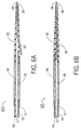
- FIGS. 6A and 6B illustrate a balloon angioplasty catheter 60 that can provide either over-the-wire or rapid exchange capability.
- this design has an inner shaft 51, outer shaft 52, radiopaque marker band 53, balloon 54, and a distal tip 65 which has a guide wire proximal exit port 62 and guide wire distal exit port 64.
- FIG. 6A when the guide wire 30 exits the distal tip 65 at the guide wire's proximal exit port 62, one achieves a rapid exchange mode.
- FIG. 6B when the guide wire 30 exits at the proximal end (not shown) of the balloon angioplasty catheter 60 that lies outside the patient's body, then an over-the-wire mode is achieved. Therefore, the balloon angioplasty catheter 60 can be used in either an over-the-wire or rapid exchange mode depending on which guide wire proximal exit port is used.
- the gradually tapered distal tips 30, 130, 55 and 65 of FIGS. 2A, 2B, 4, 6A, 6B and 7 have a common feature which is an important aspect of this invention, namely a gradually tapered shape which is a frustrum of a cone that has a continuous outer surface.
- Continuous outer surface is defined herein as one that does not have abrupt changes in slope as noted for the distal section of the prior art balloon angioplasty catheter I illustrated in FIG. 1. Such a continuous outer surface allows a decreased force to push it through a tight stenosis as compared to the distal section of a conventional, prior art balloon angioplasty catheter.
- the conventional prior art balloon angioplasty catheter has a distal portion that has a sloped angle greater than 10 degrees followed by a centrally located cylindrical portion which has a zero slope angle.
- a continuous outer surface may have a proximal or a distal portion that has a zero slope angle
- the distal tip's central portion is characterized by a non-zero slope that is always less than 3 degrees and optimally less than 1 degree.
- FIGS. 1, 2A, 2B, 4, 6A, 6B and 7 each exaggerates transverse dimensions as compared to longitudinal dimensions.
- the balloon angioplasty catheters 10, 110, 50 and 60 would optimally be much thinner and longer as to compared to what is shown in these figures.
Abstract
Description
- This invention is a balloon angioplasty catheter that is used for dilatation of stenotic arteries in human subjects.
- A very important attribute for a balloon angioplasty catheter is to penetrate through a tight arterial stenosis. By a tight stenosis is meant a narrowing in an artery where the minimal luminal diameter is less than approximately 0.7 mm. Such "tight stenoses" would include a total blockage of the artery.
- The well known attribute for a balloon angioplasty catheter to allow passage through such a tight stenosis is low profile; i.e., a small outside diameter at the distal section of the balloon angioplasty catheter. However, low profile has the disadvantage of disallowing balloons that are thick walled which are desirable for high pressure dilatation of a hard stenosis. Furthermore, any balloon angioplasty catheter that requires a guide wire to pass through an inner shaft as well as through the balloon of the balloon angioplasty catheter results in an increased profile at the distal section of the catheter.
- The invention is set out in the accompanying independent and dependent claims. According to one aspect of the invention, there is provided a balloon angioplasty catheter system for the dilation of an arterial stenosis in a human subject, the balloon angioplasty catheter system comprising:
- a balloon angioplasty catheter having a proximal end and a distal section;
- an uninflated balloon located at the distal section of the balloon angioplasty catheter; and
- an elongate, gradually tapered distal tip in the general form of a frustrum of a cone having a continuous outer surface with an average slope angle of less than 3 degrees with respect to a longitudinal axis of the distal tip, the frustrum of the cone having its smallest diameter at a distal end of the distal tip, a proximal end of the distal tip being proximate to the uninflated balloon the proximal end of distal tip being situated immediately adjacent to a blunt distal fold of the uninflated balloon, the tip also being directly and fixedly attached to the distal end of the uninflated balloon.
-
- Similar balloon angioplasty catheters are disclosed in document EP 0 186 267 and in prior european patent application EP 0 868 927 (document according to Article 54(3) EPC).
- An embodiment of the present invention is a balloon angioplasty catheter that combines a catheter shaft having increased pushability with an elongate, gradually tapered, distal tip that is specifically designed to penetrate through a tight stenosis. This is in contrast to prior art balloon angioplasty catheters which have a distal section that does not have a truly gradual taper. Therefore, they create more resistance to being pushed through a tight stenosis as compared to a structure that has a gradually tapered distal tip.
- The distal tip is preferably highly flexible and/or lubricity coated. The distal end of the tip is preferably formed as a very thin-walled, tapered, frustrum of a cone that is capable of following a guide wire through even the most tortuous coronary arteries. The proximal end of the tip has a diameter that is equal to or slightly larger than the diameter of an angioplasty balloon that is wrapped around a catheter shaft at a distal section of the balloon angioplasty catheter. One embodiment of the invention includes a thin-walled tube located at the proximal end of the distal tip which extends over the distal end of the angioplasty balloon. This design can prevent the distal end of the wrapped uninflated balloon from engaging the arterial wall as it is pushed through a tight stenosis.
- The balloon angioplasty catheter can have one or two elongated, coaxial cylindrical shafts that extend from the balloon angioplasty catheter's proximal end to the proximal end of the distal tip. By employing a woven metal wire elongated tubular structure onto which a plastic material is extruded, the shaft(s) of the balloon angioplasty catheter can provide increased pushability even though such a catheter employing metal wire would be somewhat less flexible as compared to a typical extruded plastic balloon angioplasty catheter shaft that does not include any metal wire. However, because of the comparatively long and extremely gradual taper of the balloon angioplasty catheter's distal tip, penetration of even a very tight stenosis becomes practical. In fact, an elongated, conically tapered, distal tip can provide stenotic dilatation (called "Dottering") of a tight stenosis when the shaft(s) of the balloon angioplasty catheter apply a distally directed force at the proximal end of the distal tip to push the distal tip through the tight stenosis. The larger diameter at the proximal end of the tip can dilate the stenosis sufficiently so that a multi-fold balloon located just proximal to the tip's proximal end can be easily passed through such a dilated stenosis. It should be noted that the outside diameter of the non-deployed balloon is equal to or slightly smaller than the diameter of the tip at the tip's proximal end.
- In one embodiment of this invention, the tip can have a central lumen throughout its length which would be the design for an "over-the-wire" type of balloon angioplasty catheter which is characterized by having the guide wire exit ports located at the proximal end and the distal end of the balloon angioplasty catheter. Another embodiment of this invention can have the guide wire distal exit port located at the distal end of the balloon angioplasty catheter, but the guide wire's proximal exit port would be placed at the side of the gradually tapered distal tip near the tip's proximal end and distal to the balloon. Such a balloon angioplasty catheter design is said to have a "rapid exchange" capability.
- Still another embodiment of the invention utilizes both a lumen placed through the distal tip and a second lumen that has the same distal exit port but has a guide wire proximal exit port located at the side of the distal tip near the tip's proximal end. Thus, this balloon angioplasty catheter would provide either over-the-wire or rapid exchange capability depending on how the guide wire was threaded through the distal tip.
- In an embodiment of the invention, the balloon angioplasty catheter's distal tip is an elongated frustrum of a cone having an extraordinarily gradual taper as opposed to prior art designs where the distal section of the balloon angioplasty catheter has several portions each of which is a short, steeply tapered portion or a short cylindrical portion having no taper what-so-ever. Any portion of a balloon angioplasty catheter's distal section that has a comparatively steep slope angle increases the distally directed push force required to push that balloon angioplasty catheter's distal section through a tight stenosis as compared to the force required to push through a gradually tapered distal tip that has an extraordinarily small slope angle throughout its entire length.
- Thus, an advantage of an embodiment of the invention is a balloon angioplasty catheter with increased distally directed pushability combined with an elongated, gradually tapered, distal tip with a continuous outer surface having a slope angle of less than 3 degrees, thus providing a system for penetration of a tight stenosis by Dottering.
- A balloon angioplasty catheter with a continuously tapered distal tip requires less push force to penetrate through a tight stenosis as compared to a distal section of a balloon angioplasty catheter that has a few portions that have a steep slope angle and others that are cylindrical portions that have a zero slope angle.
- Preferably the gradually tapered distal tip utilizes a central through lumen to provide an over-the-wire balloon angioplasty catheter design.
- Preferably, the gradually tapered distal tip has a guide wire proximal exit port at the side of the distal tip near the distal tip's proximal end and a guide wire distal exit port at the tip's distal end thus providing a rapid exchange capability for the balloon angioplasty catheter.
- Preferably the gradually tapered distal tip for the balloon angioplasty catheter has both a central lumen and a guide wire proximal exit port at the side of the distal tip near its proximal end thus providing either over-the-wire or rapid exchange capability for the balloon angioplasty catheter.
- In an embodiment of the invention the gradually tapered distal tip can provide pre-dilatation of a tight stenosis by Dottering prior to inflating the balloon of the balloon angioplasty catheter which balloon provides additional dilatation after the balloon is inflated.
- In one embodiment a single shaft is used for the balloon angioplasty catheter without a guide wire placed within that shaft, the interior passageway of the shaft being the inflation lumen for the balloon, the single shaft allowing a smaller outside diameter for the wrapped, uninflated balloon thus allowing a smaller diameter (i.e., lower profile) for the distal section of the balloon angioplasty catheter.
- These and other important objects and advantages of this invention will become apparent from the detailed description of the invention and the associated drawings provided herein.
- Exemplary embodiments of the invention are described hereinafter, by way of example only, with reference to the accompanying drawings, in which:
- FIG. 1 is a longitudinal cross section of a distal section of a conventional, prior art balloon angioplasty catheter.
- FIG. 2A is a longitudinal cross section of a distal section of a first embodiment of a balloon angioplasty catheter having a gradually tapered distal tip with a guide wire proximal exit port located near the proximal end of the distal tip for providing rapid exchange capability.
- FIG. 2B is a longitudinal cross section ofa distal section of a second embodiment of a balloon angioplasty catheter having a gradually tapered distal tip with a guide wire proximal exit port located near the proximal end of the distal tip for providing rapid exchange capability; the distal tip also having a thin-walled cylinder at its proximal end that extends over the distal end of the uninflated balloon.
- FIG. 3 is a transverse cross section of the rapid exchange balloon angioplasty catheter at section 3-3 of FIG. 2.
- FIG. 4 is longitudinal cross section of another embodiment of a distal section a balloon angioplasty catheter with a gradually tapered distal tip.
- FIG. 5 is a transverse cross section of the balloon angioplasty catheter at section 5-5 of FIG. 4.
- FIG. 6A is a longitudinal cross section of a distal section of a balloon angioplasty catheter that provides either over-the-wire or a rapid exchange capability with a guide wire shown for the balloon angioplasty catheter being used in its rapid exchange mode.
- FIG. 6B is a longitudinal cross section of a distal section of a balloon angioplasty catheter that provides either over-the-wire or a rapid exchange capability with a guide wire shown for the balloon angioplasty catheter being used in over-the-wire mode.
- FIG. 7 is a longitudinal cross section of the embodiment of FIGS. 4 and 5 shown at section 7-7 of FIG. 5.
-
- FIG. 1 illustrates the distal section of a conventional, prior art,
balloon angioplasty catheter 1 having aninner shaft 2, anouter shaft 3, an inflatable balloon 4,adhesive joints central lumen 7 and alongitudinal axis 8. Theinner shaft 2 has a somewhat steeply tapereddistal portion 2A that makes a slope angle "a" with thelongitudinal axis 8. This slope angle "a" is typically greater than 20 degrees and always greater than 5 degrees. Just proximal to thedistal portion 2A is acylindrical portion 2B that has a zero slope angle. - At the distal and proximal ends of the balloon 4, some balloon angioplasty catheters use a thin wedge of adhesive to join the balloon 4 at its distal end to the
inner shaft 2 and at the balloon's proximal end to the distal end of theouter shaft 3. Thus theadhesive wedge portions - The balloon 4 has a distal
cylindrical portion 4A that is fixed to theinner shaft 2 and a proximal cylindrical portion 4B that is joined to the distal end of theouter shaft 3. Bothcylindrical portions 4A and 4B have a zero slope angle. The balloon 4 has a comparatively bluntdistal fold 4C which can be difficult to push through a tight arterial stenosis. To ease the insertion of such a balloon 4 through a tight stenosis, manufacturers ofballoon angioplasty catheter 5 always strive for a "low profile" distal section of their balloon angioplasty catheter. "Low profile" really means as small an outside diameter as possible so that the bluntdistal fold 4C of the balloon 4 would not prevent passage of the distal section of the balloon angioplasty catheter through a tight stenosis. This requirement for the ultimate in low profile, typically dictates inflatable balloons with a very thin wall thus limiting the burst pressure of the balloon thus limiting the capability of the balloon to dilate a hard (calcified) stenosis. - The
balloon angioplasty catheters balloon angioplasty catheters balloon angioplasty catheter 10 that has either a steep slope angle or a wrapped balloon with a blunt distal fold that can catch on a tight stenosis, theballoon angioplasty catheters - The
balloon angioplasty catheters cylindrical shaft 12 with aballoon inflation lumen 16 through which inflation fluid can be used to inflate or deflate theballoon 20 by means of theside hole 15. A proximalradiopaque marker band 13P and a distal radiopaque marker band 13D are used to indicate by fluoroscopy that theballoon 20 is centered within an arterial stenosis. Theballoon angioplasty catheters distal tip longitudinal axis 8 of thedistal tip 30. By "gradually tapered" is meant an average slope angle "a" over the length of thedistal tip distal tip 30 typically lies between 1 and 5 cm. - The
balloon angioplasty catheter 110 shown in FIG. 2B has a thin-walledcylindrical section 120 that extends from the proximal end of thedistal tip 130 over the bluntdistal fold 20A of theballoon 20. This design guarantees that the bluntdistal fold 20A of theballoon 20 will not engage the wall of a tight stenosis which could prevent the passage of the distal section of theballoon angioplasty catheter 110 from penetrating such a tight stenosis. - Either the
distal tip balloon angioplasty catheter balloon angioplasty catheter distal tip balloon angioplasty catheter balloon 20 to a high pressure, typically greater than 15 atmospheres. Because thedistal tip balloon 20 can be increased thus allowing a thicker balloon wall thus providing the desired high balloon inflation pressure capability. - FIGS. 2A and 2B show that the
distal tip distal exit port 31 or 131 and a guide wireproximal exit port proximal exit port balloon angioplasty catheter - Since no guide wire is required to pass through the
central lumen 16 of theshaft 12, the outsider diameter of theshaft 12 can be smaller that the outside diameter of the inner shaft for any conventional balloon angioplasty catheter through which a guide wire is placed such as theballoon angioplasty catheter 1 shown in FIG. 1. This reduced outside diameter for theshaft 12 allows a smaller outside diameter for the wrappedballoon 20 as compared to a larger, outside diameter required for the prior art balloon 4 of theballoon angioplasty catheter 1 shown in FIG. 1. - Although the
shaft 12 can be made entirely from a plastic material, improved pushability for theballoon angioplasty catheter 10 can be obtained by making theshaft 12 from a thin-walled metal tube or an elongated woven wire cylinder over which a flexible plastic is extruded. Such tubular structures are well known in the art of extruding tubing for intravascular catheters. Furthermore, to improve pushability through a tight stenosis, the distal tip (as seen in FIGS. 2A, 2B, 4, 6A and 6B) should have a shape which is the frustum of a cone having its smallest diameter at the distal end of the distal tip. Preferably the tip should be conical in shape starting at the tip's distal end and extending for at least 50% of the tip's length. - FIGS. 4, 5 and 7 illustrate an alternative embodiment of the invention which is a
balloon angioplasty catheter 50 having aninner shaft 51, anouter shaft 52, aradiopaque marker band 53, aninflatable balloon 54 and adistal tip 55. Theannular passageway 59 is in fluid communication with theinterior chamber 49 of theballoon 54. Thus, thepassageway 59 is used for inflation and deflation of theballoon 54. Aguide wire 30 can be moved slideably through thecentral lumen 57 that extends through the entire length of theballoon angioplasty catheter 50 to achieve an over-the-wire mode. If theguide wire 30 has a guide wire proximal exit port that is within approximately 5 to 25 cm. proximal to theballoon 54, then a rapid exchange mode is achieved. - FIGS. 6A and 6B illustrate a
balloon angioplasty catheter 60 that can provide either over-the-wire or rapid exchange capability. Specifically, this design has aninner shaft 51,outer shaft 52,radiopaque marker band 53,balloon 54, and adistal tip 65 which has a guide wireproximal exit port 62 and guide wiredistal exit port 64. As seen in FIG. 6A, when theguide wire 30 exits thedistal tip 65 at the guide wire'sproximal exit port 62, one achieves a rapid exchange mode. As seen in FIG. 6B, when theguide wire 30 exits at the proximal end (not shown) of theballoon angioplasty catheter 60 that lies outside the patient's body, then an over-the-wire mode is achieved. Therefore, theballoon angioplasty catheter 60 can be used in either an over-the-wire or rapid exchange mode depending on which guide wire proximal exit port is used. - It should be noted that the gradually tapered
distal tips - It should be noted that, for the sake of clarity, FIGS. 1, 2A, 2B, 4, 6A, 6B and 7 each exaggerates transverse dimensions as compared to longitudinal dimensions. Thus the
balloon angioplasty catheters - Various other modifications, adaptations, and alternative designs are of course possible in light of the above teachings. Therefore, it should be understood at this time that the invention may be practiced otherwise than as specifically described herein.
Claims (13)
- A balloon angioplasty catheter system for the dilation of an arterial stenosis in a human subject, the balloon angioplasty catheter system comprising:a balloon angioplasty catheter (10, 110, 50, 60) having a proximal end and a distal section;an uninflated balloon (20) located at the distal section of the balloon angioplasty catheter; andan elongate, gradually tapered distal tip (30, 130, 55, 65) in the general form of a frustrum of a cone having a continuous outer surface with an average slope angle of less than 3 degrees with respect to a longitudinal axis (8) of the distal tip, the frustrum of the cone having its smallest diameter at a distal end of the distal tip, a proximal end of the distal tip being proximate to the uninflated balloon the proximal end of distal tip being situated immediately adjacent to a blunt distal fold (20A) of the uninflated balloon, the tip also being directly and fixedly attached to the distal end of the uninflated balloon.
- A balloon angioplasty catheter system according to Claim 1 comprising:a flexible guide wire;the distal tip having a guide wire lumen with the guide wire placed slidably therein, the guide wire lumen extending in a proximal direction from the tip's distal end, the distal tip also having a guide wire distal exit port (31, 131, 62) at the tip's distal end through which the guide wire exits from the balloon angioplasty catheter.
- A balloon angioplasty catheter system according to any preceding claim, wherein:the balloon angioplasty catheter has a single elongate hollow cylindrical shaft (12) which has a single unobstructed lumen (16), the shaft having a proximal end and a distal end, the shaft extending for most of the length of the balloon angioplasty catheter;the balloon angioplasty catheter proximal end is placed outside of the body of the human subject; andthe uninflated balloon is fixedly attached to the shaft at the balloon angioplasty catheter distal section, the balloon having a proximal end and a distal end and having a blunt distal fold located just proximal to the balloon's distal end.
- A balloon angioplasty catheter system according to Claim 1 wherein:the uninflated balloon has an interior chamber located at the distal section of the balloon angioplasty catheter, the balloon having a proximal end and a distal end and having at least two folds, each fold having an outer surface, the balloon also having an outside diameter that is measured across the outer surface of the folds of the uninflated balloon, the balloon also having a blunt distal fold located near the balloon's distal end, the balloon angioplasty catheter also having an elongate, hollow, generally cylindrical inner shaft (51) having a central lumen (57) through which the guide wire can move slidably and an elongate, hollow, generally cylindrical outer shaft (52) that is coaxially mounted around the inner shaft, the outer shaft having an interior lumen (59) that is in fluid communication with the interior chamber (49) of the balloon, the inner shaft and the outer shaft each having a distal end, the distal end of the inner shaft being fixedly attached to the distal end of the balloon, and the distal end of the outer shaft being fixedly attached to the proximal end of the balloon; andthe distal tip is located at the distal section of the balloon angioplasty catheter, with the proximal end of the distal tip being situated immediately adjacent to the blunt distal fold of the uninflated balloon, the distal tip being fixedly and directly attached to the distal end of the uninflated balloon, the distal tip having a guide wire lumen for receiving a guide wire and extending in a proximal direction from the distal tip's distal end, the distal tip having an outside diameter at its proximal end that is equal to or slightly larger than the outside diameter of the uninflated balloon.
- A balloon angioplasty catheter system according to any preceding claim, wherein the diameter of the distal tip at its promixal end is equal to or larger than the diameter of the uninflated balloon.
- A balloon angioplasty catheter system according to any preceding claim, wherein there are two radiopaque marker bands placed coaxially around the shaft of the balloon angioplasty catheter, the two radiopaque marker bands consisting of a proximal radiopaque marker band (13P) being located near the proximal end of the balloon and a distal radiopaque marker band (13D) being located near the distal end of the balloon.
- A balloon angioplasty catheter system according to any preceding claim, wherein the distal tip includes a thin-walled cylindrical section (120) that extends from the proximal end of the distal tip over a, or the, blunt distal fold of the uninflated balloon.
- A balloon angioplasty catheter system according to any preceding claim, wherein the distal tip includes a proximal exit port (32, 132, 62) placed distal to the balloon through which a, or the, guide wire can exit from the distal tip thus providing a rapid exchange capability for the balloon angioplasty catheter.
- A balloon angioplasty catheter system according to any preceding claim, wherein a, or the, lumen within the distal tip of the balloon angioplasty catheter extends centrally throughout the entire length of the distal tip.
- A balloon angioplasty catheter system according to any preceding claim, wherein the balloon angioplasty catheter has a proximal exit port located at the proximal end of the balloon angioplasty catheter that lies outside the body of the human subject thereby providing an over-the-wire capability for the balloon angioplasty catheter.
- A balloon angioplasty catheter according to any preceding claim, wherein the balloon angioplasty catheter has a proximal exit port that lies proximal to the proximal end of the balloon but within a distance of 25 cm from the proximal end of the balloon thereby providing a rapid exchange capability for the balloon angioplasty catheter.
- A balloon angioplasty catheter system according to any preceding claim, wherein the distal tip has a guide wire proximal exit port located distal to the balloon and the distal tip also has a central lumen throughout its entire length thereby providing either an over-the-wire or a rapid exchange capability for the balloon angioplasty catheter.
- A balloon angioplasty catheter system according to any preceding claim, wherein the average slope angle ("a") of the continuous outer surface is less than 1.0 degree.
Applications Claiming Priority (2)
| Application Number | Priority Date | Filing Date | Title |
|---|---|---|---|
| US840788 | 1997-04-16 | ||
| US08/840,788 US5830227A (en) | 1997-04-16 | 1997-04-16 | Balloon angioplasty catheter with enhanced capability to penetrate a tight arterial stenosis |
Publications (3)
| Publication Number | Publication Date |
|---|---|
| EP0875263A2 EP0875263A2 (en) | 1998-11-04 |
| EP0875263A3 EP0875263A3 (en) | 1999-01-07 |
| EP0875263B1 true EP0875263B1 (en) | 2004-02-11 |
Family
ID=25283239
Family Applications (1)
| Application Number | Title | Priority Date | Filing Date |
|---|---|---|---|
| EP98302924A Expired - Lifetime EP0875263B1 (en) | 1997-04-16 | 1998-04-15 | Balloon angioplasty catheter |
Country Status (7)
| Country | Link |
|---|---|
| US (1) | US5830227A (en) |
| EP (1) | EP0875263B1 (en) |
| JP (1) | JPH10305102A (en) |
| AT (1) | ATE259251T1 (en) |
| AU (1) | AU6079798A (en) |
| CA (1) | CA2234894C (en) |
| DE (1) | DE69821543T2 (en) |
Cited By (1)
| Publication number | Priority date | Publication date | Assignee | Title |
|---|---|---|---|---|
| US7654264B2 (en) | 2006-07-18 | 2010-02-02 | Nellcor Puritan Bennett Llc | Medical tube including an inflatable cuff having a notched collar |
Families Citing this family (41)
| Publication number | Priority date | Publication date | Assignee | Title |
|---|---|---|---|---|
| US6325825B1 (en) * | 1999-04-08 | 2001-12-04 | Cordis Corporation | Stent with variable wall thickness |
| US6270521B1 (en) * | 1999-05-21 | 2001-08-07 | Cordis Corporation | Stent delivery catheter system for primary stenting |
| US6206852B1 (en) | 1999-12-15 | 2001-03-27 | Advanced Cardiovascular Systems, Inc. | Balloon catheter having a small profile catheter |
| US6569180B1 (en) | 2000-06-02 | 2003-05-27 | Avantec Vascular Corporation | Catheter having exchangeable balloon |
| US20030055377A1 (en) * | 2000-06-02 | 2003-03-20 | Avantec Vascular Corporation | Exchangeable catheter |
| US7238168B2 (en) * | 2000-06-02 | 2007-07-03 | Avantec Vascular Corporation | Exchangeable catheter |
| US7077841B2 (en) * | 2001-03-26 | 2006-07-18 | Curon Medical, Inc. | Systems and methods employing a guidewire for positioning and stabilizing external instruments deployed within the body |
| US6960188B2 (en) * | 2001-11-30 | 2005-11-01 | Abbott Laboratories Vascular Entities Limited | Catheter having enhanced distal pushability |
| US7300415B2 (en) * | 2002-12-20 | 2007-11-27 | Advanced Cardiovascular Systems, Inc. | Balloon catheter having an external guidewire |
| KR100483834B1 (en) * | 2003-01-06 | 2005-04-20 | 삼성전자주식회사 | Rapid thermal processing apparatus including a revolution typed heating unit |
| JP2004249093A (en) * | 2003-01-31 | 2004-09-09 | Olympus Corp | Basket forceps |
| JP2011019937A (en) * | 2003-01-31 | 2011-02-03 | Olympus Corp | Basket forceps |
| JP2004275435A (en) * | 2003-03-14 | 2004-10-07 | Terumo Corp | Catheter |
| US7022104B2 (en) | 2003-12-08 | 2006-04-04 | Angioscore, Inc. | Facilitated balloon catheter exchange |
| US7780715B2 (en) * | 2004-03-04 | 2010-08-24 | Y Med, Inc. | Vessel treatment devices |
| US7753951B2 (en) * | 2004-03-04 | 2010-07-13 | Y Med, Inc. | Vessel treatment devices |
| US7766951B2 (en) * | 2004-03-04 | 2010-08-03 | Y Med, Inc. | Vessel treatment devices |
| US9050437B2 (en) * | 2004-03-04 | 2015-06-09 | YMED, Inc. | Positioning device for ostial lesions |
| US8152767B2 (en) * | 2005-05-27 | 2012-04-10 | Cook Medical Technologies Llc | Low profile introducer apparatus |
| US7901378B2 (en) * | 2006-05-11 | 2011-03-08 | Y-Med, Inc. | Systems and methods for treating a vessel using focused force |
| US8486025B2 (en) * | 2006-05-11 | 2013-07-16 | Ronald J. Solar | Systems and methods for treating a vessel using focused force |
| US20070276287A1 (en) * | 2006-05-12 | 2007-11-29 | General Electric Company | Catheter |
| US20080009720A1 (en) * | 2006-05-12 | 2008-01-10 | General Electric Company | Catheter connector |
| US20090099517A1 (en) * | 2007-10-10 | 2009-04-16 | C. R. Bard, Inc. | Reinforced, non-compliant angioplasty balloon |
| JP5326313B2 (en) * | 2008-03-21 | 2013-10-30 | ニプロ株式会社 | Thrombus capture catheter |
| US8715331B2 (en) | 2008-08-06 | 2014-05-06 | Boston Scientific Scimed, Inc. | Stent edge protection and methods |
| GB2471517B (en) * | 2009-07-02 | 2011-09-21 | Cook William Europ | Implant deployment catheter |
| US20120184987A1 (en) * | 2009-10-08 | 2012-07-19 | Cook Medical Technologies Llc | Vascular Implant Retrieval Method, Retrieval Assembly And Tool For Same |
| KR101396017B1 (en) | 2011-08-22 | 2014-05-27 | 연세대학교 산학협력단 | Balloon catheter |
| US8747428B2 (en) * | 2012-01-12 | 2014-06-10 | Fischell Innovations, Llc | Carotid sheath with entry and tracking rapid exchange dilators and method of use |
| US20140025143A1 (en) * | 2012-07-17 | 2014-01-23 | Prospex Medical III | Devices and methods to reduce myocardial reperfusion injury |
| AU2014311441A1 (en) | 2013-08-26 | 2016-03-10 | Merit Medical Systems, Inc. | Sheathless guide, rapid exchange dilator and associated methods |
| JP6442229B2 (en) * | 2014-10-30 | 2018-12-19 | 株式会社グッドマン | Balloon catheter |
| US10357631B2 (en) | 2015-05-29 | 2019-07-23 | Covidien Lp | Catheter with tapering outer diameter |
| US11219740B2 (en) | 2015-05-29 | 2022-01-11 | Covidien Lp | Catheter including tapering coil member |
| US11738180B2 (en) * | 2016-08-23 | 2023-08-29 | Shuttle Catheters Pc | Endovascular remotely steerable guidewire catheter |
| CN106178192A (en) * | 2016-08-31 | 2016-12-07 | 杨媛媛 | Locking artery/vein indwelling needle |
| US10926060B2 (en) | 2017-03-02 | 2021-02-23 | Covidien Lp | Flexible tip catheter |
| US11131504B2 (en) * | 2017-03-08 | 2021-09-28 | Boe Technology Group Co., Ltd. | Temperature monitoring system and method for a substrate heating furnace |
| US10537710B2 (en) | 2017-04-20 | 2020-01-21 | Covidien Lp | Catheter including an inner liner with a flexible distal section |
| CN108283758B (en) * | 2018-01-24 | 2021-07-23 | 张海军 | Drug eluting balloon catheter with thrombus breaking and dissolving and suction functions |
Family Cites Families (8)
| Publication number | Priority date | Publication date | Assignee | Title |
|---|---|---|---|---|
| US4637396A (en) * | 1984-10-26 | 1987-01-20 | Cook, Incorporated | Balloon catheter |
| US5192296A (en) * | 1988-08-31 | 1993-03-09 | Meadox Medicals, Inc. | Dilatation catheter |
| US5395332A (en) * | 1990-08-28 | 1995-03-07 | Scimed Life Systems, Inc. | Intravascualr catheter with distal tip guide wire lumen |
| EP0517654B1 (en) * | 1991-06-03 | 1996-07-17 | Schneider (Europe) Ag | Catheter system to mechanically dilate the coronary stenosis |
| US5154725A (en) * | 1991-06-07 | 1992-10-13 | Advanced Cardiovascular Systems, Inc. | Easily exchangeable catheter system |
| US5328472A (en) * | 1992-07-27 | 1994-07-12 | Medtronic, Inc. | Catheter with flexible side port entry |
| US5423755A (en) * | 1992-08-26 | 1995-06-13 | Advanced Cardiovascular Systems, Inc. | Catheter for prostatic urethral dilatation |
| US5653689A (en) * | 1995-09-30 | 1997-08-05 | Abacus Design & Development, Inc. | Infusion catheter |
-
1997
- 1997-04-16 US US08/840,788 patent/US5830227A/en not_active Expired - Lifetime
-
1998
- 1998-04-14 AU AU60797/98A patent/AU6079798A/en not_active Abandoned
- 1998-04-14 CA CA002234894A patent/CA2234894C/en not_active Expired - Lifetime
- 1998-04-15 EP EP98302924A patent/EP0875263B1/en not_active Expired - Lifetime
- 1998-04-15 JP JP10119961A patent/JPH10305102A/en active Pending
- 1998-04-15 DE DE69821543T patent/DE69821543T2/en not_active Expired - Lifetime
- 1998-04-15 AT AT98302924T patent/ATE259251T1/en active
Cited By (2)
| Publication number | Priority date | Publication date | Assignee | Title |
|---|---|---|---|---|
| US7654264B2 (en) | 2006-07-18 | 2010-02-02 | Nellcor Puritan Bennett Llc | Medical tube including an inflatable cuff having a notched collar |
| US8096299B2 (en) | 2006-07-18 | 2012-01-17 | Nellcor Puritan Bennett Llc | Medical tube including an inflatable cuff having a notched collar |
Also Published As
| Publication number | Publication date |
|---|---|
| EP0875263A2 (en) | 1998-11-04 |
| AU6079798A (en) | 1998-10-22 |
| CA2234894C (en) | 2006-11-21 |
| JPH10305102A (en) | 1998-11-17 |
| ATE259251T1 (en) | 2004-02-15 |
| EP0875263A3 (en) | 1999-01-07 |
| CA2234894A1 (en) | 1998-10-16 |
| DE69821543T2 (en) | 2004-07-01 |
| US5830227A (en) | 1998-11-03 |
| DE69821543D1 (en) | 2004-03-18 |
Similar Documents
| Publication | Publication Date | Title |
|---|---|---|
| EP0875263B1 (en) | Balloon angioplasty catheter | |
| US6190393B1 (en) | Direct stent delivery catheter system | |
| US6379365B1 (en) | Stent delivery catheter system having grooved shaft | |
| US5542925A (en) | Dilatation catheter with oblong perfusion ports | |
| US5100381A (en) | Angioplasty catheter | |
| US5846246A (en) | Dual-balloon rapid-exchange stent delivery catheter with guidewire channel | |
| US7300415B2 (en) | Balloon catheter having an external guidewire | |
| CA2321040C (en) | Dilatation and stent delivery system for bifurcation lesions | |
| CA1315632C (en) | Kissing balloon catheter | |
| US5338298A (en) | Double-tapered balloon | |
| US5807355A (en) | Catheter with rapid exchange and OTW operative modes | |
| US6458099B2 (en) | Catheters having rapid-exchange and over-the-wire operating modes | |
| US5360401A (en) | Catheter for stent delivery | |
| US6270521B1 (en) | Stent delivery catheter system for primary stenting | |
| US5607394A (en) | Dilatation catheter having a field stylet | |
| CA2232900C (en) | Stent delivery catheter system | |
| US6514228B1 (en) | Balloon catheter having high flow tip | |
| US6991639B2 (en) | Catheter with removable balloon protector and stent delivery system with removable stent protector | |
| WO1994021321A1 (en) | Hybrid balloon angioplasty catheter and methods of use | |
| CA2238109A1 (en) | Stent deployment device with two balloons | |
| EP1493403B1 (en) | Balloon catheter with self-centering tip | |
| EP1518582B1 (en) | Rapid-exchange balloon catheter with hypotube shaft | |
| US20060282110A1 (en) | Advanceable, non-removable guide wire balloon catheter delivery system for a stent and method | |
| EP3212273B1 (en) | Elastic tip for an adjustable length angioplasty balloon sheath | |
| US20060253185A1 (en) | Catheter for stent delivery having expanded inner member |
Legal Events
| Date | Code | Title | Description |
|---|---|---|---|
| PUAI | Public reference made under article 153(3) epc to a published international application that has entered the european phase |
Free format text: ORIGINAL CODE: 0009012 |
|
| AK | Designated contracting states |
Kind code of ref document: A2 Designated state(s): AT BE CH CY DE DK ES FI FR GB GR IE IT LI LU MC NL PT SE |
|
| AX | Request for extension of the european patent |
Free format text: AL;LT;LV;MK;RO;SI |
|
| PUAL | Search report despatched |
Free format text: ORIGINAL CODE: 0009013 |
|
| AK | Designated contracting states |
Kind code of ref document: A3 Designated state(s): AT BE CH CY DE DK ES FI FR GB GR IE IT LI LU MC NL PT SE |
|
| AX | Request for extension of the european patent |
Free format text: AL;LT;LV;MK;RO;SI |
|
| 17P | Request for examination filed |
Effective date: 19990623 |
|
| AKX | Designation fees paid |
Free format text: AT BE CH CY DE DK ES FI FR GB GR IE IT LI LU MC NL PT SE |
|
| AXX | Extension fees paid |
Free format text: AL PAYMENT 19990623;LT PAYMENT 19990623;LV PAYMENT 19990623;MK PAYMENT 19990623;RO PAYMENT 19990623;SI PAYMENT 19990623 |
|
| 17Q | First examination report despatched |
Effective date: 20020506 |
|
| RAP1 | Party data changed (applicant data changed or rights of an application transferred) |
Owner name: CORDIS CORPORATION |
|
| RIN1 | Information on inventor provided before grant (corrected) |
Inventor name: FISCHELL, TIM A. Inventor name: FISCHELL, DAVID R. Inventor name: FISCHELL, ROBERT E. |
|
| GRAP | Despatch of communication of intention to grant a patent |
Free format text: ORIGINAL CODE: EPIDOSNIGR1 |
|
| GRAS | Grant fee paid |
Free format text: ORIGINAL CODE: EPIDOSNIGR3 |
|
| GRAA | (expected) grant |
Free format text: ORIGINAL CODE: 0009210 |
|
| AK | Designated contracting states |
Kind code of ref document: B1 Designated state(s): AT BE CH CY DE DK ES FI FR GB GR IE IT LI LU MC NL PT SE |
|
| AX | Request for extension of the european patent |
Extension state: AL LT LV MK RO SI |
|
| PG25 | Lapsed in a contracting state [announced via postgrant information from national office to epo] |
Ref country code: FI Free format text: LAPSE BECAUSE OF FAILURE TO SUBMIT A TRANSLATION OF THE DESCRIPTION OR TO PAY THE FEE WITHIN THE PRESCRIBED TIME-LIMIT Effective date: 20040211 Ref country code: CY Free format text: LAPSE BECAUSE OF FAILURE TO SUBMIT A TRANSLATION OF THE DESCRIPTION OR TO PAY THE FEE WITHIN THE PRESCRIBED TIME-LIMIT Effective date: 20040211 |
|
| REG | Reference to a national code |
Ref country code: GB Ref legal event code: FG4D |
|
| REG | Reference to a national code |
Ref country code: CH Ref legal event code: NV Representative=s name: MICHELI & CIE INGENIEURS-CONSEILS Ref country code: CH Ref legal event code: EP |
|
| REG | Reference to a national code |
Ref country code: IE Ref legal event code: FG4D |
|
| REF | Corresponds to: |
Ref document number: 69821543 Country of ref document: DE Date of ref document: 20040318 Kind code of ref document: P |
|
| PG25 | Lapsed in a contracting state [announced via postgrant information from national office to epo] |
Ref country code: LU Free format text: LAPSE BECAUSE OF NON-PAYMENT OF DUE FEES Effective date: 20040415 |
|
| PG25 | Lapsed in a contracting state [announced via postgrant information from national office to epo] |
Ref country code: MC Free format text: LAPSE BECAUSE OF NON-PAYMENT OF DUE FEES Effective date: 20040430 |
|
| PG25 | Lapsed in a contracting state [announced via postgrant information from national office to epo] |
Ref country code: GR Free format text: LAPSE BECAUSE OF FAILURE TO SUBMIT A TRANSLATION OF THE DESCRIPTION OR TO PAY THE FEE WITHIN THE PRESCRIBED TIME-LIMIT Effective date: 20040511 Ref country code: DK Free format text: LAPSE BECAUSE OF FAILURE TO SUBMIT A TRANSLATION OF THE DESCRIPTION OR TO PAY THE FEE WITHIN THE PRESCRIBED TIME-LIMIT Effective date: 20040511 |
|
| PG25 | Lapsed in a contracting state [announced via postgrant information from national office to epo] |
Ref country code: ES Free format text: LAPSE BECAUSE OF FAILURE TO SUBMIT A TRANSLATION OF THE DESCRIPTION OR TO PAY THE FEE WITHIN THE PRESCRIBED TIME-LIMIT Effective date: 20040522 |
|
| REG | Reference to a national code |
Ref country code: SE Ref legal event code: TRGR |
|
| LTIE | Lt: invalidation of european patent or patent extension |
Effective date: 20040211 |
|
| ET | Fr: translation filed | ||
| PLBE | No opposition filed within time limit |
Free format text: ORIGINAL CODE: 0009261 |
|
| STAA | Information on the status of an ep patent application or granted ep patent |
Free format text: STATUS: NO OPPOSITION FILED WITHIN TIME LIMIT |
|
| 26N | No opposition filed |
Effective date: 20041112 |
|
| PG25 | Lapsed in a contracting state [announced via postgrant information from national office to epo] |
Ref country code: PT Free format text: LAPSE BECAUSE OF NON-PAYMENT OF DUE FEES Effective date: 20040711 |
|
| REG | Reference to a national code |
Ref country code: FR Ref legal event code: PLFP Year of fee payment: 19 |
|
| REG | Reference to a national code |
Ref country code: FR Ref legal event code: PLFP Year of fee payment: 20 |
|
| PGFP | Annual fee paid to national office [announced via postgrant information from national office to epo] |
Ref country code: NL Payment date: 20170426 Year of fee payment: 20 |
|
| PGFP | Annual fee paid to national office [announced via postgrant information from national office to epo] |
Ref country code: GB Payment date: 20170427 Year of fee payment: 20 Ref country code: CH Payment date: 20170427 Year of fee payment: 20 Ref country code: FR Payment date: 20170426 Year of fee payment: 20 Ref country code: DE Payment date: 20170427 Year of fee payment: 20 Ref country code: IE Payment date: 20170428 Year of fee payment: 20 |
|
| PGFP | Annual fee paid to national office [announced via postgrant information from national office to epo] |
Ref country code: IT Payment date: 20170421 Year of fee payment: 20 Ref country code: SE Payment date: 20170427 Year of fee payment: 20 Ref country code: AT Payment date: 20170321 Year of fee payment: 20 Ref country code: BE Payment date: 20170427 Year of fee payment: 20 |
|
| REG | Reference to a national code |
Ref country code: DE Ref legal event code: R071 Ref document number: 69821543 Country of ref document: DE |
|
| REG | Reference to a national code |
Ref country code: NL Ref legal event code: MK Effective date: 20180414 |
|
| REG | Reference to a national code |
Ref country code: CH Ref legal event code: PL |
|
| REG | Reference to a national code |
Ref country code: GB Ref legal event code: PE20 Expiry date: 20180414 |
|
| REG | Reference to a national code |
Ref country code: SE Ref legal event code: EUG |
|
| REG | Reference to a national code |
Ref country code: IE Ref legal event code: MK9A |
|
| REG | Reference to a national code |
Ref country code: AT Ref legal event code: MK07 Ref document number: 259251 Country of ref document: AT Kind code of ref document: T Effective date: 20180415 Ref country code: BE Ref legal event code: MK Effective date: 20180415 |
|
| PG25 | Lapsed in a contracting state [announced via postgrant information from national office to epo] |
Ref country code: IE Free format text: LAPSE BECAUSE OF EXPIRATION OF PROTECTION Effective date: 20180415 Ref country code: GB Free format text: LAPSE BECAUSE OF EXPIRATION OF PROTECTION Effective date: 20180414 |