EP0872597B1 - Earth structures - Google Patents
Earth structures Download PDFInfo
- Publication number
- EP0872597B1 EP0872597B1 EP98112939A EP98112939A EP0872597B1 EP 0872597 B1 EP0872597 B1 EP 0872597B1 EP 98112939 A EP98112939 A EP 98112939A EP 98112939 A EP98112939 A EP 98112939A EP 0872597 B1 EP0872597 B1 EP 0872597B1
- Authority
- EP
- European Patent Office
- Prior art keywords
- earth
- facing
- stabilising
- connectors
- region
- Prior art date
- Legal status (The legal status is an assumption and is not a legal conclusion. Google has not performed a legal analysis and makes no representation as to the accuracy of the status listed.)
- Expired - Lifetime
Links
Images


Classifications
-
- E—FIXED CONSTRUCTIONS
- E02—HYDRAULIC ENGINEERING; FOUNDATIONS; SOIL SHIFTING
- E02D—FOUNDATIONS; EXCAVATIONS; EMBANKMENTS; UNDERGROUND OR UNDERWATER STRUCTURES
- E02D29/00—Independent underground or underwater structures; Retaining walls
- E02D29/02—Retaining or protecting walls
- E02D29/0225—Retaining or protecting walls comprising retention means in the backfill
- E02D29/0241—Retaining or protecting walls comprising retention means in the backfill the retention means being reinforced earth elements
-
- E—FIXED CONSTRUCTIONS
- E02—HYDRAULIC ENGINEERING; FOUNDATIONS; SOIL SHIFTING
- E02D—FOUNDATIONS; EXCAVATIONS; EMBANKMENTS; UNDERGROUND OR UNDERWATER STRUCTURES
- E02D29/00—Independent underground or underwater structures; Retaining walls
- E02D29/02—Retaining or protecting walls
- E02D29/0225—Retaining or protecting walls comprising retention means in the backfill
-
- E—FIXED CONSTRUCTIONS
- E02—HYDRAULIC ENGINEERING; FOUNDATIONS; SOIL SHIFTING
- E02D—FOUNDATIONS; EXCAVATIONS; EMBANKMENTS; UNDERGROUND OR UNDERWATER STRUCTURES
- E02D2200/00—Geometrical or physical properties
- E02D2200/13—Geometrical or physical properties having at least a mesh portion
Definitions
- the invention relates to earth structures, certain components for use in earth structures and to methods of constructing earth structures.
- the earth is stabilised throughout the mass by frictional engagement with the strips, thereby enabling the earth mass to behave as an elastic material with greatly improved resistance to failure.
- the facing of the known structure consists of a series of rows of "C" shaped mesh facing panels arranged one above another. The panels in each row are supported by laterally spaced support straps. These are also "C" shaped, each having an upright front portion in front of the panels and relatively short upper and lower rearwardly extending portions. These upper and lower portions are connected to an earth stabilising strip.
- each stabilising strip is located between a rearwardly extending upper portion at the top of a support strap in one row and a rearwardly extending lower portion at the bottom of a support strap in the row above.
- a bolt passes through the upper and lower rearwardly extending portions and the stabilising strip to form a secure connection.
- facing panels formed of mesh are lightweight and thus inexpensive compared to eg. concrete panels and that they allow the growth of vegetation on the facing, thus giving it a "green" appearance.
- the mesh facing panels are flexible and thus subject to deformation.
- the facing panels there is a tendency for the facing panels to bulge out where they span between the laterally spaced support straps. If it were desired, for aesthetic or other reasons, not to use the support straps and to connect the stabilising strips directly to the mesh facing panels, there would be an increased tendency for the panels to deform.
- the earth mass behind the facing may be structural backfill selected in a known manner to co-operate with the stabilising elements to produce a stable structure.
- the entire earth mass behind the facing may consist of such structural backfill.
- a stabilised earth structure comprising a plurality of elongate stabilising elements in an earth mass behind a facing, the earth mass comprising a first region of earth of a first type adjacent to the facing, and a second region of earth of a second type behind the first region.
- the present invention is characterised in that the first region of earth comprises soil suitable for plant growth and in that the earth structure further comprises a plurality of connectors behind the facing and connecting it to the stabilising elements, the connectors being located in said first region of earth and the stabilising elements being located in said second region of earth, whereby exposure of the stabilising elements to the first type of earth in the first region is substantially avoided.
- the first earth type is a type of soil, such as top soil, suitable for establishing plant growth to produce a "green" facing.
- the second earth type may be structural backfill. Earth of a type suitable for plant growth will generally contain organic matter and possibly fertilizers and will tend to have a high moisture content. This produces good conditions for plant growth but aggressive conditions for the earth stabilizing elements. However, by using connectors which are located in the first region of earth, the stabilising elements, which are located in the second region of earth, are not exposed to the aggressive conditions. It is thus possible to use conventional stabilising elements.
- the connectors can be designed with dimensions, the material they are made from and/or protective measures which take account of the aggressive conditions.
- the connector may have a thickness which is greater than that which is structurally needed.
- a 14mm bar may be used. This is an over thickness of 4mm, as compared to a 1mm over thickness which is typically used for a metal stabilising strip for a 70 year service life.
- Possible protective measures for the connector are galvanising or other metallic coating, e.g. zinc-aluminium alloy, applied by spraying or dipping.
- Plastic coatings, such as polyamide, polyurethane or epoxy, may also be used.
- the facing is preferably a mesh facing
- a facing with openings through which plants can grow for example being made up of concrete elements.
- the first and second regions of earth are separated by geosynthetic material, such as a sheet or sheets of geotextile.
- geosynthetic material such as a sheet or sheets of geotextile. This helps to ensure that the stabilising elements are not exposed to the first earth region and also, by providing a clear boundary between the two earth regions, helps to ensure that the first region is of the correct thickness.
- the geotextile is preferably a non-woven product with good filtration and drainage properties.
- first and second earth regions are useful if the connectors are attached to the facing at only one front attachment point, as well as when there are at least two front attachment portions.
- a preferred embodiment comprises an earth structure comprising a plurality of elongate stabilising elements in an earth mass behind a mesh facing, and a plurality of connectors behind the facing and connecting it to the stabilising elements, each connector having a rear attachment portion attached to a respective earth stabilising element, and having at least two spaced apart front attachment portions attached to the mesh facing.
- the forward earth pressure on the mesh facing is withstood by the stabilising elements connected to the facing via the connectors.
- the load on the mesh facing applied by the connector is distributed between those attachment portions, thereby reducing the deflection of the facing.
- the connector arrangement may be useful with other types of facing where it is desired to limit the deflections by distributing the load thereon.
- a preferred embodiment comprises an earth structure comprising a plurality of elongate stabilising elements in an earth mass behind a facing, and a plurality of connectors behind the facing and connecting it to the stabilising elements, each connector having a rear attachment portion attached to a respective earth stabilising element, and having at least two spaced apart front attachment portions attached to the facing.
- the facing may be made of a sheet or sheets of eg. metal.
- a preferred connector for connecting an earth stabilising element and a facing, comprises a rear attachment portion for attachment to an earth stabilising element, and at least two spaced apart front attachment portions for attachment to a facing.
- the front attachment portions may take any convenient form but are preferably arranged to hook on to a bar or lug of the facing. Thus each front attachment portion may be in the form of a hook.
- the connector has two front attachment portions and is substantially "V" shaped. The front attachment portions are preferably spaced apart in a horizontal or lateral direction.
- the connector may be formed by bending a bar, for example a 14mm diameter steel bar.
- the connectors are preferably capable of pivoting about a horizontal axis at the facing. This can advantageously permit the connectors to be at an appropriate orientation, normally horizontal, for any angle of facing.
- the slope of the facing can vary between 45° to the horizontal and vertical (90° to the horizontal). Pivotability of the connectors can advantageously be achieved by the hooks described above, which can pass round at least one substantially horizontal bar of the facing.
- the connectors extend rearwardly into the earth so as to have a length in this direction which is substantially less than the length of the stabilising elements, for example less than one quarter, preferably less than one fifth.
- a mesh facing comprises mesh panels arranged one above another, and the connectors connect a substantially horizontal bar of a lower facing panel with a substantially horizontal bar of an upper facing panel arranged above the lower facing panel.
- the connectors serve to connect lower and upper facing panels together as well as to connect the facing to the stabilising elements.
- the facing may be made up of mesh facing panels which are substantially "L" shaped in vertical cross-section. Typically, the front portion of the "L" will be substantially longer than the rearwardly extending portion, for example at least five times longer and preferably ten times longer.
- the "L” shaped panels can be used to form vertical facings and also non-vertical facings, even if the angle between the front portion and rearwardly extending portion of the "L” is 90°, if the connectors are pivotably attached and thus do not have to be at the same orientation as the rearwardly extending portion of the "L".
- This advantageously permits standardisation of the facing panels for facings of different slopes.
- a particular facing can have portions of different slopes whilst still using the same panels.
- the connectors are preferably arranged to permit relative vertical movement between the lower and upper facing panels. This can be achieved by the hooks described above, having a vertical play which is greater than the combined thickness of the two horizontal bars.
- the horizontal bar of an upper facing panel may be spaced upwardly from the horizontal bar of a lower facing panel by a wedge. This determines the position of the connector and thus the position of the stabilising element in the earth behind the facing. Once the upper facing panel has been backfilled the wedge can be removed and as settlement of the backfill takes place the upper facing panel can move downwardly by the thickness of the wedge before its horizontal bar engages the horizontal bar of the lower facing panel.
- the lower facing panel is therefore not pushed downwardly by the upper facing panel and thus any tendency for it to bulge forwardly is significantly reduced.
- at least two facing panels above each wedge will normally be backfilled before the wedge is removed.
- the use of "L" shaped facing panels, in preference to “C” shaped panels, advantageously permits relative vertical movement between lower and upper panels.
- the stabilising elements may take various forms and may for example be in the form of elongate ties connected at their rear ends to dead men anchors in the earth. Such a system operates by retaining a mass of earth between the facing and the dead men anchors.
- the stabilising elements are in the form of strips which stabilise the earth by frictional interaction therewith. It is preferred for the rear attachment portions of the connectors to extend laterally.
- the stabilising strips may for example be attached to the connectors by ties which loop round the laterally extending rear attachment portions. This arrangement is useful if the strips are metal strips, since the forward end of the strips can be secured to the ties by a vertical bolt.
- the stabilising strips may be attached to the connectors by looping round the laterally extending rear attachment portions, whereby each strip has first and second portions which extend rearwardly from its respective connector.
- the strips are geosynthetic strips which are generally quite flexible and capable of forming a loop.
- a tube of larger diameter may be provided round the laterally extending rear attachment portion of the connectors.
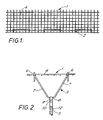
- a mesh facing panel 1 is provided with three connectors 2 each connected to an earth stabilising element in the form of a galvanised steel strip 3.
- the facing panel 1 has a vertical facing portion 4 and a relatively short rearwardly extending portion 5 at its lower end, so as to be substantially "L" shaped, the portions 4 and 5 being perpendicular to each other.
- Each connector 2 has two front attachment portions for attachment to the facing panel 1, each in the form of a hook 6, so that the connector consists of a double-hook arrangement. Extending rearwardly from the double-hook are a pair of converging portions 7 which are joined at the rear of the connector by a laterally extending rear attachment portion 8.
- a hair pin shaped lug 9 passes round the laterally extending portion 8 and is connected to the front end of the stabilising strip 3 by a vertical bolt 10.
- the strip has an integrally thickened portion 11, as described in British Patent Application No. 2177140, and a series of ribs 12 for improving frictional interaction with the surrounding earth, as described in British Patent No. 1563317.
- each hook 6 passes round a lower horizontal bar 13 of an upper facing panel and round an upper horizonal bar 14 of a lower facing panel.
- a temporary wood wedge 15 is placed at the attachment point between the bars 13 and 14.
- the wedge is removed, so that as the backfill settles and moves the stabilising strip 3 together with the connector 2 downwardly, the upper panel is able to move downwardly from the position shown in Figure 3 to that shown in Figure 4.
- the upper panel can move downwardly by the thickness of the wedge, which may be 4% of the height of the panel, before it starts to push downwardly on the lower panel, thereby reducing the tendency for the lower panel to bulge forwardly.
- the double hook arrangement helps to reduce forward deflection of the panels as they span horizontally between the connector attachment points, the arrangement also permits relative vertical movement between vertically adjacent panels and this tends to reduce forward deflection of the panels as they span vertically between vertically adjacent connectors.
- the facing panel 1 shown in Figures 1-4 is formed of electro-welded steel mesh with a nominal height of 0.625m and a width of 3m.
- the mesh bars are spaced both vertically and horizontally by 100mm.
- the vertical bars have a diameter of 10mm and the horizontal bars have a diameter of 8mm apart from the top bar and the last two bottom bars (one in the facing portion 4 and the other in the rearwardly extending portion 5) which have a diameter of 14mm for added stiffness.
- the use of a lighter facing panel is possible, being more cost effective and appropriate for low height and/or temporary structures.
- the facing panels have the same geometry but the diameters of all the bars are reduced by for example 2mm.
- the connectors shown in Figures 1-4 are bent from a 14mm galvanised steel bar.
- the inner vertical dimension of the hooks 6 is about 60mm.
- the length of the connector, in the direction extending rearwardly into the earth, is about 0.4m.
- the centre-to-centre spacing of the connectors is about 1m and their width, which is the spacing between the hooks 6, is about 0.55m.
- the deflection of the facing panels 1 in the horizontal plane of the connectors and at their centres may typically be 4-6mm.
- the maximum deflections between the connectors are less. At the edges of the panels the deflection may be about 10mm. These values are acceptable.
- Figures 5 and 6 show a second type of mesh facing panel 2 for use in a sloping, non-vertical facing (60° to the horizontal).
- the main difference from the first type of facing panel arrangement is that only two connectors 2 are used, each having a width of about 0.85m and being located at a centre-to-centre spacing of about 1.7m for a 3m wide panel.
- the panel is of greater height, having a nominal vertical height of 0.715m.
- the deflection of the facing panels in the horizontal plane of the connectors and at their centres may typically be about 6mm, with a maximum deflection of about 3mm between the connectors. At the edges of the panels the deflections may be negative (rearward), e.g. about 4mm.
- the rearwardly extending portions 5 of the facing panels of Figures 5 and 6 are perpendicular to the facing portions 4, as in the case of the vertical facing. This is possible because the connection between each connector 2 and two vertically adjacent panels permits pivoting of the upper facing panel to the desired angle.
- facing panels having a right angle between their facing portion 4 and rearwardly extending portion 5 can be used to form facings of various slopes, even permitting a change in the slope in the same structure. This is advantageous in that it enables standardisation of the facing panels.
- the earth structure shown in Figure 7 has a first region 20 of soil suitable for plant growth, and a second region 21 of structural backfill. The two regions are separated by geotextile sheets 22.
- the earth in the first region 20 may be a fine soil such as a silty sand that provides a certain water retention capacity. It can be top soil if the humus content is low and if compacting can be sufficiently achieved.
- the earth in the second region 21 will tend to be a coarser material with good drainage properties and less aggressive to the stabilising elements.
- a jute backing or "Enkamat" (trade mark) or the like is normally placed immediately behind the mesh facing panels to retain fine soil particles until vegetation is established.
- Posts 23 are driven into the foundation to provide alignment of a first course 31 of facing panels 1.
- a facing panel of the first course 31 with connectors 2 and stabilising strips 3 is placed and a first geotextile sheet 22 is laid on the soil behind the facing panel.
- a first layer A of structural backfill is placed on the stabilising strips 3.
- the geotextile sheet 22 is laid back along layer A and a layer B of top soil is placed between the panel 1 and the geotextile sheet 22.
- the geotextile sheet 22 is hung on the facing panel 1, as seen in Figure 8, and a second layer C of structural backfill is placed on the first layer A.
- the geotextile sheet 22 is removed from the facing panel 1 and passed back over layer C.
- a facing panel 1 of a second course 32 is placed on the facing panel of the first course, along with its connectors 2 and stabilising strips 3.
- the facing panel 1 is positioned vertically with a wedge 15 between lower horizontal bar 13 and upper horizontal bar 14 of the panel below. It is held in place by a temporary stay 24.
- the stabilising strips 3 are adjusted as shown by arrow D in Figure 9 to obtain the correct positioning of the facing panel.
- a second geotextile sheet 22 is laid on the strips 3 and a small volume E of backfill is placed on the strips to fix them in position.
- the geotextile sheet is folded back to leave a gap behind the facing panels 1 which are then backfilled with top soil layer F.
- the top soil in layers B and F is carefully compacted.
- the geotextile sheet 22 in the second course is hung on the facing panel of the second course, as shown in Figure 9, and a backfill layer G is placed on the second course of stabilising strips 3, in a similar manner to the placement of layer A described above.
- the stay 24 is removed and the panel 1 of the second course 32 is tilted back to the correct orientation and backfilled with top soil layer H, equivalent to layer B described above.
- the process is continued with further courses of facing panels.
- the last course, which in this case is the third course 33 the connectors 2 are hooked to a horizontal bar below the top of the panel 1, so that it can be buried and the tops of the upright bars of the panel can be bent rearwardly and downwardly for safety.
- the wood wedges 15 are then removed to enable the facing panels to move downwardly as the backfill settles, without significant bulging.
- FIGS 10 and 11 show an embodiment in which geosynthetic strips 40 are used to stabilise the earth.
- the arrangement is generally similar to the previously described embodiments, except that a tube 41 is placed on a bar before it is bent to the correct shape to form the connector 2.
- the stabilising strip 40 loops round the tube 41 so as to have upper and lower portions which diverge as they extend rearwardly into the earth behind the facing.
Abstract
Description
Claims (8)
- A stabilised earth structure comprising a plurality of elongate stabilising elements (3;40) in an earth mass behind a facing (4), the earth mass comprising a first region of earth of a first type (20) adjacent to the facing, and a second region of earth of a second type (21) behind the first region, characterised in that the first region of earth comprises soil suitable for plant growth and in that the earth structure further comprises a plurality of connectors (2) behind the facing and connecting it to the stabilising elements, the connectors being located in said first region of earth and the stabilising elements being located in said second region of earth, whereby exposure of the stabilising elements to the first type of earth in the first region is substantially avoided.
- An earth structure as claimed in claim 1, wherein said first and second regions are separated by geosynthetic material (22).
- An earth structure as claimed in claim 2, wherein said geosynthetic material (22) is non-woven.
- An earth structure as claimed in any preceding claim, wherein said connectors (2) are provided separately of the facing (4) and extend therebehind to connect the facing to the earth stabilising elements (3; 40), each connector having a rear attachment portion (8) attached to a respective earth stabilising element, and having at least two spaced apart front attachment portions (6) attached to the facing.
- An earth structure as claimed in any preceding claim, wherein said earth stabilising elements (3;40) are substantially horizontal.
- An earth structure as claimed in any preceding claim, wherein said earth mass comprises a plurality of layers (A,B,C,F,G,H) which have been successively placed on to respective layers of earth stabilising elements (3;40).
- An earth structure as claimed in any preceding claim, wherein said stabilising elements are stabilising strips (40) and are attached to said connectors by being looped around a laterally extending bar (41).
- An earth structure as claimed in claim 7, wherein said stabilising elements (40) are made of a geosynthetic material.
Applications Claiming Priority (3)
| Application Number | Priority Date | Filing Date | Title |
|---|---|---|---|
| GB939313095A GB9313095D0 (en) | 1993-06-24 | 1993-06-24 | Earth structures |
| GB9313095 | 1993-06-24 | ||
| EP94919003A EP0705370B1 (en) | 1993-06-24 | 1994-06-24 | Earth structures |
Related Parent Applications (1)
| Application Number | Title | Priority Date | Filing Date |
|---|---|---|---|
| EP94919003.7 Division | 1995-01-05 |
Publications (3)
| Publication Number | Publication Date |
|---|---|
| EP0872597A2 EP0872597A2 (en) | 1998-10-21 |
| EP0872597A3 EP0872597A3 (en) | 2001-01-17 |
| EP0872597B1 true EP0872597B1 (en) | 2004-09-29 |
Family
ID=10737759
Family Applications (2)
| Application Number | Title | Priority Date | Filing Date |
|---|---|---|---|
| EP94919003A Expired - Lifetime EP0705370B1 (en) | 1993-06-24 | 1994-06-24 | Earth structures |
| EP98112939A Expired - Lifetime EP0872597B1 (en) | 1993-06-24 | 1994-06-24 | Earth structures |
Family Applications Before (1)
| Application Number | Title | Priority Date | Filing Date |
|---|---|---|---|
| EP94919003A Expired - Lifetime EP0705370B1 (en) | 1993-06-24 | 1994-06-24 | Earth structures |
Country Status (21)
| Country | Link |
|---|---|
| US (1) | US5797706A (en) |
| EP (2) | EP0705370B1 (en) |
| JP (1) | JP3464484B2 (en) |
| KR (1) | KR100377449B1 (en) |
| CN (1) | CN1125968A (en) |
| AT (1) | ATE176695T1 (en) |
| AU (1) | AU680005B2 (en) |
| BR (1) | BR9406975A (en) |
| CA (1) | CA2165654C (en) |
| CZ (1) | CZ336595A3 (en) |
| DE (1) | DE69416517D1 (en) |
| ES (1) | ES2087047T1 (en) |
| FI (1) | FI956147A (en) |
| GB (1) | GB9313095D0 (en) |
| HU (1) | HUT76249A (en) |
| NO (1) | NO955163L (en) |
| PL (1) | PL312190A1 (en) |
| SG (1) | SG52517A1 (en) |
| TW (1) | TW250514B (en) |
| WO (1) | WO1995000712A1 (en) |
| ZA (1) | ZA944561B (en) |
Families Citing this family (41)
| Publication number | Priority date | Publication date | Assignee | Title |
|---|---|---|---|---|
| ES2113246B1 (en) * | 1994-05-06 | 1999-01-01 | Pecune Sa | SUPPORT STRUCTURE FOR SLOPE GROUNDS. |
| GB9417413D0 (en) * | 1994-08-30 | 1994-10-19 | Appleton Samuel A | Slope reinforcing structure and method |
| GB9418994D0 (en) * | 1994-09-19 | 1994-11-09 | Vidal Henri Brevets | Facing panel for earth structures |
| GB9607782D0 (en) | 1996-04-15 | 1996-06-19 | Vidal Henri Brevets | Earth structures |
| DK56396A (en) * | 1996-05-10 | 1997-12-11 | Byggros A S | Method for building a steep slope, system for use in the construction of the steep slope and such a slope |
| US6449897B1 (en) | 1996-11-02 | 2002-09-17 | Johannes N. Gaston | Landscape edging system having adjustable blocks with recesses |
| WO2000031350A1 (en) * | 1998-11-20 | 2000-06-02 | Sytec Bausysteme Ag | Support wall system |
| DE19922670A1 (en) * | 1999-05-18 | 2000-11-23 | Huesker Synthetic Gmbh & Co | Process for the production of a greenable outer skin of an earth embankment |
| AU2001241675A1 (en) * | 2000-02-22 | 2001-09-03 | John W. Babcock | Soil nailing |
| IES20010507A2 (en) * | 2001-05-24 | 2002-11-27 | Futura Geosystems Ltd | Improvements in or relating to construction |
| FR2825730B1 (en) * | 2001-06-11 | 2003-10-31 | Jean Marc Jailloux | METHOD FOR CONSTRUCTING A SUPPORTING STRUCTURE ADJUSTED TO A WALL |
| LT4951B (en) | 2001-12-11 | 2002-09-25 | Evaldas Geištoraitis | A material for stabilization of a dry soil, a process for preparing of it and its use |
| ITRM20020117A1 (en) * | 2002-03-01 | 2003-09-01 | Ripari Fabrizio Averardi | STRUCTURE IN EARTH REINFORCED WITH VERTICAL PARAMENT. |
| US6802675B2 (en) * | 2002-05-31 | 2004-10-12 | Reinforced Earth Company | Two stage wall connector |
| KR100419883B1 (en) * | 2002-09-14 | 2004-02-26 | 케이지건설(주) | Method for constructing green reinforcement slope; R, S Green |
| DE10311597A1 (en) * | 2003-03-14 | 2004-09-23 | Huesker Synthetic Gmbh | Method for constructing an earth embankment involves introduction of at least a few layers of load distributing elements during or after construction of a consolidated central region |
| FR2869051B1 (en) * | 2004-04-19 | 2006-05-26 | Joseph Golcheh | A NEW DEVICE FOR FASTENING LATTICE REINFORCEMENTS HAVING A SIDING OF SCREENS OR HOLDING WALLS |
| US7270502B2 (en) * | 2005-01-19 | 2007-09-18 | Richard Brown | Stabilized earth structure reinforcing elements |
| US7090440B1 (en) | 2005-03-31 | 2006-08-15 | Richard Dovovan Short | Method and device for stabilizing slopes |
| CA2558403A1 (en) * | 2005-09-06 | 2007-03-06 | Rocvale Produits De Beton Inc. | Block connector |
| US7972086B2 (en) * | 2007-07-09 | 2011-07-05 | T & B Structural Systems, Llc | Earthen retaining wall with pinless soil reinforcing elements |
| US7811032B2 (en) * | 2007-08-14 | 2010-10-12 | Richard Donovan Short | Methods and devices for ground stabilization |
| FR2929628B1 (en) * | 2008-04-08 | 2012-11-23 | Terre Armee Int | STABILIZATION REINFORCEMENT FOR USE IN REINFORCED GROUND WORKS |
| US8632278B2 (en) * | 2010-06-17 | 2014-01-21 | T & B Structural Systems Llc | Mechanically stabilized earth welded wire facing connection system and method |
| US8496411B2 (en) * | 2008-06-04 | 2013-07-30 | T & B Structural Systems Llc | Two stage mechanically stabilized earth wall system |
| US9605402B2 (en) * | 2009-01-14 | 2017-03-28 | Thomas P. Taylor | Retaining wall soil reinforcing connector and method |
| US8632277B2 (en) * | 2009-01-14 | 2014-01-21 | T & B Structural Systems Llc | Retaining wall soil reinforcing connector and method |
| FR2948386B1 (en) | 2009-07-22 | 2011-07-29 | Terre Armee Int | BONDING DEVICE FOR STRENGTHENED SOIL WORK, ASSOCIATED WORK AND METHOD |
| US8393829B2 (en) * | 2010-01-08 | 2013-03-12 | T&B Structural Systems Llc | Wave anchor soil reinforcing connector and method |
| US8632279B2 (en) * | 2010-01-08 | 2014-01-21 | T & B Structural Systems Llc | Splice for a soil reinforcing element or connector |
| US20110170958A1 (en) * | 2010-01-08 | 2011-07-14 | T & B Structural Systems Llc | Soil reinforcing connector and method of constructing a mechanically stabilized earth structure |
| US8632281B2 (en) | 2010-06-17 | 2014-01-21 | T & B Structural Systems Llc | Mechanically stabilized earth system and method |
| US8632280B2 (en) * | 2010-06-17 | 2014-01-21 | T & B Structural Systems Llc | Mechanically stabilized earth welded wire facing connection system and method |
| US8734059B2 (en) * | 2010-06-17 | 2014-05-27 | T&B Structural Systems Llc | Soil reinforcing element for a mechanically stabilized earth structure |
| US8632282B2 (en) | 2010-06-17 | 2014-01-21 | T & B Structural Systems Llc | Mechanically stabilized earth system and method |
| FR2973401B1 (en) * | 2011-03-30 | 2014-05-16 | Terre Armee Int | STRENGTH IN GROUND |
| US9103089B2 (en) * | 2013-03-15 | 2015-08-11 | Tricon Precast, Ltd. | Loop and saddle connection system and method for mechanically stablized earth wall |
| US10094087B2 (en) * | 2013-08-14 | 2018-10-09 | Geopier Foundation Company, Inc. | Method and apparatus for stabilizing slopes and embankments with soil load transfer plates |
| ES2446817B1 (en) * | 2014-01-17 | 2015-12-22 | Covema Y Obras, S.L. | SYSTEM FOR THE PROTECTION OF TALUDES AGAINST EROSION |
| CA2944906A1 (en) * | 2014-04-11 | 2015-10-15 | Mark Woolbright | Systems, devices, and/or methods for retaining slopes |
| US9574318B2 (en) | 2015-01-12 | 2017-02-21 | Inventure Civil, Llc | System and method for protective coating of reinforcement |
Family Cites Families (135)
| Publication number | Priority date | Publication date | Assignee | Title |
|---|---|---|---|---|
| US566924A (en) * | 1896-09-01 | Furnace for steam-generators | ||
| BE558564A (en) * | ||||
| US228052A (en) * | 1880-05-25 | Building-block | ||
| US126547A (en) * | 1872-05-07 | Improvement in shingles for roofs and walls of buildings | ||
| US810748A (en) * | 1905-02-21 | 1906-01-23 | Edwin N Sanderson | Concrete building-block. |
| US1092621A (en) * | 1911-05-17 | 1914-04-07 | Frederick A Bach | Shaped or molded block for making ceilings. |
| CH84735A (en) | 1919-05-05 | 1920-06-16 | Quillet Edmond | Construction. |
| US1414444A (en) * | 1920-06-10 | 1922-05-02 | Halver R Straight | Building tile |
| US1456498A (en) * | 1921-07-18 | 1923-05-29 | Charles F Binns | Brick or tile for furnace construction |
| DE410330C (en) | 1923-04-15 | 1925-02-24 | Josef Sladek | Oven with serpentine, intersecting trains |
| US1762343A (en) * | 1925-12-14 | 1930-06-10 | Munster Andreas | Retaining wall |
| US1818416A (en) * | 1928-10-20 | 1931-08-11 | Charles W Meara | Building wall |
| SU27174A1 (en) | 1930-09-05 | 1932-07-31 | С.А. Торлецкий | Hollow stone for masonry walls |
| US1965169A (en) * | 1931-02-10 | 1934-07-03 | Becker Enno | Anchoring member for sheet pilings |
| US2235646A (en) * | 1937-12-23 | 1941-03-18 | Schaffer Max Dimant | Masonry |
| CH205452A (en) | 1938-07-21 | 1939-06-30 | Schaeffer Max | Masonry. |
| US2193425A (en) * | 1938-10-06 | 1940-03-12 | Bruno J Lake | Earth retainer |
| US2252155A (en) * | 1939-12-23 | 1941-08-12 | Nat Gypsum Co | Metal wall tie |
| US2313363A (en) * | 1940-07-02 | 1943-03-09 | George H Schmitt | Retaining wall and block for the same |
| US2882689A (en) * | 1953-12-18 | 1959-04-21 | Carl W Huch | Dry wall of bricks |
| US2963828A (en) * | 1957-06-13 | 1960-12-13 | Philip J Belliveau | Building blocks and means for assembling same |
| US3036407A (en) * | 1957-11-12 | 1962-05-29 | Daniel R Dixon | Building block assembly |
| US3252287A (en) * | 1962-12-10 | 1966-05-24 | Suzuki Bunko | T-shaped concrete block |
| US3274742A (en) * | 1963-02-07 | 1966-09-27 | Gen Refractories Co | Refractory wall construction |
| BE646040A (en) | 1963-04-05 | |||
| US3332187A (en) * | 1963-12-11 | 1967-07-25 | Brix Corp | Brick wall panel and method of making |
| US3570253A (en) * | 1964-03-26 | 1971-03-16 | Henri C Vidal | Constructional works |
| US3316721A (en) * | 1964-07-06 | 1967-05-02 | George E Heilig | Tensioned retaining wall for embankment |
| US3390502A (en) * | 1966-07-15 | 1968-07-02 | William E. Carroll | Brick and wall construction |
| US3418774A (en) * | 1967-01-06 | 1968-12-31 | Kocher Alfred Lawrence | Building block and wall made therefrom |
| US3430404A (en) * | 1967-03-20 | 1969-03-04 | George B Muse | Apertured wall construction |
| US3557505A (en) * | 1968-08-12 | 1971-01-26 | Arthur A Kaul | Wall construction |
| FR2055983A5 (en) * | 1969-08-14 | 1971-05-14 | Vidal Henri | |
| US3998022A (en) * | 1970-01-02 | 1976-12-21 | Muse George B | Interlocking building blocks |
| AT320529B (en) * | 1971-03-05 | 1975-02-10 | Hugo Meinhard Schiechtl Ing Dr | Green building of construction areas, in particular of slopes in the landscape |
| GB1385207A (en) | 1972-05-09 | 1975-02-26 | Dytap Constr Holding | Masonry block |
| IT999826B (en) | 1973-02-05 | 1976-03-10 | Badura G | CONSTRUCTION ELEMENT FOR PROTECTION STRUCTURES OF SLOPES AND SIMILAR |
| FR2233857A5 (en) | 1973-06-14 | 1975-01-10 | Maymont Paul | Temporary retaining or stabilising wall - has front panels anchored by a chain link mesh embedded in the soil |
| US4015693A (en) * | 1974-01-17 | 1977-04-05 | Tokico Ltd. | Lining wear adjuster |
| DE2414202A1 (en) | 1974-03-25 | 1975-10-16 | Hoetzel Beton Gmbh | Concrete brick for banks, shores, etc. - has interlocking continuous connection elements |
| JPS5119344A (en) * | 1974-08-08 | 1976-02-16 | Nippon Tetrapod Co | Shohayoganpeki |
| US3936987A (en) * | 1975-01-13 | 1976-02-10 | Edward L Calvin | Interlocking brick or building block and walls constructed therefrom |
| FR2303121A1 (en) | 1975-03-03 | 1976-10-01 | Vidal Henri | Reinforced embankment with retaining screen - has reinforcement mesh sections folded into U-shapes so webs form screen (BR210976) |
| FR2325778A1 (en) * | 1975-09-26 | 1977-04-22 | Vidal Henri | REINFORCEMENT FOR WORK IN ARMED EARTH |
| US4154554A (en) * | 1976-04-05 | 1979-05-15 | Hilfiker Pipe Co. | Retaining wall and anchoring means therefor |
| US4341491A (en) * | 1976-05-07 | 1982-07-27 | Albert Neumann | Earth retaining system |
| DE2626650A1 (en) | 1976-06-15 | 1977-12-29 | Herbert Dr Ing Kielbassa | Fabric reinforced stacked earthworks - uses soil layers alternating with plastics fabric layers providing lateral reinforcement |
| GB1559636A (en) * | 1976-07-05 | 1980-01-23 | Baupres Ag | Building block |
| US4117686A (en) * | 1976-09-17 | 1978-10-03 | Hilfiker Pipe Co. | Fabric structures for earth retaining walls |
| FR2367147A1 (en) | 1976-10-08 | 1978-05-05 | Berna Henri | Sea-wall of cellular precast blocks laid in bonded courses - contains heads piles filled with concrete and tied in vertical bars |
| DE2651182A1 (en) * | 1976-11-10 | 1978-05-18 | Geb Jordan Kriemhild Schlomann | WALL CONNECTION WITH MOLDED CONNECTIONS |
| GB2014222A (en) | 1977-11-15 | 1979-08-22 | Transport Secretary Of State F | Reinforced Earth Structures |
| DE2753243A1 (en) * | 1977-11-29 | 1979-06-07 | Bayer Ag | REINFORCEMENT OF REINFORCED EARTH STRUCTURES |
| CH612233A5 (en) * | 1978-01-18 | 1979-07-13 | Heinzmann Marmor Und Kunststei | |
| US4208850A (en) * | 1978-05-11 | 1980-06-24 | Collier David L | Connector for knock-down cabinet |
| US4207718A (en) * | 1978-05-15 | 1980-06-17 | Paul A. Kakuris | Concrete block wall |
| US4343571A (en) * | 1978-07-13 | 1982-08-10 | Soil Structures International Limited | Reinforced earth structures |
| US4266890A (en) * | 1978-12-04 | 1981-05-12 | The Reinforced Earth Company | Retaining wall and connector therefor |
| EP0079880B1 (en) * | 1979-04-04 | 1986-09-17 | Gerhard Dipl.-Ing. Dr. Schwarz | Retaining structure |
| US4260296A (en) * | 1979-06-08 | 1981-04-07 | The Reinforced Earth Company | Adjustable cap for retaining walls |
| US4391557A (en) * | 1979-07-12 | 1983-07-05 | Hilfiker Pipe Co. | Retaining wall for earthen formations and method of making the same |
| US4329089A (en) * | 1979-07-12 | 1982-05-11 | Hilfiker Pipe Company | Method and apparatus for retaining earthen formations through means of wire structures |
| US4269545A (en) * | 1979-07-18 | 1981-05-26 | Finney William C | Retaining wall structure and method of constructing same |
| CH645148A5 (en) | 1979-09-25 | 1984-09-14 | Kalbermatten Otto Zementwaren | Embankment block for the construction of means for stabilising slopes |
| GB2073281A (en) | 1979-12-03 | 1981-10-14 | Netlon Ltd | Reinforced soil structure |
| US4324508A (en) * | 1980-01-09 | 1982-04-13 | Hilfiker Pipe Co. | Retaining and reinforcement system method and apparatus for earthen formations |
| DE3025883C2 (en) | 1980-01-31 | 1985-08-01 | Schneider & Klippel Kg, 4190 Kleve | Precast retaining wall |
| SU894038A2 (en) | 1980-03-14 | 1981-12-30 | Днепропетровский Институт Инженеров Железнодорожного Транспорта Им. М.И.Калинина | Stationary bridge support structure |
| US4312606A (en) * | 1980-03-21 | 1982-01-26 | Simsek Sarikelle | Interlocking prefabricated retaining wall system |
| ATE3890T1 (en) * | 1980-09-05 | 1983-07-15 | Steiner Silidur Ag | BUILDING BLOCK. |
| EP0047718B1 (en) | 1980-09-05 | 1984-05-30 | Steiner Silidur AG | Hollow block for constructing bank acclivities |
| US4335549A (en) * | 1980-12-01 | 1982-06-22 | Designer Blocks, Inc. | Method, building structure and side-split block therefore |
| DE3163580D1 (en) * | 1981-03-10 | 1984-06-20 | Rolf Scheiwiller | Assembly of blocks for constructing walls |
| DE3266007D1 (en) * | 1981-06-11 | 1985-10-10 | West Yorkshire Metropolitan Co | Reinforced earth structures and facing units therefor |
| US4449857A (en) * | 1981-10-26 | 1984-05-22 | Vsl Corporation | Retained earth system with threaded connection between a retaining wall and soil reinforcement panels |
| DE3151876A1 (en) * | 1981-12-30 | 1983-07-07 | Kronimus & Sohn Betonsteinwerk und Baugeschäft GmbH & Co KG, 7551 Iffezheim | ARCHED PAVING ELEMENT FOR LAYING ARCH PAVING |
| GB2116222A (en) | 1982-02-26 | 1983-09-21 | Douglas Jesse Tupper | Inserting ground anchors; reinforcing waterside banks |
| US4454699A (en) * | 1982-03-15 | 1984-06-19 | Fred Strobl | Brick fastening device |
| GB2127872B (en) | 1982-09-02 | 1985-10-16 | William Mcmullan Hawthorne | Paving or building block |
| GB2131063B (en) | 1982-11-19 | 1985-07-24 | Atlas Ind Ltd | Method of and apparatus for retaining earth formations |
| DE3246621A1 (en) * | 1982-12-16 | 1984-06-20 | Dynamit Nobel Ag, 5210 Troisdorf | COMPONENT COVERINGS OF INORGANIC MOLDS |
| DE3370170D1 (en) * | 1982-12-18 | 1987-04-16 | Rinninger Hans & Sohn | Paving block |
| US4494892A (en) * | 1982-12-29 | 1985-01-22 | Henri Vidal | Traffic barrier, barrier element and method of construction |
| AT391507B (en) | 1983-01-24 | 1990-10-25 | Rausch Peter | BLOCK |
| US4505621A (en) | 1983-05-25 | 1985-03-19 | Hilfiker Pipe Co. | Wire retaining wall apparatus and method for earthen formations |
| US4514113A (en) * | 1983-07-27 | 1985-04-30 | Albert Neumann | Earth retaining wall system |
| ATE37578T1 (en) | 1984-07-23 | 1988-10-15 | Peter Rausch | BUILDING BLOCK. |
| US4643618A (en) * | 1985-02-11 | 1987-02-17 | Hilfiker Pipe Co. | Soil reinforced cantilever wall |
| CH666510A5 (en) | 1985-03-05 | 1988-07-29 | Landolt Fritz Ag | ARRANGEMENT FOR CREATING A GROUNDABLE STEEP SLOPE. |
| GB8517152D0 (en) * | 1985-07-05 | 1985-08-14 | Vidal H | Metal strip |
| DE3530049C2 (en) | 1985-08-22 | 1994-08-11 | Hans Reinschuetz | Prefabricated concrete slab |
| DE3532641A1 (en) * | 1985-09-12 | 1987-03-19 | Geotech Lizenz Ag | WALL WITH A MASS STRUCTURE, RELATED COMPONENT AND METHOD FOR PRODUCING THE WALL |
| FR2591064B1 (en) | 1985-12-10 | 1988-02-12 | Rhone Poulenc Fibres | MEANS AND ITS IMPLEMENTING METHOD FOR FIXING POWDERED SOILS ON SLOPES BY SUSTAINABLE VEGETATION |
| US4661023A (en) * | 1985-12-30 | 1987-04-28 | Hilfiker Pipe Co. | Riveted plate connector for retaining wall face panels |
| US4802320A (en) * | 1986-09-15 | 1989-02-07 | Keystone Retaining Wall Systems, Inc. | Retaining wall block |
| US4914876A (en) * | 1986-09-15 | 1990-04-10 | Keystone Retaining Wall Systems, Inc. | Retaining wall with flexible mechanical soil stabilizing sheet |
| US4825619A (en) * | 1986-09-15 | 1989-05-02 | Keystone Retaining Wall Systems, Inc. | Block wall |
| US4725170A (en) * | 1986-10-07 | 1988-02-16 | Vsl Corporation | Retained earth structure and method of making same |
| FR2610962B1 (en) | 1987-02-12 | 1989-02-10 | Genet Corinne | WALL ELEMENTS |
| US4776728A (en) * | 1987-03-11 | 1988-10-11 | Sprehn Eugene A | Angulated retaining wall |
| DE3736996A1 (en) * | 1987-10-31 | 1989-05-11 | Basf Ag | METHOD FOR PRODUCING COPOLYMERISATS FROM ETHYLENICALLY UNSATURATED DICARBONIC ACID ANHYDRIDES AND ALKYLVINYL ETHERS |
| GB8727420D0 (en) * | 1987-11-23 | 1987-12-23 | Vidal H | Earth structures |
| US4961673A (en) * | 1987-11-30 | 1990-10-09 | The Reinforced Earth Company | Retaining wall construction and method for construction of such a retaining wall |
| US4909010A (en) * | 1987-12-17 | 1990-03-20 | Allan Block Corporation | Concrete block for retaining walls |
| US4952097A (en) * | 1988-03-18 | 1990-08-28 | Kulchin & Associates | Permanent concrete wall construction and method |
| US5002436A (en) * | 1988-05-04 | 1991-03-26 | Schnabel Foundation Company | Soil reinforcement system with adjustable connection system for connecting precast facing panels and soil nails |
| GB8813146D0 (en) * | 1988-06-03 | 1988-07-06 | Vidal H | Facing system |
| FR2633650B1 (en) | 1988-07-01 | 1993-11-12 | Hoarau Jean | BUILDING BLOCK WITH PARTIAL FILLING OF MORTAR FACILITATING AIR CIRCULATION FOR REALIZING BUILDING WALLS |
| US4917543A (en) * | 1988-10-11 | 1990-04-17 | Dayco Products, Inc. | Wall system employing extruded panel sections |
| US5091247A (en) * | 1988-12-05 | 1992-02-25 | Nicolon Corporation | Woven geotextile grid |
| US4960349A (en) * | 1988-12-05 | 1990-10-02 | Nicolon Corporation | Woven geotextile grid |
| US4856939A (en) * | 1988-12-28 | 1989-08-15 | Hilfiker William K | Method and apparatus for constructing geogrid earthen retaining walls |
| CH678075A5 (en) | 1989-01-16 | 1991-07-31 | Eberle Landschaftsbau Ag | |
| CH681376A5 (en) | 1989-04-07 | 1993-03-15 | Fehlmann Grundwasserbauten Ag | |
| DE3912796A1 (en) * | 1989-04-19 | 1990-10-25 | Pd Physik & Datentechnik Gmbh | Sloping earthworks climbing construction system - comprises shuttering sections with adjustable supports anchored in completed portion |
| US4904124A (en) * | 1989-06-14 | 1990-02-27 | The Reinforced Earth Company | Constructional work and method of construction of vertical retaining wall |
| US4998397A (en) * | 1989-11-17 | 1991-03-12 | Orton Michael V | Alignment and lateral support member for use in laying common concrete blocks |
| BR9006058A (en) * | 1989-11-30 | 1991-09-24 | Steiner Silidur Ag | ELEMENT OF MASONRY FOR MASONRY IN DRY WALLS, CONSTRUCTION SET FOR FIXING SLOPES AND SLOPE WALLS FORMING WITH THE CONSTRUCTION SET |
| US4952098A (en) * | 1989-12-21 | 1990-08-28 | Ivy Steel Products, Inc. | Retaining wall anchor system |
| ES2075184T3 (en) | 1990-01-10 | 1995-10-01 | Eberle Landschaftsbau Ag | ARRANGEMENT FOR BUILDING A COVERAGE THAT CAN BE COVERED WITH VEGETATION ON A STEEP SLOPE OR PART OF ROCK, PROCEDURE FOR CONSTRUCTION OF A COVERAGE THAT CAN BE COVERED WITH VEGETATION WITH A PROVISION OF THIS TYPE AS WELL AS USE OF A DEVICE |
| US5163261A (en) * | 1990-03-21 | 1992-11-17 | Neill Raymond J O | Retaining wall and soil reinforcement subsystems and construction elements for use therein |
| US5044833A (en) * | 1990-04-11 | 1991-09-03 | Wilfiker William K | Reinforced soil retaining wall and connector therefor |
| US5207038A (en) * | 1990-06-04 | 1993-05-04 | Yermiyahu Negri | Reinforced earth structures and method of construction thereof |
| US5257880A (en) * | 1990-07-26 | 1993-11-02 | Graystone Block Co. | Retaining wall construction and blocks therefor |
| IT1243057B (en) | 1990-08-20 | 1994-05-23 | Rdb Plastotecnica Spa | BLOCK PARTICULARLY FOR THE CONSTRUCTION OF DRY CONTAINMENT WALLS |
| US5076735A (en) * | 1990-08-31 | 1991-12-31 | Hilfiker William K | Welded wire component gabions and method of making the same and construction soil reinforced retaining walls therefrom |
| US5259704A (en) * | 1990-11-08 | 1993-11-09 | Tricon Precast, Inc. | Mechanically stabilized earth system and method of making same |
| US5451120A (en) * | 1990-12-21 | 1995-09-19 | Planobra, S.A. De C.V. | Earth reinforcement and embankment building systems |
| US5161918A (en) * | 1991-01-30 | 1992-11-10 | Wedgerock Corporation | Set-back retaining wall and concrete block and offset pin therefor |
| US5190413A (en) * | 1991-09-11 | 1993-03-02 | The Neel Company | Earthwork system |
| US5350256A (en) * | 1991-11-26 | 1994-09-27 | Westblock Products, Inc. | Interlocking retaining walls blocks and system |
| IT1257042B (en) | 1992-06-10 | 1996-01-05 | PROCEDURE FOR THE FORMATION OF VERDEGGIAN SCARPES IN GROUND REINFORCED AND PRODUCT OBTAINED WITH SUCH PROCEDURE | |
| IT1256489B (en) | 1992-12-24 | 1995-12-07 | Augusto Bazzocchi | INTERNALLY REINFORCED GEOTECHNICAL STRUCTURE WITH VISIBLE SURFACE SUITABLE FOR FORMING SCARP, WALLS AND ANTIEROSION SYSTEMS. |
| US5507599A (en) * | 1993-03-31 | 1996-04-16 | Societe Civile Des Brevets Henri C. Vidal | Modular block retaining wall construction and components |
| US5474405A (en) * | 1993-03-31 | 1995-12-12 | Societe Civile Des Brevets Henri C. Vidal | Low elevation wall construction |
-
1993
- 1993-06-24 GB GB939313095A patent/GB9313095D0/en active Pending
-
1994
- 1994-06-23 TW TW083105705A patent/TW250514B/zh not_active IP Right Cessation
- 1994-06-24 SG SG1996005423A patent/SG52517A1/en unknown
- 1994-06-24 PL PL94312190A patent/PL312190A1/en unknown
- 1994-06-24 EP EP94919003A patent/EP0705370B1/en not_active Expired - Lifetime
- 1994-06-24 ZA ZA944561A patent/ZA944561B/en unknown
- 1994-06-24 US US08/578,570 patent/US5797706A/en not_active Expired - Lifetime
- 1994-06-24 AU AU70086/94A patent/AU680005B2/en not_active Expired
- 1994-06-24 WO PCT/IB1994/000209 patent/WO1995000712A1/en active IP Right Grant
- 1994-06-24 CA CA002165654A patent/CA2165654C/en not_active Expired - Lifetime
- 1994-06-24 JP JP50262695A patent/JP3464484B2/en not_active Expired - Lifetime
- 1994-06-24 CN CN94192547A patent/CN1125968A/en active Pending
- 1994-06-24 KR KR1019950705895A patent/KR100377449B1/en not_active IP Right Cessation
- 1994-06-24 BR BR9406975A patent/BR9406975A/en not_active IP Right Cessation
- 1994-06-24 AT AT94919003T patent/ATE176695T1/en active
- 1994-06-24 DE DE69416517T patent/DE69416517D1/en not_active Expired - Lifetime
- 1994-06-24 CZ CZ953365A patent/CZ336595A3/en unknown
- 1994-06-24 EP EP98112939A patent/EP0872597B1/en not_active Expired - Lifetime
- 1994-06-24 HU HU9503781A patent/HUT76249A/en unknown
- 1994-06-24 ES ES94919003T patent/ES2087047T1/en active Pending
-
1995
- 1995-12-19 NO NO955163A patent/NO955163L/en unknown
- 1995-12-20 FI FI956147A patent/FI956147A/en not_active Application Discontinuation
Also Published As
| Publication number | Publication date |
|---|---|
| PL312190A1 (en) | 1996-04-01 |
| NO955163L (en) | 1996-02-15 |
| HUT76249A (en) | 1997-07-28 |
| CZ336595A3 (en) | 1996-08-14 |
| EP0705370A1 (en) | 1996-04-10 |
| TW250514B (en) | 1995-07-01 |
| ZA944561B (en) | 1996-04-04 |
| GB9313095D0 (en) | 1993-08-11 |
| AU680005B2 (en) | 1997-07-17 |
| SG52517A1 (en) | 1998-09-28 |
| HU9503781D0 (en) | 1996-02-28 |
| CA2165654A1 (en) | 1995-01-05 |
| ATE176695T1 (en) | 1999-02-15 |
| CN1125968A (en) | 1996-07-03 |
| EP0872597A2 (en) | 1998-10-21 |
| JPH09501747A (en) | 1997-02-18 |
| FI956147A0 (en) | 1995-12-20 |
| BR9406975A (en) | 1996-03-05 |
| JP3464484B2 (en) | 2003-11-10 |
| FI956147A (en) | 1996-01-24 |
| AU7008694A (en) | 1995-01-17 |
| NO955163D0 (en) | 1995-12-19 |
| EP0872597A3 (en) | 2001-01-17 |
| EP0705370B1 (en) | 1999-02-10 |
| KR100377449B1 (en) | 2003-06-11 |
| ES2087047T1 (en) | 1996-07-16 |
| WO1995000712A1 (en) | 1995-01-05 |
| US5797706A (en) | 1998-08-25 |
| DE69416517D1 (en) | 1999-03-25 |
| CA2165654C (en) | 2005-08-16 |
Similar Documents
| Publication | Publication Date | Title |
|---|---|---|
| EP0872597B1 (en) | Earth structures | |
| EP0318243B1 (en) | Earth structures | |
| EP0894169B1 (en) | Earth structures | |
| US4856939A (en) | Method and apparatus for constructing geogrid earthen retaining walls | |
| US6416257B1 (en) | Segmental retaining wall system | |
| US6357970B1 (en) | Compressible welded wire wall for retaining earthen formations | |
| EP0574233A1 (en) | Method for forming vegetated slopes in strengthened ground and a product obtained by such method | |
| DE4208964C3 (en) | Steep embankment | |
| US5040928A (en) | Facings for earthworks | |
| GB2295180A (en) | Facing panel for earth structures | |
| JP3611967B2 (en) | Slope structure and its construction method | |
| JPH0953240A (en) | Sheathing structure | |
| AU3635000A (en) | Earth structures | |
| CH669809A5 (en) | ||
| IE60878B1 (en) | Earth structures | |
| JPH057313Y2 (en) | ||
| JPH03253614A (en) | Face structure of slope of fill-up ground by hard foamed resin block | |
| CA2033288A1 (en) | Facing system | |
| JPH0790865A (en) | Reinforcing earth slide protection wall |
Legal Events
| Date | Code | Title | Description |
|---|---|---|---|
| PUAI | Public reference made under article 153(3) epc to a published international application that has entered the european phase |
Free format text: ORIGINAL CODE: 0009012 |
|
| AC | Divisional application: reference to earlier application |
Ref document number: 705370 Country of ref document: EP |
|
| AK | Designated contracting states |
Kind code of ref document: A2 Designated state(s): GB |
|
| PUAL | Search report despatched |
Free format text: ORIGINAL CODE: 0009013 |
|
| AK | Designated contracting states |
Kind code of ref document: A3 Designated state(s): GB |
|
| 17P | Request for examination filed |
Effective date: 20010717 |
|
| 17Q | First examination report despatched |
Effective date: 20030429 |
|
| GRAP | Despatch of communication of intention to grant a patent |
Free format text: ORIGINAL CODE: EPIDOSNIGR1 |
|
| DAX | Request for extension of the european patent (deleted) | ||
| GRAS | Grant fee paid |
Free format text: ORIGINAL CODE: EPIDOSNIGR3 |
|
| GRAA | (expected) grant |
Free format text: ORIGINAL CODE: 0009210 |
|
| AC | Divisional application: reference to earlier application |
Ref document number: 0705370 Country of ref document: EP Kind code of ref document: P |
|
| AK | Designated contracting states |
Kind code of ref document: B1 Designated state(s): GB |
|
| REG | Reference to a national code |
Ref country code: GB Ref legal event code: FG4D |
|
| PLBE | No opposition filed within time limit |
Free format text: ORIGINAL CODE: 0009261 |
|
| STAA | Information on the status of an ep patent application or granted ep patent |
Free format text: STATUS: NO OPPOSITION FILED WITHIN TIME LIMIT |
|
| 26N | No opposition filed |
Effective date: 20050630 |
|
| PGFP | Annual fee paid to national office [announced via postgrant information from national office to epo] |
Ref country code: GB Payment date: 20130527 Year of fee payment: 20 |
|
| REG | Reference to a national code |
Ref country code: GB Ref legal event code: PE20 Expiry date: 20140623 |
|
| PG25 | Lapsed in a contracting state [announced via postgrant information from national office to epo] |
Ref country code: GB Free format text: LAPSE BECAUSE OF EXPIRATION OF PROTECTION Effective date: 20140623 |