EP0868800B1 - Method and apparatus for determining the status of a device in a communication network - Google Patents
Method and apparatus for determining the status of a device in a communication network Download PDFInfo
- Publication number
- EP0868800B1 EP0868800B1 EP96944845A EP96944845A EP0868800B1 EP 0868800 B1 EP0868800 B1 EP 0868800B1 EP 96944845 A EP96944845 A EP 96944845A EP 96944845 A EP96944845 A EP 96944845A EP 0868800 B1 EP0868800 B1 EP 0868800B1
- Authority
- EP
- European Patent Office
- Prior art keywords
- model
- state
- control module
- status
- network
- Prior art date
- Legal status (The legal status is an assumption and is not a legal conclusion. Google has not performed a legal analysis and makes no representation as to the accuracy of the status listed.)
- Expired - Lifetime
Links
Images


Classifications
-
- H—ELECTRICITY
- H04—ELECTRIC COMMUNICATION TECHNIQUE
- H04L—TRANSMISSION OF DIGITAL INFORMATION, e.g. TELEGRAPHIC COMMUNICATION
- H04L41/00—Arrangements for maintenance, administration or management of data switching networks, e.g. of packet switching networks
- H04L41/02—Standardisation; Integration
- H04L41/0213—Standardised network management protocols, e.g. simple network management protocol [SNMP]
-
- H—ELECTRICITY
- H04—ELECTRIC COMMUNICATION TECHNIQUE
- H04L—TRANSMISSION OF DIGITAL INFORMATION, e.g. TELEGRAPHIC COMMUNICATION
- H04L43/00—Arrangements for monitoring or testing data switching networks
Definitions
- This invention relates generally to communications networks, and more particularly to monitoring the status of manageable network devices.
- Communications networks provide a capability for one element, referred to as a source, to transmit data to another element, referred to as a destination.
- the data may be transmitted along a path that includes several devices. Examples of such devices are repeaters, switches, routers, bridges, and hubs.
- each of the devices may be characterized as manageable, self-managing, or a combination of manageable and self-managing.
- a manageable device is one which receives control from an external manager.
- an external manager may reside in another device, separate from the manageable device and coupled to the same network as the manageable device.
- the external manager which typically controls several manageable devices, may perform functions such as: setting connections from an ingress port to an egress port of the manageable device; removing connections of the manageable device; and retrieving information used for the external manager to control the manageable devices under the external manager's control.
- a self-managing device is one which does not use an external manager for control.
- a device may also have some aspects which are controlled by an external manager and some aspects which are self-managed.
- the term "device-manager synchronization" refers to a situation in which the external manager is able to determine the state of devices under control by the external manager.
- Known external managers retrieve information regarding the status of each of the devices under control by the external manager. The external manager then determines, from the retrieved information, that each device is in one of only two possible states - either "up” (i.e. operable) or "down” (i.e. not operable). If no information can be retrieved from a particular device, the external manager determines that particular device is "down.”
- a disadvantage to this approach is that a device may actually be in one of more than only two possible states. For example, a device may be in a "busy" state, in which the device is operable but not able to provide status information to the external manager at a particular time. In such a situation, an external manager would determine that the device is "down," even though the device may be able to perform network functions in the near future. As a result of this determination, the existing external manager may perform certain actions to provide a path for network data without using the "down" device, even though the "down" device may be available for such use. Thus, in the prior art, a network may have an inefficient arrangement resulting in adverse effects such as increased cost, increased data latency and decreased network reliability.
- Document US-A-5,299,207 discloses a centralized supervisory system for a transmission network that includes a plurality of network elements in a plurality of system nodes.
- the system is composed of an extensive supervisor and a central supervisor.
- Status data consisting of current data, event data and historical data is collected from the network elements.
- a current table and historical data may be updated to provide fault histories of the network elements.
- a network is monitored for status information indicative of the status of a manageable device within the network.
- a network manager receives the status information, and updates or initializes a device model in accordance with the status information.
- a state machine may be used to determine a new state for the device model, and to enable or disable the device model.
- the network manager may also take action to inquire as to the status of the manageable device, for example by polling the manageable device or by initiating a discovery process.
- the device model may be used by the network manager as a basis by which to control the manageable device, and thus control aspects of the communications within the network.
- An embodiment of the invention is directed to a method for determining a status of a device in a communications network, comprising the steps of receiving a status report including information regarding the device, determining a previous state of the device, and maintaining a model of the device based upon a combination of the previous state of the device and the information regarding the device.
- Maintaining the model may include a step of setting a state of the model to one of a predetermined plurality of states, the predetermined plurality of states including an established after lost state indicative that a successful discovery has not yet been performed with respect to the device.
- the method may further comprise a step of querying the device to provide additional information, and the step of maintaining may include maintaining the model of the device based upon a combination of the previous state of the device, the information regarding the device, and the additional information.
- Another embodiment of the invention is directed to an apparatus for determining a status of a device in a communications network, comprising means for receiving a status report including information regarding the device, means for determining a previous state of the device, and means for maintaining a model of the device based upon a combination of the previous state of the device and the information regarding the device.
- Yet another embodiment of the invention is directed to an apparatus for determining a status of a device in a communications network, comprising a model of the device containing information regarding a previous state of the device, and a model control module coupled to the model of the device.
- the model control module has an input that receives a status report including information regarding the device, and an output that maintains the model of the device based upon a combination of the previous state of the device and the information regarding the device.
- the status report may be a message indicative of a hard reboot of the device, results of a discovery process performed on the communications network, or results of a polling process. Additionally, a discovery process, a polling process, or a reset process may be performed in response to the state of the model of the device.
- the model of the device may be maintained in an enabled state indicative that the device is ready to be controlled by a network manager, or a disabled state indicative that the device is not ready to be controlled by a network manager.
- the model of the device may be maintained in one of a predetermined plurality of states that includes more than two states, for example an unknown state indicative that there is insufficient information to determine a capability of the device, an initialized state indicative that the device has been discovered and is ready to be controlled by a network manager, a lost state indicative that the device was previously ready to be controlled but did not respond to a status inquiry, and an established after lost state indicative that a successful discovery has not yet been performed with respect to the device.
- a state machine may be provided which receives the previous state of the device and the information regarding the device, and provides an output based upon which the model of the device is maintained.
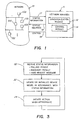
- Fig. 1 shows a network 10 having manageable devices, and a network manager 11 for providing control to the manageable devices 100 of the network 10.
- the network 10 may also include self-managing devices 102 as well as manageable devices 100. Additionally, the manageable devices 100 may be self-managing in some respects and manageable in other respects.
- SpectrumTM model-based network management system
- U.S. Patent No. 5,261,044 issued November 9, 1993 to R.Dev et al.
- the SpectrumTM network management system is commercially available and also described in various user manuals and literature available from Cabletron Systems, Inc., Rochester, New Hampshire.
- U.S. Patent Application Serial No. 08/188,238 entitled NETWORK HAVING SECURE FAST SWITCHING AND GUARANTEED QUALITY OF SERVICE describes techniques for establishing and controlling virtual connections through a communications network.
- the network manager includes a synchronization module 12 for determining the status of the manageable devices 100, and a control module 14 for providing appropriate control as described above.
- the synchronization module 12 receives status information 17 from the network, and provides status inquiries 18 to the network 10.
- the synchronization module 12 determines the status of the manageable devices of the network 10, and provides this status information to the control module 14.
- the control module 14 determines appropriate action to take, and provides the appropriate control 19 to the manageable devices of the network 10.
- the synchronization module may also provide control 19 to the devices of the network if such control is advantageous to achieving device-manager synchronization.
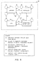
- Fig. 2 depicts detail of an embodiment of the synchronization module 12 of the network manager illustrated in Fig. 1.
- the synchronization module 12 includes a model control module 20 coupled to a network model 21 that includes device models 210A, 210B, 210C ... 210N.
- the model control module 20 is also coupled to each of a state machine 22, a polling manager 23, a discovery mechanism 25, and a reset mechanism 27.
- the model control module creates and maintains device models 210 that represent the status of manageable devices 100 of the network 10.
- the network model 21 may contain additional information, such as connectivity information with respect to the devices of the network 10. When the state of network model 21 matches the state of the actual network 10, the synchronization has been achieved.
- the control module 14 may then read the status of the device models 210 in order to determine appropriate control 19 to be provided to the network 10.
- the synchronization module 12 may be implemented as a software module, for example an object-oriented software module.
- the device models 210 may include an object representation for each device, wherein the object representation is indicative of the status of the device.
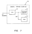
- the different sub-elements of the synchronization module 12 are implemented as software on a floppy disk or hard drive, which controls a computer, for example a general purpose computer such as a workstation, a mainframe or a personal computer, to perform steps of the disclosed processes such as those of Fig. 3 and Fig. 4.
- a general purpose computer 70 as shown in Fig. 7 typically includes a central processing unit 72 (CPU) coupled to random access memory 74(RAM) and program memory 76 via a data bus 78.
- the general purpose computer 70 may be connected to the network 10 in order to receive reports, and may provide commands to devices on the network in order to control the network configuration.
- the sub-elements of the synchronization module 12 may be implemented as special purpose electronic hardware. Additionally, in either a hardware or software embodiment, the functions performed by the different elements within the synchronization module 12 may be combined in varying arrangements of hardware and software.
- the network manager 11 receives status information 17 from the network 10 and provides a monitoring capability to determine the status of manageable devices within the network 10.
- the status information 17 may include a hardboot message, sent from a manageable device when the manageable device is initialized. This message, also called a "HELLO" message, may be sent to the network manager 10 from the manageable device's signaling mechanism only following a hard boot of the device.
- the receipt of such a message by the synchronization module 12 may be referred to as an initialization event (HE) with respect to the device 100 that sends the "HELLO" message.
- HE initialization event
- Such an initialization event (HE) facilitates the capability of the synchronization module 12 to distinguish between a hard boot of a device and a temporary loss of contact due to the device being too busy to respond to the manager 11.
- Another type of status information 17 includes a response by a device to a poll request by the synchronization module 12.
- the model control module 20 is coupled to a polling manager 23.
- the polling manager 23 provides poll requests 24 to devices of the network 10 to query the status of these devices.
- the polling manager may include an internal clock or timer to trigger the transmission of a poll request 24. In one embodiment, the polling frequency is approximately 10 seconds.
- a device may return a message indicative of contact being established between the network manager 11 and the device. The receipt by the synchronization module 12 of a message indicative of such a situation may be referred to as a "contact established" (CE) event.
- CE contact established
- a polled device may not respond to a poll request 24.
- the polling manager may determine that a predetermined amount of time has passed without receiving a response to a particular poll request 24, which is indicative of a "contact lost" (CL) event.
- the status information 17 may also include results from a discovery process.
- Discovery in this context, refers to querying the appropriate devices or ports of the devices directly to obtain information regarding their connectivity or other status.
- the discovery mechanism 25 may also include an entirely separate interface from that of the other status information 17 and status inquiries 18, and may use a standard management protocol such as SNMP (Simple Network Management Protocol).
- SNMP Simple Network Management Protocol
- the SNMP standard defines a set of variables that a device must keep to comply with SNMP, and includes adjacency information regarding other devices adjacent to the device being discovered.
- SNMP information typically includes three parts: structure of management information (SMI); management information base (MIB); and the SNMP protocol itself.
- the SMI and MIB define and store the set of managed entities as defined by the discovery mechanism 25, while the SNMP protocol enables information to be conveyed to and from the managed devices.
- the discovery mechanism 25 may exist as a separate off-the-shelf package.
- the model control module 20 may control the discovery mechanism 25 to perform such a discovery process.
- the discovery mechanism 25 provides discovery commands 26 to the appropriate devices of the network 10, and receives responses (as status information 17) to the discovery commands 26.
- the discovery mechanism 25 may also provide further discovery commands 26 based upon the results of earlier discovery commands. Accordingly, a discovery process may result in a "discovery successful" (DS) event in which the discovery mechanism 25 was able to acquire the desired information regarding a device, or a “discovery failure” (DF) event, in which a discovery process was not successfully completed with respect to a particular device.
- DS discovery successful
- DF "discovery failure"
- poll requests 24 and discovery commands 26 are included in the status inquiries 18 shown in Fig. 1. Additionally, other techniques may be used to acquire information regarding the status of devices within the network 10, and are meant to be within the scope of the term "status information.”
- a reset mechanism 27 may be controlled by the model control module 20 to provide a reset command 28 to a particular device.
- the reset command 28 is typically a control message sent to the device, and the device contains hardware and software that performs the reset.
- a reset in this context, refers to an initialization, for example an initialization of control parameters within the device. This is typically different from a hard reboot of the device, which sets all of the hardware and software of the device to a predetermined state. For example, a hard reboot typically results in a loss of data stored in random access memory (RAM), while a reset may maintain some of this data.
- RAM random access memory
- the model control module 20 receives status information 17.
- the status information 17 may include a polling result, a discovery result, a hard reboot message (e.g., "HELLO"), as well as other information.
- the actual reports that make up the status information 17 may be received directly by the polling manger 23 and the discovery mechanism 25, which in turn may provide appropriate messages to the model control module 20 to initiate the events, for example those described above (HE, CE, CL, DS, DF).
- the model control module 20 updates or initializes a device model 210 in accordance with the status information received in step 30.
- the model control module 20 initiates action, when appropriate, for example to gain more information regarding the status of a device.
- Fig. 4 shows more detail of steps 32 and 34 of Fig. 3.
- the previous state of a device is determined.
- Step 40 may be achieved by accessing a memory location that stores the status information of a device, or by querying a model such as the object- oriented model of the device models 210 described above.
- the new state of the device is determined based upon the previous state and the status information received in step 30.
- the new state may be one of a plurality of states that include an "unknown" state, an "initialized” state, a "lost” state, and an "established after lost" state.
- the plurality of states may include a different set of states, for example "up,” “down,” and “unknown.”
- the synchronization module 12 may more accurately represent the status of each device 100, and be less subject to lost messages or devices that are too busy to respond to queries.
- the "unknown" state of a device is indicative that the synchronization module 12 has no information regarding the status of the device. Often, in such a case, invoking the discovery mechanism may be the most effective manner in which to determine the status of such a device.
- the "initialized" state of a device is indicative that the device has been discovered and is ready to be controlled by the control module 14. This is typically the most common state of a device, because it is a state in which the device may be controlled by the control module 14.
- a device If a device is in the "lost" state, the device usually cannot be contacted. The device may have been too busy to respond to a status inquiry, or the device may have failed or been recently rebooted. Generally, actions are taken by the network manager 11 to work around the lost device, until information is received from the lost device indicative of the lost device changing status.
- a device In an "established after lost” state, a device may be contacted and is ready to be controlled by the control module 14. This state is similar to the "initialized” state, but is indicative that a successful discovery has not yet been performed with respect to the device.
- Step 42 may be performed through the use of the state machine 22 shown in Fig. 2.
- the state machine 22 may be implemented as a hardware machine as discussed earlier, or may be implemented in software as predetermined logic, as predetermined memory locations, or as a lookup table.
- the model control module 20 provides the previous state determined in step 40 and the status information received in step 30 to the state machine, and the state machine provides in response a new state that represents the current status of the device.
- Fig. 5 shows four different states including the unknown state 50, the initialized state 52, the lost state 54, and the established after lost state 56.
- Fig. 5 also shows the events described earlier (HE, DF, DS, CE, and CL), and the state change that takes place, if any, as a result of a particular event being received for a device that is in a particular state.
- the device model 210 is updated in accordance with the new state, or if the new state is the same as the old state, then no action may be taken. Additionally, the device model 210 may be enabled or disabled. Enabling and disable a device model 210 are actions which allow the control module 14 to know whether certain actions may be performed with respect to the device represented by the particular device model. When a device model 210 is disabled, for example, the control module 14 may avoid attempting to set up a connection through the device represented by the disabled device model 210. Instead, the control module 14 may instead attempt to use another device, for example, in order to provide an appropriate path for data. In summary, a disabled device model is indicative that the device is not usable by the control module 14, while an enabled device model is indicative that the device is usable by the control module 14.
- Steps 46 and 48 illustrate more detail of step 34 of Fig. 3.
- an appropriate action is determined based upon the previous state of a device and the status information received in step 30.
- This action includes action related to the synchronization of the device, and is typically different from the control of a device which is for the purposes of network control.
- the actions which may be taken include: initiating polling; triggering discovery; and providing a reset command. Each of these actions are described above with reference to Fig. 2.
- the state machine 22 may also be used to determine the action to take with respect to a device. As with the state change function of the state machine 22 described above, this function of the state machine 22 may be implemented in several ways, including accessing memory locations or lookup tables, for example.
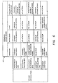
- Fig. 6 is a state table 60 which indicates the action to be taken in response to the synchronization module 12 receiving new device information about a device having a previous state.
- Four previous states are defined in the four columns, the four states being similar to the four states shown in Fig. 5.
- the rows of the state table 60 are indicative of the event, for example one of the events HE, DF, DS, CE, and CL.
- the intersection between the column representing the previous state of a device model 210 and the row representing the event indicated by the information received in step 30 shows the appropriate action.
- a device For example, if a device was previously in an unknown state and a discovery successful (DS) event is received with respect to the device, then the device would be reset and the model for that device would be enabled, so that the corresponding device in the network 10 could be controlled by the control module 14. Additionally, as shown in Fig. 5, in such a case the state of the device model would be changed from "unknown" to "initialized.”
- DS discovery successful
- a first example is how a network manager 11 synchronizes, during initialization, with the network devices 100 controlled by the network manager 11.
- the network manager 11 typically has information regarding at least one network device before initializing, so that the network manager 11 can perform discovery on this network device to learn about the remainder of the network 10.
- the network manager 11 When the network manager 11 is presented with a new device (the device could be a network address), it creates a device model 210 for that device and sets the device model 210 to the "unknown" state.
- the network manager 11 then invokes the discovery mechanism 25 on the device.
- the network manager 11 also registers the device with the polling mechanism 23 so it can appropriately monitor the device.
- the polling can be asynchronous with the discovery mechanism 25 so it is not guaranteed which event may be received from the manager's mechanisms first - the contact established (CE), or a-discovery successful (DS) or discovery failure (DF).
- CE contact established
- DS discovery failure
- the model control module 20 only the success from the discovery mechanism 25 (e.g., a DS event) will cause the model control module 20 to reset the device 100 and enable the device model 210, and transition the device model 210 to the "initialized" state.
- This state is the most common running state of the device model, and is indicative that the device 100 is now ready to be manipulated by the network manager 11.
- the only event which can remove the device model from the initialized state is a contact lost (CL) event.
- CE contact established
- a second example is a situation in which a network manager 11 is in synchronization with the manageable devices 100 of the network 11, but then one of the devices, for example a switch, hard resets for some reason.
- the device model of the device may be in the "initialized" state prior to the hard reset.
- the network manager's polling mechanism 23 discovers that it can not contact the device (because the device has recently had a hard reset), and thus sends a contact lost (CL) event to the model control module 20.
- the model control module 20 disables the model of the switch and transitions the model state to "lost."
- the synchronization module 12 may rediscover the switch because the devices adjacent to the switch may have changed from the time that the switch had a hard reset.
- the switch will be active, and the polling manager 23 will send a contact established (CE) event to the model control module 20.
- CE contact established
- the synchronization module 12 resets the switch so that the switch is initialized properly.
- the synchronization module 12 then enables the model of the switch, and sets the model state to "established after lost.”
- the switch will likely send the "HELLO" message, letting the synchronization model know that the switch was successfully reset, and may now be rediscovered.
- the model control module 20 disables the model of the switch and triggers the discovery mechanism 25.
- the device model 210 is disabled because after discovery is complete, the switch might be reset again for any of a number of reasons, for example by the control module 14. In such a situation, there should be no manipulation of the switch until after the reset, because all of the information that was just programmed into the switch by the control module 14 will be lost when it is reset.
- the switch model state is set to "initialized.”
- a device becomes too busy to respond and as a result, the polling mechanism 22 reports that it has lost contact with the particular network device by providing a CL event. Similar actions are performed as in the second example, but this time a "HELLO" message will not be received, because the device was not hard reset, and the associated device model will thus remain in the "established after lost” state. As was noted before, this state is similar to the "initialized” state, so that the device may be manipulated by the control module 14.
Abstract
Description
Claims (27)
- A method for determining a state of a device (100) in a communications network (10) comprising steps of:receiving a status report, including information regarding the device (100);determining a previous state of the device (100); andmaintaining a model of the device, based upon the previous state of the device (100) and the information regarding the device, wherein the step of maintaining includes setting a state of the model of the device to one of a predetermined plurality of states, the predetermined plurality of states including an established after lost state indicative that a successful discovery has not yet been performed with respect to the device.
- The method of claim 1, further comprising the step of querying the device (100) to provide additional information, and wherein the step of maintaining includes maintaining (32) the model (21) of the device (100) based upon a combination of the previous state of the device, the information regarding the device, and the additional information.
- The method of any of claims 1-2, wherein the step of receiving the status report (17) includes receiving a message indicative of a hard reboot of the device (100).
- The method of any of claims 1-3, wherein the step of receiving the status report (17) includes receiving results of a discovery process performed on the communications network (10).
- The method of claim 4, further comprising the step of initiating (48) the discovery process in response to a state of the model of the device (100).
- The method of any of claims 1-5, wherein the status report (17) includes results of a polling process.
- The method of claim 6, further comprising the step of initiating (48) the polling process in response to a state of the model (21) of the device (100).
- The method of any of claims 1-7, further comprising the step of providing (46) a reset command to the device (10) in response to a state of the model (21) of the device (100).
- The method of any of claims 1-8, wherein the step of maintaining (32) includes enabling the model to indicate that the device (100) is ready to be controlled by a network manager (11).
- The method of any of claims 1-9, wherein the step of maintaining (32) includes disabling the model to indicate that the device (100) is not ready to be controlled by a network manager (11).
- The method of any of claims 1-10, wherein the step of maintaining (32) includes the steps of:providing the previous state of the device and the information regarding the device (100) to a state machine (22);receiving an output of the state machine (22), the output being responsive to the previous state of the device and the information regarding the device (100); andmaintaining the model in accordance with the output of the state machine (22).
- The method of any of claims 1-11, wherein the predetermined plurality of states further includes:an unknown state (50) indicative that there is insufficient information to determine a capability of the device (100);an initialized state (52) indicative that the device (100) has been discovered and is ready to be controlled by a network manager, anda lost state (54) indicative that the device (100) was previously ready to be controlled but did not respond to a status inquiry.
- The method of any of claims 1-12, wherein the established after lost state (56) is further indicative that the device (100) has responded to a polling request (24) but has not fully responded to a discovery request for further status information relating to the device (100).
- An apparatus for determining a status of a device (100) in a communications network (10), the apparatus comprising:a model (21) of the device (100);a model control module (20) coupled to the model (21) of the device (100), the model control module (20) having an output that sets a state of the model of the device (100) to one of a predetermined plurality of states (50,52,54,56) representing the status of the device (100), the predetermined plurality of states including an established after lost state (56) indicative that a successful discovery has not yet been performed with respect to the device (100).
- The apparatus of claim 14, wherein:the model (21) of the device (100) contains information regarding a previous state of the device;the model control module (20) has an input that receives a status report (17) including information regarding the device (100); andthe output of the model control module (20) maintains the model (21) of the device (100) based upon a combination of the previous state of the device (100) and the information regarding the device (100).
- The apparatus of claim 15, further comprising a mechanism (23,25,27), coupled to the model control module (20), the mechanism (23,25,27) providing a query to the device so that the device (100) provides additional information, the model control module (20) maintaining the model (21) of the device (100) based upon a combination of the previous state of the device (100), the information regarding the device, and the additional information.
- The apparatus of any of claims 15-16, wherein the status report includes a message indicative of a hard reboot of the device (100).
- The apparatus of any of claims 15-17, wherein the status report includes results of a discovery process (26) performed on the communications network (10).
- The apparatus of any of claims 15-18, wherein the status report (17) includes results of a polling process.
- The apparatus of claim 19, further comprising a polling manager (23) coupled to the model control module (20) and the communications network (10), the polling manager (23) being responsive to the model control module (20) to initiate the polling process on the device (100).
- The apparatus of any of claims 15-20, further comprising a state machine (22) coupled to the model control module (20) and the model (21) of the device (100), the state machine (22) having a first input that receives the previous state of the device (100), a second input that receives the information regarding the device (100) to the state machine (22), and an output that provides information based upon which the model control module (20) maintains the model (21).
- The apparatus of any of claims 15-21, further comprising a discovery mechanism (23), coupled to the model control module (20) and the communications network (10), the discovery mechanism (25) being responsive to the model control module (20) to invoke a discovery process on the communications network (10).
- The apparatus of any of claims 14-22, further comprising a reset mechanism (27), coupled to the model control module (20) and the communications network (10), the reset mechanism being responsive to the model control module (20) to command a reset (28) of the device (100).
- The apparatus of any of claims 14-23, wherein the output of the model control module (20) enables the model (21) to indicate that the device (100) is ready to be controlled by a network manager (11).
- The apparatus of any of claims 14-23, wherein the output of the model control module (20) disables the model (21) to indicate that the device (100) is not ready to be controlled by a network manager (11).
- The apparatus of any of claims 14-25, wherein the predetermined plurality of states further includes:an unknown state (50) indicative that there is insufficient information to determine a capability of the device;an initialized state (52) indicative that the device has been discovered and is ready to be controlled by a network manager; anda lost state (54) indicative that the device was previously ready to be controlled but did not respond to a status inquiry.
- The apparatus of any of claims 14-26, wherein the established after lost state (56) is further indicative that the device (100) has responded to a polling request (24) but has not fully responded to a discovery request for further status information relating to the device (100).
Applications Claiming Priority (3)
| Application Number | Priority Date | Filing Date | Title |
|---|---|---|---|
| US08/577,429 US5734642A (en) | 1995-12-22 | 1995-12-22 | Method and apparatus for network synchronization |
| US577429 | 1995-12-22 | ||
| PCT/US1996/020081 WO1997023974A1 (en) | 1995-12-22 | 1996-12-19 | Method and apparatus for determining the status of a device in a communication network |
Publications (2)
| Publication Number | Publication Date |
|---|---|
| EP0868800A1 EP0868800A1 (en) | 1998-10-07 |
| EP0868800B1 true EP0868800B1 (en) | 2002-08-21 |
Family
ID=24308686
Family Applications (1)
| Application Number | Title | Priority Date | Filing Date |
|---|---|---|---|
| EP96944845A Expired - Lifetime EP0868800B1 (en) | 1995-12-22 | 1996-12-19 | Method and apparatus for determining the status of a device in a communication network |
Country Status (6)
| Country | Link |
|---|---|
| US (1) | US5734642A (en) |
| EP (1) | EP0868800B1 (en) |
| AT (1) | ATE222672T1 (en) |
| AU (1) | AU700957B2 (en) |
| DE (1) | DE69623127T2 (en) |
| WO (1) | WO1997023974A1 (en) |
Families Citing this family (50)
| Publication number | Priority date | Publication date | Assignee | Title |
|---|---|---|---|---|
| JP2950262B2 (en) * | 1996-11-29 | 1999-09-20 | 日本電気株式会社 | How to set up a multi-integrated agent system |
| US6052751A (en) * | 1997-02-14 | 2000-04-18 | Advanced Micro Devices, I Nc. | Method and apparatus for changing the number of access slots into a memory |
| US6125369A (en) * | 1997-10-02 | 2000-09-26 | Microsoft Corporation | Continuous object sychronization between object stores on different computers |
| US6633924B1 (en) | 1997-10-02 | 2003-10-14 | Charles Wu | Object synchronization between objects stores on different computers |
| JPH11122244A (en) * | 1997-10-20 | 1999-04-30 | Fujitsu Ltd | Managing device for large scaled network |
| JP3604898B2 (en) * | 1998-03-31 | 2004-12-22 | キヤノン株式会社 | Network device management apparatus and method, recording medium |
| US6308174B1 (en) | 1998-05-05 | 2001-10-23 | Nortel Networks Limited | Method and apparatus for managing a communications network by storing management information about two or more configuration states of the network |
| US6353612B1 (en) * | 1998-06-19 | 2002-03-05 | Brocade Communications Systems, Inc. | Probing device |
| US6360255B1 (en) * | 1998-06-25 | 2002-03-19 | Cisco Technology, Inc. | Automatically integrating an external network with a network management system |
| JP4105293B2 (en) * | 1998-06-30 | 2008-06-25 | 富士通株式会社 | Network monitoring system, monitoring device and monitored device |
| US6839757B1 (en) * | 1999-04-28 | 2005-01-04 | 2Wire, Inc. | System and method for automatically discovering accessible services on a computer network and providing automatic access thereto |
| US6584503B1 (en) | 1999-07-07 | 2003-06-24 | International Business Machines Corporation | Method, system and program for establishing network contact |
| JP4218152B2 (en) * | 1999-10-28 | 2009-02-04 | ソニー株式会社 | Communication method and communication system |
| JP4178697B2 (en) * | 1999-11-18 | 2008-11-12 | ソニー株式会社 | Portable information processing terminal, information input / output system, and information input / output method |
| US6694362B1 (en) * | 2000-01-03 | 2004-02-17 | Micromuse Inc. | Method and system for network event impact analysis and correlation with network administrators, management policies and procedures |
| US6748445B1 (en) * | 2000-02-01 | 2004-06-08 | Microsoft Corporation | System and method for exchanging data |
| US8396950B1 (en) * | 2000-03-02 | 2013-03-12 | Rockstar Consortium Us Lp | Method and apparatus for the fast detection of connectivity loss between devices in a network |
| AU2001261275A1 (en) * | 2000-05-05 | 2001-11-20 | Aprisma Management Technologies, Inc. | Systems and methods for isolating faults in computer networks |
| US7500143B2 (en) * | 2000-05-05 | 2009-03-03 | Computer Associates Think, Inc. | Systems and methods for managing and analyzing faults in computer networks |
| WO2001086775A1 (en) * | 2000-05-05 | 2001-11-15 | Aprisma Management Technologies, Inc. | Help desk systems and methods for use with communications networks |
| US7237138B2 (en) | 2000-05-05 | 2007-06-26 | Computer Associates Think, Inc. | Systems and methods for diagnosing faults in computer networks |
| US7752024B2 (en) * | 2000-05-05 | 2010-07-06 | Computer Associates Think, Inc. | Systems and methods for constructing multi-layer topological models of computer networks |
| US20070294409A1 (en) * | 2000-09-29 | 2007-12-20 | Arvind Kumar | Internet based network topology discovery |
| US7272644B1 (en) * | 2000-09-29 | 2007-09-18 | Intel Corporation | Internet based network topology discovery |
| US20050157654A1 (en) * | 2000-10-12 | 2005-07-21 | Farrell Craig A. | Apparatus and method for automated discovery and monitoring of relationships between network elements |
| US7383191B1 (en) * | 2000-11-28 | 2008-06-03 | International Business Machines Corporation | Method and system for predicting causes of network service outages using time domain correlation |
| US20020141351A1 (en) * | 2000-12-07 | 2002-10-03 | Maltz David A. | Method and system for validating network transformation instructions |
| US7797409B1 (en) * | 2001-01-26 | 2010-09-14 | Sobha Renaissance Information Technology | System and method for managing a communication network utilizing state-based polling |
| US20040044762A1 (en) * | 2001-02-22 | 2004-03-04 | Peacock Kimberly Roseanne | Methods and apparatus for controlling internet protocol traffic in a wan or lan |
| US6966015B2 (en) * | 2001-03-22 | 2005-11-15 | Micromuse, Ltd. | Method and system for reducing false alarms in network fault management systems |
| US6744739B2 (en) * | 2001-05-18 | 2004-06-01 | Micromuse Inc. | Method and system for determining network characteristics using routing protocols |
| US7043727B2 (en) * | 2001-06-08 | 2006-05-09 | Micromuse Ltd. | Method and system for efficient distribution of network event data |
| US7516208B1 (en) | 2001-07-20 | 2009-04-07 | International Business Machines Corporation | Event database management method and system for network event reporting system |
| US20030076809A1 (en) * | 2001-08-03 | 2003-04-24 | Coaxmedia, Inc. | Methods for detecting and polling downstream modems |
| US20050286685A1 (en) * | 2001-08-10 | 2005-12-29 | Nikola Vukovljak | System and method for testing multiple dial-up points in a communications network |
| US7139823B2 (en) * | 2001-08-23 | 2006-11-21 | International Business Machines Corporation | Dynamic intelligent discovery applied to topographic networks |
| US7085830B1 (en) | 2001-10-18 | 2006-08-01 | Network Equipment Technologies, Inc. | System and method to manage inconsistency problems between network management systems and network elements |
| US7363368B2 (en) | 2001-12-24 | 2008-04-22 | International Business Machines Corporation | System and method for transaction recording and playback |
| US7676606B1 (en) * | 2002-04-24 | 2010-03-09 | Cisco Technology, Inc. | Method and system for monitoring and controlling status of programmable devices |
| US7339484B2 (en) * | 2002-06-27 | 2008-03-04 | Hewlett-Packard Development Company, L.P. | Event-driven discovery method and apparatus |
| DE10251906B4 (en) * | 2002-11-07 | 2006-03-02 | Siemens Ag | Method and arrangement for the inventory of network components connected to a network |
| US20040162898A1 (en) * | 2003-02-14 | 2004-08-19 | Rich Jason H. | Dedicated networked device monitoring system |
| US20060005232A1 (en) * | 2004-06-30 | 2006-01-05 | Wilson Richard A Jr | Path utilization device discovery |
| US20060050716A1 (en) * | 2004-09-03 | 2006-03-09 | Intel Corporation | Generic flow control state machine for multiple virtual channel types in the advanced switching (AS) architecture |
| JP4576249B2 (en) * | 2005-01-27 | 2010-11-04 | 株式会社クラウド・スコープ・テクノロジーズ | Network management apparatus and method |
| US8060592B1 (en) * | 2005-11-29 | 2011-11-15 | Juniper Networks, Inc. | Selectively updating network devices by a network management application |
| JP4727715B2 (en) * | 2008-12-12 | 2011-07-20 | 株式会社日立製作所 | Stream data processing method and system |
| US9456356B2 (en) * | 2009-10-15 | 2016-09-27 | Apple Inc. | Methods for synchronizing data in a network |
| US8345660B2 (en) * | 2010-05-06 | 2013-01-01 | Digi International Inc. | Wireless mesh network controller synchronization |
| US9684499B2 (en) * | 2013-06-30 | 2017-06-20 | Dropbox, Inc. | Systems and methods for facilitating installation of software applications |
Family Cites Families (9)
| Publication number | Priority date | Publication date | Assignee | Title |
|---|---|---|---|---|
| JP3159979B2 (en) * | 1990-05-01 | 2001-04-23 | 株式会社日立製作所 | Network management display processing system and method |
| US5226120A (en) * | 1990-05-21 | 1993-07-06 | Synoptics Communications, Inc. | Apparatus and method of monitoring the status of a local area network |
| US5261044A (en) * | 1990-09-17 | 1993-11-09 | Cabletron Systems, Inc. | Network management system using multifunction icons for information display |
| AU645174B2 (en) * | 1991-03-15 | 1994-01-06 | Fujitsu Limited | Centralized supervisory system for transmission network elements and method of supervising transmission network elements |
| JP3160017B2 (en) * | 1991-08-28 | 2001-04-23 | 株式会社日立製作所 | Network management display device |
| WO1993010495A1 (en) * | 1991-11-22 | 1993-05-27 | Cabletron Systems, Inc. | Method and apparatus for monitoring the status of non-pollable devices in a computer network |
| US5535335A (en) * | 1992-12-22 | 1996-07-09 | International Business Machines Corporation | Method and system for reporting the status of an aggregate resource residing in a network of interconnected real resources |
| US5485455A (en) * | 1994-01-28 | 1996-01-16 | Cabletron Systems, Inc. | Network having secure fast packet switching and guaranteed quality of service |
| US5590120A (en) * | 1995-10-31 | 1996-12-31 | Cabletron Systems, Inc. | Port-link configuration tracking method and apparatus |
-
1995
- 1995-12-22 US US08/577,429 patent/US5734642A/en not_active Expired - Lifetime
-
1996
- 1996-12-19 EP EP96944845A patent/EP0868800B1/en not_active Expired - Lifetime
- 1996-12-19 AU AU13359/97A patent/AU700957B2/en not_active Ceased
- 1996-12-19 WO PCT/US1996/020081 patent/WO1997023974A1/en active IP Right Grant
- 1996-12-19 DE DE69623127T patent/DE69623127T2/en not_active Expired - Fee Related
- 1996-12-19 AT AT96944845T patent/ATE222672T1/en not_active IP Right Cessation
Also Published As
| Publication number | Publication date |
|---|---|
| WO1997023974A1 (en) | 1997-07-03 |
| US5734642A (en) | 1998-03-31 |
| EP0868800A1 (en) | 1998-10-07 |
| AU1335997A (en) | 1997-07-17 |
| ATE222672T1 (en) | 2002-09-15 |
| AU700957B2 (en) | 1999-01-14 |
| DE69623127D1 (en) | 2002-09-26 |
| DE69623127T2 (en) | 2003-05-15 |
Similar Documents
| Publication | Publication Date | Title |
|---|---|---|
| EP0868800B1 (en) | Method and apparatus for determining the status of a device in a communication network | |
| WO1997023974A9 (en) | Method and apparatus for determining the status of a device in a communication network | |
| US7017082B1 (en) | Method and system for a process manager | |
| US6097718A (en) | Snapshot routing with route aging | |
| US5287103A (en) | Method and apparatus for providing local area network clients with internetwork identification data | |
| US5852744A (en) | Method for discovering a network printer by assigning dedicated sockets to different printer types and polling the dedicated sockets to learn the corresponding state | |
| US6009274A (en) | Method and apparatus for automatically updating software components on end systems over a network | |
| US9270482B2 (en) | Method for activating a network component of a vehicle network system | |
| US6389129B1 (en) | Interface for interfacing client programs with network devices in a telecommunications network | |
| US7689678B2 (en) | Method and apparatus for restoring the configuration of a network device | |
| US20040003082A1 (en) | System and method for prevention of boot storms in a computer network | |
| JPH10313329A (en) | Fault permission communication method/system | |
| US20080205418A1 (en) | System and Method for Avoiding Duplication of MAC Addresses in a Stack | |
| US7308700B1 (en) | Network station management system and method | |
| US20230198881A1 (en) | Method and device for improving link aggregation protocol timeout | |
| JP3312595B2 (en) | Terminal connection control method and system in communication processing system composed of multiple processes | |
| Cisco | Configuring MPLS with the BPX Switch and the 6400/7200/7500 Routers | |
| Cisco | Managing Your Switches | |
| Cisco | Command Reference | |
| Cisco | Configuring MPLS on BPX Switch, 7200 and 7500 Series Routers | |
| Cisco | Using Terminals | |
| Cisco | Using Terminals | |
| Cisco | Using Terminals | |
| Cisco | The BPX Switch, 7200, and 7500 Routers for MPLS | |
| Cisco | Message and Recovery Procedures |
Legal Events
| Date | Code | Title | Description |
|---|---|---|---|
| PUAI | Public reference made under article 153(3) epc to a published international application that has entered the european phase |
Free format text: ORIGINAL CODE: 0009012 |
|
| 17P | Request for examination filed |
Effective date: 19980720 |
|
| AK | Designated contracting states |
Kind code of ref document: A1 Designated state(s): AT BE CH DE DK ES FI FR GB GR IE IT LI LU MC NL PT SE |
|
| GRAG | Despatch of communication of intention to grant |
Free format text: ORIGINAL CODE: EPIDOS AGRA |
|
| RTI1 | Title (correction) |
Free format text: METHOD AND APPARATUS FOR DETERMINING THE STATUS OF A DEVICE IN A COMMUNICATION NETWORK |
|
| 17Q | First examination report despatched |
Effective date: 20010613 |
|
| GRAG | Despatch of communication of intention to grant |
Free format text: ORIGINAL CODE: EPIDOS AGRA |
|
| GRAH | Despatch of communication of intention to grant a patent |
Free format text: ORIGINAL CODE: EPIDOS IGRA |
|
| RAP1 | Party data changed (applicant data changed or rights of an application transferred) |
Owner name: APRISMA MANAGEMENT TECHNOLOGIES, INC. |
|
| GRAH | Despatch of communication of intention to grant a patent |
Free format text: ORIGINAL CODE: EPIDOS IGRA |
|
| GRAA | (expected) grant |
Free format text: ORIGINAL CODE: 0009210 |
|
| AK | Designated contracting states |
Kind code of ref document: B1 Designated state(s): AT BE CH DE DK ES FI FR GB GR IE IT LI LU MC NL PT SE |
|
| PG25 | Lapsed in a contracting state [announced via postgrant information from national office to epo] |
Ref country code: NL Free format text: LAPSE BECAUSE OF FAILURE TO SUBMIT A TRANSLATION OF THE DESCRIPTION OR TO PAY THE FEE WITHIN THE PRESCRIBED TIME-LIMIT Effective date: 20020821 Ref country code: LI Free format text: LAPSE BECAUSE OF FAILURE TO SUBMIT A TRANSLATION OF THE DESCRIPTION OR TO PAY THE FEE WITHIN THE PRESCRIBED TIME-LIMIT Effective date: 20020821 Ref country code: IT Free format text: LAPSE BECAUSE OF FAILURE TO SUBMIT A TRANSLATION OF THE DESCRIPTION OR TO PAY THE FEE WITHIN THE PRE;WARNING: LAPSES OF ITALIAN PATENTS WITH EFFECTIVE DATE BEFORE 2007 MAY HAVE OCCURRED AT ANY TIME BEFORE 2007. THE CORRECT EFFECTIVE DATE MAY BE DIFFERENT FROM THE ONE RECORDED.SCRIBED TIME-LIMIT Effective date: 20020821 Ref country code: GR Free format text: LAPSE BECAUSE OF FAILURE TO SUBMIT A TRANSLATION OF THE DESCRIPTION OR TO PAY THE FEE WITHIN THE PRESCRIBED TIME-LIMIT Effective date: 20020821 Ref country code: FI Free format text: LAPSE BECAUSE OF FAILURE TO SUBMIT A TRANSLATION OF THE DESCRIPTION OR TO PAY THE FEE WITHIN THE PRESCRIBED TIME-LIMIT Effective date: 20020821 Ref country code: CH Free format text: LAPSE BECAUSE OF FAILURE TO SUBMIT A TRANSLATION OF THE DESCRIPTION OR TO PAY THE FEE WITHIN THE PRESCRIBED TIME-LIMIT Effective date: 20020821 Ref country code: BE Free format text: LAPSE BECAUSE OF FAILURE TO SUBMIT A TRANSLATION OF THE DESCRIPTION OR TO PAY THE FEE WITHIN THE PRESCRIBED TIME-LIMIT Effective date: 20020821 Ref country code: AT Free format text: LAPSE BECAUSE OF FAILURE TO SUBMIT A TRANSLATION OF THE DESCRIPTION OR TO PAY THE FEE WITHIN THE PRESCRIBED TIME-LIMIT Effective date: 20020821 |
|
| REF | Corresponds to: |
Ref document number: 222672 Country of ref document: AT Date of ref document: 20020915 Kind code of ref document: T |
|
| REG | Reference to a national code |
Ref country code: GB Ref legal event code: FG4D |
|
| REG | Reference to a national code |
Ref country code: CH Ref legal event code: EP |
|
| REF | Corresponds to: |
Ref document number: 69623127 Country of ref document: DE Date of ref document: 20020926 |
|
| REG | Reference to a national code |
Ref country code: IE Ref legal event code: FG4D |
|
| PG25 | Lapsed in a contracting state [announced via postgrant information from national office to epo] |
Ref country code: SE Free format text: LAPSE BECAUSE OF FAILURE TO SUBMIT A TRANSLATION OF THE DESCRIPTION OR TO PAY THE FEE WITHIN THE PRESCRIBED TIME-LIMIT Effective date: 20021121 Ref country code: DK Free format text: LAPSE BECAUSE OF FAILURE TO SUBMIT A TRANSLATION OF THE DESCRIPTION OR TO PAY THE FEE WITHIN THE PRESCRIBED TIME-LIMIT Effective date: 20021121 |
|
| PG25 | Lapsed in a contracting state [announced via postgrant information from national office to epo] |
Ref country code: PT Free format text: LAPSE BECAUSE OF FAILURE TO SUBMIT A TRANSLATION OF THE DESCRIPTION OR TO PAY THE FEE WITHIN THE PRESCRIBED TIME-LIMIT Effective date: 20021205 |
|
| ET | Fr: translation filed | ||
| PG25 | Lapsed in a contracting state [announced via postgrant information from national office to epo] |
Ref country code: LU Free format text: LAPSE BECAUSE OF NON-PAYMENT OF DUE FEES Effective date: 20021219 Ref country code: IE Free format text: LAPSE BECAUSE OF NON-PAYMENT OF DUE FEES Effective date: 20021219 |
|
| NLV1 | Nl: lapsed or annulled due to failure to fulfill the requirements of art. 29p and 29m of the patents act | ||
| PG25 | Lapsed in a contracting state [announced via postgrant information from national office to epo] |
Ref country code: ES Free format text: LAPSE BECAUSE OF FAILURE TO SUBMIT A TRANSLATION OF THE DESCRIPTION OR TO PAY THE FEE WITHIN THE PRESCRIBED TIME-LIMIT Effective date: 20030228 |
|
| REG | Reference to a national code |
Ref country code: CH Ref legal event code: PL |
|
| PLBE | No opposition filed within time limit |
Free format text: ORIGINAL CODE: 0009261 |
|
| STAA | Information on the status of an ep patent application or granted ep patent |
Free format text: STATUS: NO OPPOSITION FILED WITHIN TIME LIMIT |
|
| PG25 | Lapsed in a contracting state [announced via postgrant information from national office to epo] |
Ref country code: MC Free format text: LAPSE BECAUSE OF NON-PAYMENT OF DUE FEES Effective date: 20030701 Ref country code: DE Free format text: LAPSE BECAUSE OF NON-PAYMENT OF DUE FEES Effective date: 20030701 |
|
| 26N | No opposition filed |
Effective date: 20030522 |
|
| PG25 | Lapsed in a contracting state [announced via postgrant information from national office to epo] |
Ref country code: FR Free format text: LAPSE BECAUSE OF NON-PAYMENT OF DUE FEES Effective date: 20030901 |
|
| REG | Reference to a national code |
Ref country code: IE Ref legal event code: MM4A |
|
| REG | Reference to a national code |
Ref country code: FR Ref legal event code: ST |
|
| PGFP | Annual fee paid to national office [announced via postgrant information from national office to epo] |
Ref country code: GB Payment date: 20081217 Year of fee payment: 13 |
|
| GBPC | Gb: european patent ceased through non-payment of renewal fee |
Effective date: 20091219 |
|
| PG25 | Lapsed in a contracting state [announced via postgrant information from national office to epo] |
Ref country code: GB Free format text: LAPSE BECAUSE OF NON-PAYMENT OF DUE FEES Effective date: 20091219 |