EP0867870A1 - Optical disk apparatus and optical disk - Google Patents
Optical disk apparatus and optical disk Download PDFInfo
- Publication number
- EP0867870A1 EP0867870A1 EP98105538A EP98105538A EP0867870A1 EP 0867870 A1 EP0867870 A1 EP 0867870A1 EP 98105538 A EP98105538 A EP 98105538A EP 98105538 A EP98105538 A EP 98105538A EP 0867870 A1 EP0867870 A1 EP 0867870A1
- Authority
- EP
- European Patent Office
- Prior art keywords
- optical disk
- pits
- length
- radius
- marks
- Prior art date
- Legal status (The legal status is an assumption and is not a legal conclusion. Google has not performed a legal analysis and makes no representation as to the accuracy of the status listed.)
- Granted
Links
Images


Classifications
-
- G—PHYSICS
- G11—INFORMATION STORAGE
- G11B—INFORMATION STORAGE BASED ON RELATIVE MOVEMENT BETWEEN RECORD CARRIER AND TRANSDUCER
- G11B7/00—Recording or reproducing by optical means, e.g. recording using a thermal beam of optical radiation by modifying optical properties or the physical structure, reproducing using an optical beam at lower power by sensing optical properties; Record carriers therefor
- G11B7/24—Record carriers characterised by shape, structure or physical properties, or by the selection of the material
- G11B7/2407—Tracks or pits; Shape, structure or physical properties thereof
- G11B7/24085—Pits
-
- G—PHYSICS
- G11—INFORMATION STORAGE
- G11B—INFORMATION STORAGE BASED ON RELATIVE MOVEMENT BETWEEN RECORD CARRIER AND TRANSDUCER
- G11B7/00—Recording or reproducing by optical means, e.g. recording using a thermal beam of optical radiation by modifying optical properties or the physical structure, reproducing using an optical beam at lower power by sensing optical properties; Record carriers therefor
- G11B7/007—Arrangement of the information on the record carrier, e.g. form of tracks, actual track shape, e.g. wobbled, or cross-section, e.g. v-shaped; Sequential information structures, e.g. sectoring or header formats within a track
- G11B7/00718—Groove and land recording, i.e. user data recorded both in the grooves and on the lands
-
- G—PHYSICS
- G11—INFORMATION STORAGE
- G11B—INFORMATION STORAGE BASED ON RELATIVE MOVEMENT BETWEEN RECORD CARRIER AND TRANSDUCER
- G11B7/00—Recording or reproducing by optical means, e.g. recording using a thermal beam of optical radiation by modifying optical properties or the physical structure, reproducing using an optical beam at lower power by sensing optical properties; Record carriers therefor
- G11B7/24—Record carriers characterised by shape, structure or physical properties, or by the selection of the material
- G11B7/2403—Layers; Shape, structure or physical properties thereof
- G11B7/24035—Recording layers
- G11B7/24038—Multiple laminated recording layers
Definitions
- This invention relates to an optical disk apparatus which utilizes an optical disk as a recording medium, and more particularly to an optical disk apparatus using an optical disk on part or entire portion of which pits corresponding to data bits are previously recorded, for reproducing a data stream constructed by the pits by use of an optical head.
- a land/groove recording system is provided (for example, refer to Jpn. Pat. Appln. KOKOKU Publication No. 63-57859).
- the system is a system for recording marks, for example, phase-change marks on both of the land and groove and can make the recording density higher in comparison with a system for recording marks only on one of the land and groove.
- control information such as address data and a rotation control signal and other than rewritable data (user data and so on) in the case of hard format is generally previously recorded on the header field in the form of pre-pits.
- An area on which rewritable data is recorded is called a recording field for convenience to distinguish the recording field from the header field.
- the header field is provided only on the track of the land or groove.
- the header fields are provided on both of the tracks of the land and groove.
- crosstalk occurs due to the presence of the pits on the adjacent track when information is reproduced from the header field, thereby making it difficult to reproduce information in some cases.
- a land/groove recording system in which the pre-pit pattern of the header field is arranged shifting by a predetermined length in right and left with respect to the center of the track so that the pre-pit pattern is common to the land and groove.
- this system is used, the influence of crosstalk from the adjacent track can be reduced since the track pitch of pre-pits in the header field becomes twice that in the recording field.
- a reproduction system using a differential output signal (push-pull signal) from a two-segment split photo-detector can be effectively used.
- the off-track amount of the light beam spot can be detected by comparing the reproduced signal amplitudes of the pre-pit strings wobbled on the right and left sides.
- the modulation amplitude and asymmetry value of the reproduced signal of the header field are generally specified in the specification of the optical disk.
- the controllability of the symmetry in the eye-pattern of the reproduced signal based on the push-pull signal may depend on the cross section and the depth of a to-be-reproduced pit, but a clear standard is not specified. If the symmetry of the reproduced signal cannot be sufficiently controlled, the jitter of the reproduced signal becomes larger, thereby making it difficult to attain precise data reproduction.
- An object of this invention is to provide an optical disk apparatus capable of effecting the precise data reproduction of a header field by using a reproduction system for generating a push-pull signal obtained from a two-segment split photo-detector and specifying the structure of pits related to the symmetry control of a reproduction signal to attain the highly reliable symmetry control of the reproduction signal.
- an optical disk apparatus comprising an optical disk on which marks corresponding to data bits are arranged in a track tangential direction, a rotating unit for rotating the optical disk, and a reproducing unit for reproducing the marks, wherein the length PL of the marks is set at such a value as to satisfy a condition of following equation: 0.55 ⁇ (f T ⁇ PL)/(n ⁇ Sr1) ⁇ 1.50 where the scanning linear velocity at which the disk is rotated by the rotating unit when the reproducing unit reproduces the marks recorded in the radius r1 of the disk is set to Srl [m/s], a preset channel bit rate in the radius of the optical disk is set to f T [b/s], the marks correspond to data recorded in correspondence to the n-channel bit length, and the pit length in the track tangential direction is set to PL [m].
- the present invention provides an optical disk apparatus in which marks corresponding to data bits are recorded on the optical disk, a format having pit strings wobbled on both sides of the track center line of the recording field is provided, and the condition for recording the pits as described below is set when the beam spot is tracking-controlled along the track center line of the recording field and the data are reproduced using a push-pull signal obtained from a two-segment split photo-detector, thereby making it possible to obtain a reproduction signal with proper symmetry.
- PL is set to satisfy the condition expressed by the following expression. 0.55 ⁇ (f nT ⁇ PL)/(n ⁇ Srl) ⁇ 1.50
- the pit length PL is a pit length measured in the track tangential direction at the depth of pd/2 when the depth at the deepest portion of the pit is set to pd.
- the pit length PL in the case of the signal of the shortest length of pit and space (for example, 3T pit and space signal in the case of 8-16 modulation used in DVD) is required to be precisely set so as to satisfy the above expression based on the relation with the asymmetry.
- a reproduction signal of proper symmetry can be obtained by recording a pre-pit pattern with the pit length PL on the header field of the optical disk. Therefore, information can be reproduced from the header field with high reliability.
- an optical disk apparatus in which if the pit length in the track tangential direction at the depth of pd/2 is set to PLn [m] when the depth at the deepest portion of a pit which is recorded in the radius r1 of the optical disk and formed with a length corresponding to the code length nT in a preset modulation method is set to pd, a predetermined reproduction frequency of a 2 nT -pitch signal in the radius r1 is f nT [1/s], and the scanning linear velocity of the optical disk in the radius r1 is set to Sr1 [m/s], the condition expressed by the following expression is satisfied.
- PL 0.55 ⁇ (2 ⁇ f nT ⁇ PLn)/Srl ⁇ 1.50
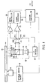
- the optical disk apparatus is a rewritable optical disk apparatus using the land/groove recording system, and as shown in FIG. 2, it is assumed that an optical disk on which control information or the like is recorded in the form of pre-pit pattern (pre-pit array) in the header field is used.
- the optical disk apparatus includes a spindle motor 11 for rotating an optical disk 10, a spindle motor driver 12 for driving the spindle motor 11, an optical head 13, a laser diode (LD) driver 18, an amplifier 21, a differential amplifier 25, a servo controller 22, a signal processor 26 and a system controller 28.
- a recording field and header field as shown in FIG. 2 are formed on the recording surface 20 of the optical disk 10.
- a recording field and header field as shown in FIG. 2 are formed in the header field.
- pits having such a structure as shown in FIG. 3 are recorded in a pre-pit string as will be described later.
- the optical head 13 includes a semiconductor laser 14, collimator lens 15, objective lens 16, actuator 17, polarization beam splitter 19, ⁇ /4 plate 29, condenser lens 23, and two-segment split photo-detector 24.
- the semiconductor laser 14 is driven by the LD driver 18 to emit a laser beam.
- the collimator lens 15 converts the laser beam from the semiconductor laser 14 into parallel light.
- the parallel light passes through the polarized beam splitter 19 and the ⁇ /4 plate 29, and is incident on the objective lens 16. Then, the objective lens 16 causes a light beam to be focused on the recording surface 20 of the optical disk 10.
- a signal indicating the amount of deviation of the light beam focused on the recording surface 20 from a target track in the radial direction and a signal indicating the amount of deviation of the light beam from the recording surface in the vertical direction are respectively output as a tracking error signal and focus error signal to the amplifier 21 by use of an optical/electrical system (not shown).
- the error signals amplified by the amplifier 21 are input to the servo controller 22.
- the servo controller 22 generates driving signals corresponding to the respective deviation amounts to drive and control the actuator 17 so as to change the position of the objective lens 16 and control the light beam spot to be applied to a target position.
- the light beam spot is controlled to be set on the center of each of a land 32 and groove 33 in the recording field of the optical disk.
- the light beam is first held in a corresponding radius immediately before the header field is scanned and then it is controlled to scan a position at a distance from the center of pre-pits 31 by an amount corresponding to half the track pitch of the recording field.
- the light beam reflected from the optical disk 10 passes through the ⁇ /4 plate 29 and is reflected by the polarization beam splitter 19 after passing through the objective lens 16 and is then made incident on the condenser lens 23.
- the light beam from the header field is converged on the two-segment split photo-detector 24 by the condenser lens 23.
- the two-segment split photo-detector 24 has two light receiving areas 24a and 24b divided with a separator 24c parallel to the track tangential direction on the optical disk set as the center as shown in FIG. 4.
- the two-segment split photo-detector 24 may be exclusively used for signal detection for the header field or may also be used for tracking error signal detection or RF signal detection.
- the differential amplifier 25 derives a difference signal (push-pull signal) based on output signals from the light receiving areas 24a and 24b and outputs the differential signal to the signal processor 26.
- the signal processor 26 effects the signal processing operation containing a preset demodulation process to generate a reproduction signal corresponding to the information recorded on the header field and output the same to the system controller 28.
- the main point of this invention is to set the length (pit length PL) of the pit in the track tangential direction among the structural factors of the pit so that the value of asymmetry AS which specifies the signal quality of the reproduction signal can be set to a desired degree (refer to FIG. 3).
- a method for quantitatively evaluating the signal quality of the reproduction signal a method for measuring the value of asymmetry AS which is an index indicating the degree of symmetry of the signal of the shortest length of pit and space and the signal of the longest length of pit and space of the pre-pit string is known.
- FIG. 5 is a diagram for illustrating the definition of the asymmetry AS of a reproduction signal waveform.
- the asymmetry AS can be expressed by the following equation (1) when the highest level and lowest level of a reproduction signal of the shortest length of pit and space (3T is the shortest length of pit and space) in the case of 8-16 modulation used in DVD, for example) of a certain modulation system are respectively set to IminH and IminL and the highest level and lowest level of a reproduction signal of the signal of the longest length of pit and space (14T is the longest length of pit and space) in the case of 8-16 modulation used in DVD, for example) are respectively set to ImaxH and ImaxL.
- nT indicates a time interval of the n-channel bits.
- AS [(Imax H + Imax L) - (Imin H + Imin L)]/[2(Imax H - Imax L)]
- other equation can be used to express the asymmetry value but they are substantially equal except for their polarity.
- the above specified range is preferably set to a range of -0.15 to 1.5 in the characteristic diagram shown in FIG. 6 when taking the margin of the physical characteristic of the optical disk and the manufacturing margin of the optical disk drive unit into consideration.
- FIG. 6 is a characteristic diagram showing the relation between the pit length PL and the value of asymmetry AS. That is, in the structure of the pre-pit 1 shown in FIG.
- the pit length PL in the track tangential direction of the signal of the shortest length of bit and space is closely related to the value of asymmetry AS of a push-pull signal when the pre-pit 1 is reproduced by use of the optical head 13 and is approximately inversely proportional to the AS.
- the push-pull signal is a difference signal of the two-segment split photo-detector 24 obtained at the time of reproduction of the pit when the light beam spot 34 of the optical head 13 is focused on a position with a preset offset in the radial direction from the pit center (refer to FIG. 2).
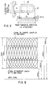
- FIG. 6 is a characteristic diagram of the value of asymmetry AS with respect to the pit length PL in the signal of the shortest length of pit and space in a case where the signal of the shortest length of pit and space is a cyclic signal having a pit pitch PP of 1.23 ⁇ m as shown in FIG. 8, the signal of the longest length of pit and space is a cyclic signal having a pit pitch PP of 5.74 ⁇ m as shown in FIG. 8, and the pit length in the signal of the longest length of pit and space is set at 2.87 ⁇ m in an optical system (optical head 13) in which the light source is 685 nm and the numerical aperture of the objective lens 16 is 0.6.
- an optical system optical head 13
- the characteristic curve 60A corresponds to the structure of the pit 1 having a rectangular cross section.
- the characteristic curve 60B corresponds to the structure of the pit 1 having a trapezoidal cross section and wall surface angles of approx. 30 degrees in both of the radial direction and track tangential direction as shown in FIG. 3.
- the pit depth pd is 90 nm.
- the pit length PL is the length of the pit in the track tangential direction in position at the depth of "pd/2" which is half the pit depth pd.
- FIG. 6 shows the characteristic curves 60B to 60E obtained when the wall surface angle ⁇ and the pit depth pd are changed with respect to the characteristic curve 60A obtained in a case where the pit has the rectangular cross section.
- the characteristic curve 60B shows a case wherein the wall surface angle ⁇ is approx. 30 degrees and the pit depth pd is 90 nm.
- the characteristic curve 60C shows a case wherein the wall surface angle ⁇ is approx.
- the characteristic curve 60D shows a case wherein the wall surface angle ⁇ is approx. 30 degrees and the pit depth pd is 70 nm.
- the characteristic curve 60E shows a case wherein the wall surface angle ⁇ is approx. 30 degrees and the pit depth pd is 30 nm.
- the characteristic curves 60A to 60E the characteristic curve is shifted more in the left direction in the graph as the pit depth pd is increased if the wall surface angle ⁇ is kept unchanged.
- the characteristic curve is shifted more in the left direction in the graph with the characteristic curve 60A of the rectangular case set as a reference as the wall surface angle ⁇ becomes smaller if the pit depth pd is kept unchanged.
- the characteristic curve of a pit having the wall surface angle ⁇ of not less than 30 degrees (not more than 90 degrees) and the pit depth of 90 nm or less varies in a range between the characteristic curves 60A and 60B which is indicated by a hatched portion in FIG. 6.
- a pit In a case where a pit is formed on the optical disk, it is realistic to form a pit having the wall surface angle ⁇ equal to or larger than approx. 30 degrees (not more than 90 degrees) and the pit depth pd of 90 nm or less in the above reproduction optical system when taking it into consideration that the amplitude of the difference signal becomes maximum at the optical depth of ⁇ /8 and becomes minimum at the depth of ⁇ /4.
- a cross section approximately equal to the rectangular cross section it is considered to set the pit depth pd deep to a value approximately equal to 3 ⁇ /8 or 5 ⁇ /8, and to not less than 90 nm but this is not substantially different from that in not more than 90 nm.
- the characteristic curve set in the range of hatched portion shown in FIG. 6 is assumed for the pit shape which can be practically considered and the pit length PL for the desired asymmetry AS is set. That is, the desired asymmetry AS is preferably set in the range of "-0.15 to 0.15" as described before. Therefore, as is clearly seen from FIG. 6, it is necessary to control the pit length PL in the range of "0.380 ⁇ m to 0.880 ⁇ m".
- FIG. 10 shows the pit length PL corresponding to the range of "-0.15 to 0.15" of the asymmetry AS for the respective characteristic curves 60A, 60B.
- the pit string is indicated by a single frequency signal having the pit pitch PP of 1.23 ⁇ m as shown in FIG. 8 and the pit scanning linear velocity is set to S [m/s], then the reproduction signal frequency f [1/s] of the single frequency signal is expressed by the following equation (2).
- f S/1.23 ⁇ 10 -6 [l/s]
- the operation for controlling the pit length PL in the range of "0.380 ⁇ m to 0.880 ⁇ m" is equivalent to the operation for controlling the pit length according to the following expression (3) 0.618 ⁇ (2 ⁇ f ⁇ PL)/S ⁇ 1.43
- the characteristic curves shown in FIG. 11 are obtained as the characteristic curves 60A, 60B of the pit length PL with respect to the asymmetry AS.
- the range of the pit length PL for the range of "-0.15 to 0.15" of the asymmetry AS becomes "0.302 ⁇ m to 0.745 ⁇ m". Therefore, if the calculation which is the same as that made when the pit pitch PP is 1.23 ⁇ m is made, the control operation equivalent to the operation for controlling the pit length PL based on the following expression (4) can be attained.
- 0.592 ⁇ (2 ⁇ f ⁇ PL)/S ⁇ 1.46 because f S/(1.02 ⁇ 10 -6 )
- the pit length PL which satisfies the following expression (6) instead of the expression (5) may be used. That is, the pit length PL of the pit recorded in correspondence to the n-channel bit length is set to satisfy the following expression (6) when the channel bit rate for the scanning linear velocity Sr1 [m/s] is set to fT [b/s]. 0.55 ⁇ (f T ⁇ PL)/(n ⁇ Sr1) ⁇ 1.50
- the asymmetry AS is set within a range of -0.15 to 0.15. However, this may be limited within a range of -0.10 to 0.10 in accordance with the margin allocation in the system.
- (2 ⁇ fnT ⁇ PLn)/Sr1) is set as follows. That is, the pit length PL is determined within a range of 0.445 ⁇ m to 0.827 ⁇ m for a single frequency signal having the pit pitch PP of 1.23 ⁇ m from FIG. 6. This range of the pit length corresponds to the following equation (7). 0.724 ⁇ (2 ⁇ f ⁇ PL)/S ⁇ 1.34
- the pit length PL which satisfies the following expression (10) instead of the expression (9) may be used. 0.65 ⁇ (f T ⁇ PL)/(n ⁇ Sr1) ⁇ 1.40
- a push-pull signal of desired asymmetry AS can be attained by use of the two-segment split photo-detector by setting the pit length PL to satisfy the above expression (5), (6), (9) or (10), particularly for each pit of the signal of the shortest length of pit and space when the pit is reproduced by focusing the beam spot on a position which is offset by a preset amount from the center of the pit in the radial direction.
- a reproduction signal of high quality can be obtained.
- the land/groove recording system is used in the recording field and the pre-pit array shown in FIG. 2 is used in the header field
- a reproduction signal of high quality can be obtained from the header field.
- the data recording density can be enhanced by use of the land/groove recording system, and at the same time, the reproducing operation with high precision for reproducing various information items from the pre-pit pattern in the header field with high reliability can be attained.
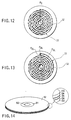
- FIGS. 12 and 13 show an optical disk of a single spiral format and an optical disk of a double spiral format, respectively.
- the single spiral format is a format wherein the land tracks 32 and groove tracks 33 are formed as a single spiral track from its start point P0 to its end point PE.
- the double spiral format is a format wherein the land track 32 and groove track 33 are formed as two parallel spiral tracks. In this double spiral format, there are two start points P0G and P0L and two end points PEG and PEL.
- the optical disk 10 is constructed by a double-sided disk as shown in FIG. 14. More specifically, the optical disk comprises two recording layers 54 adhered to each other by a adhesive layer between two substrates 53.
- the optical disk has a center hole 50 around which a clamp area 51 and readout area 52 are provided.
- the pre-pit 31, the land 32 and groove 33 are formed on the recording layer 54 of the optical disk as shown in FIG. 2.
- the above embodiment provides an optical disk on which the pits are formed.
- the marks may be formed on the optical disk instead of the pits.
- the pit structure which permits a push-pull signal of desired asymmetry AS to be obtained can be attained, particularly, in a case where a reproduction system using the push-pull signal obtained by the two-segment split photo-detector to reproduce data from the pre-pit array of the header field used. Therefore, particularly, when various information items are reproduced from the pre-pit pattern in the header field, a reproduction signal of high quality can be obtained and the reproducing operation of high reliability can be attained.
Abstract
Description
Claims (20)
- An optical disk apparatus characterized by comprising:an optical disk (10) on which marks corresponding to data bits are arranged in a track tangential direction;rotating means (11, 12) for rotating the optical disk; andreproducing means (13) for reproducing the marks,
wherein the length PL of each of the marks is set at such a value as to satisfy a condition of following equation: - The optical disk according to claim 1, characterized in that the marks are pits (31) recorded in the optical disk in the radius r1, the PL [m] indicates the length of each of the pits measured in the tangential direction of the track at a depth pd/2 where pd indicates a depth of a deepest portion of the pits.
- The optical disk apparatus according to claim 2, characterized in that the pits (1, 31) each have a trapezoidal cross section.
- The optical disk apparatus according to claim 2, characterized in that the pits (1, 31) having the trapezoidal cross section have a wall surface inclined by 30 to 75 degrees with respect to the track tangential direction and a depth of 30 nm to 90 nm.
- The optical disk apparatus according to claim 2, characterized in that the pits (1, 31) have a rectangular cross section.
- The optical disk apparatus according to claim 1, characterized in that n in the equation is defined as 4.
- An optical disk apparatus according to claim 1, characterized in that the reproducing means (13) includes means (14) for emitting a light beam spot having a maximum light intensity at a position having a given offset in the radius with respect to the center of each of the marks, to detect the marks on the optical disk; and
a two-segment split photo-detector (24) having a separator parallel to the track tangential direction to detect the marks by means of the light beam spot; and
means (25, 26) for reproducing the data on the basis of a difference signal from the two-segment split photo-detector. - An optical disk apparatus characterized by comprising:an optical disk (10) on which pits corresponding to bit data are pre-formed;rotating means (11, 12) for rotating the optical disk;reproducing means (13) including a two-segment split photo-detector (24) having a separator parallel to the track tangential direction to detect the pits by a reflected light obtained by emitting a light beam spot exhibiting a maximum light intensity peak at a position having a given offset in a radius with respect to a center of each of the pits, for reproducing data on the basis of a differential signal from the two-segment split photo-detector,
wherein a length of each of the pits is set at such a value as to satisfy a condition of following equation: - An optical disk apparatus according to claim 8, characterized in that the reproducing means includes means (14) for emitting the light beam spot to the optical disk to detect the pits thereon, and means (24, 25, 26) for reproducing the data on the basis of the differential signal from the two-segment split photo-detector.
- An optical disk on which a number of pits (31) corresponding to data bits to be reproduced by reproducing means are arrayed along a track tangential direction, characterized in that a length PL of each of the pits is set at such a value as to satisfy a condition of following equation:
- The optical disk according to claim 10, characterized in that the marks are formed of pits (31), and PL [m] indicates the length of each of the bits measured in a track tangential direction at a depth of pd/2 where pd indicates a depth of a deepest portion of each of the pits.
- The optical disk according to claim 11, characterized in that the pits each have a trapezoidal cross section.
- The optical disk according to claim 12, characterized in that the pits (1, 31) each have a wall surface inclined by 30 to 75 degrees with respect to the track tangential direction and a depth of 30 nm to 90 nm.
- The optical disk according to claim 10, characterized in that the marks are formed of pits (1, 31) each having a rectangular cross section.
- The optical disk according to claim 10, characterized in that n in the equation is defined as 4.
- An optical disk according to claim 10, characterized in that the reproducing means includes means (14) for emitting a light beam spot having a maximum light intensity at a position having a given offset in the radius with respect to a center of each of the marks, to detect the marks on the optical disk;
a two-segment split photo-detector (24) having a separator parallel to the track tangential direction to detect the marks by means of the light beam spot; and
means (25, 26) for reproducing the data on the basis of a difference signal from the two-segment split photo-detector. - An optical disk on which a number of pits (1, 31) corresponding to data bits to be reproduced by reproducing means (13) having a two-segment split photo-detector (24) and which is rotated by rotating means, characterized in that a length of each of the pits is set at such a value as to satisfy a condition of following equation:
- An optical disk on which marks (1, 31) corresponding to data bits are arranged in a track tangent direction, characterized by comprising:rotating means (11, 12) for rotating the optical disk; andreproducing means (13) for reproducing the marks,
wherein a length of each of the marks is set at such a value as to satisfy a condition of following equation: - An optical disk apparatus characterized by comprising:an optical disk (10) on which pits (1, 31) corresponding to bit data are pre-formed;rotating means (11, 12) for rotating the optical disk;reproducing means (13) including a two-segment split photo-detector (24) having a separator parallel to the track tangential direction to detect the pits by a reflected light obtained by emitting a light beam spot exhibiting a maximum light intensity peak at a position having a given offset in a radius with respect to a center of each of the pits, for reproducing data on the basis of a differential signal from the two-segment split photo-detector,
wherein a length PLn of each of the pits is set at such a value as to satisfy a condition of following equation: - An optical disk on which there are a number of pits (1, 31) corresponding to data bits to be reproduced by reproducing means (13) including means (14) for emitting a light beam spot having maximum light intensity at a position having a given offset in a radial direction with respect to a center of each of the pits to detect the pits on the optical disk and a two-segment split photo-detector (24), and which is rotated by rotating means, characterized in that a length of each of the pits is set at such a value as to satisfy a condition of following equation:
Priority Applications (1)
| Application Number | Priority Date | Filing Date | Title |
|---|---|---|---|
| EP04030060A EP1517311A3 (en) | 1997-03-26 | 1998-03-26 | Optical disk apparatus and optical disk |
Applications Claiming Priority (2)
| Application Number | Priority Date | Filing Date | Title |
|---|---|---|---|
| JP7343797 | 1997-03-26 | ||
| JP73437/97 | 1997-03-26 |
Related Child Applications (1)
| Application Number | Title | Priority Date | Filing Date |
|---|---|---|---|
| EP04030060A Division EP1517311A3 (en) | 1997-03-26 | 1998-03-26 | Optical disk apparatus and optical disk |
Publications (2)
| Publication Number | Publication Date |
|---|---|
| EP0867870A1 true EP0867870A1 (en) | 1998-09-30 |
| EP0867870B1 EP0867870B1 (en) | 2006-01-11 |
Family
ID=13518231
Family Applications (2)
| Application Number | Title | Priority Date | Filing Date |
|---|---|---|---|
| EP04030060A Withdrawn EP1517311A3 (en) | 1997-03-26 | 1998-03-26 | Optical disk apparatus and optical disk |
| EP98105538A Expired - Lifetime EP0867870B1 (en) | 1997-03-26 | 1998-03-26 | Optical disk apparatus and optical disk |
Family Applications Before (1)
| Application Number | Title | Priority Date | Filing Date |
|---|---|---|---|
| EP04030060A Withdrawn EP1517311A3 (en) | 1997-03-26 | 1998-03-26 | Optical disk apparatus and optical disk |
Country Status (8)
| Country | Link |
|---|---|
| US (1) | US6130871A (en) |
| EP (2) | EP1517311A3 (en) |
| CN (1) | CN1116672C (en) |
| AU (1) | AU6517798A (en) |
| ES (1) | ES2256902T3 (en) |
| MY (1) | MY120440A (en) |
| TW (1) | TW445450B (en) |
| WO (1) | WO1998043242A1 (en) |
Cited By (3)
| Publication number | Priority date | Publication date | Assignee | Title |
|---|---|---|---|---|
| EP1126444A2 (en) * | 2000-02-14 | 2001-08-22 | Sony Corporation | Optical recording medium and master disc for preparation thereof |
| EP1134734A2 (en) * | 2000-03-17 | 2001-09-19 | Kabushiki Kaisha Toshiba | Optical disc on which pre-pits are recorded |
| EP1028413A3 (en) * | 1999-02-09 | 2002-08-07 | Sony Corporation | Optical recording medium, stamper for use to produce the optical recording medium, and method of producing the stamper |
Families Citing this family (7)
| Publication number | Priority date | Publication date | Assignee | Title |
|---|---|---|---|---|
| JP2002184040A (en) * | 2000-12-15 | 2002-06-28 | Pioneer Electronic Corp | Optical disk |
| US20020093901A1 (en) * | 2001-01-16 | 2002-07-18 | Davies David H. | First-side dual-layer optical data storage disk and method of manufacturing the same |
| US6908725B2 (en) * | 2001-01-16 | 2005-06-21 | Dphi Acquisitions, Inc. | Double-sided hybrid optical disk with surface topology |
| US7368222B2 (en) * | 2001-01-16 | 2008-05-06 | Dphi Acquisitions, Inc. | Optical data storage media with enhanced contrast |
| KR100416594B1 (en) * | 2001-04-11 | 2004-02-05 | 삼성전자주식회사 | Apparatus for slice and slice level compensation of RF in the disc drive and method thereof |
| KR20050029765A (en) * | 2003-09-22 | 2005-03-28 | 삼성전자주식회사 | High density readable only optical disc and method for preparing the same |
| WO2006014152A1 (en) * | 2004-07-01 | 2006-02-09 | Midwest Research Institute | Optic probe for semiconductor characterization |
Citations (4)
| Publication number | Priority date | Publication date | Assignee | Title |
|---|---|---|---|---|
| EP0553541A1 (en) * | 1992-01-20 | 1993-08-04 | Pioneer Electronic Corporation | Optical disk and optical disk reproducing apparatus |
| EP0580873A1 (en) * | 1992-02-14 | 1994-02-02 | Sony Corporation | Information recording medium, and recording and reproducing device therefor |
| EP0664541A1 (en) * | 1994-01-19 | 1995-07-26 | Kabushiki Kaisha Toshiba | Optical disk and optical disk apparatus |
| US5477527A (en) * | 1994-02-02 | 1995-12-19 | Sanyo Electric Co., Ltd. | High density optical disc and optical disc player |
Family Cites Families (1)
| Publication number | Priority date | Publication date | Assignee | Title |
|---|---|---|---|---|
| JP2663817B2 (en) * | 1992-12-02 | 1997-10-15 | 松下電器産業株式会社 | Optical disk and optical disk device using the same |
-
1998
- 1998-03-25 TW TW087104472A patent/TW445450B/en not_active IP Right Cessation
- 1998-03-25 US US09/047,226 patent/US6130871A/en not_active Expired - Lifetime
- 1998-03-26 MY MYPI98001343A patent/MY120440A/en unknown
- 1998-03-26 EP EP04030060A patent/EP1517311A3/en not_active Withdrawn
- 1998-03-26 CN CN98804362A patent/CN1116672C/en not_active Expired - Lifetime
- 1998-03-26 AU AU65177/98A patent/AU6517798A/en not_active Abandoned
- 1998-03-26 ES ES98105538T patent/ES2256902T3/en not_active Expired - Lifetime
- 1998-03-26 EP EP98105538A patent/EP0867870B1/en not_active Expired - Lifetime
- 1998-03-26 WO PCT/JP1998/001338 patent/WO1998043242A1/en not_active Application Discontinuation
Patent Citations (4)
| Publication number | Priority date | Publication date | Assignee | Title |
|---|---|---|---|---|
| EP0553541A1 (en) * | 1992-01-20 | 1993-08-04 | Pioneer Electronic Corporation | Optical disk and optical disk reproducing apparatus |
| EP0580873A1 (en) * | 1992-02-14 | 1994-02-02 | Sony Corporation | Information recording medium, and recording and reproducing device therefor |
| EP0664541A1 (en) * | 1994-01-19 | 1995-07-26 | Kabushiki Kaisha Toshiba | Optical disk and optical disk apparatus |
| US5477527A (en) * | 1994-02-02 | 1995-12-19 | Sanyo Electric Co., Ltd. | High density optical disc and optical disc player |
Cited By (6)
| Publication number | Priority date | Publication date | Assignee | Title |
|---|---|---|---|---|
| EP1028413A3 (en) * | 1999-02-09 | 2002-08-07 | Sony Corporation | Optical recording medium, stamper for use to produce the optical recording medium, and method of producing the stamper |
| EP1126444A2 (en) * | 2000-02-14 | 2001-08-22 | Sony Corporation | Optical recording medium and master disc for preparation thereof |
| EP1126444A3 (en) * | 2000-02-14 | 2002-11-27 | Sony Corporation | Optical recording medium and master disc for preparation thereof |
| US6611492B2 (en) | 2000-02-14 | 2003-08-26 | Sony Corporation | Optical recording medium and master disc for preparation thereof |
| EP1134734A2 (en) * | 2000-03-17 | 2001-09-19 | Kabushiki Kaisha Toshiba | Optical disc on which pre-pits are recorded |
| EP1134734A3 (en) * | 2000-03-17 | 2002-08-14 | Kabushiki Kaisha Toshiba | Optical disc on which pre-pits are recorded |
Also Published As
| Publication number | Publication date |
|---|---|
| US6130871A (en) | 2000-10-10 |
| EP1517311A2 (en) | 2005-03-23 |
| TW445450B (en) | 2001-07-11 |
| EP1517311A3 (en) | 2008-02-13 |
| MY120440A (en) | 2005-10-31 |
| EP0867870B1 (en) | 2006-01-11 |
| WO1998043242A1 (en) | 1998-10-01 |
| CN1252880A (en) | 2000-05-10 |
| CN1116672C (en) | 2003-07-30 |
| ES2256902T3 (en) | 2006-07-16 |
| AU6517798A (en) | 1998-10-20 |
Similar Documents
| Publication | Publication Date | Title |
|---|---|---|
| US6990055B1 (en) | Optical disc drive for controlling reproduction of an optical disc having a plurality of data layers | |
| US6487147B2 (en) | Optical information recording medium and an optical information recording/reproduction device | |
| JPH09147393A (en) | Optical disk device and optical disk | |
| KR100330112B1 (en) | Optical disk and optical disk apparatus employing the same | |
| JP3560410B2 (en) | Optical disk device and optical disk | |
| KR20040018942A (en) | Optical disk apparatus | |
| US6130871A (en) | Optical disk apparatus and optical disk | |
| US7911907B2 (en) | Optical disc judgment method and optical disc device | |
| JPH09106579A (en) | Optical recording medium and method for reproducing preformat information and its reproducing device | |
| US6538963B1 (en) | Optical disk and recording/reproducing device thereof | |
| US6847594B1 (en) | Recording medium having wobbled groove tracks out of phase with wobbled land tracks, servo controlling apparatus using wobble signal and method thereof | |
| KR100378938B1 (en) | Optical disk device | |
| EP1026672B1 (en) | Recording medium having wobbled groove tracks out of phase with wobbled land tracks, servo controlling apparatus using wobble signal and method thereof | |
| JPH09251639A (en) | Optical disk and recording and reproducing device therefor | |
| JP2000076718A (en) | Magneto-optical recording medium | |
| US6661769B2 (en) | Optical storage medium, a tilt detection apparatus, and a data recording and reproducing apparatus | |
| JP3790037B2 (en) | Optical disk device and optical disk | |
| JP3513017B2 (en) | Optical recording medium and optical recording / reproducing apparatus using the same | |
| KR100628171B1 (en) | Method for recording/playing of optical recording medium and apparatus for the same | |
| US20030058757A1 (en) | Optical information recording medium and an optical information recording/reproduction device | |
| KR20010005658A (en) | Optical disk apparatus and optical disk | |
| US20030095489A1 (en) | Optical disk and optical disk drive | |
| MXPA99008760A (en) | Optical disk apparatus and optical disk | |
| KR100657695B1 (en) | Method and apparatus for controlling reference beam servo in holographic rom disk | |
| KR100263161B1 (en) | A deep groove high density optical disc preventing it from reversing the phase of tracking error signal |
Legal Events
| Date | Code | Title | Description |
|---|---|---|---|
| PUAI | Public reference made under article 153(3) epc to a published international application that has entered the european phase |
Free format text: ORIGINAL CODE: 0009012 |
|
| 17P | Request for examination filed |
Effective date: 19980423 |
|
| AK | Designated contracting states |
Kind code of ref document: A1 Designated state(s): CH ES FR GB GR IT LI NL SE |
|
| AX | Request for extension of the european patent |
Free format text: AL;LT;LV;MK;RO;SI |
|
| AKX | Designation fees paid |
Free format text: CH ES FR GB GR IT LI NL SE |
|
| REG | Reference to a national code |
Ref country code: DE Ref legal event code: 8566 |
|
| 17Q | First examination report despatched |
Effective date: 20030804 |
|
| GRAP | Despatch of communication of intention to grant a patent |
Free format text: ORIGINAL CODE: EPIDOSNIGR1 |
|
| GRAS | Grant fee paid |
Free format text: ORIGINAL CODE: EPIDOSNIGR3 |
|
| GRAA | (expected) grant |
Free format text: ORIGINAL CODE: 0009210 |
|
| AK | Designated contracting states |
Kind code of ref document: B1 Designated state(s): CH ES FR GB GR IT LI NL SE |
|
| REG | Reference to a national code |
Ref country code: CH Ref legal event code: EP |
|
| REG | Reference to a national code |
Ref country code: SE Ref legal event code: TRGR |
|
| REG | Reference to a national code |
Ref country code: GR Ref legal event code: EP Ref document number: 20060400139 Country of ref document: GR |
|
| REG | Reference to a national code |
Ref country code: ES Ref legal event code: FG2A Ref document number: 2256902 Country of ref document: ES Kind code of ref document: T3 |
|
| ET | Fr: translation filed | ||
| PLBE | No opposition filed within time limit |
Free format text: ORIGINAL CODE: 0009261 |
|
| STAA | Information on the status of an ep patent application or granted ep patent |
Free format text: STATUS: NO OPPOSITION FILED WITHIN TIME LIMIT |
|
| 26N | No opposition filed |
Effective date: 20061012 |
|
| REG | Reference to a national code |
Ref country code: CH Ref legal event code: PFA Owner name: KABUSHIKI KAISHA TOSHIBA Free format text: KABUSHIKI KAISHA TOSHIBA#72, HORIKAWA-CHO, SAIWAI-KU#KAWASAKI-SHI, KANAGAWA-KEN 210-8572 (JP) -TRANSFER TO- KABUSHIKI KAISHA TOSHIBA#72, HORIKAWA-CHO, SAIWAI-KU#KAWASAKI-SHI, KANAGAWA-KEN 210-8572 (JP) |
|
| REG | Reference to a national code |
Ref country code: FR Ref legal event code: PLFP Year of fee payment: 19 |
|
| REG | Reference to a national code |
Ref country code: FR Ref legal event code: PLFP Year of fee payment: 20 |
|
| PGFP | Annual fee paid to national office [announced via postgrant information from national office to epo] |
Ref country code: NL Payment date: 20170320 Year of fee payment: 20 Ref country code: CH Payment date: 20170314 Year of fee payment: 20 Ref country code: GR Payment date: 20170213 Year of fee payment: 20 Ref country code: SE Payment date: 20170313 Year of fee payment: 20 Ref country code: FR Payment date: 20170213 Year of fee payment: 20 |
|
| PGFP | Annual fee paid to national office [announced via postgrant information from national office to epo] |
Ref country code: GB Payment date: 20170322 Year of fee payment: 20 |
|
| PGFP | Annual fee paid to national office [announced via postgrant information from national office to epo] |
Ref country code: ES Payment date: 20170214 Year of fee payment: 20 Ref country code: IT Payment date: 20170320 Year of fee payment: 20 |
|
| REG | Reference to a national code |
Ref country code: NL Ref legal event code: MK Effective date: 20180325 |
|
| REG | Reference to a national code |
Ref country code: GB Ref legal event code: PE20 Expiry date: 20180325 |
|
| REG | Reference to a national code |
Ref country code: CH Ref legal event code: PL |
|
| PG25 | Lapsed in a contracting state [announced via postgrant information from national office to epo] |
Ref country code: GB Free format text: LAPSE BECAUSE OF EXPIRATION OF PROTECTION Effective date: 20180325 |
|
| REG | Reference to a national code |
Ref country code: SE Ref legal event code: EUG |
|
| REG | Reference to a national code |
Ref country code: ES Ref legal event code: FD2A Effective date: 20200902 |
|
| PG25 | Lapsed in a contracting state [announced via postgrant information from national office to epo] |
Ref country code: ES Free format text: LAPSE BECAUSE OF EXPIRATION OF PROTECTION Effective date: 20180327 |