EP0867151A2 - Medical laser irradiation apparatus - Google Patents
Medical laser irradiation apparatus Download PDFInfo
- Publication number
- EP0867151A2 EP0867151A2 EP98400687A EP98400687A EP0867151A2 EP 0867151 A2 EP0867151 A2 EP 0867151A2 EP 98400687 A EP98400687 A EP 98400687A EP 98400687 A EP98400687 A EP 98400687A EP 0867151 A2 EP0867151 A2 EP 0867151A2
- Authority
- EP
- European Patent Office
- Prior art keywords
- laser
- optical fiber
- irradiation apparatus
- irradiation
- fiber cable
- Prior art date
- Legal status (The legal status is an assumption and is not a legal conclusion. Google has not performed a legal analysis and makes no representation as to the accuracy of the status listed.)
- Granted
Links
Images


Classifications
-
- A—HUMAN NECESSITIES
- A61—MEDICAL OR VETERINARY SCIENCE; HYGIENE
- A61B—DIAGNOSIS; SURGERY; IDENTIFICATION
- A61B18/00—Surgical instruments, devices or methods for transferring non-mechanical forms of energy to or from the body
- A61B18/18—Surgical instruments, devices or methods for transferring non-mechanical forms of energy to or from the body by applying electromagnetic radiation, e.g. microwaves
- A61B18/20—Surgical instruments, devices or methods for transferring non-mechanical forms of energy to or from the body by applying electromagnetic radiation, e.g. microwaves using laser
- A61B18/22—Surgical instruments, devices or methods for transferring non-mechanical forms of energy to or from the body by applying electromagnetic radiation, e.g. microwaves using laser the beam being directed along or through a flexible conduit, e.g. an optical fibre; Couplings or hand-pieces therefor
-
- A—HUMAN NECESSITIES
- A61—MEDICAL OR VETERINARY SCIENCE; HYGIENE
- A61B—DIAGNOSIS; SURGERY; IDENTIFICATION
- A61B17/00—Surgical instruments, devices or methods, e.g. tourniquets
- A61B2017/00017—Electrical control of surgical instruments
- A61B2017/00132—Setting operation time of a device
-
- A—HUMAN NECESSITIES
- A61—MEDICAL OR VETERINARY SCIENCE; HYGIENE
- A61B—DIAGNOSIS; SURGERY; IDENTIFICATION
- A61B17/00—Surgical instruments, devices or methods, e.g. tourniquets
- A61B2017/00017—Electrical control of surgical instruments
- A61B2017/00199—Electrical control of surgical instruments with a console, e.g. a control panel with a display
-
- A—HUMAN NECESSITIES
- A61—MEDICAL OR VETERINARY SCIENCE; HYGIENE
- A61B—DIAGNOSIS; SURGERY; IDENTIFICATION
- A61B17/00—Surgical instruments, devices or methods, e.g. tourniquets
- A61B2017/00477—Coupling
- A61B2017/00482—Coupling with a code
-
- A—HUMAN NECESSITIES
- A61—MEDICAL OR VETERINARY SCIENCE; HYGIENE
- A61B—DIAGNOSIS; SURGERY; IDENTIFICATION
- A61B17/00—Surgical instruments, devices or methods, e.g. tourniquets
- A61B2017/00973—Surgical instruments, devices or methods, e.g. tourniquets pedal-operated
-
- A—HUMAN NECESSITIES
- A61—MEDICAL OR VETERINARY SCIENCE; HYGIENE
- A61B—DIAGNOSIS; SURGERY; IDENTIFICATION
- A61B18/00—Surgical instruments, devices or methods for transferring non-mechanical forms of energy to or from the body
- A61B18/18—Surgical instruments, devices or methods for transferring non-mechanical forms of energy to or from the body by applying electromagnetic radiation, e.g. microwaves
- A61B18/20—Surgical instruments, devices or methods for transferring non-mechanical forms of energy to or from the body by applying electromagnetic radiation, e.g. microwaves using laser
- A61B2018/2065—Multiwave; Wavelength mixing, e.g. using four or more wavelengths
-
- A—HUMAN NECESSITIES
- A61—MEDICAL OR VETERINARY SCIENCE; HYGIENE
- A61B—DIAGNOSIS; SURGERY; IDENTIFICATION
- A61B18/00—Surgical instruments, devices or methods for transferring non-mechanical forms of energy to or from the body
- A61B18/18—Surgical instruments, devices or methods for transferring non-mechanical forms of energy to or from the body by applying electromagnetic radiation, e.g. microwaves
- A61B18/20—Surgical instruments, devices or methods for transferring non-mechanical forms of energy to or from the body by applying electromagnetic radiation, e.g. microwaves using laser
- A61B2018/208—Surgical instruments, devices or methods for transferring non-mechanical forms of energy to or from the body by applying electromagnetic radiation, e.g. microwaves using laser with multiple treatment beams not sharing a common path, e.g. non-axial or parallel
-
- A—HUMAN NECESSITIES
- A61—MEDICAL OR VETERINARY SCIENCE; HYGIENE
- A61B—DIAGNOSIS; SURGERY; IDENTIFICATION
- A61B18/00—Surgical instruments, devices or methods for transferring non-mechanical forms of energy to or from the body
- A61B18/18—Surgical instruments, devices or methods for transferring non-mechanical forms of energy to or from the body by applying electromagnetic radiation, e.g. microwaves
- A61B18/20—Surgical instruments, devices or methods for transferring non-mechanical forms of energy to or from the body by applying electromagnetic radiation, e.g. microwaves using laser
- A61B18/22—Surgical instruments, devices or methods for transferring non-mechanical forms of energy to or from the body by applying electromagnetic radiation, e.g. microwaves using laser the beam being directed along or through a flexible conduit, e.g. an optical fibre; Couplings or hand-pieces therefor
- A61B2018/2205—Characteristics of fibres
- A61B2018/2211—Plurality of fibres
Definitions
- the present invention relates to diagnostic and treating equipment in the medical field, and more particularly to a medical laser irradiation apparatus suitably used for displaying different effects through the use of a plurality of laser wavelengths.
- a laser device capable of outputting a laser wavelength answering the purpose is selected.
- a laser beam in a range from a visible region to a near infrared region, which shows a relatively deep penetration property is suitable.
- a laser beam in an infrared region which shows shallow penetration property, is more effective.
- a laser beam in an ultraviolet region is appropriate for observing a fluorescence for a medical purpose.
- a laser guiding means such as an optical fiber may be coupled to an apparatus equipped with at least one laser oscillator to guide a laser beam to a given place.
- the laser irradiation apparatus is provided with laser oscillators corresponding to different wavelengths, and if at least one of the laser wavelengths is within an ultraviolet region below 300 nm or within an infrared region above 2.5 ⁇ m, as the laser guiding means, in addition to a general-purpose quartz optical fiber, an ultraviolet or infrared dedicated optical fiber may be used.
- Fig. 9 is an illustration of one example of an arrangement serving as medical laser irradiation apparatus for making laser beam irradiation having two or more wavelengths as mentioned above, which was devised by this inventor at the same time.
- numeral 100 represents a laser irradiation apparatus
- 101 designates a quartz optical fiber
- numeral 120 denotes a fluoride optical fiber
- numeral 102 depicts an output setting switch
- numeral 103 stands for a laser wavelength selector switch
- numeral 104 signifies a display for displaying the output power or a set irradiation time
- numeral 105 indicates a foot switch for performing a laser irradiation
- numeral 106 shows an emergency shutdown (safety) switch.
- Fig. 100 represents a laser irradiation apparatus
- 101 designates a quartz optical fiber
- numeral 120 denotes a fluoride optical fiber
- numeral 102 depicts an output setting switch
- numeral 103 stands for a laser wavelength selector
- numeral 110 represents an Nd : YAG laser serving as a first laser oscillating section for outputting a laser beam 111 with a first wavelength of 1.064 ⁇ m
- numeral 112 designates an Er : YAG laser acting as a second laser oscillating section for outputting a laser beam 113 with a second wavelength of 2.94 ⁇ m
- numeral 114 denotes a fixed reflecting mirror
- numeral 115 depicts a movable reflecting mirror
- numeral 116 signifies a focusing lens.
- the laser oscillating section 110 is chosen through the wavelength selector switch 103 so that the movable reflecting mirror 115 is put at a position expressed at numeral 115a and the laser oscillating section 110 assumes a waiting condition.
- the operator steps on the foot switch 105 to put the laser oscillating section 110 into operation, thereby emitting the laser beam 111 with the wavelength of 1.064 ⁇ m.
- the laser beam 111 is reflected by the fixed reflecting mirror 114 to a different optical path to be incident on the focusing lens 116 and then incident on the optical fiber 101 to be transmitted to the tip portion of the optical fiber 101 and applied onto the irradiation place.
- the light-guiding optical fiber is replaced with the fluoride optical fiber 120, and the laser oscillating section 112 is chosen through the wavelength selector switch 103 so that the movable reflecting mirror 115 is put at a position designated at numeral 115b and the laser oscillating section 112 goes into a waiting condition. Subsequently, the foot switch 105 is stepped on so that the laser oscillating section 112 beigins oscillation.
- the laser beam 113 with the wavelength of 2.94 ⁇ m outputted from the laser oscillating section 112 undergoes the optical path change due to the movable reflecting mirror 115 to be incident on the focusing lens 116 and further incident on the optical fiber 101 to be transmitted to the tip portion of the optical fiber 101 and applied onto the irradiation place.
- the medical laser irradiation apparatus in the case of emitting a laser beam from an optical fiber the laser beams of a plurality of wavelengths included as the irradiation laser wavelengths within an ultraviolet region below 300 nm or within an infrared region above 2.5 ⁇ m, a plurality of laser oscillating sections capable of outputting the aforesaid laser wavelengths are required to be provided within the apparatus, so that the apparatus becomes considerably bulky and costly. Further, a special-purpose optical fiber is needed in addition to the general-purpose quartz optical fiber.
- the length of the light-guiding optical fiber must extend from the apparatus up to the laser irradiation target, and hence, becomes extremely longer when compared with the different medical device extending from the target place to the vicinity of the user outside the living body. This creates a serious problem in practical use.
- each optimal wavelength laser source must be provided with an laser irradiation apparatus for the excitation of the solid laser medium and/or the wavelength conversion by the nonlinear optical element, and there is no interchangeability between the laser irradiation apparatus and the optical fiber cable containing the nonlinear optical crystal and/or the solid state laser medium.
- the laser irradiation apparatus and the optical fiber cable be paired for every output laser wavelength.
- the present invention has been developed to eliminating the foregoing problems, and it is an object of this invention to provide a medical laser irradiation apparatus which is capable of conveniently supplying laser beams with two or more kinds of wavelengths including a wavelength in an ultraviolet region below 300 nm or in an infrared region above 2.5 ⁇ m through the use of one apparatus.
- a laser irradiation apparatus features the following arrangement.
- a medical laser irradiation apparatus including a laser irradiation apparatus and at least two irradiation optical fiber cables coupled to the laser irradiation apparatus;
- the irradiation optical fiber cables comprise quartz optical fibers used as light guiding paths, and a solid state laser medium and/or a nonlinear optical crystal capable of generating a laser beam with a wavelength which is substantially difficult to guide through the quartz optical fibers are set on tip portions of the quartz optical fibers; and the laser irradiation apparatus is equipped with laser generating means capable of generating laser beams of a plurality of wavelengths which are transmittable through the quartz optical fibers and a laser beam emitting opening.
- a laser beam with a wavelength suitable for the excitation of the solid state laser medium or for a wavelength conversion by the nonlinear optical crystal is selectively guided through the interiors of the irradiation optical fiber cables, and the laser beams of at least two wavelengths which can not be guided through the quartz optical fibers are emitted from the tip portions of the irradiation optical fiber cables.
- a laser irradiation apparatus when, for example, an irradiation optical fiber cable having, at its tip portion a nonlinear optical crystal capable of outputting a laser beam whose wavelength is below 300 nm, an irradiation optical fiber cable having, at its tip portion, a solid state laser medium capable of outputting a laser beam whose wavelength is above 2.5 ⁇ m, or an irradiation optical fiber cable comprising a quartz optical fiber are coupled to a laser irradiation apparatus, the laser beam led through the irradiation optical fiber cable is switched to have a wavelength suitable in accordance with the kind of the irradiation optical fiber cable, and a laser beam with a wavelength below 300 nm or above 2.5 ⁇ m or a diode laser beam with a near infrared wavelength suitable as a laser light source for the laser irradiation apparatus can be emitted from the different irradiation optical fiber cable tip portions.
- a quartz optical fiber By only selecting the kind of the irradiation optical fiber cable to be used, laser beams of a plurality of wavelengths including a laser beam in a wavelength region failing to effectively transmit (to be guided) through a quartz optical fiber can be emitted from the irradiation optical fiber cable tip portion through one small-sized medical laser irradiation apparatus. It becomes possible to perform the diagnosis using an ultraviolet laser beam, the solidification using a near infrared laser beam and the transpiration using an infrared laser beam. In addition, since all the irradiation optical fiber cables have a quartz optical fiber as a light guiding path, a relay optical fiber cable comprising a quartz optical fiber is insertable into between the irradiation optical fiber cable and the laser irradiation apparatus.
- a means to detect the type of each optical fiber cable is placed at the connection section between two or more irradiation optical fiber cables and the laser irradiation apparatus or the relay optical fiber cable. The result is that the necessary laser beam can be safely emitted without connecting an irradiation optical fiber cable in error.
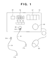
- Fig. 1 is an illustration of an arrangement of amedical laser irradiation apparatus according to a first embodiment of this invention, which can emit a laser beam with a wavelength assuming any one of 970 nm, 2.8 ⁇ m or 275.5 nm by reconnecting three kinds of irradiation optical fiber cables.
- numeral 40 represents a laser irradiation apparatus internally including a diode laser light source for a wavelength of 970 nm and a control circuit for taking the charge of the lighting control of the diode laser.
- a temperature control unit capable of adjusting the wavelength in a range of 10 nm by changing or altering the temperature of the diode laser light source.
- the aforesaid diode laser light source is mounted on a Peltier device 92 equipped with the radiation fins 91.
- the Peltier device 92 is made to vary the quantity of heat generated in response to a given current value, and the heat generated by this Peltier device 92 heats or cools the diode laser light source 90.
- the Peltier device 92 is provided with a temperature monitoring thermister 93. The temperature monitored by this thermister 93 is feedbacked to a temperature control unit 94 which internally include a driver circuit for the Peltier device 92 to control the temperature of the Peltier device 92, thus, the diode laser light source 90.
- the diode laser light source 90 is made, for example, so that the wavelength of a laser beam outputted varies by 0.3 nm when the temperature varies by 1°C, and when the temperature variation of ⁇ 20°C occurs, the wavelength of the laser beam outputted can vary by ⁇ 6 nm.
- Numeral 41 denotes one of the irradiation optical fiber cables, and a solid state laser oscillating section capable of producing a light beam with a wavelength of 2.8 ⁇ m is integrally attached to a tip portion 41a of a quartz optical fiber, while the other end portion is equipped with a connector 41b for connection with a laser irradiation apparatus 40.
- the connector 41b has a projection which identify the irradiation optical fiber cable 41.
- Numeral 51 depicts a different one of the irradiation optical fiber cables, and a solid state laser medium capable of generating a laser beam with a wavelength of 551 nm and a nonlinear optical crystal are integrally provided at a tip portion 51a of a quartz fiber, whereas the other end portion is equipped with a connector 51b for establishing a connection with the laser irradiation apparatus 40.
- a connector 51b On the connector 51b, includes a projection which can identify the irradiation optical fiber cable 51.
- Numeral 42 signifies a receptacle for making a connection of any one of the aforesaid three kinds of irradiation optical fiber cables in the laser irradiation apparatus 40, which has a mechanism to detect the fiber type identifying projection in the connector 41b at the connection of the irradiation optical fiber cable.
- Numerals 43, 44 and 45 designate indicators for indicating the connected one of the aforesaid three kinds of irradiation optical fiber cables on the basis of an identification signal from the detection mechanism.
- the indicator 44 corresponds to the irradiation optical fiber cable having, at its tip portion, the solid state laser oscillating section capable of generating the laser beam with a wavelength of 2.8 ⁇ m.
- the indicator 44 is for the irradiation optical fiber cable having, at its tip portion, the solid state laser medium capable of generating a laser beam with a wavelength of 551 nm and a wavelength converting device comprising a nonlinear optical crystal.
- the indicator 45 is for the irradiation optical fiber cable comprising a quartz optical fiber.
- Numeral 48 denotes a switch and lamp device for indicating the allowance of the laser irradiation.
- Numeral 46 depicts an output setting switch for selecting the laser output level and an irradiation waveform.
- Numeral 47 signifies a display section for displaying the contents set through the setting switch 46.
- Numeral 50 represents a foot switch for the ON/OFF control of the laser output.
- Numeral 49 designates an emergency shutdown switch, with all operation stopping when depressing this switch 49.
- Fig. 3 is an illustration of a cross section of the tip portion 41a of the irradiation optical fiber cable 41.
- numeral 70 represents aquartz optical fiber
- numeral 22 denotes a diode laser beam whose wavelength is 967 nm.
- numeral 71 designates a focusing lens of the diode laser beam 22
- numeral 72 depicts a YSGG crystal where Er is doped by 30% as a solid state laser medium capable of generating a laser beam with a wavelength of 2.8 ⁇ m.
- numeral 75 represents a sleeve for fixedly positioning the optical fiber 70, the focusing lens 71 and the solid state laser medium 72
- numeral 76 stands for an output laser beam whose wavelength is 2.8 ⁇ m.
- Fig. 4 is an illustration of the tip portion of the irradiation optical fiber cable 51.
- numeral 80 represents a quartz optical fiber
- numeral 22 designates a diode laser beam with a wavelength of 975 nm
- numeral 82 denotes a focusing lens for the diode laser beam
- numeral 83 depicts a YLF crystal where Er is doped by 5% as a solid state laser medium capable of generating a laser beam with a wavelength of 551 nm.
- Numeral 85 signifies a ⁇ -BaB 2 O 4 serving as a nonlinear optical crystal for converting the laser beam wavelength of 551 nm into a beam of 275.5 nm.
- numeral 87 depicts a sleeve for fixedly positioning the quartz optical fiber 80, the focusing lens 82, the solid state laser medium 83 and the nonlinear optical crystal 85
- numeral 84 stands for a laser beam whose wavelength is 551 nm
- numeral 86 designates an output laser beam whose wavelength is 275.5 nm.
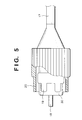
- Fig. 5 is an illustration of one example of structures of the connector 41b in Fig. 1.
- numeral 17 signifies an irradiation optical fiber cable
- numeral 18 is a ferrule
- numeral 30 designates a fitting component for fixedly positioning the ferrule 18 at a central position and further for connecting it to the receptacle 42.
- numeral 19 represents a projection section attached or formed integrally to or with the fitting component 30, with the projection section 19 having different configurations or assuming a given number of projections in accordance with the types of irradiation optical fiber cables in order to identify the different irradiation optical fiber cables.
- the receptacle 42 is equipped with a mechanism to detect the configurations of the projection section 19.
- Numeral 20 denotes a screw section for fixing the irradiation optical fiber cable to the laser irradiation apparatus 40.
- Fig. 6 is an illustration of examples of configurations of the projections 19 for identifying three kinds of irradiation optical fiber cables, in the connect or exemplified in Fig. 5.
- Fig. 7 is an illustration of one example of mechanisms for detecting the kinds of the irradiation optical fiber cables, in the receptacle 42 shown in Fig. 1.
- numeral 60 represents a receptacle body
- numeral 61 is an irradiation optical fiber cable fixing screw section.
- Numeral 62 designates a slide section which shifts by depressing the Fig. 4 projection section 19 in the irradiation optical fiber cable connector and which is placed at a portion where the screw section 61 is partially cut off.
- Numeral 63 depicts a spring for pushing out the slide section 62 at aconstant length
- numeral 64 denotes a switch which operates when the slide section 62 is pushed in by the connector projection section 19.
- the connector 41b has identifying projections such as a configuration indicated by numeral 19a in Fig. 5; the projection section 19a pushes down the corresponding portion of the slide section 62 (Fig. 7), the corresponding portion of the switch 64 turns ON; thereby detecting the connection of the irradiation optical fiber cable 41.
- the temperature control unit 94 adjusts the temperature of the diode laser light source placed within the laser irradiation apparatus 40 to a temperature for generating a 967nm laser beam which provides the highest efficiency when the solid state laser medium 72 produces a laser beam with a wavelength of 2.8 ⁇ m.
- the laser output mode, the output value and the irradiation time are set through the output setting switch 46 in Fig. 1 to appropriate values, and these values are displayed on the display section 47.
- the output mode signifies the moduration waveform of the irradiation laser beam intensity.
- irradiation optical fiber cable is connectable to the receptacle 42 irrespective of its type, since the type of irradiation optical fiber cable can be automatically identified by means of the aforesaid detection mechanism. Accordingly, in the case of employing the irradiation optical fiber cable 51 with a solid state laser medium capable of generating a laser beam with a wavelength of 551 nm and the nonlinear optical crystal are provided integrally at the tip portion of the quartz optical fiber as shown in Fig.
- the temperature control unit 94 alters the temperature of the diode laser light source provided within the laser irradiation apparatus 40 to a temperature for generating a 975nm laser beam which provides the highest efficiency when the solid state laser medium 83 produces a laser beam whose wavelength is 551 nm.
- the laser output mode, the output value and the irradiation time are set to appropriate values through the use of the output setting switch 46 in Fig. 1, and these values are displayed on the display section 47.
- the switch 48 On depressing the switch 48, after the completion of the setting of the output setting switch 46, a lamp integrated with this switch 48 lights, and after the aforesaid control circuit conforms that there is no malfunction, the laser irradiation waiting condition is entered. In this waiting condition, if the foot switch 50 in Fig. 1 is activated, a laser beam with a wavelength of 275.5 nm is outputted from the tip portion 51a of the irradiation optical fiber cable 51.
- this laser irradiation apparatus when using an irradiation optical fiber cable comprising a quartz optical fiber without any material at the tip porion, for example, if setting the identifying projection section in the aforesaid connector section to the 19c configuration shown in Fig. 5, the connection with the irradiation optical fiber cable is detected through the receptacle 42. Simultaneously with the indicator 45 going on, the wavelength of the diode laser light source placed within the laser irradiation apparatus 40 is altered to 970 nm.
- the laser output mode, the output value and the irradiation time are set to appropriate values through the use of the output setting switch 46, and these values are displayed on the display section 47. If the switch 48 is depressed after the completion of the setting of the output setting switch 46, a lamp integrated with this switch 48 goes on, and after the aforesaid control circuit confirms that there is no malfunction, a laser irradiation ready condition is entered. In this ready condition, if the foot switch 50is activated, a laser beam with a wavelength of 970 nm is emitted from the tip portion of the irradiation optical fiber cable.
- the wavelength of the diode laser light source 90 is variable by varying the temperature of the diode laser 90, for example, the selection thereof is possible in a range of 965 nm to 975 nm.
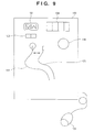
- Fig. 8 shows an arrangement of a medical laser irradiation apparatus according to a second embodiment of this invention.
- numeral 80 represents a relay optical fiber cable comprising a quartz optical fiber
- numeral 80a designates a receptacle which is positioned at the tip portion of the relay optical fiber cable 80 and which is equipped with a mechanism to detect the type of connection sections of irradiation optical fiber cables as shown in Fig. 7 and to relay this infomation to the laser irradiation apparatus 40, for example, by using an electric signal.
- the operation of the medical laser irradiation apparatus according to the second embodiment constructed as mentioned above is basically similar to that of the above-described first embodiment, and the same components are marked with the same numerals and the description thereof will be omitted for brevity.
- a feature of this embodiment is to employ the relay optical fiber cable 80, and all the three kinds of irradiation optical fiber cables mentioned in the first embodiment are made such that the quartz optical fiber is used as a light guiding path, they can be connected to the receptacle 80a at the tip portion of the relay optical fiber cable 80.
- the irradiation laser beam wavelength setting when using an irradiation optical fiber cable can be done in the same way as that of the first embodiment.
- the length of the irradiation optical fiber cable used in this embodiment can be shortened as compared with the first embodiment because of using the relay optical fiber cable between the laser irradiation apparatus and the irradiation optical fiber cable.
- one relay optical fiber cable 80 is used therefore, laser beams of at least two wavelengths which can not transmit in a quartz optical fiber can be emitted from the tip portion of the irradiation optical fiber cable by replacing the type of the irradiation cable.
- one diode laser is used as the laser light source provided in the laser irradiation apparatus
- other light sources are acceptable as long as they can generate a laser beam with a wavelength conforming to the type of the irradiation optical fiber cable to be connected to the laser irradiation apparatus, for instance, a wavelength variable laser such as a titanium-sapphire laser is suitable.
- a wavelength variable laser it is also possible to use a laser in a band of 800 nm as a laser wavelength for transmitting in the irradiation optical fiber cable, and hence, in the above-described first and second embodiments, a cable having an Nd : YAG solid state laser crystal and two nonlinear optical crystals at its tipportion can be used as the aforesaid irradiation optical fiber cable capable of emitting an ultraviolet laser beam.
- one laser light source is internally included in the laser irradiation apparatus, it is also appropriate to provide a plurality of laser light sources generating laser beams of a plurality of kinds of wavelengths.
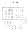
- Fig. 11 shows a medical laser irradiation apparatus according to a third embodiment of this invention.
- numeral 1 represents a laser irradiation apparatus which internally includes a diode laser light source for a wavelength of 970 nm.
- numeral 2 designates a quartz optical fiber as a first optical fiber cable for irradiation
- numeral 3 denotes a second optical fiber cable for irradiation, with a solid state laser oscillating section capable of generating a laser beam with a wavelength of 2.8 ⁇ m is integrally placed at the tip portion 3a of a quartz optical fiber.
- numeral 4 depicts a third optical fiber cable for irradiation, with a solid state laser oscillating section capable of generating a laser beam with a wavelength of 551 nm and a wavelength converting section are integrally located at the tip portion 4a of a quartz optical fiber.
- Numerals 5, 6 and 7 signify receptacles for the connection of the optical fiber cables 2, 3 and 4, respectively, in the laser irradiation apparatus, the receptacles being equipped with fitting sections having different configurations and with means to present erroneous combinations from being used, described herein later.
- Numeral 8 represents a selection switch for the optical fiber cables 2, 3, 4, and numerals 9, 10, 11 designate light-emitting lamp type indicators for indicating the optical fiber cables 2, 3, 4 selected through the selection switch 8.
- Numeral 12 denotes a lamp and switch device for indicating the allowance of the laser irradiation
- numeral 13 depicts an output setting switch for selecting the laser output and the moduration waveform
- numeral 14 signifies a display section for displaying the value set by the setting switch 13.
- numeral 15 represents a foot switch which activates the laser to provide an output at an arbitrary timing when the operator steps on the switch.
- numeral 16 represents an emergency shutdown switch, where all operations stop in response to the depression of the switch 16.
- the solid state laser oscillating section is integrally placed at the tip portion of the optical fiber cable 3 as mentioned before. Its structure is the same as that of the structure of the tip portion 41a of the irradiation optical fiber cable 41 in the first embodiment shown in Fig. 3.
- the solid state laser oscillating section and the wavelength converting section comprising a nonlinear optical crystal integrally located at the tip portion of the optical fiber cable 4.
- the structure is the same as the structure of the tip portion 51a of the irradiation optical fiber cable 51 in the first embodiment shown in Fig. 4.
- connection sections of the optical fiber cables 2, 3, 4 to be fitted in the receptacles 5, 6, 7 in Fig. 11 are the same as that in the first embodiment shown in Fig. 5.
- the configurations of the projection section 19 for identifying the optical fiber cables 2, 3, 4 are also the same as those in the first embodiment shown in Fig. 6.
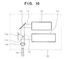
- Fig. 12 shows a mechanism for switching the laser beam to the optical cables for use in the interior of the laser irradiation apparatus 1.
- numeral 21 is a diode laser light source
- numeral 22 designates a laser beam generated from the diode laser light source 21.
- Numerals 23, 24, 25 denote reflecting mirrors, and of these reflecting mirrors, the mirrors 24, 25 are equipped with a moving means.
- Numerals 26, 27, 28 depict focusing lenses for condensing the laser beam 22 reflected on the reflecting mirrors 23, 24, 25 to focus them on the optical fiber cables 2, 3, 4.
- Numeral 29 signifies a control circuit which controls the position of the reflecting mirror 24 or 25 in accordance with the kind of the optical fiber cable selected through the optical fiber cable selection switch 8 to switch the optical path of the laser beam 22, and further controls the temperature of the diode laser 21 to perform the wavelength adjustment when necessary.
- the control circuit 29 receives the input from the output setting switch 13 and controls the driving condition of the diode laser 21 to generate the laser output or the irradiation waveform displayed on the display section 14.
- the laser output mode, the output value and the irradiation time are set to appropriate values through the use of the output setting switch 13, and these values are displayed on the display section 14.
- the output mode means the moduration waveform of the irradiation laser beam intensity.
- the switch 12 If the switch 12 is pushed down after the completion of the setting of the optical fiber cable selection switch 8 and the output setting switch 13, the lamp integrated with the switch 12 lights up, and after the control circuit 29 in Fig. 12, confirms no malfunction, the laser irradiation waiting condition is taken.
- the waiting condition when the foot switch 15 in Fig. 11 is activated, a laser beam with a wavelength of 970 nm is generated by the diode laser 21 and outputted from the tip portion of the optical fiber cable 2.
- the laser irradiation apparatus if setting the optical fiber cable selection switch 8 to the optical fiber cable 3, the lamp of the indicator 10 goes on, and the reflecting mirror 24 moves in a position to reflect the laser beam 22 so that the optical path selection causees the laser beam to use the optical fiber cable 3.
- the laser output mode, the output value and the irradiation time are displayed on the display section 14 and set to appropriate values through the output setting switch 13.
- the diode laser 21 functions as an exciting light source for the solid state laser medium 72 (see Fig. 3) integrally placed at the tip portion of the optical fiber cable 3, the value for the laser output 76 (see Fig. 3) as a wavelength of 2.8 ⁇ m to be emitted from the solid state laser oscillating section 3a is displayed on the display section 14, and the control is performed by the control circuit 29 with respect to the output of the diode laser 21.
- the oscillation wavelength of the diode laser 21 is altered to 967 nm which causes the solid state laser medium 72 to generate a laser beam with a wavelength of 2.8 ⁇ m at high efficiency.
- the switch 12 When the switch 12 is pushed down after the completion of the setting of the optical fiber cable selection switch 8 and the output setting switch 13, the lamp integral with the switch 12 turns on, and the control circuit 29 confirms no malfunction, thereafter going into the laser irradiation waiting condition. While in this waiting condition, if the foot switch 15 is activated, the solid state laser medium 72 is excited by the diode laser beam 22, so that the laser beam 76 with the wavelength of 2.8 ⁇ m is outputted from the tip portion of the optical fiber cable 3.
- the laser irradiation apparatus if the optical fiber cable selection switch 8 is set to the optical fiber cable 4, the lamp of the indicator 11 goes on, and the reflecting mirror 25 moves to a position to reflect the laser beam 22 so that the optical path selection selects the use of the optical fiber cable 4.
- the laser output mode, the output value and the irradiation time are displayed on the display section 14 and set to appropriate values through the output setting switch 13.
- the diode laser 21 functions as an exciting light for the solid state laser medium 83 (see Fig. 4) integrally placed at the tip portion of the optical fiber cable 4, the value for the laser output (see Fig. 4) with a wavelength of 275.5 nm to be emitted from the wavelength converting section 4a is displayed on the display section 14.
- Control is performed by the control circuit 29 with respect to the output of the diode laser 21, and the oscillation wavelength of the diode laser 21 is altered to provide an output of 975 nm which can cause the solid state laser medium 83 generate a laser beam with a wavelength of 551 nm with the high efficiency.
- the switch 12 When the switch 12 is pushed down after the completion of the setting of the optical fiber cable selection switch 8 and the output setting switch 13, the lamp integral with the switch 12 goes on, and the control circuit 29 confirms no malfunction, thereafter coming into the laser irradiation waiting condition.
- the solid state laser medium 83 In this waiting condition, if foot switch 15 is activated, the solid state laser medium 83 is excited by the diode laser beam 22 so that the laser beam 84 with the wavelength of 551 nm is generated and the wavelength of the laser beam 84 is converted through the nonlinear optical crystal 85 to 1/2 the input wavelength, and the laser beam 86 with a wavelength of 275.5 nm is outputted from the tip portion of the optical fiber cable 4.
- the connectors for making the connection of the optical fiber cables 2, 3, 4 to the laser irradiation apparatus 1 are respectively provided with the projections indicated at 19a, 19b, 19c in Fig. 6, the receptacles 5, 6, 7 in the laser irradiation apparatus 1 are respectively equipped with fitting sections corresponding to the projection sections 19a, 19b, 19c, and therefore, the optical fiber cables 2, 3, 4 are respectively exclusively connectable with the receptacles 5, 6, 7.
- At least two irradiation optical fiber cables including one having a solid state laser medium and/or a nonlinear optical crystal at their tip portions are used for outputting laser beams of a plurality of wavelengths capable of being transmitted in the quartz optical fiber, and therefore, it is possible to emit laser beams of at least two wavelengths, for example, in an ultraviolet region or in a wavelength region above 2.5 ⁇ m, which are hard to transmit in an quartz optical fiber, by the irradiation optical fiber cable tip portion.
- a relay optical fiber cable comprising a general-purpose quartz optical fiber
- mechanism which identifies the above-mentioned two or more kinds of irradiation optical fiber cables, thus, it is possible to ensure the safe use of the laser irradiation apparatus without connecting erroneous irradiation optical fiber cables, and hence, the practical effects greatly improve, thus greatly contributing to a wider application of the medical laser irradiation apparatus.
- the medical laser irradiation apparatus equipped with a diode laser light source, if two or more types of optical fiber cables including one having the solid state laser medium and/or the nonlinear optical crystal at their tip portions are used with one laser generating means, it is possible to generate laser beams with wavelengths corresponding to the types of optical fiber cables.
Abstract
Description
Claims (11)
- A medical laser irradiation apparatus including a laser irradiation apparatus and at least two irradiation optical fiber cables coupled to said laser irradiation apparatus when used; wherein said irradiation optical fiber cables comprise quartz optical fibers to be used as light guiding paths, and a solid state laser medium and/or a nonlinear optical crystal capable of generating a laser beam with a wavelength which is substantially difficult to guide through said quartz optical fibers, are set on tip portion of said quartz optical fibers; and said laser irradiation apparatus is equipped with laser beam generating means capable of generating laser beams of a plurality of wavelengths which are transmittable through said quartz optical fibers and a laser beam emitting opening; such that, in accordance with kinds of said irradiation optical fiber cables connected to said laser irradiation apparatus, a laser beam with a wavelength suitable for excitation of said solid state laser medium or for wavelength conversion by said nonlinear optical crystal is selectively guided into the interiors of said irradiation optical fiber cables; and laser beams of at least two wavelengths, which are substantially difficult to guide through said quartz optical fibers, are emitted from tip portions of said irradiation optical fiber cables.
- A medical laser irradiation apparatus according to claim 1, further comprising detecting means for detecting the kind of said irradiation optical fiber cable connected to said laser irradiation apparatus, and changing means for changing a wavelength of a laser beam to be outputted from said laser irradiation apparatus on the basis of the kind of said irradiation optical fiber cable.
- A medical laser irradiation apparatus according to claim 1, wherein said laser beam generating means includes a diode laser.
- A medical laser irradiation apparatus according to claim 1, further comprising a relay optical fiber cable composed of quartz optical fiber, said relay optical fiber cable being provided between said laser irradiation apparatus and said irradiation optical fiber cable.
- A medical laser irradiation apparatus according to claim 4, further comprising detecting means for detecting the kind of said irradiation optical fiber cable connected to said relay optical fiber cable and changing means for changing a wavelength of a laser beam to be outputted from said laser irradiation apparatus on the basis of the kind of said irradiation optical fiber cable.
- A medical laser irradiation apparatus according to claim 1, wherein said laser generating means includes one laser light source and drive means for generating laser beams of a plurality of wavelengths from said laser light source.
- A medical laser irradiation apparatus according to claim 6, wherein said one laser light source is composed of a diode laser, and said drive means is equipped with temperature changing means for changing the temperature of said diode laser.
- A medical laser irradiation apparatus according to claim 7, wherein said temperature altering means includes a Peltier device and a current value altering circuit for changing the current to be supplied to said Peltier device.
- A medical laser irradiation apparatus according to claim 8, further comprising temperature detecting means for monitoring the temperature of said Peltier device.
- A medical laser irradiation apparatus according to claim 6, wherein said one laser light source is a titanium-sapphire laser.
- A medical laser irradiation apparatus according to claim 1, wherein said laser beam generating means is equipped with a plurality of laser light sources for generating laser beams having different wavelengths.
Applications Claiming Priority (3)
| Application Number | Priority Date | Filing Date | Title |
|---|---|---|---|
| JP72384/97 | 1997-03-25 | ||
| JP7238497 | 1997-03-25 | ||
| JP7238497 | 1997-03-25 |
Publications (3)
| Publication Number | Publication Date |
|---|---|
| EP0867151A2 true EP0867151A2 (en) | 1998-09-30 |
| EP0867151A3 EP0867151A3 (en) | 2000-08-02 |
| EP0867151B1 EP0867151B1 (en) | 2005-11-16 |
Family
ID=13487746
Family Applications (1)
| Application Number | Title | Priority Date | Filing Date |
|---|---|---|---|
| EP98400687A Expired - Lifetime EP0867151B1 (en) | 1997-03-25 | 1998-03-25 | Medical laser irradiation apparatus |
Country Status (3)
| Country | Link |
|---|---|
| US (1) | US5993442A (en) |
| EP (1) | EP0867151B1 (en) |
| DE (1) | DE69832315T2 (en) |
Cited By (7)
| Publication number | Priority date | Publication date | Assignee | Title |
|---|---|---|---|---|
| EP1124613A1 (en) * | 1996-09-04 | 2001-08-22 | Mark D. Gart | Photodynamic therapy method and apparatus |
| WO2002015808A1 (en) * | 2000-08-23 | 2002-02-28 | Meister Joerg | Medical laser treatment module |
| WO2001097912A3 (en) * | 2000-06-21 | 2002-06-20 | Raymond A Hartman | Targeted uv phototherapy apparatus and method |
| WO2004010885A1 (en) * | 2002-07-25 | 2004-02-05 | Diomed Inc. | Laser system |
| EP1471613A2 (en) * | 2003-04-25 | 2004-10-27 | Nidek Co., Ltd. | Medical laser apparatus |
| EP1872755A1 (en) * | 2006-06-30 | 2008-01-02 | Alcon Inc. | Apparatus and system for steering an optical beam |
| EP2118971A1 (en) * | 2007-02-21 | 2009-11-18 | Cao Group, Inc. | Modular laser transmission systems |
Families Citing this family (16)
| Publication number | Priority date | Publication date | Assignee | Title |
|---|---|---|---|---|
| US6110195A (en) * | 1998-06-01 | 2000-08-29 | Altralight, Inc. | Method and apparatus for surgical and dermatological treatment by multi-wavelength laser light |
| US6267779B1 (en) * | 1999-03-29 | 2001-07-31 | Medelaser, Llc | Method and apparatus for therapeutic laser treatment |
| US20060052865A1 (en) * | 2004-09-09 | 2006-03-09 | Banas Christopher E | Stents with metallic covers and methods of making same |
| US6673095B2 (en) * | 2001-02-12 | 2004-01-06 | Wound Healing Of Oklahoma, Inc. | Apparatus and method for delivery of laser light |
| MXPA03009992A (en) | 2001-05-03 | 2005-03-07 | Advanced Light Technology Llc | Differential photochemical & photomechanical processing. |
| US7303578B2 (en) | 2001-11-01 | 2007-12-04 | Photothera, Inc. | Device and method for providing phototherapy to the brain |
| US10695577B2 (en) | 2001-12-21 | 2020-06-30 | Photothera, Inc. | Device and method for providing phototherapy to the heart |
| US20080177359A1 (en) * | 2002-05-03 | 2008-07-24 | Advanced Light Technology, Llc. | Differential photochemical and photomechanical processing |
| US11007373B1 (en) | 2002-12-20 | 2021-05-18 | James Andrew Ohneck | Photobiostimulation device and method of using same |
| US20110040295A1 (en) * | 2003-02-28 | 2011-02-17 | Photometics, Inc. | Cancer treatment using selective photo-apoptosis |
| US7354433B2 (en) * | 2003-02-28 | 2008-04-08 | Advanced Light Technologies, Llc | Disinfection, destruction of neoplastic growth, and sterilization by differential absorption of electromagnetic energy |
| WO2006053273A2 (en) * | 2004-11-12 | 2006-05-18 | Alcon, Inc. | Optical fiber detection method and system |
| US7575589B2 (en) | 2006-01-30 | 2009-08-18 | Photothera, Inc. | Light-emitting device and method for providing phototherapy to the brain |
| CN101808565A (en) * | 2007-06-15 | 2010-08-18 | 马克斯内窥镜检查公司 | Flexible infrared delivery apparatus and method |
| US20090248004A1 (en) * | 2008-02-28 | 2009-10-01 | Palomar Medical Technologies, Inc. | Systems and methods for treatment of soft tissue |
| US7848035B2 (en) | 2008-09-18 | 2010-12-07 | Photothera, Inc. | Single-use lens assembly |
Citations (1)
| Publication number | Priority date | Publication date | Assignee | Title |
|---|---|---|---|---|
| JPH08304020A (en) | 1995-04-28 | 1996-11-22 | Ando Electric Co Ltd | Movement-accuracy measuring apparatus |
Family Cites Families (16)
| Publication number | Priority date | Publication date | Assignee | Title |
|---|---|---|---|---|
| US3821510A (en) * | 1973-02-22 | 1974-06-28 | H Muncheryan | Hand held laser instrumentation device |
| JPS58166783A (en) * | 1982-03-26 | 1983-10-01 | Nippon Sekigaisen Kogyo Kk | Laser irradiating device |
| US4580557A (en) * | 1983-08-22 | 1986-04-08 | Laserscope | Surgical laser system with multiple output devices |
| JPS633873A (en) * | 1986-06-23 | 1988-01-08 | 富士電機株式会社 | Laser remedy device |
| JPH01167812A (en) * | 1987-12-24 | 1989-07-03 | Matsushita Electric Ind Co Ltd | Optical fiber cable |
| US4852567A (en) * | 1988-01-21 | 1989-08-01 | C. R. Bard, Inc. | Laser tipped catheter |
| US5074632A (en) * | 1990-03-07 | 1991-12-24 | Health Research, Inc. | Fiber optic diffusers and methods for manufacture of the same |
| DE4238434A1 (en) * | 1992-04-16 | 1993-10-21 | Adlas Gmbh & Co Kg | Arrangement for bundling and coupling the radiation generated by a semiconductor laser into optical fibers |
| US5460182A (en) * | 1992-09-14 | 1995-10-24 | Sextant Medical Corporation | Tissue penetrating apparatus and methods |
| JPH06233778A (en) * | 1993-02-12 | 1994-08-23 | Terumo Corp | Laser system for laser diagnosis and treatment |
| US5468238A (en) * | 1993-06-11 | 1995-11-21 | Ethicon, Inc. | Endoscopic laser instrument |
| JP3167844B2 (en) * | 1993-10-08 | 2001-05-21 | テルモ株式会社 | Solid-state laser device |
| US5500918A (en) * | 1994-12-28 | 1996-03-19 | Welch Allyn, Inc. | Bifurcated fiber bundle in single head light cable for use with multi-source light box |
| RU2096051C1 (en) * | 1995-02-24 | 1997-11-20 | Григорий Борисович Альтшулер | Apparatus for laser treatment of biological tissues (alternative embodiments) |
| US5879376A (en) * | 1995-07-12 | 1999-03-09 | Luxar Corporation | Method and apparatus for dermatology treatment |
| JPH09129949A (en) * | 1995-10-30 | 1997-05-16 | Terumo Corp | Optical fiber cable and solid state laser device |
-
1998
- 1998-03-24 US US09/046,586 patent/US5993442A/en not_active Expired - Lifetime
- 1998-03-25 DE DE69832315T patent/DE69832315T2/en not_active Expired - Lifetime
- 1998-03-25 EP EP98400687A patent/EP0867151B1/en not_active Expired - Lifetime
Patent Citations (1)
| Publication number | Priority date | Publication date | Assignee | Title |
|---|---|---|---|---|
| JPH08304020A (en) | 1995-04-28 | 1996-11-22 | Ando Electric Co Ltd | Movement-accuracy measuring apparatus |
Cited By (16)
| Publication number | Priority date | Publication date | Assignee | Title |
|---|---|---|---|---|
| EP1124613A4 (en) * | 1996-09-04 | 2004-06-30 | Mark D Gart | Photodynamic therapy method and apparatus |
| EP1124613A1 (en) * | 1996-09-04 | 2001-08-22 | Mark D. Gart | Photodynamic therapy method and apparatus |
| WO2001097912A3 (en) * | 2000-06-21 | 2002-06-20 | Raymond A Hartman | Targeted uv phototherapy apparatus and method |
| US6447537B1 (en) | 2000-06-21 | 2002-09-10 | Raymond A. Hartman | Targeted UV phototherapy apparatus and method |
| WO2002015808A1 (en) * | 2000-08-23 | 2002-02-28 | Meister Joerg | Medical laser treatment module |
| GB2413212A (en) * | 2002-07-25 | 2005-10-19 | Diomed Inc | Laser system |
| WO2004010885A1 (en) * | 2002-07-25 | 2004-02-05 | Diomed Inc. | Laser system |
| GB2413212B (en) * | 2002-07-25 | 2006-06-21 | Diomed Inc | Laser system |
| US7483457B2 (en) | 2002-07-25 | 2009-01-27 | Angiodynamics, Inc. | Laser system |
| US7907643B2 (en) | 2002-07-25 | 2011-03-15 | Angiodynamics, Inc. | Laser system |
| EP1471613A2 (en) * | 2003-04-25 | 2004-10-27 | Nidek Co., Ltd. | Medical laser apparatus |
| EP1471613A3 (en) * | 2003-04-25 | 2004-11-24 | Nidek Co., Ltd. | Medical laser apparatus |
| US7003001B2 (en) * | 2003-04-25 | 2006-02-21 | Nidex Co., Ltd. | Medical laser apparatus |
| EP1872755A1 (en) * | 2006-06-30 | 2008-01-02 | Alcon Inc. | Apparatus and system for steering an optical beam |
| EP2118971A1 (en) * | 2007-02-21 | 2009-11-18 | Cao Group, Inc. | Modular laser transmission systems |
| EP2118971A4 (en) * | 2007-02-21 | 2011-01-26 | Cao Group Inc | Modular laser transmission systems |
Also Published As
| Publication number | Publication date |
|---|---|
| EP0867151A3 (en) | 2000-08-02 |
| EP0867151B1 (en) | 2005-11-16 |
| US5993442A (en) | 1999-11-30 |
| DE69832315D1 (en) | 2005-12-22 |
| DE69832315T2 (en) | 2006-07-27 |
Similar Documents
| Publication | Publication Date | Title |
|---|---|---|
| EP0867151B1 (en) | Medical laser irradiation apparatus | |
| EP1772096B1 (en) | Endoscopic light source safety and control system with optical sensor | |
| US7329251B2 (en) | Laser treatment apparatus | |
| US5098427A (en) | Surgical laser instrument | |
| US7006749B2 (en) | Laser system with fiber-bound communication | |
| US7615761B2 (en) | Trace evidence detection using multiple laser light sources | |
| EP1832225B1 (en) | Optical sensor and endoscopic light source safety and control system with optical sensor | |
| JP4841214B2 (en) | Medical laser equipment | |
| CN110459945B (en) | Laser oscillator | |
| EP2105113B1 (en) | Laser treatment apparatus | |
| CN112367899B (en) | Light source device for endoscope, and endoscope system | |
| KR101751230B1 (en) | Medical handpiece and method for controlling the same | |
| JP4059555B2 (en) | Medical laser irradiation equipment | |
| CN112203575A (en) | Light source device for endoscope, light source system for endoscope, and endoscope | |
| JP2007019083A (en) | Laser device | |
| JPH09192140A (en) | Laser cautery device | |
| KR101705591B1 (en) | Laser irradiation device for medical | |
| JP2000185054A (en) | Laser treatment device | |
| JP2892698B2 (en) | Laser device | |
| WO2023126345A1 (en) | Fiber-optic medical treatment apparatus | |
| WO2023126344A1 (en) | Fiber-optic medical treatment apparatus for treatment of a urinary tract of a subject | |
| JP2004006526A (en) | Laser equipment | |
| JP2006101940A (en) | Ophthalmological laser treatment apparatus | |
| JP2005102889A (en) | Laser therapeutic device | |
| KR20180071956A (en) | Optical imaging apparatus including combined light source |
Legal Events
| Date | Code | Title | Description |
|---|---|---|---|
| PUAI | Public reference made under article 153(3) epc to a published international application that has entered the european phase |
Free format text: ORIGINAL CODE: 0009012 |
|
| AK | Designated contracting states |
Kind code of ref document: A2 Designated state(s): BE DE FR GB IT NL SE |
|
| AX | Request for extension of the european patent |
Free format text: AL;LT;LV;MK;RO;SI |
|
| PUAL | Search report despatched |
Free format text: ORIGINAL CODE: 0009013 |
|
| AK | Designated contracting states |
Kind code of ref document: A3 Designated state(s): AT BE CH DE DK ES FI FR GB GR IE IT LI LU MC NL PT SE |
|
| AX | Request for extension of the european patent |
Free format text: AL;LT;LV;MK;RO;SI |
|
| 17P | Request for examination filed |
Effective date: 20010123 |
|
| AKX | Designation fees paid |
Free format text: BE DE FR GB IT NL SE |
|
| 17Q | First examination report despatched |
Effective date: 20021016 |
|
| GRAP | Despatch of communication of intention to grant a patent |
Free format text: ORIGINAL CODE: EPIDOSNIGR1 |
|
| GRAS | Grant fee paid |
Free format text: ORIGINAL CODE: EPIDOSNIGR3 |
|
| GRAA | (expected) grant |
Free format text: ORIGINAL CODE: 0009210 |
|
| RIC1 | Information provided on ipc code assigned before grant |
Ipc: 7A 61B 18/22 A |
|
| AK | Designated contracting states |
Kind code of ref document: B1 Designated state(s): BE DE FR GB IT NL SE |
|
| PG25 | Lapsed in a contracting state [announced via postgrant information from national office to epo] |
Ref country code: NL Free format text: LAPSE BECAUSE OF FAILURE TO SUBMIT A TRANSLATION OF THE DESCRIPTION OR TO PAY THE FEE WITHIN THE PRESCRIBED TIME-LIMIT Effective date: 20051116 Ref country code: IT Free format text: LAPSE BECAUSE OF FAILURE TO SUBMIT A TRANSLATION OF THE DESCRIPTION OR TO PAY THE FEE WITHIN THE PRESCRIBED TIME-LIMIT;WARNING: LAPSES OF ITALIAN PATENTS WITH EFFECTIVE DATE BEFORE 2007 MAY HAVE OCCURRED AT ANY TIME BEFORE 2007. THE CORRECT EFFECTIVE DATE MAY BE DIFFERENT FROM THE ONE RECORDED. Effective date: 20051116 Ref country code: BE Free format text: LAPSE BECAUSE OF FAILURE TO SUBMIT A TRANSLATION OF THE DESCRIPTION OR TO PAY THE FEE WITHIN THE PRESCRIBED TIME-LIMIT Effective date: 20051116 |
|
| REG | Reference to a national code |
Ref country code: GB Ref legal event code: FG4D |
|
| REF | Corresponds to: |
Ref document number: 69832315 Country of ref document: DE Date of ref document: 20051222 Kind code of ref document: P |
|
| PG25 | Lapsed in a contracting state [announced via postgrant information from national office to epo] |
Ref country code: SE Free format text: LAPSE BECAUSE OF FAILURE TO SUBMIT A TRANSLATION OF THE DESCRIPTION OR TO PAY THE FEE WITHIN THE PRESCRIBED TIME-LIMIT Effective date: 20060216 |
|
| NLV1 | Nl: lapsed or annulled due to failure to fulfill the requirements of art. 29p and 29m of the patents act | ||
| ET | Fr: translation filed | ||
| PLBE | No opposition filed within time limit |
Free format text: ORIGINAL CODE: 0009261 |
|
| STAA | Information on the status of an ep patent application or granted ep patent |
Free format text: STATUS: NO OPPOSITION FILED WITHIN TIME LIMIT |
|
| 26N | No opposition filed |
Effective date: 20060817 |
|
| PGFP | Annual fee paid to national office [announced via postgrant information from national office to epo] |
Ref country code: FR Payment date: 20100324 Year of fee payment: 13 |
|
| PGFP | Annual fee paid to national office [announced via postgrant information from national office to epo] |
Ref country code: GB Payment date: 20100322 Year of fee payment: 13 |
|
| PGFP | Annual fee paid to national office [announced via postgrant information from national office to epo] |
Ref country code: DE Payment date: 20100429 Year of fee payment: 13 |
|
| GBPC | Gb: european patent ceased through non-payment of renewal fee |
Effective date: 20110325 |
|
| REG | Reference to a national code |
Ref country code: FR Ref legal event code: ST Effective date: 20111130 |
|
| PG25 | Lapsed in a contracting state [announced via postgrant information from national office to epo] |
Ref country code: FR Free format text: LAPSE BECAUSE OF NON-PAYMENT OF DUE FEES Effective date: 20110331 Ref country code: DE Free format text: LAPSE BECAUSE OF NON-PAYMENT OF DUE FEES Effective date: 20111001 |
|
| REG | Reference to a national code |
Ref country code: DE Ref legal event code: R119 Ref document number: 69832315 Country of ref document: DE Effective date: 20111001 |
|
| PG25 | Lapsed in a contracting state [announced via postgrant information from national office to epo] |
Ref country code: GB Free format text: LAPSE BECAUSE OF NON-PAYMENT OF DUE FEES Effective date: 20110325 |