EP0866308A2 - Optical profile sensor - Google Patents
Optical profile sensor Download PDFInfo
- Publication number
- EP0866308A2 EP0866308A2 EP98301249A EP98301249A EP0866308A2 EP 0866308 A2 EP0866308 A2 EP 0866308A2 EP 98301249 A EP98301249 A EP 98301249A EP 98301249 A EP98301249 A EP 98301249A EP 0866308 A2 EP0866308 A2 EP 0866308A2
- Authority
- EP
- European Patent Office
- Prior art keywords
- profile
- determining
- points
- value
- memory locations
- Prior art date
- Legal status (The legal status is an assumption and is not a legal conclusion. Google has not performed a legal analysis and makes no representation as to the accuracy of the status listed.)
- Granted
Links
Images


Classifications
-
- G—PHYSICS
- G01—MEASURING; TESTING
- G01B—MEASURING LENGTH, THICKNESS OR SIMILAR LINEAR DIMENSIONS; MEASURING ANGLES; MEASURING AREAS; MEASURING IRREGULARITIES OF SURFACES OR CONTOURS
- G01B11/00—Measuring arrangements characterised by the use of optical techniques
- G01B11/02—Measuring arrangements characterised by the use of optical techniques for measuring length, width or thickness
-
- G—PHYSICS
- G01—MEASURING; TESTING
- G01B—MEASURING LENGTH, THICKNESS OR SIMILAR LINEAR DIMENSIONS; MEASURING ANGLES; MEASURING AREAS; MEASURING IRREGULARITIES OF SURFACES OR CONTOURS
- G01B11/00—Measuring arrangements characterised by the use of optical techniques
- G01B11/24—Measuring arrangements characterised by the use of optical techniques for measuring contours or curvatures
- G01B11/245—Measuring arrangements characterised by the use of optical techniques for measuring contours or curvatures using a plurality of fixed, simultaneously operating transducers
Landscapes
- Physics & Mathematics (AREA)
- General Physics & Mathematics (AREA)
- Length Measuring Devices By Optical Means (AREA)
- Image Processing (AREA)
- Image Analysis (AREA)
Abstract
Description
Alternatively, the sensor may be placed by automated means, such as by a robot, which attaches to the sensor by means of an optional coupling 175. The coupling 175 has a plate 176, which attaches to the housing 150, and compliant members 177, 178 which provide flexibility in the vertical and lateral directions, respectively. Such flexibility is recommended to accommodate misalignments between the sensor and the blade, and because the shapes of the blades vary somewhat from one another, due to normal manufacturing inaccuracies. It also reduces the likelihood that the brackets 155, 156 will bind on the edge 35. If a robot is used, the rearmost bracket leg 156 should be loose around the edge, to prevent binding.
| 1. | Dilate (gray level dilation) low pass filtered image along each column by an N x 1 structuring element. N must be greater than the maximum width of the light stripe. Increasing N improves the filtering of any remaining noise and increases the processing time. |
| 2. | Divide dilated image by 2. |
| 3. | Subtract dilated image from low pass filtered image. This has the effect of applying a lower threshold where light levels of the light stripe are low and a higher threshold where light levels are high. |
| 4. | Binarize the resulting image using a constant threshold. The threshold should be selected to minimize noise pixels, but to retain all of the light stripe. |
| 5. | Dilate resulting binary image with a circular structuring element to connect the disconnected pixel regions (certain portions of the light stripe may be missing due to reflectivity problems, resulting in two or more disconnected pixel regions) and ideally attain one region of connected pixels representing the light stripe. |
| 6. | Perform connectivity analysis on resulting image. This step generates a labeled image where each resulting connected pixel region's (blob's) pixels are given a value (1-255), and all background pixels are given a value of 0. |
| 7. | Compute the area of each resulting blob. |
| 8. | Eliminate all resulting blobs below a specific area threshold (set pixel values of these blobs to 0). These are either noise spots or secondary reflections. |
| 9. | If there is more than one blob remaining, then check the left and right end points of each blob. If an endpoint of one blob is close to an endpoint of another blob, then the two blobs can be relabeled as one blob (i.e. given the same pixel value). This connects portions of the light stripe which may be separated by a small gap in the light stripe. If there is more than one blob remaining, then one is the light stripe, the others are secondary reflections. Keep the blob with the greatest area. Set pixels of all other blobs to 0. as the light stripe blob. The pixels of the remaining blob represent the light stripe. |
| 10. | Relabel the remaining blob to 255 and perform a bit wise logical AND operation with the low passed filtered image. |
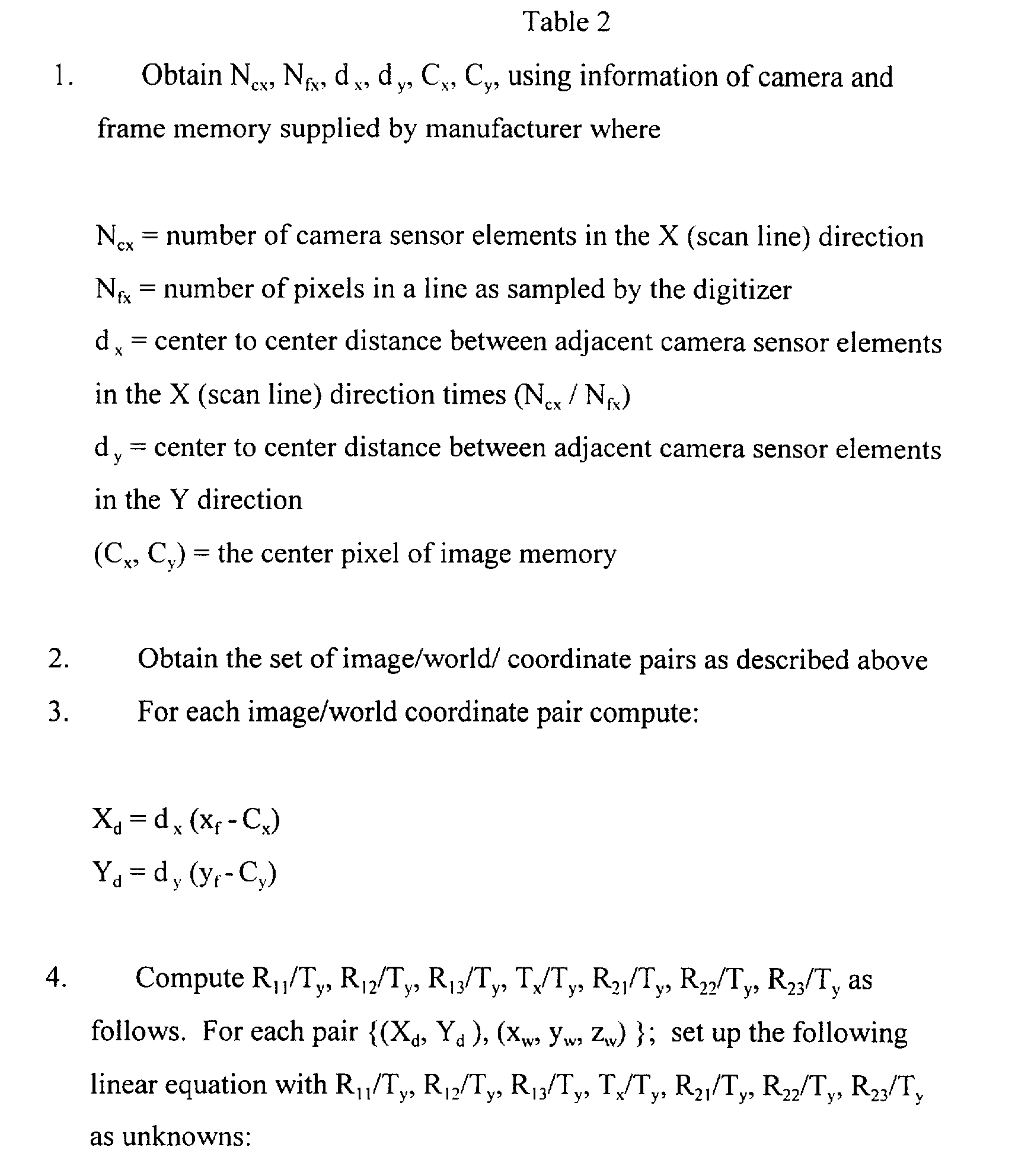


- xd = dx (xf-Cx)/sx
- yd = dy (yf-Cy)
- Dx = xdk(xd 2 + yd 2)
- Dy = ydk(xd 2 + yd 2).
However it is more efficient to solve the equation symbolically using (xu, yu) ahead of time to reduce the number of arithmetic operations during run time. After solving the equations symbolically, the following equations are obtained:
= π - radians
Discrepancies between the sensor values and the expected values may be assumed due to calibration error. The calibration may be refined by calculating the average discrepancy and modifying the calibration parameters accordingly.
Claims (27)
- Apparatus for determining a profile of an object, the apparatus comprising:at least one light source for providing a sheet of light directed at the object from at least two angles, the profile of the object being illuminated at the intersection of said sheet of light and the object;at least two optical detectors, collectively viewing the profile, each viewing a different portion of the profile than that viewed by the others, each of said optical detectors providing an output signal representative of its view of the profile ; andan image processor, operatively connected to said optical detectors and responsive to said output signals from said optical detectors to provide one or more profile signals collectively representing the profile.
- The apparatus of claim 1 wherein the image processor employs calibration parameters for interrelating said output signals from said optical detectors.
- The apparatus of claim 2 wherein said calibration parameters represent parameters derived by having said at least two optical detectors view a known target and having at least one of said at least two optical detectors view an intersection of said sheet of light and a target surface.
- The apparatus of claim 2 or 3 wherein the image processor is arranged to interrelate said output signals without using a feature of the content of the output signals.
- The apparatus of claim 1, 2, 3 or 4 wherein said sheet of light is generally planar in the vicinity of the object.
- The apparatus of any preceding claim wherein the object is an edge of an airfoil.
- The apparatus of any preceding claim wherein said at least two optical detectors comprises two video cameras, one of said video cameras positioned on one side of the object, the other of said video cameras positioned on the other side of said object.
- The apparatus of any preceding claim wherein the apparatus further comprises means for evaluating the profile.
- A method for determining a profile of an object, the method comprising the steps of:providing at least one light source for projecting a sheet of light directed at the object from at least two angles, the profile of the object being illuminated at the intersection of said sheet of light and the object;providing at least two optical detectors, collectively viewing the profile, each viewing a different portion of the profile than that viewed by the others, each of said optical detectors providing an output signal representative of its view of the profile; andproviding an image processor. operatively connected to said optical detectors and responsive to said output signals from said optical detectors to provide one or more profile signals collectively representing the profile.
- The method of claim 9 wherein the image processor employs calibration parameters for interrelating said output signals from said optical detectors.
- The method of claim 9 or 10 wherein the image processor interrelates said output signals without using a feature of the content of the output signals.
- The method of claim 9, 10 or 1 1 wherein the object is an edge of an airfoil.
- Apparatus for evaluating a profile of a blade edge in a system having a processor for such evaluation, the profile being represented by a plurality of data points in a coordinate system. the apparatus comprising:means for providing a profile tolerance band;means for aligning the profile and said profile tolerance band;means for providing a plurality of memory locations for storing values, each of said memory locations being associated with a point in the coordinate system;means for setting said value stored in each of said memory locations, where those not associated with points of said tolerance band are set to a first value, and those associated with points of said tolerance band are set to a second value;means for determining whether the points of the profile are within said tolerance band by evaluating said value of said memory locations which are associated with points of the profile.
- A method for evaluating a profile of a blade edge in a system having a processor for such evaluation, the profile being represented by a plurality of data points in a coordinate system, the method comprising the steps of:providing a profile tolerance band;aligning the profile and said profile tolerance band;providing a plurality of memory locations for storing values, each of said memory locations being associated with a point in the coordinate system;setting said value stored in each of said memory locations, where those not associated with points of said tolerance band are set to a first value, and those associated with points of said tolerance band are set to a second value;determining whether the points of the profile are within said tolerance band by evaluating said value of said memory locations which are associated with points of the profile.
- The method of claim 14 wherein said step of determining comprises evaluating said value of said memory locations which are associated with points of the profile, where if said value is equal to said second value then the profile is within said tolerance band, if said value is equal to said first value, then the profile is out of said tolerance band.
- The method of claim 14 wherein said step of setting comprises setting said value of all of said memory locations to said first value, and then revising said value of said memory locations that are associated with points of said tolerance hand to said second value.
- The method of claim 14 further comprising the step of changing the value stored in said memory locations associated with points of the profile, to a value that reflects the results of said step of evaluating, where said value is changed to one indicating that the profile is within tolerance, or a different one indicating that the profile is out of tolerance.
- The method of claim 14 wherein said memory locations are those of a video display and said values represent a color at a location on said display of said video display.
- The method of claim 14 wherein said plurality of memory locations comprises a first plurality of memory locations, the method further comprising the steps of:wherein said step of determining comprises performing a logical function on the values stored in a pair of said memory locations, one from each of said first and second plurality of memory locations, where said pair are each associated with the same point in said coordinate system.providing a second plurality of memory locations for storing values, each of said memory elements being associated with a point in a coordinate system;setting said value stored in each of said memory locations, where those not associated with points of said profile are set to a third value, and those associated with points of said profile band are set to a fourth value;
- The method of claim 19 wherein said first, second, third and fourth values comprise binary values.
- Apparatus for evaluating a profile of a blade edge in a system having a processor for such evaluation, the profile having a tip and two sides, one of the two sides being flatter than the other, the profile being represented by a plurality of data points in a coordinate system, the method comprising the steps of:means for rotating the profile to orient it such that one of the two sides is substantially parallel to a coordinate axis; andmeans for determining which point represents the tip by determining which point has an extrememost coordinate value in one direction along said coordinate axis.
- A method for evaluating a profile of a blade edge in a system having a processor for such evaluation, the profile having a tip and two sides, one of the two sides being flatter than the other, the profile being represented by a plurality of data points in a coordinate system, the method comprising the steps of:rotating the profile to orient it such that one of the two sides is substantially parallel to a coordinate axis; anddetermining which point represents the tip by determining which point has an extreme most coordinate value in one direction along said coordinate axis.
- The method of claim 22 wherein said step of rotating the profile comprises the steps of:locating a relatively flat section one of the two sides of the profile ;determining an equation of line representing the relatively flat section ; androtating the profile to orient it such that said line representing the relatively flat section is substantially parallel to a coordinate axis.
- The method of claim 23 wherein the one side of the profile is the flatter of the two sides of the profile.
- The method of claim 24 further comprising the step of determining the width of the profile at a distance from the tip.
- Apparatus for determining the width of a profile of a blade edge in a system having a processor for such evaluation, the profile having a tip and two sides, the profile being represented by a plurality of data points in a coordinate system, the method comprising the steps of:means for determining the tip of the profile;means for determining a median line;means for determining a point on the median line that is at a distance from the tip;means for determining a line perpendicular to said median line and including said determined point on said median line;means for determining two groups of points, one group for each side of the profile, proximate to where said perpendicular line intersects with the side of the profile ;means for determining two intersected lines, one to represent each of said two groups of points; andmeans for determine the length of said perpendicular line lying between said two intersected lines.
- A method for determining the width of a profile of a blade edge in a system having a processor for such evaluation, the profile having a tip and two sides, the profile being represented by a plurality of data points in a coordinate system, the method comprising the steps of:determining the tip of the profile ;determining a median line;determining a point on the median line that is at a distance from the tip ;determining a line perpendicular to said median line and including said determined point on said median line.determining two groups of points, one group for each side of the profile, proximate to where said perpendicular line intersects with the side of the profile;determining two intersected lines, one to represent each of said two groups of points; anddetermine the width as the length of said perpendicular line lying between said two intersected lines.
Applications Claiming Priority (2)
| Application Number | Priority Date | Filing Date | Title |
|---|---|---|---|
| US08/801,336 US6175415B1 (en) | 1997-02-19 | 1997-02-19 | Optical profile sensor |
| US801336 | 1997-02-19 |
Publications (3)
| Publication Number | Publication Date |
|---|---|
| EP0866308A2 true EP0866308A2 (en) | 1998-09-23 |
| EP0866308A3 EP0866308A3 (en) | 2000-01-05 |
| EP0866308B1 EP0866308B1 (en) | 2004-10-06 |
Family
ID=25180840
Family Applications (1)
| Application Number | Title | Priority Date | Filing Date |
|---|---|---|---|
| EP98301249A Expired - Lifetime EP0866308B1 (en) | 1997-02-19 | 1998-02-19 | Optical profile sensor |
Country Status (4)
| Country | Link |
|---|---|
| US (2) | US6175415B1 (en) |
| EP (1) | EP0866308B1 (en) |
| JP (1) | JPH10311711A (en) |
| DE (1) | DE69826753T2 (en) |
Cited By (10)
| Publication number | Priority date | Publication date | Assignee | Title |
|---|---|---|---|---|
| WO2001007868A1 (en) * | 1999-07-27 | 2001-02-01 | California Cedar Products Company | Automatic circular saw tooth inspection system and method |
| WO2001020255A1 (en) * | 1999-09-13 | 2001-03-22 | Siemens Aktiengesellschaft | Device for inspecting a three-dimensional surface structure |
| WO2001077615A1 (en) * | 2000-04-07 | 2001-10-18 | I-Ware Laboratory Co., Ltd. | Shape determining method and device |
| EP1351034A2 (en) * | 2002-04-01 | 2003-10-08 | General Electric Company | Method and apparatus for optical measurement of the leading edge position of an airfoil |
| EP1506371A1 (en) * | 2002-05-14 | 2005-02-16 | ROLLS-ROYCE plc | Method of generating an inspection program and method of generating a visual display |
| WO2008155269A2 (en) * | 2007-06-20 | 2008-12-24 | Gebr. Lennartz Gmbh & Co. Kg | Measuring arrangement and method for the optical measuring of separating tools |
| WO2009018894A1 (en) * | 2007-08-06 | 2009-02-12 | Carl Zeiss Industrielle Messtechnik Gmbh | Method and device for determining geometric data of a measured object |
| EP2562718A3 (en) * | 2011-08-26 | 2013-10-23 | General Electric Company | Inspection system and method for determining three dimensional model of an object |
| US11772223B2 (en) | 2019-05-17 | 2023-10-03 | Vitaly Tsukanov | Systems for blade sharpening and contactless blade sharpness detection |
| US11904428B2 (en) | 2019-10-25 | 2024-02-20 | Vitaly Tsukanov | Systems for blade sharpening and contactless blade sharpness detection |
Families Citing this family (52)
| Publication number | Priority date | Publication date | Assignee | Title |
|---|---|---|---|---|
| US7342665B2 (en) * | 1998-06-30 | 2008-03-11 | Drake Jr Thomas E | System and method for control of paint thickness |
| US6657733B1 (en) * | 1998-06-30 | 2003-12-02 | Lockheed Martin Corporation | Method and apparatus for detecting ultrasonic surface displacements using post-collection optical amplification |
| US6633384B1 (en) * | 1998-06-30 | 2003-10-14 | Lockheed Martin Corporation | Method and apparatus for ultrasonic laser testing |
| US7561281B2 (en) * | 1998-06-30 | 2009-07-14 | Lockheed Martin Corporation | System and method for controlling tube thickness |
| US7545509B2 (en) * | 1998-06-30 | 2009-06-09 | Lockheed Martin Corporation | System and method for online control of paper elasticity and thickness |
| US7612890B2 (en) * | 1998-06-30 | 2009-11-03 | Lockheed Martin Corporation | System and method for controlling wafer temperature |
| JP3961729B2 (en) | 1999-03-03 | 2007-08-22 | 株式会社デンソー | All-focus imaging device |
| US7286241B2 (en) * | 1999-06-24 | 2007-10-23 | Lockheed Martin Corporation | System and method for high-speed laser detection of ultrasound |
| GB0002421D0 (en) * | 2000-02-02 | 2000-03-22 | Rolls Royce Plc | A conformal gauge created using rapid prototyping |
| WO2002006848A2 (en) * | 2000-07-14 | 2002-01-24 | Lockheed Martin Corporation | System and method for locating and positioning an ultrasonic signal generator for testing purposes |
| US6868194B2 (en) * | 2001-12-19 | 2005-03-15 | General Electric Company | Method for the extraction of image features caused by structure light using image reconstruction |
| US7428061B2 (en) * | 2002-08-14 | 2008-09-23 | Metris Ipr N.V. | Optical probe for scanning the features of an object and methods thereof |
| US7009717B2 (en) * | 2002-08-14 | 2006-03-07 | Metris N.V. | Optical probe for scanning the features of an object and methods therefor |
| US7679757B1 (en) * | 2002-10-31 | 2010-03-16 | BYTEWISE Measurement Systems LLC. | Non-contact profile measurement system |
| ES2324658T3 (en) | 2002-12-31 | 2009-08-12 | D4D Technologies Llc. | LASER DIGITALIZING SYSTEM FOR DENTAL APPLICATIONS. |
| WO2004085956A2 (en) | 2003-03-24 | 2004-10-07 | D3D, L.P. | Laser digitizer system for dental applications |
| US20060192939A1 (en) * | 2003-04-16 | 2006-08-31 | Lebeau Robert C | Optical sharpness meter |
| DE10317778B4 (en) * | 2003-04-16 | 2017-08-31 | Cascade Microtech, Inc. | A method of increasing the accuracy of positioning a first object relative to a second object |
| US20040207857A1 (en) * | 2003-04-16 | 2004-10-21 | Lebeau Robert C. | Optical sharpness meter |
| WO2004100067A2 (en) * | 2003-04-30 | 2004-11-18 | D3D, L.P. | Intra-oral imaging system |
| JP4571625B2 (en) * | 2003-05-05 | 2010-10-27 | ディーフォーディー テクノロジーズ エルエルシー | Imaging by optical tomography |
| US20040263840A1 (en) * | 2003-06-25 | 2004-12-30 | Segall Stephen B. | Calibration of reconfigurable inspection machine |
| US6969821B2 (en) * | 2003-06-30 | 2005-11-29 | General Electric Company | Airfoil qualification system and method |
| US6997046B2 (en) * | 2003-08-01 | 2006-02-14 | General Electric Company | Method and apparatus for fixtured wax and trace |
| WO2005027770A2 (en) * | 2003-09-17 | 2005-03-31 | D4D Technologies, L.P. | High speed multiple line three-dimensional digitization |
| US7327857B2 (en) * | 2004-03-09 | 2008-02-05 | General Electric Company | Non-contact measurement method and apparatus |
| EP1615153A3 (en) * | 2004-07-09 | 2011-05-04 | Rolls-Royce Plc | Selection of component |
| US7511722B1 (en) * | 2004-08-27 | 2009-03-31 | Apple Inc. | Method and system for fast 90 degree rotation of arrays |
| TWI267035B (en) | 2004-09-27 | 2006-11-21 | Elan Microelectronics Corp | Optical sensing part and method for quickly inspecting its matching part |
| CN1316226C (en) * | 2005-01-04 | 2007-05-16 | 李小路 | Method for real-time measurement of airfoil deformation using dual laser |
| US7623250B2 (en) * | 2005-02-04 | 2009-11-24 | Stryker Leibinger Gmbh & Co. Kg. | Enhanced shape characterization device and method |
| GB0612925D0 (en) * | 2006-06-29 | 2006-08-09 | Rolls Royce Plc | Method and system for measuring a component |
| US20080117438A1 (en) * | 2006-11-16 | 2008-05-22 | Solvision Inc. | System and method for object inspection using relief determination |
| US20080134505A1 (en) * | 2006-12-12 | 2008-06-12 | Thomas Andrew Gabriel | Method and fixture for manufacturing components |
| DE102007009851B3 (en) * | 2007-02-28 | 2008-05-29 | Kuka Roboter Gmbh | Industrial robot's position determining method, involves determining position of robot relative to object based on assigned model points, and determining position of camera assigned to image and position of camera relative to robot |
| US7578178B2 (en) * | 2007-09-28 | 2009-08-25 | United Technologies Corporation | Method of inspecting turbine internal cooling features using non-contact scanners |
| US7869026B2 (en) * | 2007-12-21 | 2011-01-11 | United Technologies Corp. | Targeted artifacts and methods for evaluating 3-D coordinate system measurement accuracy of optical 3-D measuring systems using such targeted artifacts |
| US8883261B2 (en) | 2007-12-21 | 2014-11-11 | United Technologies Corporation | Artifacts, method of creating such artifacts and methods of using such artifacts |
| US8105651B2 (en) * | 2007-12-21 | 2012-01-31 | United Technologies Corp. | Artifacts, methods of creating such artifacts and methods of using such artifacts |
| US8184909B2 (en) | 2008-06-25 | 2012-05-22 | United Technologies Corporation | Method for comparing sectioned geometric data representations for selected objects |
| DE102009010355A1 (en) * | 2009-02-25 | 2010-09-02 | Solving 3D Gmbh | Profile logging device for logging surface profile of steel sheet coils, has stereo camera arrangements, where one of arrangements is arranged such that other arrangement detects surface areas of object |
| DE102010036762B4 (en) * | 2010-06-16 | 2017-12-28 | Wincor Nixdorf International Gmbh | Method and device for shape recognition of empties containers in reverse vending machines by means of a light-section triangulation method |
| JP5597056B2 (en) * | 2010-08-02 | 2014-10-01 | 株式会社キーエンス | Image measuring apparatus, image measuring method, and program for image measuring apparatus |
| JP4869430B1 (en) * | 2010-09-24 | 2012-02-08 | 任天堂株式会社 | Image processing program, image processing apparatus, image processing system, and image processing method |
| DE102010047137A1 (en) * | 2010-09-30 | 2012-04-05 | Kronoplus Technical Ag | Method for monitoring production of profile of e.g. flooring panel, involves redefining measurement of horizontal and vertical reference edges by displacing detection devices comprising laser sources and cameras |
| DE102011000304B4 (en) * | 2011-01-25 | 2016-08-04 | Data M Sheet Metal Solutions Gmbh | Calibration of laser light section sensors with simultaneous measurement |
| DE102011007520A1 (en) * | 2011-04-15 | 2012-10-18 | Krones Aktiengesellschaft | Method for calibrating orientation unit of labeling device for e.g. glass bottle for storing drinks, involves calculating algorithm for coordinate transformation from camera coordinate system into absolute Cartesian coordinate system |
| FR2981450B1 (en) * | 2011-10-17 | 2014-06-06 | Eads Europ Aeronautic Defence | SYSTEM AND METHOD FOR CONTROLLING THE QUALITY OF AN OBJECT |
| TR201811449T4 (en) * | 2012-11-07 | 2018-09-21 | Artec Europe S A R L | Method for observing linear dimensions of three-dimensional objects. |
| US20190255997A1 (en) * | 2018-02-19 | 2019-08-22 | Gentex Corporation | Imaging device for rearview assembly |
| JP2020003276A (en) * | 2018-06-27 | 2020-01-09 | リョーエイ株式会社 | Oil detector and method for detecting oil |
| US10845189B2 (en) | 2019-03-27 | 2020-11-24 | Raythoen Technologies Corporation | Calibration for laser inspection |
Citations (8)
| Publication number | Priority date | Publication date | Assignee | Title |
|---|---|---|---|---|
| US3837198A (en) * | 1973-04-16 | 1974-09-24 | Bendix Corp | Stereoscopic gage and gaging system |
| EP0126576A2 (en) * | 1983-05-19 | 1984-11-28 | Airfoil Textron Inc. | Airfoil inspection method |
| GB2149094A (en) * | 1983-11-01 | 1985-06-05 | Rolls Royce | Observing change in a shape of rotating blade |
| WO1991008439A1 (en) * | 1989-12-05 | 1991-06-13 | Böhler Gesellschaft M.B.H. | Process and arrangement for optoelectronic measurement of objects |
| US5028799A (en) * | 1988-08-01 | 1991-07-02 | Robotic Vision System, Inc. | Method and apparatus for three dimensional object surface determination using co-planar data from multiple sensors |
| US5162659A (en) * | 1991-03-06 | 1992-11-10 | Northwest Airlines, Inc. | Method and apparatus for noncontact inspection of engine blades |
| DE4429516A1 (en) * | 1993-08-20 | 1995-02-23 | Shima Seiki Mfg | Device and method for measuring the width of cutting blades |
| WO1996000159A1 (en) * | 1994-06-23 | 1996-01-04 | Groenskov Leif | Arrangement for measuring the quality of rails, in which a movable frame is connected to the bogie |
Family Cites Families (16)
| Publication number | Priority date | Publication date | Assignee | Title |
|---|---|---|---|---|
| US4226536A (en) * | 1979-02-23 | 1980-10-07 | Dreyfus Marc G | Electro-optical contour measuring system |
| DE3070433D1 (en) | 1980-12-18 | 1985-05-09 | Ibm | Method for the inspection and automatic sorting of objects with configurations of fixed dimensional tolerances, and device for carrying out the method |
| CH646516A5 (en) | 1982-02-25 | 1984-11-30 | Speno International | METHOD AND DEVICE FOR MEASURING THE CROSS-SECTION PROFILE OF A MUSHROOM OF A RAIL OF A RAILWAY. |
| US4563095A (en) | 1982-12-20 | 1986-01-07 | Essex Group, Inc. | Method and apparatus for monitoring the surface of elongated objects |
| GB8508391D0 (en) | 1985-03-30 | 1985-05-09 | Ae Plc | Measurement of engineering components |
| GB2175396B (en) | 1985-05-22 | 1989-06-28 | Filler Protection Developments | Apparatus for examining objects |
| US4827436A (en) | 1987-04-22 | 1989-05-02 | Micro Component Technology, Inc. | Non-contact high resolution displacement measurement technique |
| US4875777A (en) * | 1987-09-30 | 1989-10-24 | Industrial Technology Institute | Off-axis high accuracy structured light profiler |
| US5090811A (en) | 1989-05-31 | 1992-02-25 | General Electric Company | Optical radius gauge |
| US5325443A (en) | 1990-07-06 | 1994-06-28 | Westinghouse Electric Corporation | Vision system for inspecting a part having a substantially flat reflective surface |
| US5619587A (en) * | 1991-05-10 | 1997-04-08 | Aluminum Company Of America | System and method for contactlessly gauging the thickness of a contoured object, such as a vehicle wheel |
| NO174025C (en) * | 1991-10-11 | 1994-03-02 | Metronor Sa | System for spot measurement of spatial coordinates |
| US5444536A (en) | 1992-04-28 | 1995-08-22 | Mtu Motoren- Und Turbinen-Union Muenchen Gmbh | Apparatus for measuring the curvature of a profile, such as an edge of a turbine blade |
| US5500737A (en) | 1993-07-21 | 1996-03-19 | General Electric Company | Method for measuring the contour of a surface |
| US5552822A (en) | 1993-11-12 | 1996-09-03 | Nallakrishnan; Ravi | Apparatus and method for setting depth of cut of micrometer surgical knife |
| US5517310A (en) * | 1994-06-30 | 1996-05-14 | Solar Turbines Incorporated | Method and apparatus for obtaining and analyzing an image of a elongate slot |
-
1997
- 1997-02-19 US US08/801,336 patent/US6175415B1/en not_active Expired - Lifetime
- 1997-11-18 US US08/972,273 patent/US6205240B1/en not_active Expired - Lifetime
-
1998
- 1998-02-19 DE DE69826753T patent/DE69826753T2/en not_active Expired - Lifetime
- 1998-02-19 JP JP10036503A patent/JPH10311711A/en active Pending
- 1998-02-19 EP EP98301249A patent/EP0866308B1/en not_active Expired - Lifetime
Patent Citations (8)
| Publication number | Priority date | Publication date | Assignee | Title |
|---|---|---|---|---|
| US3837198A (en) * | 1973-04-16 | 1974-09-24 | Bendix Corp | Stereoscopic gage and gaging system |
| EP0126576A2 (en) * | 1983-05-19 | 1984-11-28 | Airfoil Textron Inc. | Airfoil inspection method |
| GB2149094A (en) * | 1983-11-01 | 1985-06-05 | Rolls Royce | Observing change in a shape of rotating blade |
| US5028799A (en) * | 1988-08-01 | 1991-07-02 | Robotic Vision System, Inc. | Method and apparatus for three dimensional object surface determination using co-planar data from multiple sensors |
| WO1991008439A1 (en) * | 1989-12-05 | 1991-06-13 | Böhler Gesellschaft M.B.H. | Process and arrangement for optoelectronic measurement of objects |
| US5162659A (en) * | 1991-03-06 | 1992-11-10 | Northwest Airlines, Inc. | Method and apparatus for noncontact inspection of engine blades |
| DE4429516A1 (en) * | 1993-08-20 | 1995-02-23 | Shima Seiki Mfg | Device and method for measuring the width of cutting blades |
| WO1996000159A1 (en) * | 1994-06-23 | 1996-01-04 | Groenskov Leif | Arrangement for measuring the quality of rails, in which a movable frame is connected to the bogie |
Cited By (15)
| Publication number | Priority date | Publication date | Assignee | Title |
|---|---|---|---|---|
| US6462811B1 (en) | 1999-07-27 | 2002-10-08 | California Cedar Products Company | Automatic circular saw tooth inspection system and method |
| WO2001007868A1 (en) * | 1999-07-27 | 2001-02-01 | California Cedar Products Company | Automatic circular saw tooth inspection system and method |
| US6710867B2 (en) | 1999-09-13 | 2004-03-23 | Siemens Aktiengesellschaft | Device and method for inspecting a three-dimensional surface structure |
| WO2001020255A1 (en) * | 1999-09-13 | 2001-03-22 | Siemens Aktiengesellschaft | Device for inspecting a three-dimensional surface structure |
| WO2001077615A1 (en) * | 2000-04-07 | 2001-10-18 | I-Ware Laboratory Co., Ltd. | Shape determining method and device |
| EP1351034A2 (en) * | 2002-04-01 | 2003-10-08 | General Electric Company | Method and apparatus for optical measurement of the leading edge position of an airfoil |
| EP1351034A3 (en) * | 2002-04-01 | 2003-11-26 | General Electric Company | Method and apparatus for optical measurement of the leading edge position of an airfoil |
| EP1506371A1 (en) * | 2002-05-14 | 2005-02-16 | ROLLS-ROYCE plc | Method of generating an inspection program and method of generating a visual display |
| EP2343500A1 (en) * | 2002-05-14 | 2011-07-13 | Rolls-Royce plc | Method of generating an inspection program and method of generating a visual display |
| WO2008155269A2 (en) * | 2007-06-20 | 2008-12-24 | Gebr. Lennartz Gmbh & Co. Kg | Measuring arrangement and method for the optical measuring of separating tools |
| WO2008155269A3 (en) * | 2007-06-20 | 2009-06-04 | Lennartz Gmbh & Co Kg Geb | Measuring arrangement and method for the optical measuring of separating tools |
| WO2009018894A1 (en) * | 2007-08-06 | 2009-02-12 | Carl Zeiss Industrielle Messtechnik Gmbh | Method and device for determining geometric data of a measured object |
| EP2562718A3 (en) * | 2011-08-26 | 2013-10-23 | General Electric Company | Inspection system and method for determining three dimensional model of an object |
| US11772223B2 (en) | 2019-05-17 | 2023-10-03 | Vitaly Tsukanov | Systems for blade sharpening and contactless blade sharpness detection |
| US11904428B2 (en) | 2019-10-25 | 2024-02-20 | Vitaly Tsukanov | Systems for blade sharpening and contactless blade sharpness detection |
Also Published As
| Publication number | Publication date |
|---|---|
| DE69826753T2 (en) | 2006-03-02 |
| JPH10311711A (en) | 1998-11-24 |
| US6175415B1 (en) | 2001-01-16 |
| EP0866308A3 (en) | 2000-01-05 |
| EP0866308B1 (en) | 2004-10-06 |
| DE69826753D1 (en) | 2004-11-11 |
| US6205240B1 (en) | 2001-03-20 |
Similar Documents
| Publication | Publication Date | Title |
|---|---|---|
| EP0866308B1 (en) | Optical profile sensor | |
| EP2183544B1 (en) | Non-contact measurement apparatus and method | |
| US10812694B2 (en) | Real-time inspection guidance of triangulation scanner | |
| Lindner et al. | Lateral and depth calibration of PMD-distance sensors | |
| US20150015701A1 (en) | Triangulation scanner having motorized elements | |
| JP2005321278A (en) | Three dimensional shape input apparatus | |
| US5090811A (en) | Optical radius gauge | |
| EP3719441A1 (en) | Three-dimensional measuring system | |
| JP2011521231A (en) | Accurate image acquisition on structured light systems for optical measurement of shape and position | |
| JP7353757B2 (en) | Methods for measuring artifacts | |
| Dekiff et al. | Three-dimensional data acquisition by digital correlation of projected speckle patterns | |
| Strobl et al. | The DLR multisensory hand-guided device: The laser stripe profiler | |
| Trucco et al. | Acquisition of consistent range data using local calibration | |
| EP3989169A1 (en) | Hybrid photogrammetry | |
| Tai et al. | Noncontact profilometric measurement of large-form parts | |
| Trucco et al. | Direct calibration and data consistency in 3-D laser scanning | |
| Clark et al. | Measuring range using a triangulation sensor with variable geometry | |
| Sansoni et al. | A three-dimensional imaging system for industrial applications with improved flexibility and robustness | |
| Harding | Latest optical methods for industrial dimensional metrology | |
| Jovanović et al. | Accuracy assessment of structured-light based industrial optical scanner | |
| Sun et al. | A Complete Calibration Method for a Line Structured Light Vision System. | |
| Sun et al. | A 3D acquisition system combination of structured-light scanning and shape from silhouette | |
| Blais et al. | ShapeGrabber FootScanner: a low cost high accuracy 3D system for the acquisition of human feet | |
| Christoph et al. | Coordinate Metrology | |
| Huicheng et al. | Datacloud fusion in three-dimensional laser comparator |
Legal Events
| Date | Code | Title | Description |
|---|---|---|---|
| PUAI | Public reference made under article 153(3) epc to a published international application that has entered the european phase |
Free format text: ORIGINAL CODE: 0009012 |
|
| AK | Designated contracting states |
Kind code of ref document: A2 Designated state(s): DE FR GB |
|
| AX | Request for extension of the european patent |
Free format text: AL;LT;LV;MK;RO;SI |
|
| RIC1 | Information provided on ipc code assigned before grant |
Free format text: 6G 01B 11/24 A, 6G 01B 11/02 B |
|
| PUAL | Search report despatched |
Free format text: ORIGINAL CODE: 0009013 |
|
| AK | Designated contracting states |
Kind code of ref document: A3 Designated state(s): AT BE CH DE DK ES FI FR GB GR IE IT LI LU MC NL PT SE |
|
| AX | Request for extension of the european patent |
Free format text: AL;LT;LV;MK;RO;SI |
|
| 17P | Request for examination filed |
Effective date: 20000221 |
|
| AKX | Designation fees paid |
Free format text: DE FR GB |
|
| 17Q | First examination report despatched |
Effective date: 20030711 |
|
| GRAP | Despatch of communication of intention to grant a patent |
Free format text: ORIGINAL CODE: EPIDOSNIGR1 |
|
| GRAS | Grant fee paid |
Free format text: ORIGINAL CODE: EPIDOSNIGR3 |
|
| GRAA | (expected) grant |
Free format text: ORIGINAL CODE: 0009210 |
|
| AK | Designated contracting states |
Kind code of ref document: B1 Designated state(s): DE FR GB |
|
| REG | Reference to a national code |
Ref country code: GB Ref legal event code: FG4D |
|
| REF | Corresponds to: |
Ref document number: 69826753 Country of ref document: DE Date of ref document: 20041111 Kind code of ref document: P |
|
| ET | Fr: translation filed | ||
| PLBE | No opposition filed within time limit |
Free format text: ORIGINAL CODE: 0009261 |
|
| STAA | Information on the status of an ep patent application or granted ep patent |
Free format text: STATUS: NO OPPOSITION FILED WITHIN TIME LIMIT |
|
| 26N | No opposition filed |
Effective date: 20050707 |
|
| PGFP | Annual fee paid to national office [announced via postgrant information from national office to epo] |
Ref country code: FR Payment date: 20100223 Year of fee payment: 13 |
|
| REG | Reference to a national code |
Ref country code: FR Ref legal event code: ST Effective date: 20111102 |
|
| PG25 | Lapsed in a contracting state [announced via postgrant information from national office to epo] |
Ref country code: FR Free format text: LAPSE BECAUSE OF NON-PAYMENT OF DUE FEES Effective date: 20110228 |
|
| PGFP | Annual fee paid to national office [announced via postgrant information from national office to epo] |
Ref country code: DE Payment date: 20130213 Year of fee payment: 16 Ref country code: GB Payment date: 20130213 Year of fee payment: 16 |
|
| REG | Reference to a national code |
Ref country code: DE Ref legal event code: R119 Ref document number: 69826753 Country of ref document: DE |
|
| GBPC | Gb: european patent ceased through non-payment of renewal fee |
Effective date: 20140219 |
|
| REG | Reference to a national code |
Ref country code: DE Ref legal event code: R119 Ref document number: 69826753 Country of ref document: DE Effective date: 20140902 |
|
| PG25 | Lapsed in a contracting state [announced via postgrant information from national office to epo] |
Ref country code: DE Free format text: LAPSE BECAUSE OF NON-PAYMENT OF DUE FEES Effective date: 20140902 Ref country code: GB Free format text: LAPSE BECAUSE OF NON-PAYMENT OF DUE FEES Effective date: 20140219 |