EP0866210A2 - Method for operating a tool and apparatus for transmission of rotary torque and speed of rotation of a drive unit to that tool - Google Patents
Method for operating a tool and apparatus for transmission of rotary torque and speed of rotation of a drive unit to that tool Download PDFInfo
- Publication number
- EP0866210A2 EP0866210A2 EP98104400A EP98104400A EP0866210A2 EP 0866210 A2 EP0866210 A2 EP 0866210A2 EP 98104400 A EP98104400 A EP 98104400A EP 98104400 A EP98104400 A EP 98104400A EP 0866210 A2 EP0866210 A2 EP 0866210A2
- Authority
- EP
- European Patent Office
- Prior art keywords
- hydraulic
- gripper
- torque
- head
- speed
- Prior art date
- Legal status (The legal status is an assumption and is not a legal conclusion. Google has not performed a legal analysis and makes no representation as to the accuracy of the status listed.)
- Granted
Links
- 230000005540 biological transmission Effects 0.000 title claims abstract description 7
- 238000000034 method Methods 0.000 title claims description 10
- 239000012530 fluid Substances 0.000 claims description 12
- BTCSSZJGUNDROE-UHFFFAOYSA-N gamma-aminobutyric acid Chemical compound NCCCC(O)=O BTCSSZJGUNDROE-UHFFFAOYSA-N 0.000 claims description 3
- 230000007246 mechanism Effects 0.000 claims description 2
- 230000004075 alteration Effects 0.000 abstract 1
- 238000005553 drilling Methods 0.000 description 4
- 239000011435 rock Substances 0.000 description 2
- 230000008878 coupling Effects 0.000 description 1
- 238000010168 coupling process Methods 0.000 description 1
- 238000005859 coupling reaction Methods 0.000 description 1
Images

Classifications
-
- B—PERFORMING OPERATIONS; TRANSPORTING
- B66—HOISTING; LIFTING; HAULING
- B66C—CRANES; LOAD-ENGAGING ELEMENTS OR DEVICES FOR CRANES, CAPSTANS, WINCHES, OR TACKLES
- B66C3/00—Load-engaging elements or devices attached to lifting or lowering gear of cranes or adapted for connection therewith and intended primarily for transmitting lifting forces to loose materials; Grabs
-
- E—FIXED CONSTRUCTIONS
- E21—EARTH DRILLING; MINING
- E21B—EARTH DRILLING, e.g. DEEP DRILLING; OBTAINING OIL, GAS, WATER, SOLUBLE OR MELTABLE MATERIALS OR A SLURRY OF MINERALS FROM WELLS
- E21B11/00—Other drilling tools
- E21B11/04—Boring grabs
-
- E—FIXED CONSTRUCTIONS
- E21—EARTH DRILLING; MINING
- E21B—EARTH DRILLING, e.g. DEEP DRILLING; OBTAINING OIL, GAS, WATER, SOLUBLE OR MELTABLE MATERIALS OR A SLURRY OF MINERALS FROM WELLS
- E21B31/00—Fishing for or freeing objects in boreholes or wells
- E21B31/12—Grappling tools, e.g. tongs or grabs
-
- E—FIXED CONSTRUCTIONS
- E21—EARTH DRILLING; MINING
- E21B—EARTH DRILLING, e.g. DEEP DRILLING; OBTAINING OIL, GAS, WATER, SOLUBLE OR MELTABLE MATERIALS OR A SLURRY OF MINERALS FROM WELLS
- E21B4/00—Drives for drilling, used in the borehole
Definitions
- the invention relates to a method for operating a Work module, in particular a hydraulic gripper, which when drilling a borehole with a power turret and a drill pipe to remove obstacles, for example of rock, boulders etc. becomes.
- a gripper tool for example a hydraulic gripper, which with an additional device for the gripper tool is operated.
- the additional device must be provided at the borehole will.
- the invention has for its object to provide a method for operating a work module, such as a hydraulic gripper, and a device which make drilling and removing obstacles in a borehole extremely efficient in terms of equipment and in terms of time and costs.
- a work module such as a hydraulic gripper
- the task is procedurally characterized by the features of the claim 1 and device-wise by the features of the claim 6 solved.
- An essential basic idea of the invention is to use a tool that is designed in this way is that mechanical quantities, namely torque M and speed n, for example a turret with drill pipe, optionally and for a definable period of time in converts hydraulic power.
- any hydraulically actuated module can be used as the work module Unit or device or tool can be used.
- Method and device is the transfer of Torque and speed of a rotary head with a Kelly rod viewed in a hydraulic gripper as a work module. Speed and torque of the Kelly bar are with an additional work tool on the hydraulic gripper transfer.
- the work equipment is designed in this way and arranged between the drill pipe and hydraulic gripper, that speed and torque by changing the direction of rotation is converted into hydraulic power. This hydraulic Performance is at least the hydraulic gripper to exercise another function.
- the supply of the locking cylinders of the hydraulic gripper is essential with hydraulic fluid using a Hydraulic pump driven by the drill pipe becomes.
- the hydraulic head which is connected to the drill pipe, the rotary movements the drill pipe onto the work module, e.g. on the Hydraulic gripper, transmits.
- the open gripper blades can be placed on the bottom of the borehole be turned into the ground.
- the hydraulic head has Gearbox on which the speed of the drill string around increases a factor i and at the same time the torque of the Drill pipe reduced by the same factor.
- a freewheel is arranged for the transmission and the hydraulic pump, which is a speed transfer into the hydraulic pump allows in a first direction of rotation, but in the opposite direction of rotation locks.
- Grab blades in a direction of rotation of the drill pipe be turned into the ground.
- the hydraulic pump is driven in the direction of rotation and hydraulic cylinder of the work module actuated, in which Hydraulic fluid from the hydraulic pump into the hydraulic cylinder is promoted.
- a directional valve is provided to open the gripper blades, which has a toggle function to reverse the Hydraulic fluid flow is assigned.
- the work module or the hydraulic gripper with rock etc. is filled, it is attached to the drill pipe promoted the surface. It is advantageous if the hydraulic gripper pulled against a stop on the power turret can be. This is due to the tractive forces exerted Directional control valve switched accordingly and the rotary movement of the Drill pipe in hydraulic energy to open the grab buckets transformed.
- the working means according to the invention between an aggregate, whose torque and speed is transmitted, for example a power turret, and a work module, for example a drilling gripper module, is for hydraulic consumers in the broadest sense.
- a work module for example a drilling gripper module
- Gripper module or hydraulic gripper can also be hydraulic driven pumps, hammer mechanisms or motors via a rotary drive with circumferential and contact pressure and moved hydraulically by changing the direction of rotation, be pivoted, for example.
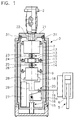
- Fig. 1 shows a hydraulic head 3, which as a working medium hydraulic power from over a drill pipe 2 mechanical quantities led to a borehole bottom, the Torque M and the speed n of the drill string 2, generated.
- the drill pipe 2 is non-rotatable with a power turret (not shown), which represents an aggregate 2, its torque M and speed n transferred and in hydraulic Power to be converted, connected.
- the hydraulic head 3 has a rotationally fixed with a coupling piece of the drill pipe 2 connected head cover 21st on which there is a head housing via a bearing unit 31 17 connects. With the rotating head housing 17 are connected a gear 7, a freewheel 11 and one Hydraulic pump 9, which are surrounded by the head housing 17.
- a switch housing 15, which has a switching element on the bottom, e.g. a spring-biased switch cam 16 and surrounds the head housing 17 to which it is connected in a rotationally fixed manner is via a work module 5 (see FIGS. 4 and 5), which stands on a borehole bottom (not shown), held non-rotatably.
- the transmission 7 which for example can be designed as a planetary gear, and having a gear ratio i reduces the input torque M by 1 / i times and increases the input speed n by the same factor i.
- the transmission output shaft 23 drives via a clutch 13 a drive shaft 24 of the freewheel 11, which at the first Direction of rotation torque M and speed n unaffected via a clutch 14 to a drive shaft of the hydraulic pump 9 passes on.
- the hydraulic pump 9 sucks out a hydraulic fluid a tank 27 and transmits speed and torque in volume flow and pressure.
- the hydraulic fluid is on the High-pressure side of the hydraulic pump 9 via a hydraulic line 18 to a valve 20, for example a 4/2-way valve to the hydraulic consumer, in this case to hydraulic cylinders 6 of the hydraulic gripper 5 (see FIG. 4 and 5) directed.
- a hydraulic return line 19 and the directional control valve 20 is guided back into the tank 27.
- a second and opposite direction of rotation Direction of rotation of the drill pipe 2 can rotate on the work module 5 are transmitted when the freewheel 11 in the second direction of rotation is blocked, i.e. a freewheel inner part 12 and one rigidly connected to the head housing 17 Freewheel outer ring 10 are coupled together.
- An output shaft 25 of the freewheel 11 can with respect to the Head housing 17 no longer exercise relative rotation, whereby the transmission output shaft 23 with 1 / i-fold drill pipe torque is held. Speed and torque transmitted to the head housing 17 via the gear housing 7, which is rotatably connected to the switch housing 15 is.
- the work module 5 firmly connected to the switch housing 15 is now with the torque and speed of the drill string 2 driven so that in this second direction of rotation the open gripper blades 4 (see FIGS. 4 and 5) in the bottom of a borehole can be rotated.
- Switch housing 15 with spring-loaded switching cam 16 offers the possibility of two different flow directions to realize the hydraulic fluid without the work module, for example a hydraulic gripper, and the hydraulic head 3 from a borehole for switching purposes must be transported out.
- the two different ones Directions of hydraulic fluid are reached when an additional load on the Hydraulic head 3 can be abandoned.
- the switch housing 15 is provided with a spring device 16 and enables Relative movements to the drill pipe 2, which for Circuit of the directional valve 20 can be used.
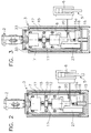
- the Switching of the directional valve 20 as a function of a load is apparent from Fig. 2. In this position the hydraulic gripper 5 (not shown) on the The bottom of the borehole and the drill pipe 2 will be loaded the switch housing 15 is exerted, whereby the directional control valve 20 switched and the direction of flow of the hydraulic fluid is turned over.
- Fig. 3 shows a further switching state.
- tensile forces act on the switch housing 15, which compared to the state of FIGS. 1 and 2 up to a cover-side stop 33 towards the bottom of the borehole is adjusted.
- This adjustment comes from the spring device 16 out.
- Hydraulic actuation of the hydraulic cylinders 6, of which only one cylinder is shown is done when the switch housing 15 and with this the work module 5 against a stop, for example pulling the turret (not shown), so that with simultaneous rotation of the drill pipe in Direction of rotation 2 the gripper blades 4 opened hydraulically will.
- a particularly simple variant of the Hydraulic head without switching housing 16 may be formed. It is then only a direction of flow of the hydraulic fluid possible. A second possibility would then exist therein, the work module 5 outside the borehole, for example by manual adjustment.
- FIGS. 1 to 3 show a preferred embodiment Device for transmitting the rotational energy of a Power rotary head using drill pipe 2 in a hydraulic gripper 5. Training and arrangement of the hydraulic head 3 corresponds to FIGS. 1 to 3. The same features were with provided identical reference numerals.
- Fig. 5 shows a second variant of an inventive Device with drilling gripper module 5, 3.
- the hydraulic head 3 is only shown in outline. Below the hydraulic head 3 are the hydraulic cylinders 6 in axial extension arranged.
- the hydraulic gripper 5 with its gripper blades 4 is also shown in the open position. 5 illustrates the non-rotatable arrangement of the hydraulic gripper 5 on the hydraulic head 3.
Abstract
Description
Die Erfindung betrifft ein Verfahren zum Betreiben eines Arbeitsmoduls, insbesondere eines Hydraulikgreifers, welcher beim Abbohren eines Bohrloches mit einem Kraftdrehkopf und einem Bohrgestänge zur Beseitigung von Hindernissen, beispielsweise von Felsgestein, Findlingen etc., eingesetzt wird.The invention relates to a method for operating a Work module, in particular a hydraulic gripper, which when drilling a borehole with a power turret and a drill pipe to remove obstacles, for example of rock, boulders etc. becomes.
Bisher ist es üblich, beim Auftreffen des Bohrgestänges auf ein Hindernis ein Spezialgerät einzusetzen, durch welches das Hindernis entfernt wird. In der Regel wird ein Greiferwerkzeug, beispielsweise ein Hydraulikgreifer, eingesetzt, welches mit einem zusätzlichen Gerät zum Greiferwerkzeug betrieben wird.So far it has been common to hit the drill pipe on an obstacle to using a special device through which the obstacle is removed. Usually a gripper tool, for example a hydraulic gripper, which with an additional device for the gripper tool is operated.
Das zusätzliche Gerät muß am Bohrloch bereitgestellt werden.The additional device must be provided at the borehole will.
Der Erfindung liegt die Aufgabe zugrunde, ein Verfahren zum Betreiben eines Arbeitsmoduls, beispielsweise eines Hydraulikgreifers, und eine Vorrichtung zu schaffen, welche ein Abbohren und das Beseitigen von Hindernissen in einem Bohrloch in gerätetechnischer Hinsicht und bezogen auf den Zeit- und Kostenaufwand außerordentlich effizient gestalten. The invention has for its object to provide a method for operating a work module, such as a hydraulic gripper, and a device which make drilling and removing obstacles in a borehole extremely efficient in terms of equipment and in terms of time and costs.
Verfahrensmäßig wird die Aufgabe durch die Merkmale des Anspruchs
1 und vorrichtungsmäßig durch die Merkmale des Anspruchs
6 gelöst.The task is procedurally characterized by the features of the claim
1 and device-wise by the features of the
Vorteilhafte und zweckmäßige Ausgestaltungen sind in den Unteransprüchen sowie in der Figurenbeschreibung enthalten.Advantageous and expedient configurations are in the Subclaims and included in the description of the figures.
Ein wesentlicher Grundgedanke der Erfindung besteht darin, ein Arbeitsmittel einzusetzen, welches derart ausgebildet ist, daß mechanische Größen, nämlich Drehmoment M und Drehzahl n, beispielsweise eines Kraftdrehkopfes mit Bohrgestänge, wahlweise und für eine vorgebbare Zeitdauer in hydraulische Leistung umwandelt. Die hydraulische Leistung wird auf ein Arbeitsmodul, beispielsweise auf einen Hydraulikgreifer, mit Hilfe einer Hydraulikleitung übertragen, wozu das Arbeitsmodul mit dem Arbeitsmittel verbunden wird.An essential basic idea of the invention is to use a tool that is designed in this way is that mechanical quantities, namely torque M and speed n, for example a turret with drill pipe, optionally and for a definable period of time in converts hydraulic power. The hydraulic performance a work module, for example a hydraulic gripper, transmitted using a hydraulic line, what the work module is connected to the work equipment.
Grundsätzlich kann als Arbeitsmodul jedes hydraulisch betätigbare Aggregat oder Gerät bzw. Werkzeug eingesetzt werden. Als bevorzugtes Anwendungsgebiet des erfindungsgemäßen Verfahrens und der Vorrichtung wird die Übertragung von Drehmoment und Drehzahl eines Kraftdrehkopfes mit einer Kellystange in einen Hydraulikgreifer als Arbeitsmodul betrachtet. Drehzahl und Drehmoment der Kellystange werden über ein zusätzliches Arbeitsmittel auf den Hydraulikgreifer übertragen. Das Arbeitsmittel ist derart ausgebildet und zwischen Bohrgestänge und Hydraulikgreifer angeordnet, daß Drehzahl und Drehmoment durch Änderung der Drehrichtung in hydraulische Leistung umgewandelt wird. Diese hydraulische Leistung wird dem Hydraulikgreifer zur Ausübung wenigstens einer weiteren Funktion zugeführt.Basically, any hydraulically actuated module can be used as the work module Unit or device or tool can be used. As a preferred application of the invention Method and device is the transfer of Torque and speed of a rotary head with a Kelly rod viewed in a hydraulic gripper as a work module. Speed and torque of the Kelly bar are with an additional work tool on the hydraulic gripper transfer. The work equipment is designed in this way and arranged between the drill pipe and hydraulic gripper, that speed and torque by changing the direction of rotation is converted into hydraulic power. This hydraulic Performance is at least the hydraulic gripper to exercise another function.
Wesentlich ist die Versorgung der Schließzylinder des Hydraulikgreifers mit Hydraulikflüssigkeit mit Hilfe einer Hydraulikpumpe, welche von dem Bohrgestänge angetrieben wird. Gleichzeitig ist vorgesehen, daß der Hydraulikkopf, welcher mit dem Bohrgestänge verbunden ist, die Drehbewegungen des Bohrgestänges auf das Arbeitsmodul, z.B. auf den Hydraulikgreifer, überträgt. Nach dem Absenken des Greifers auf die Bohrlochsohle können die geöffneten Greiferschaufeln in den Boden gedreht werden.The supply of the locking cylinders of the hydraulic gripper is essential with hydraulic fluid using a Hydraulic pump driven by the drill pipe becomes. At the same time, it is provided that the hydraulic head, which is connected to the drill pipe, the rotary movements the drill pipe onto the work module, e.g. on the Hydraulic gripper, transmits. After lowering the gripper The open gripper blades can be placed on the bottom of the borehole be turned into the ground.
In einer bevorzugten Ausbildung weist der Hydraulikkopf ein Getriebe auf, welches die Drehzahl des Bohrgestänges um einen Faktor i erhöht und gleichzeitig das Drehmoment des Bohrgestänges um den gleichen Faktor reduziert. Zwischen dem Getriebe und der Hydraulikpumpe ist ein Freilauf angeordnet, welcher eine Drehzahlübertragung in die Hydraulikpumpe in einer ersten Drehrichtung zuläßt, jedoch in der entgegengesetzten Drehrichtung sperrt. Nach dem Absenken des Hydraulikgreifers auf die Bohrlochsohle können die geöffneten Greiferschaufeln in einer Drehrichtung des Bohrgestänges in den Boden gedreht werden. In der entgegengesetzten Drehrichtung wird die Hydraulikpumpe angetrieben und Hydraulikzylinder des Arbeitsmoduls betätigt, in denen Hydraulikflüssigkeit von der Hydraulikpumpe in die Hydraulikzylinder gefördert wird.In a preferred embodiment, the hydraulic head has Gearbox on which the speed of the drill string around increases a factor i and at the same time the torque of the Drill pipe reduced by the same factor. Between a freewheel is arranged for the transmission and the hydraulic pump, which is a speed transfer into the hydraulic pump allows in a first direction of rotation, but in the opposite direction of rotation locks. After lowering of the hydraulic gripper on the bottom of the borehole can be opened Grab blades in a direction of rotation of the drill pipe be turned into the ground. In the opposite The hydraulic pump is driven in the direction of rotation and hydraulic cylinder of the work module actuated, in which Hydraulic fluid from the hydraulic pump into the hydraulic cylinder is promoted.
Zur Öffnung der Greiferschaufeln ist ein Wegeventil vorgesehen, welchem eine Umschaltfunktion zur Umkehrung des Hydraulikflüssigkeitsstroms zugeordnet ist.A directional valve is provided to open the gripper blades, which has a toggle function to reverse the Hydraulic fluid flow is assigned.
Zweckmäßigerweise werden Zug- und Druckkräfte, welche von dem Bohrgestänge auf den Hydraulikgreifer ausgeübt werden, zum Umschalten des Wegeventils genutzt. In einer vorteilhaften Ausbildung ist eine federvorgespannte Schaltnocke an einem Schaltgehäuse vorgesehen, über welches eine axiale Verschiebung zwischen Bohrgestänge und Arbeitsmodul erfolgt. Expedient tensile and compressive forces, which of the drill pipe is exerted on the hydraulic gripper, used to switch the directional valve. In an advantageous Training is based on a spring-loaded cam a switch housing is provided, via which an axial There is a shift between the drill pipe and the work module.
Wenn das Arbeitsmodul bzw. der Hydraulikgreifer mit Felsgestein u.ä. gefüllt ist, wird er über das Bohrgestänge an die Oberfläche befördert. Es ist vorteilhaft, wenn der Hydraulikgreifer gegen einen Anschlag am Kraftdrehkopf gezogen werden kann. Durch die ausgeübten Zugkräfte wird das Wegeventil entsprechend geschaltet und die Drehbewegung des Bohrgestänges in hydraulische Energie zum Öffnen der Greiferschaufeln umgewandelt.If the work module or the hydraulic gripper with rock etc. is filled, it is attached to the drill pipe promoted the surface. It is advantageous if the hydraulic gripper pulled against a stop on the power turret can be. This is due to the tractive forces exerted Directional control valve switched accordingly and the rotary movement of the Drill pipe in hydraulic energy to open the grab buckets transformed.
Das erfindungsgemäße Arbeitsmittel zwischen einem Aggregat, dessen Drehmoment und Drehzahl übertragen wird, beispielsweise einen Kraftdrehkopf, und einem Arbeitsmodul, beispielsweise einem Bohrgreifermodul, ist für Hydraulikverbraucher im weitesten Sinne einzusetzen. Neben dem bevorzugten Greifermodul oder Hydraulikgreifer können auch hydraulisch angetriebene Pumpen, Schlagwerke oder Motoren über einen Drehantrieb mit Umfangs- und Andruckskraft drehbewegt und durch Änderung der Drehrichtung hydraulisch bewegt, beispielsweise verschwenkt werden.The working means according to the invention between an aggregate, whose torque and speed is transmitted, for example a power turret, and a work module, for example a drilling gripper module, is for hydraulic consumers in the broadest sense. In addition to the preferred Gripper module or hydraulic gripper can also be hydraulic driven pumps, hammer mechanisms or motors via a rotary drive with circumferential and contact pressure and moved hydraulically by changing the direction of rotation, be pivoted, for example.
Die Erfindung wird nachstehend anhand einer Zeichnung weiter erläutert; in dieser zeigen
- Fig. 1
- einen Hydraulikkopf einer erfindungsgemäßen Vorrichtung zur Übertragung von Drehmoment und Drehzahl eines Kraftdrehkopfes mit Bohrgestänge in ein Arbeitsmittel;
- Fig. 2 und 3
- den Hydraulikkopf nach Fig. 1 in unterschiedlichen Schaltzuständen;
- Fig. 4
- eine erfindungsgemäße Vorrichtung mit einem Hydraulikgreifer als Arbeitsmodul und koaxial zu einem Hydraulikkopf angeordneten Hydraulikzylindern und
- Fig. 5
- eine erfindungsgemäße Vorrichtung mit einem Hydraulikgreifer als Arbeitsmodul und mit in einer axialen Verlängerung eines Hydraulikkopfes angeordneten Hydraulikzylindern.
- Fig. 1
- a hydraulic head of a device according to the invention for transmitting torque and speed of a rotary power head with drill pipe in a working medium;
- 2 and 3
- the hydraulic head of Figure 1 in different switching states.
- Fig. 4
- an inventive device with a hydraulic gripper as a work module and arranged coaxially to a hydraulic head hydraulic cylinders and
- Fig. 5
- a device according to the invention with a hydraulic gripper as a work module and with hydraulic cylinders arranged in an axial extension of a hydraulic head.
Fig. 1 zeigt einen Hydraulikkopf 3, welcher als ein Arbeitsmittel
hydraulische Leistung aus über ein Bohrgestänge
2 zu einer Bohrlochsohle geführten mechanischen Größen, dem
Drehmoments M und der Drehzahl n des Bohrgestänges 2, erzeugt.
Das Bohrgestänge 2 ist drehfest mit einem Kraftdrehkopf
(nicht dargestellt), welcher ein Aggregat 2 darstellt,
dessen Drehmoment M und Drehzahl n übertragen und in hydraulische
Leistung umgewandelt werden soll, verbunden.Fig. 1 shows a hydraulic head 3, which as a working medium
hydraulic power from over a
Der Hydraulikkopf 3 weist einen drehfest mit einem Kupplungsstück
des Bohrgestänges 2 verbundenen Kopfdeckel 21
auf, an welchen sich über eine Lagereinheit 31 ein Kopfgehäuse
17 anschließt. Mit dem drehbeweglichen Kopfgehäuse
17 verbunden sind ein Getriebe 7, ein Freilauf 11 und eine
Hydraulikpumpe 9, welche vom Kopfgehäuse 17 umgeben werden.
Ein Schaltgehäuse 15, welches bodenseitig ein Schaltelement,
z.B. eine federvorgespannte Schaltnocke 16, aufweist
und das Kopfgehäus 17 umgibt, mit dem es drehfest verbunden
ist, wird über ein Arbeitsmodul 5 (siehe Fig. 4 und 5),
welches auf einer Bohrlochsohle (nicht dargestellt) steht,
drehfest gehalten.The hydraulic head 3 has a rotationally fixed with a coupling piece
of the
In einer ersten Drehrichtung wird die Rotationsbewegung des
Bohrgestänges 2 von dem Kopfdeckel 21 auf eine Getriebeantriebswelle
22 übertragen. Das Getriebe 7, welches beispielsweise
als ein Planetengetriebe ausgebildet sein kann,
und eine Übersetzung i aufweist, reduziert das Eingangsdrehmoment
M um das 1/i-fache und erhöht die Eingangsdrehzahl
n um den gleichen Faktor i. In a first direction of rotation, the rotational movement of the
Die Getriebeabtriebswelle 23 treibt über eine Kupplung 13
eine Antriebswelle 24 des Freilaufs 11, welcher bei der ersten
Drehrichtung Drehmoment M und Drehzahl n unbeeinflußt
über eine Kupplung 14 auf eine Antriebswelle der Hydraulikpumpe
9 weitergibt.The
Die Hydraulikpumpe 9 saugt eine Hydraulikflüssigkeit aus
einem Tank 27 und überträgt Drehzahl und Drehmoment in Volumenstrom
und Druck. Die Hydraulikflüssigkeit wird auf der
Hochdruckseite der Hydraulikpumpe 9 über eine Hydraulikleitung
18 zu einem Ventil 20, beispielsweise einem 4/2-Wegeventil
zu dem Hydraulikverbraucher, in diesem Falle zu Hydraulikzylindern
6 des Hydraulikgreifers 5 (siehe Fig. 4
und 5) geleitet. Von dem Hydraulikverbraucher 6 wird die
Hydraulikflüssigkeit über eine Hydraulikrückleitung 19 und
das Wegeventil 20 zurück in den Tank 27 geführt.The
Eine zweite und der ersten Drehrichtung entgegengesetzte
Drehrichtung des Bohrgestänges 2 kann drehfest auf das Arbeitsmodul
5 übertragen werden, wenn der Freilauf 11 in der
zweiten Drehrichtung gesperrt ist, d.h. ein Freilaufinnenteil
12 und ein mit dem Kopfgehäuse 17 starr verbundener
Freilaufaußenring 10 miteinander gekoppelt sind.A second and opposite direction of rotation
Direction of rotation of the
Eine Abtriebswelle 25 des Freilaufs 11 kann gegenüber dem
Kopfgehäuse 17 keine Relativdrehung mehr ausüben, wodurch
die Getriebeabtriebswelle 23 mit 1/i-fachen Bohrgestänge-Drehmoment
festgehalten wird. Drehzahl und Drehmoment werden
über das Getriebegehäuse 7 auf das Kopfgehäuse 17 übertragen,
welches drehfest mit dem Schaltgehäuse 15 verbunden
ist.An
Das mit dem Schaltgehäuse 15 fest verbundene Arbeitsmodul 5
wird nun mit dem Drehmoment und der Drehzahl des Bohrgestänges
2 angetrieben, so daß in dieser zweiten Drehrichtung
die geöffneten Greiferschaufeln 4 (siehe Fig. 4 und 5) in
den Boden eines Bohrlochs gedreht werden können.The
Das Schaltgehäuse 15 mit federvorgespannter Schaltnocke 16
bietet die Möglichkeit, zwei verschiedene Volumenstromrichtungen
der Hydraulikflüssigkeit zu realisieren, ohne daß
das Arbeitsmodul, beispielsweise ein Hydraulikgreifer, sowie
der Hydraulikkopf 3 aus einem Bohrloch zu Umschaltzwecken
herausbefördert werden muß. Die zwei unterschiedlichen
Richtungen der Hydraulikflüssigkeit werden erreicht, wenn
über das Bohrgestänge 2 eine zusätzliche Auflast auf den
Hydraulikkopf 3 aufgegeben werden kann. Das Schaltgehäuse
15 ist mit einer Federvorrichtung 16 versehen und ermöglicht
Relativbewegungen zum Bohrgestänge 2, welche zur
Schaltung des Wegeventils 20 ausgenutzt werden können. Die
Schaltung des Wegeventils 20 in Abhängigkeit von einer Auflast
geht aus Fig. 2 hervor. In dieser Stellung befindet
sich der Hydraulikgreifer 5 (nicht dargestellt) auf der
Bohrlochsohle und vom Bohrgestänge 2 wird eine Auflast auf
das Schaltgehäuse 15 ausgeübt, wodurch das Wegeventil 20
umgeschaltet und die Strömungsrichtung der Hydraulikflüssigkeit
umgedreht wird.Switch
Fig. 3 zeigt einen weiteren Schaltzustand. In diesem
Schaltzustand wirken Zugkräfte auf das Schaltgehäuse 15,
welches im Vergleich zum Zustand der Fig. 1 und 2 bis zu
einem deckelseitigen Anschlag 33 in Richtung Bohrlochsohle
verstellt wird. Diese Verstellung geht aus der Federvorrichtung
16 hervor. Eine hydraulische Betätigung der Hydraulikzylinder
6, von denen jeweils nur ein Zylinder dargestellt
ist, erfolgt, wenn das Schaltgehäuse 15 und mit
diesem das Arbeitsmodul 5 gegen einen Anschlag, beispielsweise
am Kraftdrehkopf (nicht dargestellt) gezogen wird,
so daß bei gleichzeitiger Drehung des Bohrgestänges in
Drehrichtung 2 die Greiferschaufeln 4 hydraulisch geöffnet
werden.Fig. 3 shows a further switching state. In this
Switching state, tensile forces act on the
Grundsätzlich kann eine besonders einfache Variante des
Hydraulikkopfes ohne Schaltgehäuse 16 ausgebildet sein. Es
ist dann lediglich eine Volumenstromrichtung der Hydraulikflüssigkeit
möglich. Eine zweite Möglichkeit bestünde dann
darin, das Arbeitsmodul 5 außerhalb des Bohrloches, beispielsweise
durch Handverstellung, zu betätigen.Basically, a particularly simple variant of the
Hydraulic head without switching
Fig. 4 zeigt in einer bevorzugten Ausbildungsvariante eine
Vorrichtung zur Übertragung der Rotationsenergie eines
Kraftdrehkopfes mittels Bohrgestänge 2 in einen Hydraulikgreifer
5. Ausbildung und Anordnung des Hydraulikkopfes 3
entspricht den Fig. 1 bis 3. Gleiche Merkmale wurden mit
identischen Bezugszeichen versehen.4 shows a preferred embodiment
Device for transmitting the rotational energy of a
Power rotary head using
Die Vorrichtung nach Fig. 4 weist koaxial zum Hydraulikkopf
3 angeordnete Hydraulikzylinder 6 auf, welche über Anlenkpunkte
32 die Greiferschaufeln 4 des Hydraulikgreifers
5 aus einer geschlossenen in die dargestellte geöffnete
Stellung verstellen. In dieser geöffneten Stellung kann der
Hydraulikgreifer 5 mit dem Hydraulikkopf 3 einer Drehbewegung
unterworfen werden, welche der Drehbewegung des Bohrgestänges
2 entspricht. Über entsprechend ausgebildete endseitige
Elemente 33 der Greiferschaufeln 4 dreht sich das
auf eine Bohrlochsohle abgesenkte Bohrgreifermodul 5, 3 in
den Boden, welcher zertrümmert und nachfolgend über die
hydraulisch in Schließstellung gebrachten Greiferschaufeln
4 aus dem Bohrloch gefördert werden kann.4 has coaxial with the hydraulic head
3 arranged
Fig. 5 zeigt eine zweite Variante einer erfindungsgemäßen
Vorrichtung mit Bohrgreifermodul 5, 3. Der Hydraulikkopf 3
ist nur in Umrissen dargestellt. Unterhalb des Hydraulikkopfes
3 sind die Hydraulikzylinder 6 in axialer Verlängerung
angeordnet. Der Hydraulikgreifer 5 mit seinen Greiferschaufeln
4 ist ebenfalls in geöffneter Stellung gezeigt.
Insbesondere Fig. 5 verdeutlicht die drehfeste Anordnung
des Hydraulikgreifers 5 am Hydraulikkopf 3.Fig. 5 shows a second variant of an inventive
Device with
Claims (18)
dadurch gekennzeichnet,
characterized by
dadurch gekennzeichnet,
characterized by
dadurch gekennzeichnet,
characterized by
dadurch gekennzeichnet,
characterized by
dadurch gekennzeichnet,
characterized by
dadurch gekennzeichnet,
characterized by
dadurch gekennzeichnet,
characterized by
dadurch gekennzeichnet,
characterized by
dadurch gekennzeichnet,
characterized by
dadurch gekennzeichnet,
characterized by
dadurch gekennzeichnet,
characterized by
dadurch gekennzeichnet,
characterized by
dadurch gekennzeichnet,
characterized by
dadurch gekennzeichnet,
characterized by
dadurch gekennzeichnet,
characterized by
dadurch gekennzeichnet,
characterized by
dadurch gekennzeichnet,
characterized by
dadurch gekennzeichnet,
characterized by
Applications Claiming Priority (2)
| Application Number | Priority Date | Filing Date | Title |
|---|---|---|---|
| DE19711479 | 1997-03-19 | ||
| DE19711479A DE19711479C2 (en) | 1997-03-19 | 1997-03-19 | Method for operating a work module and device |
Publications (3)
| Publication Number | Publication Date |
|---|---|
| EP0866210A2 true EP0866210A2 (en) | 1998-09-23 |
| EP0866210A3 EP0866210A3 (en) | 2001-01-10 |
| EP0866210B1 EP0866210B1 (en) | 2004-01-14 |
Family
ID=7823917
Family Applications (1)
| Application Number | Title | Priority Date | Filing Date |
|---|---|---|---|
| EP98104400A Expired - Lifetime EP0866210B1 (en) | 1997-03-19 | 1998-03-11 | Method for operating a tool and apparatus for transmission of rotary torque and speed of rotation of a drive unit to that tool |
Country Status (10)
| Country | Link |
|---|---|
| EP (1) | EP0866210B1 (en) |
| JP (1) | JPH10325289A (en) |
| KR (1) | KR100546497B1 (en) |
| CN (1) | CN1196436A (en) |
| AT (1) | ATE257902T1 (en) |
| CZ (1) | CZ294862B6 (en) |
| DE (2) | DE19711479C2 (en) |
| ES (1) | ES2212159T3 (en) |
| HK (1) | HK1011556A1 (en) |
| PL (1) | PL186953B1 (en) |
Cited By (15)
| Publication number | Priority date | Publication date | Assignee | Title |
|---|---|---|---|---|
| US7653710B2 (en) | 2002-06-25 | 2010-01-26 | Qst Holdings, Llc. | Hardware task manager |
| US7660984B1 (en) | 2003-05-13 | 2010-02-09 | Quicksilver Technology | Method and system for achieving individualized protected space in an operating system |
| US7668229B2 (en) | 2001-12-12 | 2010-02-23 | Qst Holdings, Llc | Low I/O bandwidth method and system for implementing detection and identification of scrambling codes |
| US7752419B1 (en) | 2001-03-22 | 2010-07-06 | Qst Holdings, Llc | Method and system for managing hardware resources to implement system functions using an adaptive computing architecture |
| US7809050B2 (en) | 2001-05-08 | 2010-10-05 | Qst Holdings, Llc | Method and system for reconfigurable channel coding |
| US7865847B2 (en) | 2002-05-13 | 2011-01-04 | Qst Holdings, Inc. | Method and system for creating and programming an adaptive computing engine |
| US7904603B2 (en) | 2002-10-28 | 2011-03-08 | Qst Holdings, Llc | Adaptable datapath for a digital processing system |
| US7937591B1 (en) | 2002-10-25 | 2011-05-03 | Qst Holdings, Llc | Method and system for providing a device which can be adapted on an ongoing basis |
| USRE42743E1 (en) | 2001-11-28 | 2011-09-27 | Qst Holdings, Llc | System for authorizing functionality in adaptable hardware devices |
| US8108656B2 (en) | 2002-08-29 | 2012-01-31 | Qst Holdings, Llc | Task definition for specifying resource requirements |
| US8225073B2 (en) | 2001-11-30 | 2012-07-17 | Qst Holdings Llc | Apparatus, system and method for configuration of adaptive integrated circuitry having heterogeneous computational elements |
| US8250339B2 (en) | 2001-11-30 | 2012-08-21 | Qst Holdings Llc | Apparatus, method, system and executable module for configuration and operation of adaptive integrated circuitry having fixed, application specific computational elements |
| US8276135B2 (en) | 2002-11-07 | 2012-09-25 | Qst Holdings Llc | Profiling of software and circuit designs utilizing data operation analyses |
| US8543794B2 (en) | 2001-03-22 | 2013-09-24 | Altera Corporation | Adaptive integrated circuitry with heterogenous and reconfigurable matrices of diverse and adaptive computational units having fixed, application specific computational elements |
| US9002998B2 (en) | 2002-01-04 | 2015-04-07 | Altera Corporation | Apparatus and method for adaptive multimedia reception and transmission in communication environments |
Families Citing this family (4)
| Publication number | Priority date | Publication date | Assignee | Title |
|---|---|---|---|---|
| US6836839B2 (en) | 2001-03-22 | 2004-12-28 | Quicksilver Technology, Inc. | Adaptive integrated circuitry with heterogeneous and reconfigurable matrices of diverse and adaptive computational units having fixed, application specific computational elements |
| CN107780862B (en) * | 2017-09-22 | 2023-07-14 | 中国石油天然气集团有限公司 | Fishing device for underground throttler |
| CN109611066B (en) * | 2018-12-14 | 2021-05-07 | 黑龙江永研科技有限公司 | Efficient dropping and fishing device for water distributor of oil well and water well |
| KR102384208B1 (en) * | 2020-02-06 | 2022-04-07 | 흥진에프에이(주) | Hanger grap for crane |
Citations (1)
| Publication number | Priority date | Publication date | Assignee | Title |
|---|---|---|---|---|
| US3194329A (en) * | 1964-06-11 | 1965-07-13 | Calweld Inc | Hydraulic grab bucket |
Family Cites Families (4)
| Publication number | Priority date | Publication date | Assignee | Title |
|---|---|---|---|---|
| DE2718434C2 (en) * | 1977-04-26 | 1979-06-28 | Fa. Johannes Fuchs, 7257 Ditzingen | Gripper hinged to the boom of a work machine |
| SE429149B (en) * | 1979-03-30 | 1983-08-15 | Gote Ingemar Hansson | MACHINE FOR SINGLE DRILLING IN BERG |
| JPS5721635A (en) * | 1980-07-15 | 1982-02-04 | Ryutaro Yoritomi | Weight-striking type grab bucket |
| JPH09158658A (en) * | 1995-12-11 | 1997-06-17 | Itoo:Kk | Bucket rotary excavator |
-
1997
- 1997-03-19 DE DE19711479A patent/DE19711479C2/en not_active Expired - Fee Related
-
1998
- 1998-03-11 EP EP98104400A patent/EP0866210B1/en not_active Expired - Lifetime
- 1998-03-11 DE DE59810568T patent/DE59810568D1/en not_active Expired - Fee Related
- 1998-03-11 AT AT98104400T patent/ATE257902T1/en not_active IP Right Cessation
- 1998-03-11 ES ES98104400T patent/ES2212159T3/en not_active Expired - Lifetime
- 1998-03-18 KR KR1019980009154A patent/KR100546497B1/en not_active IP Right Cessation
- 1998-03-18 CZ CZ1998828A patent/CZ294862B6/en not_active IP Right Cessation
- 1998-03-18 JP JP10068229A patent/JPH10325289A/en not_active Withdrawn
- 1998-03-19 PL PL98325438A patent/PL186953B1/en not_active IP Right Cessation
- 1998-03-19 CN CN98108250A patent/CN1196436A/en active Pending
- 1998-12-04 HK HK98112801A patent/HK1011556A1/en not_active IP Right Cessation
Patent Citations (1)
| Publication number | Priority date | Publication date | Assignee | Title |
|---|---|---|---|---|
| US3194329A (en) * | 1964-06-11 | 1965-07-13 | Calweld Inc | Hydraulic grab bucket |
Cited By (31)
| Publication number | Priority date | Publication date | Assignee | Title |
|---|---|---|---|---|
| US9396161B2 (en) | 2001-03-22 | 2016-07-19 | Altera Corporation | Method and system for managing hardware resources to implement system functions using an adaptive computing architecture |
| US9665397B2 (en) | 2001-03-22 | 2017-05-30 | Cornami, Inc. | Hardware task manager |
| US8543794B2 (en) | 2001-03-22 | 2013-09-24 | Altera Corporation | Adaptive integrated circuitry with heterogenous and reconfigurable matrices of diverse and adaptive computational units having fixed, application specific computational elements |
| US7752419B1 (en) | 2001-03-22 | 2010-07-06 | Qst Holdings, Llc | Method and system for managing hardware resources to implement system functions using an adaptive computing architecture |
| US8589660B2 (en) | 2001-03-22 | 2013-11-19 | Altera Corporation | Method and system for managing hardware resources to implement system functions using an adaptive computing architecture |
| US9015352B2 (en) | 2001-03-22 | 2015-04-21 | Altera Corporation | Adaptable datapath for a digital processing system |
| US9037834B2 (en) | 2001-03-22 | 2015-05-19 | Altera Corporation | Method and system for managing hardware resources to implement system functions using an adaptive computing architecture |
| US7809050B2 (en) | 2001-05-08 | 2010-10-05 | Qst Holdings, Llc | Method and system for reconfigurable channel coding |
| US8249135B2 (en) | 2001-05-08 | 2012-08-21 | Qst Holdings Llc | Method and system for reconfigurable channel coding |
| US7822109B2 (en) | 2001-05-08 | 2010-10-26 | Qst Holdings, Llc. | Method and system for reconfigurable channel coding |
| USRE42743E1 (en) | 2001-11-28 | 2011-09-27 | Qst Holdings, Llc | System for authorizing functionality in adaptable hardware devices |
| US9594723B2 (en) | 2001-11-30 | 2017-03-14 | Altera Corporation | Apparatus, system and method for configuration of adaptive integrated circuitry having fixed, application specific computational elements |
| US9330058B2 (en) | 2001-11-30 | 2016-05-03 | Altera Corporation | Apparatus, method, system and executable module for configuration and operation of adaptive integrated circuitry having fixed, application specific computational elements |
| US8225073B2 (en) | 2001-11-30 | 2012-07-17 | Qst Holdings Llc | Apparatus, system and method for configuration of adaptive integrated circuitry having heterogeneous computational elements |
| US8250339B2 (en) | 2001-11-30 | 2012-08-21 | Qst Holdings Llc | Apparatus, method, system and executable module for configuration and operation of adaptive integrated circuitry having fixed, application specific computational elements |
| US8442096B2 (en) | 2001-12-12 | 2013-05-14 | Qst Holdings Llc | Low I/O bandwidth method and system for implementing detection and identification of scrambling codes |
| US7668229B2 (en) | 2001-12-12 | 2010-02-23 | Qst Holdings, Llc | Low I/O bandwidth method and system for implementing detection and identification of scrambling codes |
| US9002998B2 (en) | 2002-01-04 | 2015-04-07 | Altera Corporation | Apparatus and method for adaptive multimedia reception and transmission in communication environments |
| US7865847B2 (en) | 2002-05-13 | 2011-01-04 | Qst Holdings, Inc. | Method and system for creating and programming an adaptive computing engine |
| US8782196B2 (en) | 2002-06-25 | 2014-07-15 | Sviral, Inc. | Hardware task manager |
| US7653710B2 (en) | 2002-06-25 | 2010-01-26 | Qst Holdings, Llc. | Hardware task manager |
| US8200799B2 (en) | 2002-06-25 | 2012-06-12 | Qst Holdings Llc | Hardware task manager |
| US10185502B2 (en) | 2002-06-25 | 2019-01-22 | Cornami, Inc. | Control node for multi-core system |
| US10817184B2 (en) | 2002-06-25 | 2020-10-27 | Cornami, Inc. | Control node for multi-core system |
| US8108656B2 (en) | 2002-08-29 | 2012-01-31 | Qst Holdings, Llc | Task definition for specifying resource requirements |
| US7937591B1 (en) | 2002-10-25 | 2011-05-03 | Qst Holdings, Llc | Method and system for providing a device which can be adapted on an ongoing basis |
| US8706916B2 (en) | 2002-10-28 | 2014-04-22 | Altera Corporation | Adaptable datapath for a digital processing system |
| US8380884B2 (en) | 2002-10-28 | 2013-02-19 | Altera Corporation | Adaptable datapath for a digital processing system |
| US7904603B2 (en) | 2002-10-28 | 2011-03-08 | Qst Holdings, Llc | Adaptable datapath for a digital processing system |
| US8276135B2 (en) | 2002-11-07 | 2012-09-25 | Qst Holdings Llc | Profiling of software and circuit designs utilizing data operation analyses |
| US7660984B1 (en) | 2003-05-13 | 2010-02-09 | Quicksilver Technology | Method and system for achieving individualized protected space in an operating system |
Also Published As
| Publication number | Publication date |
|---|---|
| ATE257902T1 (en) | 2004-01-15 |
| CN1196436A (en) | 1998-10-21 |
| DE19711479C2 (en) | 2002-10-24 |
| KR19980080381A (en) | 1998-11-25 |
| PL186953B1 (en) | 2004-04-30 |
| HK1011556A1 (en) | 1999-07-16 |
| DE19711479A1 (en) | 1998-09-24 |
| ES2212159T3 (en) | 2004-07-16 |
| EP0866210A3 (en) | 2001-01-10 |
| EP0866210B1 (en) | 2004-01-14 |
| CZ82898A3 (en) | 1998-10-14 |
| JPH10325289A (en) | 1998-12-08 |
| PL325438A1 (en) | 1998-09-28 |
| DE59810568D1 (en) | 2004-02-19 |
| CZ294862B6 (en) | 2005-04-13 |
| KR100546497B1 (en) | 2006-04-17 |
Similar Documents
| Publication | Publication Date | Title |
|---|---|---|
| EP0866210B1 (en) | Method for operating a tool and apparatus for transmission of rotary torque and speed of rotation of a drive unit to that tool | |
| DE602004010127T2 (en) | COUPLING FOR DOUBLE-WALLED TUBE | |
| DE60219033T2 (en) | SPÜLROHRANORDNUNG | |
| DE2047587A1 (en) | Uncoupling device | |
| DE102006029363A1 (en) | Electric hand tool | |
| EP0863293B1 (en) | Method and apparatus for controlling the push mechanism of an earth drilling rig | |
| DE2461112C3 (en) | Rotary drill head | |
| DE4103196A1 (en) | Thrust bore earth drilling machine - has hammer action applied to boring tool | |
| WO1989008769A1 (en) | Drill | |
| DE1909931A1 (en) | Device for overlay, anchor hole and / or underwater drilling | |
| DE19957791A1 (en) | Hydraulic drill drive | |
| DE1811228A1 (en) | Gear for a power operated pipe wrench | |
| WO1996028630A1 (en) | Hydraulic tubing machine as an attachment for a mobile rotary boring installation | |
| DE2824441C2 (en) | Earth auger | |
| EP1124037A1 (en) | Drilling device | |
| DE1171848B (en) | Device and method for driving a borehole | |
| EP2241752B2 (en) | Pumping system | |
| DE2924392C2 (en) | Drilling device for overlay drilling | |
| EP0123671B1 (en) | Drilling device | |
| DE2541838C3 (en) | Roller cutting machine or tunneling machine for underground mining | |
| DE102008034083B4 (en) | An earth boring | |
| DE1220360B (en) | Rock drilling equipment | |
| DE19549160C1 (en) | Rotary impact drill mechanism | |
| AT405759B (en) | DEVICE FOR PROCESSING AND / OR INSPECTING THE WALLS OF THE TUBULAR CONSTRUCTION IN A TUBULAR CONSTRUCTION | |
| DE102008036722B4 (en) | Method, apparatus and drill head for introducing a hole in the soil |
Legal Events
| Date | Code | Title | Description |
|---|---|---|---|
| PUAI | Public reference made under article 153(3) epc to a published international application that has entered the european phase |
Free format text: ORIGINAL CODE: 0009012 |
|
| AK | Designated contracting states |
Kind code of ref document: A2 Designated state(s): AT BE CH DE ES FI FR GB GR IT LI PT SE |
|
| AX | Request for extension of the european patent |
Free format text: AL;LT;LV;MK;RO;SI |
|
| PUAL | Search report despatched |
Free format text: ORIGINAL CODE: 0009013 |
|
| AK | Designated contracting states |
Kind code of ref document: A3 Designated state(s): AT BE CH DE DK ES FI FR GB GR IE IT LI LU MC NL PT SE |
|
| AX | Request for extension of the european patent |
Free format text: AL;LT;LV;MK;RO;SI |
|
| 17P | Request for examination filed |
Effective date: 20010209 |
|
| AKX | Designation fees paid |
Free format text: AT BE CH DE ES FI FR GB GR IT LI PT SE |
|
| RAP1 | Party data changed (applicant data changed or rights of an application transferred) |
Owner name: BAUER MASCHINEN GMBH |
|
| GRAP | Despatch of communication of intention to grant a patent |
Free format text: ORIGINAL CODE: EPIDOSNIGR1 |
|
| GRAS | Grant fee paid |
Free format text: ORIGINAL CODE: EPIDOSNIGR3 |
|
| GRAA | (expected) grant |
Free format text: ORIGINAL CODE: 0009210 |
|
| AK | Designated contracting states |
Kind code of ref document: B1 Designated state(s): AT BE CH DE ES FI FR GB GR IT LI PT SE |
|
| PG25 | Lapsed in a contracting state [announced via postgrant information from national office to epo] |
Ref country code: FI Free format text: LAPSE BECAUSE OF FAILURE TO SUBMIT A TRANSLATION OF THE DESCRIPTION OR TO PAY THE FEE WITHIN THE PRESCRIBED TIME-LIMIT Effective date: 20040114 |
|
| REG | Reference to a national code |
Ref country code: GB Ref legal event code: FG4D Free format text: NOT ENGLISH |
|
| REG | Reference to a national code |
Ref country code: CH Ref legal event code: EP |
|
| REF | Corresponds to: |
Ref document number: 59810568 Country of ref document: DE Date of ref document: 20040219 Kind code of ref document: P |
|
| PG25 | Lapsed in a contracting state [announced via postgrant information from national office to epo] |
Ref country code: AT Free format text: LAPSE BECAUSE OF NON-PAYMENT OF DUE FEES Effective date: 20040311 |
|
| PGFP | Annual fee paid to national office [announced via postgrant information from national office to epo] |
Ref country code: GB Payment date: 20040324 Year of fee payment: 7 |
|
| PGFP | Annual fee paid to national office [announced via postgrant information from national office to epo] |
Ref country code: ES Payment date: 20040329 Year of fee payment: 7 |
|
| PGFP | Annual fee paid to national office [announced via postgrant information from national office to epo] |
Ref country code: FR Payment date: 20040330 Year of fee payment: 7 Ref country code: DE Payment date: 20040330 Year of fee payment: 7 |
|
| PG25 | Lapsed in a contracting state [announced via postgrant information from national office to epo] |
Ref country code: LI Free format text: LAPSE BECAUSE OF NON-PAYMENT OF DUE FEES Effective date: 20040331 Ref country code: CH Free format text: LAPSE BECAUSE OF NON-PAYMENT OF DUE FEES Effective date: 20040331 Ref country code: BE Free format text: LAPSE BECAUSE OF NON-PAYMENT OF DUE FEES Effective date: 20040331 |
|
| PG25 | Lapsed in a contracting state [announced via postgrant information from national office to epo] |
Ref country code: SE Free format text: LAPSE BECAUSE OF FAILURE TO SUBMIT A TRANSLATION OF THE DESCRIPTION OR TO PAY THE FEE WITHIN THE PRESCRIBED TIME-LIMIT Effective date: 20040414 Ref country code: GR Free format text: LAPSE BECAUSE OF FAILURE TO SUBMIT A TRANSLATION OF THE DESCRIPTION OR TO PAY THE FEE WITHIN THE PRESCRIBED TIME-LIMIT Effective date: 20040414 |
|
| GBT | Gb: translation of ep patent filed (gb section 77(6)(a)/1977) |
Effective date: 20040507 |
|
| REG | Reference to a national code |
Ref country code: ES Ref legal event code: FG2A Ref document number: 2212159 Country of ref document: ES Kind code of ref document: T3 |
|
| REG | Reference to a national code |
Ref country code: HK Ref legal event code: GR Ref document number: 1011556 Country of ref document: HK |
|
| BERE | Be: lapsed |
Owner name: BAUER MASCHINEN G.M.B.H. Effective date: 20040331 |
|
| ET | Fr: translation filed | ||
| REG | Reference to a national code |
Ref country code: CH Ref legal event code: PL |
|
| PLBE | No opposition filed within time limit |
Free format text: ORIGINAL CODE: 0009261 |
|
| STAA | Information on the status of an ep patent application or granted ep patent |
Free format text: STATUS: NO OPPOSITION FILED WITHIN TIME LIMIT |
|
| 26N | No opposition filed |
Effective date: 20041015 |
|
| PG25 | Lapsed in a contracting state [announced via postgrant information from national office to epo] |
Ref country code: IT Free format text: LAPSE BECAUSE OF NON-PAYMENT OF DUE FEES Effective date: 20050311 Ref country code: GB Free format text: LAPSE BECAUSE OF NON-PAYMENT OF DUE FEES Effective date: 20050311 |
|
| PG25 | Lapsed in a contracting state [announced via postgrant information from national office to epo] |
Ref country code: ES Free format text: LAPSE BECAUSE OF NON-PAYMENT OF DUE FEES Effective date: 20050312 |
|
| PG25 | Lapsed in a contracting state [announced via postgrant information from national office to epo] |
Ref country code: DE Free format text: LAPSE BECAUSE OF NON-PAYMENT OF DUE FEES Effective date: 20051001 |
|
| GBPC | Gb: european patent ceased through non-payment of renewal fee |
Effective date: 20050311 |
|
| PG25 | Lapsed in a contracting state [announced via postgrant information from national office to epo] |
Ref country code: FR Free format text: LAPSE BECAUSE OF NON-PAYMENT OF DUE FEES Effective date: 20051130 |
|
| REG | Reference to a national code |
Ref country code: FR Ref legal event code: ST Effective date: 20051130 |
|
| REG | Reference to a national code |
Ref country code: ES Ref legal event code: FD2A Effective date: 20050312 |
|
| PG25 | Lapsed in a contracting state [announced via postgrant information from national office to epo] |
Ref country code: PT Free format text: LAPSE BECAUSE OF NON-PAYMENT OF DUE FEES Effective date: 20040614 |
|
| REG | Reference to a national code |
Ref country code: AT Ref legal event code: PC Ref document number: 257902 Country of ref document: AT Kind code of ref document: T Owner name: RIEMSER PHARMA GMBH, DE Effective date: 20140409 |