EP0865207A2 - Image telecommunication system - Google Patents
Image telecommunication system Download PDFInfo
- Publication number
- EP0865207A2 EP0865207A2 EP98301824A EP98301824A EP0865207A2 EP 0865207 A2 EP0865207 A2 EP 0865207A2 EP 98301824 A EP98301824 A EP 98301824A EP 98301824 A EP98301824 A EP 98301824A EP 0865207 A2 EP0865207 A2 EP 0865207A2
- Authority
- EP
- European Patent Office
- Prior art keywords
- worker
- image
- manager
- telecommunication system
- view
- Prior art date
- Legal status (The legal status is an assumption and is not a legal conclusion. Google has not performed a legal analysis and makes no representation as to the accuracy of the status listed.)
- Withdrawn
Links
Images


Classifications
-
- H—ELECTRICITY
- H04—ELECTRIC COMMUNICATION TECHNIQUE
- H04N—PICTORIAL COMMUNICATION, e.g. TELEVISION
- H04N7/00—Television systems
- H04N7/14—Systems for two-way working
-
- H—ELECTRICITY
- H04—ELECTRIC COMMUNICATION TECHNIQUE
- H04N—PICTORIAL COMMUNICATION, e.g. TELEVISION
- H04N7/00—Television systems
- H04N7/18—Closed-circuit television [CCTV] systems, i.e. systems in which the video signal is not broadcast
Definitions
- the present invention relates to an image telecommunication system for facilitating mutual understanding between a worker who actually works at a workplace and a manager who manages the worker from a remote place.
- Guard and maintenance of security, patrolling around a factory, etc. are generally carried out by a single person.
- the routine work itself, such as maintenance and patrol can be performed by a worker who is not familiar with the workplace.
- a manager stands by in a managing room, who has a full knowledge the workplace environment and the handling and performance of the apparatuses in the workplace.
- the manager can tell the manager in the managing room about the abnormality through wired communications such as a telephone or radio communications such as a cellular phone.
- the worker asks the manager for voice instructions also through the wired or radio communications.
- the worker for example, carries out an operation to cope with the unusual matter in accordance with the manager's instructions.
- the manager stationed in the managing room may not understand details of the matter accurately, since the worker tells the situations only by word. In this case, the manager cannot give the worker instructions for the optimal measures to cope with the unusual matter.
- Monitor cameras can be set in suitable points in the workplace, so that the manager in the managing room can monitor the images photographed by the monitor cameras.
- the monitor cameras are meant to take an image of a wide field in the work place to monitor whether an unusual matter occurs. Therefore, detailed images of the abnormality cannot be observed in the managing room.
- the monitor camera can take pictures only in a predetermined direction, it is impossible to observe the abnormality from different directions.
- a first object of the present invention is to provide an image telecommunication system by which a manager in a remote place can visually understand the situations in the workplace accurately without fail, even if the worker who patrols the workplace is not familiar with the equipment therein.
- a second object of the present invention is to provide an image telecommunication system which can supply a stable image to a manager in a remote place and by which the manager can visually understand the situations in the workplace accurately without fail, even if the worker who patrols the workplace is not familiar with the equipment therein.
- a third object of the present invention is to provide an image telecommunication system which can transmit not only voice instructions but also visual instructions for the actual workplace from a manager to a worker, and by which the manager can visually understand the situations in the workplace accurately without fail and give appropriate instructions to the worker, even if the worker who patrols the workplace is not familiar with the equipment therein.
- an image telecommunication system of the present invention comprises: a worker's device, put on a worker, for collecting an image of an object present in a field of view of the worker and transmitting it outside the worker's device; and a manager's device, placed in a remote place distant from the worker's device, for receiving and displaying the image of the object transmitted from the worker's device on a display screen, wherein: the worker's device includes detecting means for detecting a point of view of the worker; and the manager's device includes displaying means for displaying the detected point of view on the display screen, when it is determined that the worker looks at the object substantially continuously.
- the worker's device is put on the worker who executes various jobs including patrol in the workplace.
- An image of an object present in a field of view of the worker is collected by the worker's device, transmitted to the remote manager's device, and displayed on the display screen.
- the manager since the point of view is displayed on the display screen when the worker continuously looks at the object, the manager can accurately recognize the position of the object in which the worker is interested.
- an image telecommunication system of the present invention comprises: a worker's device, put on a worker, for collecting an image of an object present in a field of view of the worker and transmitting it outside the worker's device; and a manager's device, placed in a remote place distant from the worker's device, for receiving and displaying the image of the object transmitted from the worker's device on a display screen, wherein: the worker's device includes detecting means for detecting a point of view of the worker; and the manager's device includes fluctuation suppressing means for suppressing fluctuation of the image displayed on the display screen, when it is determined that the worker looks at the object substantially continuously.
- the image of the object collected by the worker's device and displayed on the display screen of the manager's device also moves or swings.
- the manager must look at the moving image, which is very difficult to observe. Therefore, it is necessary to suppress the movement (fluctuation) of the image of the object displayed on the display screen.
- the worker In general, even when the field of view is changed by moving the head on which the worker's device is put, the worker continues looking at the same portion of the object in a central portion of the field of view in which he/she is interested. According to the present invention, when it is determined that the worker looks at the object substantially continuously, the fluctuation of the image is suppressed.
- the manager can observe the image of the object displayed on the display screen in the same manner as the worker.
- an image telecommunication system of the present invention comprises: a worker's device, put on a worker, for collecting an image of an object present in a field of view of the worker and transmitting it outside the worker's device; and a manager's device, placed in a remote place distant from the worker's device, for receiving and displaying the image of the object transmitted from the worker's device on a display screen, wherein: the manager's device includes transmitting means for transmitting a designated position, designated in a state where the image is displayed on the display screen, to the worker's device; and the worker's device includes indicating means for indicating a position on the object corresponding to the designated position received from the manager's device.
- the worker puts on the worker's device.
- An image of an object present in a field of view of the worker is collected by the worker's device, transmitted to the remote manager's device in a manager's room where the manager is stationed, and displayed on the display screen.
- the manager designates a point of the object displayed on the display screen of the manager's device, the corresponding position of the object in the workplace is indicated via the worker's device put on the worker.
- the image in the workplace can be transmitted to the manager in the remote place with reality, while instructions can be transmitted from the manager to the worker accurately.
- FIG. 1 is a schematic diagram showing an image telecommunication system according to an embodiment of the present invention, to which an image telecommunication method of the present invention is applied.
- a managing room 1 in a large-scale plant is equipped with a manager's device 3 comprising a computer operated by a manager 2.
- a worker 5 who patrols workplaces 4 puts on a helmet 7 on which a worker's device 6 comprising a computer is mounted.
- a radio terminal 8 for transmitting and receiving radio waves to and from an antenna 9 of the worker's device 6 is set in each workplace 4.
- the radio terminal 8 of the workplace 4 is connected to the manager's device 3 through a transmission path 10 of a LAN and a transmitting/receiving terminal 11 in the managing room 1.
- the transmission path 10 can be replaced with a radio circuit.
- FIG. 2 is a side view of the worker's device 6 attached to the helmet 7 put on the head 5a of the worker 5.
- a camera 12 incorporating, for example, a CCD sensor, has a field of view substantially the same as that of the eyes 5b of the worker 5, and takes an image of an object in the field of vision of the eyes 5b of the worker 5.
- the reflected beam is irradiated on a designated position of the object.
- infrared light output from an infrared light source 14a incorporated in an eye tracking sensor 14 shown in FIG. 4, is reflected by a lower semi-transparent mirror portion 16 of the eyeglasses of the worker's device.
- the reflected light is irradiated on the pupils of the eyes 5b of the worker 5.
- the light reflected by the pupils of the eyes of the worker 5 is reflected again by the lower semi-transparent mirror portion 16, and enters a two-dimensional image sensor 14b.
- the eye tracking sensor 14 detects a point of view within the field of view of the worker 5 based on the position of the image of the pupils of the worker 5 formed on the image sensor 14b.
- a compact microphone 17 for detecting a voice of the worker 5 and a sound in the workplace 4 is attached to the helmet 7.
- An acceleration sensor 18, for detecting a very small amount of movement of the head 5a of the worker 5, is also attached to the helmet 7.
- the acceleration sensor 18 comprises three acceleration sensor units arranged in three directions perpendicular to one another, and detects accelerations ⁇ x , ⁇ y and ⁇ z in the three-dimensional directions.
- a movable sensor such as a gyroscope can be used in place of the acceleration sensor 18.
- An earphone 19 for outputting a voice of the manager 2 is inserted in an ear of the worker 5.
- FIG. 4 is a block diagram showing structures of the manager's device 3 and the worker's device 6 constituting the image telecommunication system of this embodiment.
- the manager's device 3 constituted by a computer includes a CRT display device 21, a touch panel 22 attached to the front surface of a display screen 21a of the CRT display device 21, a loud speaker 23, a microphone 24, a receiving unit 11a and a transmitting unit 11b constituting the transmitting/receiving terminal 11. These devices are hardware components.
- the manager's device 3 further includes an image stabilizing unit 25, an image reproducing unit 26 and a designated position calculating unit 27, which are constructed as program modules in an application program.
- the worker's device 6 includes the acceleration sensor 18, the camera 12, the eye tracking sensor 14, the microphone 17, the position indicating device 13, the earphone 19, and a receiving unit 9a and a transmitting unit 9b connected to the antenna 9.
- the camera 12 mounted on the helmet 7 of the worker 5 takes images of various objects in the field of view of the worker 5, including the equipment in the workplace 4.
- the acceleration sensor 18 detects the accelerations ⁇ x , ⁇ y and ⁇ z of the head 5a of the worker 5 in the three-dimensional directions.
- the point of view of the eyes 5b of the worker 5 is always detected by the eye tracking sensor 14. Therefore, if the worker 5 changes the direction of the eyes 5b without moving the head, the point of view detected by the eye tracking sensor 14 is changed. Further, a voice of the worker 5 and an ambient sound are collected by the microphone 17 and converted to sound signals.
- the data of the image, acceleration, point of view and sound signals obtained by the worker's device 6 are transmitted to the manager's device 3 through the antenna 9, the radio terminal 8, the transmission path 10 and the receiving unit 11a.
- the data of the image, acceleration, point of view received by the manager's device 3 are input to the image stabilizing unit 25.
- the sound signal is applied to the loud speaker 23, which outputs a sound corresponding to the signal.
- FIG. 5 is a block diagram showing a structure of the image stabilizing unit 25 incorporated in the image telecommunication system.
- Image data 28 of an object supplied from the camera 12 incorporated in the worker's device 6 is input to an image stabilizing and display correction calculating section 29.
- the point of view of the worker 5 input from the eye tracking sensor 14a is input to a point-of-view monitoring section 30.
- the point-of-view monitoring section 30 converts the input points of view to coordinates (x, y) on the display screen 21a in the CRT display device 21 at periods of, for example, 0.1 second.
- the coordinates are transmitted to the image stabilizing and display correction calculating section 29 on the next stage.
- the point-of-view monitoring section 30 compares first coordinates (x, y) obtained at a current period with second coordinates (x, y) obtained at the previous period. It determines whether the difference between the first and second coordinates is greater than a predetermined value, and transmits the result of the determination to the image stabilizing and display correction calculating section 29.
- the accelerations ⁇ x , ⁇ y and ⁇ z in the three-dimensional directions obtained by the acceleration sensor 18 are input to a worker's movement calculating section 31.
- the worker's movement calculating section 31 integrates the input accelerations ⁇ x , ⁇ y and ⁇ z twice and calculates amounts of movement L x , L y and L z of the camera 12, i.e., the head 5a of the worker 5, per unit time (0.1 second).
- the calculated amounts of movement are transmitted to the image stabilizing and display correction calculating section 29.
- the amounts of movement in the three-dimensional directions per unit time output from the gyroscope are directly transmitted to the image stabilizing and display correction calculating section 29.
- a lock command can be transmitted from a lock mode setting section 32 to the image stabilizing and display correction calculating section 29 by depressing a stop button displayed on the touch panel 22.
- a cancel button on the touch panel 22 is depressed, the lock mode setting section 32 is stopped and the lock command for the image stabilizing and display correction calculating section 29 is canceled.
- the image stabilizing and display correction calculating section 29 stabilizes image data 28 obtained by the camera 12 using the amounts of movement L x , L y and L z and the coordinates (x, y) of the point of view input at fixed periods of 0.1 second.
- the image stabilizing and display correction calculating section 29 transmits the stabilized image data 33 to the image reproducing unit 26.
- the image reproducing unit 26 displays the stabilized image data 33 on the display screen 21a of the CRT display device 21.
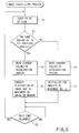
- FIG. 6 is a flowchart showing procedures executed by the sections 30, 31 and 29 of the image stabilizing unit 25.
- step S1 the point-of-view monitoring section 30 calculates coordinates (x, y) of the point of view on the display screen. Then, the image stabilizing and display correction calculating section 29 calculates amounts of movement ⁇ X and ⁇ Y of the point of view from coordinates (x, y) obtained at a current period and coordinates (x, y) obtained at the previous period. If the amounts of movement ⁇ X and ⁇ Y are within a predetermined range, it is judged that the worker 5 continues to looking at the same point of an object in the workplace (S2) (the coordinates (x, y) of the point of view regarded as unchanged on the display screen).
- step S3 the worker's movement calculating section 31 reads the accelerations ⁇ x , ⁇ y and ⁇ z in the three directions from the acceleration sensor 18 and calculates amounts of movement L x , L y and L z in the x-, y- and z-axis directions from the previous period.
- step S4 the position of the image data 28 displayed on the display screen 21a, obtained through the camera 12, is entirely moved in the direction in which the calculated amounts of movement L x , L y and L z of the worker 5 are canceled, in order to suppress the fluctuation of the image of the object displayed on the display screen 21a due to a movement or swing of the worker 5.
- a mark of the point of view of the worker is displayed at the coordinates (x, y) on the display screen.
- the position of the image data 28 as a whole is corrected, so that the image of the object on the display screen may not deviate.
- the image data 28 after correction is supplied to the image reproducing unit 26 as stabilized image data 33.
- step S1 When the image stabilizing process described above is completed, after it is determined that a unit time has been elapsed, the flow returns to step S1 and coordinates (x, y) of the point of view in the next period is read.
- step S6 the worker's movement calculating section 31 reads the accelerations ⁇ x , ⁇ y and ⁇ z in the three directions from the acceleration sensor 18 and calculates amounts of movement L x , L y and L z in the x-, y- and z-axis directions from the previous period.
- the amounts of movement L x , L y and L z are initialized to [0] and further the amounts of movement ⁇ X and ⁇ Y are set to [0] without calculating the amounts of movement ⁇ X and ⁇ Y (step S7). Correction of the position of the image data 28 as a whole to be displayed on the display screen 21a is not executed.
- step S5 the flow returns to step S1 and coordinates (x, y) of the point of view in the next period is read.
- image data 28a obtained by the camera 12 at time t (indicated by the solid line) is changed to image data 28b at time t+1 after lapse of a period (indicated by the dot line) due to vibration or movement of the head 5a.
- the image data 28b on the screen at the time t+1 is moved entirely toward an upper right portion as indicated by the dotted arrow, so that the position of the image of the point of view 43a at the time t+1 can coincide with that of the point of view at the time t. According to the movement, a non-display region 36 as indicated by slant lines is generated.
- the point of view of the worker 5 does not move in the display screen 21a of the CRT display device 21. Therefore, the manager 2 can observe a stable image.
- the designated position calculating unit 27 comprises a touched position coordinate detecting section 37, a projection surface position calculating section 38 and a laser emission angle calculating section 39.
- the touched position coordinate detecting section 37 detects the touched position on the touch panel 22 and transmits the detected position to the projection surface position calculating section 38.
- the projection surface position calculating section 38 calculates designated coordinates (x 1 , y 1 ) on an image screen 40 shown in FIG. 9 (the display screen 21a of the CRT display device 21), i.e., stabilized image data input from the image stabilizing unit 25.
- the designated coordinates thus calculated are transmitted to the laser emission angle calculating section 39.
- the laser emission angle calculating section 39 constitutes in a virtual space a camera model having a focal distance f equivalent to the focal distance f of the camera 12. It calculates three-dimensional emission angles a and b formed between the upper semi-transparent mirror 15 shown in FIG. 9 and the laser beam 13a emitted from the laser source 13 mounted on the helmet 7 of the worker 5.
- the manager 2 designates through the touch panel 22 a point which he/she instructs the worker 5 in the workplace 4 to look at and gives instructions through the microphone 24, the laser beam 13a is irradiated on the corresponding position designated by the manager on the actual object in the workplace 4.
- the manager 2 can accurately indicate the position to the worker 5 in the workplace 4.
- the manager 2 in the managing room 1 and the worker 5 in the remote workplace 4 can promptly exchange information with reality.
- the system of this embodiment can be applied to guard, patrol, factory maintenance, an emergency measure, etc.
- the manager 2 can simultaneously observe a plurality of workers 5 in different workplaces 4. In this case, skillful managers need not go patrolling to the workplaces along with workers, resulting in personnel reduction.
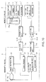
- FIG. 10 is a block diagram schematically showing an image telecommunication system according to another embodiment of the present invention.
- the same portions as those in the image telecommunication system shown in FIG. 4 are identified by the same reference numerals as those used in FIG. 4, and descriptions thereof are omitted.
- a worker's device 6 incorporates an image stabilizing unit 25a to stably display image data 28 obtained by a camera 12 of the worker's device 6 on a display screen 21a of a CRT display device.
- FIG. 11 shows a detailed structure of the image stabilizing unit 25a incorporated in the worker's device 6.
- the image stabilizing unit 25a does not have a lock mode setting section.
- the image, acceleration and point of view obtained by the camera 12, an acceleration sensor 18 and an eye tracking sensor 14 in the worker's device 6 are input to the image stabilizing unit 25a.
- the image stabilizing unit 25 stabilizes image data 28 supplied from the camera 12, using the acceleration and point of view and generates stabilized image 33.
- the stabilized image 33 is transmitted to the manager's device 3 via a transmitting unit 9a.
- An image reproducing unit 26 of the manager's device 3 receives the stabilized image 33 from the worker's device 6 and displays it on the display screen 21a of the CRT display device 21.
- an image stop command is directly transmitted to the image reproducing unit 26 by depressing a stop button displayed on a touch panel 22.
- the present invention is not limited to the above embodiments.
- a laser source is used as the position indicating device 13 for indicating an object the position designated by the manager 2.
- the position indicating device 13 may project the designated position on the eyeglasses of the worker's device 6. In this case, since the worker 5 looks at the object through the eyeglasses on which the designated position is indicated, he/she can accurately recognize the point designated by the manager 2.
- the camera 12 is mounted on the helmet 7 of the worker 5, when the worker 5 inclines the head 5a, the image displayed on the display screen 21a of the manager's device 3 is also inclined. To prevent this, the inclination angle of the camera 12 is calculated from the acceleration angles ⁇ x , ⁇ y and ⁇ z in the three-dimensional directions detected by the acceleration sensor 18, thereby correcting the inclination of the image displayed on the display screen 21a.
- the image telecommunication system of the present invention detects the point of view and movement of the worker 5, and stably displays to the manager 2 the situations observed by the worker 5 in the remote workplace 4.
- the instructions can be transmitted to the worker 5 more accurately along with the voice.
Abstract
Description
Claims (21)
- An image telecommunication system comprising:a worker's device (6), put on a worker, for collecting an image of an object present in a field of view of the worker and transmitting it outside the worker's device; anda manager's device (3), placed in a remote place distant from the worker's device, for receiving and displaying the image of the object transmitted from the worker's device on a display screen, characterized in that:the worker's device includes detecting means (14) for detecting a point of view of the worker; andthe manager's device includes displaying means for displaying the detected point of view on the display screen, when it is determined that the worker looks at the object substantially continuously.
- The image telecommunication system according to claim 1, characterized in that:the detecting means (14) detect a point of view of the worker at fixed periods; andthe display means determine that the worker looks at the object substantially continuously and displays the detected point of view on the display screen, when a difference between a point of view detected in a current period and a point of view detected in a previous period is within a predetermined range.
- The image telecommunication system according to claim 1, characterized in that the manager's device further includes fluctuation suppressing means for suppressing fluctuation of the image displayed on the display screen, when it is determined that the worker looks at the object substantially continuously.
- An image telecommunication system comprising:a worker's device (6), put on a worker, for collecting an image of an object present in a field of view of the worker and transmitting it outside the worker's device; anda manager's device (3), placed in a remote place distant from the worker's device, for receiving and displaying the image of the object transmitted from the worker's device on a display screen, characterized in that:the worker's device includes detecting means (14) for detecting a point of view of the worker; andthe manager's device includes fluctuation suppressing means for suppressing fluctuation of the image displayed on the display screen, when it is determined that the worker looks at the object substantially continuously.
- The image telecommunication system according to claim 4, characterized in that:the detecting means detect a point of view of the worker at fixed periods;the worker's device further includes movement detecting means (18) for detecting amounts of movement of the worker at fixed periods; andthe manager's device further includes means for, when a difference between a point of view detected in a current period and a point of view detected in a previous period is within a predetermined range (35), determining that the worker looks at the object substantially continuously, and moving the image of the object displayed on the display screen in a direction in which the difference is canceled.
- An image telecommunication system comprising:a worker's device (6), put on a worker, for collecting an image of an object present in a field of view of the worker and transmitting it outside the worker's device; anda manager's device (3), placed in a remote place distant from the worker's device, for receiving and displaying the image of the object transmitted from the worker's device on a display screen, characterized in that:the manager's device includes transmitting means (27, 11b) for transmitting a designated position, designated in a state where the image is displayed on the display screen, to the worker's device; andthe worker's device includes indicating means (13) for indicating a position on the object corresponding to the designated position received from the manager's device.
- The image telecommunication system according to claim 6, characterized in that:the manager's device further includes means (24, 11b) for converting a voice, input in a state where the image is displayed, to a voice signal and transmitting the voice signal to the worker's device; andthe worker's device further includes means (19) for outputting a voice corresponding to the voice signal received from the manager's device.
- The image telecommunication system according to claim 6, characterized in that:the worker's device further includes detecting means (14) for detecting a point of view of the worker; andthe manager's device further includes fluctuation suppressing means (25) for suppressing fluctuation of the image displayed on the display screen, when it is determined that the worker looks at the object substantially continuously.
- The image telecommunication system according to claim 6, characterized in that: the worker's device further includes detecting means (14) for detecting a point of view of the worker and fluctuation suppressing means (25a) for suppressing fluctuation of the image displayed on the display screen, when it is determined that the worker looks at the object substantially continuously.
- The image telecommunication system according to claim 8, characterized in that:the detecting means (14) detect a point of view of the worker at fixed periods;the worker's device further includes movement detecting means (18) for detecting amounts of movement of the worker at fixed periods; andthe manager's device further includes means (25) for, when a difference between a point of view detected in a current period and a point of view detected in a previous period is within a predetermined range, determining that the worker looks at the object substantially continuously, and moving the image of the object displayed on the display screen in a direction in which the difference is canceled.
- The image telecommunication system according to claim 6, characterized in that the indicating means irradiate a laser beam onto the position on the object.
- The image telecommunication system according to claim 10, characterized in that the indicating means irradiate a laser beam onto the position on the object.
- The image telecommunication system according to claim 6, characterized in that the indicating means project the position on the object onto eyeglasses put on the worker.
- The image telecommunication system according to claim 10, characterized in that the indicating means project the position on the object onto eyeglasses put on the worker.
- The image telecommunication system according to claim 10, characterized in that the image of the object present in the field of view of the worker is collected by a camera (12) mounted on a front portion of a helmet (7) put on the worker.
- The image telecommunication system according to claim 15, characterized in that the movement detecting means comprise an acceleration sensor (18) mounted on the helmet and integrating means for integrating twice an acceleration detected by the acceleration sensor.
- The image telecommunication system according to claim 15, characterized in that the movement detecting means is a gyroscope mounted on the helmet.
- The image telecommunication system according to claim 15, characterized in that the detecting means is an eye tracking sensor, mounted on a front portion of the helmet, for detecting a position of a pupil of the worker.
- The image telecommunication system according to claim 16, characterized in that the manager's device further includes calculating means for calculating an inclination angle of the camera from the acceleration detected by the acceleration sensor and correcting means for correcting an inclination of the image displayed on the display screen using the calculated inclination angle.
- The image telecommunication system according to claim 10, characterized in that the manager's device further includes lock mode setting means (32) for temporarily stopping movement of the image displayed on the display screen, when a lock operation is performed in a state where the image is displayed.
- The image telecommunication system according to claim 10, characterized in that the designated position is designated in the manager's device through a touch panel (22) provided in front of the display screen.
Applications Claiming Priority (3)
| Application Number | Priority Date | Filing Date | Title |
|---|---|---|---|
| JP05924897A JP3217723B2 (en) | 1997-03-13 | 1997-03-13 | Telecommunications system and telecommunications method |
| JP5924897 | 1997-03-13 | ||
| JP59248/97 | 1997-03-13 |
Publications (2)
| Publication Number | Publication Date |
|---|---|
| EP0865207A2 true EP0865207A2 (en) | 1998-09-16 |
| EP0865207A3 EP0865207A3 (en) | 1999-10-06 |
Family
ID=13107905
Family Applications (1)
| Application Number | Title | Priority Date | Filing Date |
|---|---|---|---|
| EP98301824A Withdrawn EP0865207A3 (en) | 1997-03-13 | 1998-03-12 | Image telecommunication system |
Country Status (4)
| Country | Link |
|---|---|
| US (1) | US6342915B1 (en) |
| EP (1) | EP0865207A3 (en) |
| JP (1) | JP3217723B2 (en) |
| KR (1) | KR100268614B1 (en) |
Cited By (4)
| Publication number | Priority date | Publication date | Assignee | Title |
|---|---|---|---|---|
| WO2001084838A1 (en) * | 2000-04-28 | 2001-11-08 | Swisscom Mobile Ag | Method and system for video conferences |
| EP1585066A2 (en) * | 2000-03-31 | 2005-10-12 | Fuji Photo Film Co., Ltd. | Work data collection method |
| CN101355682B (en) * | 2007-07-23 | 2011-03-16 | 中兴通讯股份有限公司 | Method for automatically regulating speed of whole network of wideband private wire conference television system |
| JP2015052895A (en) * | 2013-09-06 | 2015-03-19 | 株式会社東芝 | Information processor and method of processing information |
Families Citing this family (42)
| Publication number | Priority date | Publication date | Assignee | Title |
|---|---|---|---|---|
| KR20010036306A (en) * | 1999-10-07 | 2001-05-07 | 이재현 | a security system and a security method using mobile communication network |
| JP4288843B2 (en) * | 2000-10-25 | 2009-07-01 | 沖電気工業株式会社 | Remote work support system |
| US6900777B1 (en) * | 2001-01-03 | 2005-05-31 | Stryker Corporation | Infrared audio/video interface for head-mounted display |
| US7474335B2 (en) * | 2001-01-31 | 2009-01-06 | International Business Machines Corporation | Method, apparatus and program storage device for image position stabilizer |
| US8126276B2 (en) * | 2001-02-21 | 2012-02-28 | International Business Machines Corporation | Business method for selectable semantic codec pairs for very low data-rate video transmission |
| US20030038878A1 (en) * | 2001-08-21 | 2003-02-27 | Lee Chinmei Chen | Remotely initiated surveillance |
| US7466992B1 (en) | 2001-10-18 | 2008-12-16 | Iwao Fujisaki | Communication device |
| US7158121B2 (en) * | 2001-10-19 | 2007-01-02 | American Standard International Inc. | Enhanced touch-screen display system |
| US6894617B2 (en) * | 2002-05-04 | 2005-05-17 | Richman Technology Corporation | Human guard enhancing multiple site integrated security system |
| US20030206100A1 (en) | 2002-05-04 | 2003-11-06 | Lawrence Richman | Method and protocol for real time security system |
| US6753899B2 (en) | 2002-09-03 | 2004-06-22 | Audisoft | Method and apparatus for telepresence |
| US7090134B2 (en) * | 2003-03-04 | 2006-08-15 | United Parcel Service Of America, Inc. | System for projecting a handling instruction onto a moving item or parcel |
| US7063256B2 (en) * | 2003-03-04 | 2006-06-20 | United Parcel Service Of America | Item tracking and processing systems and methods |
| US7307651B2 (en) * | 2003-10-16 | 2007-12-11 | Mark A. Chew | Two-way mobile video/audio/data interactive companion (MVIC) system |
| US20050212760A1 (en) * | 2004-03-23 | 2005-09-29 | Marvit David L | Gesture based user interface supporting preexisting symbols |
| US20050278446A1 (en) * | 2004-05-27 | 2005-12-15 | Jeffery Bryant | Home improvement telepresence system and method |
| US7561717B2 (en) * | 2004-07-09 | 2009-07-14 | United Parcel Service Of America, Inc. | System and method for displaying item information |
| JP4582329B2 (en) * | 2005-07-22 | 2010-11-17 | 日本電気株式会社 | Virtual video signal generation method and transmission / reception terminal |
| US20070204014A1 (en) * | 2006-02-28 | 2007-08-30 | John Wesley Greer | Mobile Webcasting of Multimedia and Geographic Position for a Real-Time Web Log |
| JP4952204B2 (en) * | 2006-11-13 | 2012-06-13 | コニカミノルタホールディングス株式会社 | Remote work support system and display method thereof |
| US8339248B2 (en) * | 2007-04-27 | 2012-12-25 | Carroll David W | Automated audio operation support device and methods |
| US20100066802A1 (en) * | 2008-09-16 | 2010-03-18 | Brian Dross | Remote communications device and method for facilitating manual operations |
| US8289290B2 (en) * | 2009-07-20 | 2012-10-16 | Sony Ericsson Mobile Communications Ab | Touch sensing apparatus for a mobile device, mobile device and method for touch operation sensing |
| JP5251813B2 (en) * | 2009-09-28 | 2013-07-31 | ブラザー工業株式会社 | Work support system, head mounted display and program |
| US9323250B2 (en) | 2011-01-28 | 2016-04-26 | Intouch Technologies, Inc. | Time-dependent navigation of telepresence robots |
| US9098611B2 (en) * | 2012-11-26 | 2015-08-04 | Intouch Technologies, Inc. | Enhanced video interaction for a user interface of a telepresence network |
| JP5247854B2 (en) | 2011-07-06 | 2013-07-24 | 株式会社インスピーディア | Collection system and collection method |
| US9361021B2 (en) | 2012-05-22 | 2016-06-07 | Irobot Corporation | Graphical user interfaces including touchpad driving interfaces for telemedicine devices |
| WO2013176762A1 (en) | 2012-05-22 | 2013-11-28 | Intouch Technologies, Inc. | Social behavior rules for a medical telepresence robot |
| US20180048750A1 (en) * | 2012-06-15 | 2018-02-15 | Muzik, Llc | Audio/video wearable computer system with integrated projector |
| US8929573B2 (en) * | 2012-09-14 | 2015-01-06 | Bose Corporation | Powered headset accessory devices |
| EP2897481B1 (en) | 2012-09-18 | 2018-01-31 | Bell Sports, Inc. | Protective headwear assembly having a built-in camera |
| US9265458B2 (en) | 2012-12-04 | 2016-02-23 | Sync-Think, Inc. | Application of smooth pursuit cognitive testing paradigms to clinical drug development |
| US9549583B2 (en) | 2013-01-04 | 2017-01-24 | Bell Sports, Inc. | Helmet with integrated electronic components |
| US9380976B2 (en) | 2013-03-11 | 2016-07-05 | Sync-Think, Inc. | Optical neuroinformatics |
| JP6157170B2 (en) * | 2013-03-28 | 2017-07-05 | 大阪瓦斯株式会社 | Monitoring support system |
| JP6030170B2 (en) * | 2015-03-10 | 2016-11-24 | 東芝エレベータ株式会社 | Elevator maintenance work support device |
| JP6666997B2 (en) * | 2016-07-14 | 2020-03-18 | ヤマハ発動機株式会社 | Work support system for mounting work area and work support method for mounting work area |
| WO2018173445A1 (en) * | 2017-03-23 | 2018-09-27 | ソニー株式会社 | Information processing device, information processing method, information processing system, and program |
| US10471478B2 (en) | 2017-04-28 | 2019-11-12 | United Parcel Service Of America, Inc. | Conveyor belt assembly for identifying an asset sort location and methods of utilizing the same |
| CN113519166A (en) * | 2019-03-04 | 2021-10-19 | 麦克赛尔株式会社 | Remote operation indicating system and installation type equipment |
| JP7318258B2 (en) | 2019-03-26 | 2023-08-01 | コベルコ建機株式会社 | Remote control system and remote control server |
Citations (2)
| Publication number | Priority date | Publication date | Assignee | Title |
|---|---|---|---|---|
| GB2251780A (en) * | 1990-06-30 | 1992-07-22 | Kesteven Hargreaves Limited | Camera mounting apparatus |
| WO1997004597A1 (en) * | 1995-07-14 | 1997-02-06 | Sensormatic Electronics Corporation | Video compression system |
Family Cites Families (14)
| Publication number | Priority date | Publication date | Assignee | Title |
|---|---|---|---|---|
| JP2907988B2 (en) * | 1990-10-05 | 1999-06-21 | 株式会社日立製作所 | Wide television receiver |
| JP3183928B2 (en) | 1992-01-24 | 2001-07-09 | オリンパス光学工業株式会社 | Camera shake prevention device for photographing equipment |
| US5544649A (en) * | 1992-03-25 | 1996-08-13 | Cardiomedix, Inc. | Ambulatory patient health monitoring techniques utilizing interactive visual communication |
| DE69331158T2 (en) * | 1992-04-03 | 2002-08-29 | Hitachi Ltd | Multipoint video transmission system for satellite communication |
| GB2267625B (en) * | 1992-05-20 | 1996-08-21 | Northern Telecom Ltd | Video services |
| US6023288A (en) * | 1993-03-31 | 2000-02-08 | Cairns & Brother Inc. | Combination head-protective helmet and thermal imaging apparatus |
| US5619183A (en) * | 1994-09-12 | 1997-04-08 | Richard C. Ziegra | Video audio data remote system |
| US5594498A (en) * | 1994-10-14 | 1997-01-14 | Semco, Inc. | Personal audio/video surveillance system |
| US5583795A (en) * | 1995-03-17 | 1996-12-10 | The United States Of America As Represented By The Secretary Of The Army | Apparatus for measuring eye gaze and fixation duration, and method therefor |
| US5742335A (en) * | 1995-07-19 | 1998-04-21 | Cannon; Michael W. | Examination system for architectural structure exteriors |
| US5864481A (en) * | 1996-01-22 | 1999-01-26 | Raytheon Company | Integrated, reconfigurable man-portable modular system |
| US5844601A (en) * | 1996-03-25 | 1998-12-01 | Hartness Technologies, Llc | Video response system and method |
| US6097429A (en) * | 1997-08-01 | 2000-08-01 | Esco Electronics Corporation | Site control unit for video security system |
| US5933479A (en) * | 1998-10-22 | 1999-08-03 | Toyoda Machinery Usa Corp. | Remote service system |
-
1997
- 1997-03-13 JP JP05924897A patent/JP3217723B2/en not_active Expired - Lifetime
-
1998
- 1998-03-12 US US09/038,629 patent/US6342915B1/en not_active Expired - Lifetime
- 1998-03-12 EP EP98301824A patent/EP0865207A3/en not_active Withdrawn
- 1998-03-13 KR KR1019980009993A patent/KR100268614B1/en not_active IP Right Cessation
Patent Citations (2)
| Publication number | Priority date | Publication date | Assignee | Title |
|---|---|---|---|---|
| GB2251780A (en) * | 1990-06-30 | 1992-07-22 | Kesteven Hargreaves Limited | Camera mounting apparatus |
| WO1997004597A1 (en) * | 1995-07-14 | 1997-02-06 | Sensormatic Electronics Corporation | Video compression system |
Cited By (7)
| Publication number | Priority date | Publication date | Assignee | Title |
|---|---|---|---|---|
| EP1585066A2 (en) * | 2000-03-31 | 2005-10-12 | Fuji Photo Film Co., Ltd. | Work data collection method |
| EP1585066A3 (en) * | 2000-03-31 | 2008-11-05 | FUJIFILM Corporation | Work data collection method |
| WO2001084838A1 (en) * | 2000-04-28 | 2001-11-08 | Swisscom Mobile Ag | Method and system for video conferences |
| US6717607B1 (en) | 2000-04-28 | 2004-04-06 | Swisscom Mobile Ag | Method and system for video conferences |
| AU772400B2 (en) * | 2000-04-28 | 2004-04-29 | Swisscom Mobile Ag | Method and system for video conferences |
| CN101355682B (en) * | 2007-07-23 | 2011-03-16 | 中兴通讯股份有限公司 | Method for automatically regulating speed of whole network of wideband private wire conference television system |
| JP2015052895A (en) * | 2013-09-06 | 2015-03-19 | 株式会社東芝 | Information processor and method of processing information |
Also Published As
| Publication number | Publication date |
|---|---|
| JPH10257475A (en) | 1998-09-25 |
| EP0865207A3 (en) | 1999-10-06 |
| US6342915B1 (en) | 2002-01-29 |
| KR100268614B1 (en) | 2000-10-16 |
| JP3217723B2 (en) | 2001-10-15 |
| KR19980080563A (en) | 1998-11-25 |
Similar Documents
| Publication | Publication Date | Title |
|---|---|---|
| US6342915B1 (en) | Image telecommunication system | |
| AU2018330755B2 (en) | Displaying a virtual image of a building information model | |
| JP6565465B2 (en) | Image display device, computer program, and image display system | |
| US5900849A (en) | Display headset | |
| US7773098B2 (en) | Virtual reality presentation apparatus and method | |
| WO2016118371A1 (en) | Mixed reality system | |
| US7342648B2 (en) | Information sensing and sharing system for supporting rescue operations from burning buildings | |
| US11544030B2 (en) | Remote work-support system | |
| JP7371626B2 (en) | Information processing device, information processing method, and program | |
| JPH10198506A (en) | System for detecting coordinate | |
| EP3822923A1 (en) | Maintenance assistance system, maintenance assistance method, program, method for generating processed image, and processed image | |
| JP5309499B2 (en) | Security camera device in elevator | |
| US11137600B2 (en) | Display device, display control method, and display system | |
| JP5605178B2 (en) | Traffic vehicle monitoring system and vehicle monitoring camera | |
| JPH05289739A (en) | Three-dimensional image processor and teleoperating system | |
| JP2023123557A (en) | Head-mounted display and image display system | |
| JPH09330489A (en) | Equipment monitoring method and its device | |
| JP4689344B2 (en) | Information processing method and information processing apparatus | |
| KR101247316B1 (en) | Security system | |
| JPH06167687A (en) | Projector | |
| KR20220058122A (en) | Collaborative systems and methods for field and remote site using HMD | |
| KR20210147680A (en) | Video Surveillance Apparatus for Congestion Control | |
| JP2021077127A (en) | Management system and management method using eyewear device | |
| US20220012868A1 (en) | Maintenance support system, maintenance support method, program, method for generating processed image, and processed image | |
| KR20230133623A (en) | A system for sharing a location between users in a VR space and a method for preventing collisions between users in a VR space using the same |
Legal Events
| Date | Code | Title | Description |
|---|---|---|---|
| PUAI | Public reference made under article 153(3) epc to a published international application that has entered the european phase |
Free format text: ORIGINAL CODE: 0009012 |
|
| 17P | Request for examination filed |
Effective date: 19980407 |
|
| AK | Designated contracting states |
Kind code of ref document: A2 Designated state(s): DE GB |
|
| AX | Request for extension of the european patent |
Free format text: AL;LT;LV;MK;RO;SI |
|
| PUAL | Search report despatched |
Free format text: ORIGINAL CODE: 0009013 |
|
| AK | Designated contracting states |
Kind code of ref document: A3 Designated state(s): AT BE CH DE DK ES FI FR GB GR IE IT LI LU MC NL PT SE |
|
| AX | Request for extension of the european patent |
Free format text: AL;LT;LV;MK;RO;SI |
|
| RIC1 | Information provided on ipc code assigned before grant |
Free format text: 6H 04N 7/18 A, 6H 04N 7/14 B |
|
| AKX | Designation fees paid |
Free format text: DE GB |
|
| STAA | Information on the status of an ep patent application or granted ep patent |
Free format text: STATUS: THE APPLICATION IS DEEMED TO BE WITHDRAWN |
|
| 18D | Application deemed to be withdrawn |
Effective date: 20100324 |