EP0864994A2 - Combined range laser scanner - Google Patents
Combined range laser scanner Download PDFInfo
- Publication number
- EP0864994A2 EP0864994A2 EP98103024A EP98103024A EP0864994A2 EP 0864994 A2 EP0864994 A2 EP 0864994A2 EP 98103024 A EP98103024 A EP 98103024A EP 98103024 A EP98103024 A EP 98103024A EP 0864994 A2 EP0864994 A2 EP 0864994A2
- Authority
- EP
- European Patent Office
- Prior art keywords
- range
- laser
- scanning
- illumination system
- assembly
- Prior art date
- Legal status (The legal status is an assumption and is not a legal conclusion. Google has not performed a legal analysis and makes no representation as to the accuracy of the status listed.)
- Granted
Links
- 238000005286 illumination Methods 0.000 claims abstract description 63
- 230000003287 optical effect Effects 0.000 claims abstract description 46
- 238000000034 method Methods 0.000 claims abstract description 17
- 238000001579 optical reflectometry Methods 0.000 claims abstract description 6
- 230000005855 radiation Effects 0.000 claims description 16
- 230000003213 activating effect Effects 0.000 claims description 10
- 230000009977 dual effect Effects 0.000 description 12
- 238000010586 diagram Methods 0.000 description 4
- 238000005516 engineering process Methods 0.000 description 3
- 239000004065 semiconductor Substances 0.000 description 3
- 238000010276 construction Methods 0.000 description 2
- 238000001514 detection method Methods 0.000 description 2
- 241000321728 Tritogonia verrucosa Species 0.000 description 1
- 230000000712 assembly Effects 0.000 description 1
- 238000000429 assembly Methods 0.000 description 1
- 230000003750 conditioning effect Effects 0.000 description 1
- 230000000994 depressogenic effect Effects 0.000 description 1
- CPBQJMYROZQQJC-UHFFFAOYSA-N helium neon Chemical compound [He].[Ne] CPBQJMYROZQQJC-UHFFFAOYSA-N 0.000 description 1
- 238000007493 shaping process Methods 0.000 description 1
- 239000007787 solid Substances 0.000 description 1
- 238000010408 sweeping Methods 0.000 description 1
Images


Classifications
-
- G—PHYSICS
- G06—COMPUTING; CALCULATING OR COUNTING
- G06K—GRAPHICAL DATA READING; PRESENTATION OF DATA; RECORD CARRIERS; HANDLING RECORD CARRIERS
- G06K7/00—Methods or arrangements for sensing record carriers, e.g. for reading patterns
- G06K7/10—Methods or arrangements for sensing record carriers, e.g. for reading patterns by electromagnetic radiation, e.g. optical sensing; by corpuscular radiation
- G06K7/10544—Methods or arrangements for sensing record carriers, e.g. for reading patterns by electromagnetic radiation, e.g. optical sensing; by corpuscular radiation by scanning of the records by radiation in the optical part of the electromagnetic spectrum
- G06K7/10821—Methods or arrangements for sensing record carriers, e.g. for reading patterns by electromagnetic radiation, e.g. optical sensing; by corpuscular radiation by scanning of the records by radiation in the optical part of the electromagnetic spectrum further details of bar or optical code scanning devices
- G06K7/10881—Methods or arrangements for sensing record carriers, e.g. for reading patterns by electromagnetic radiation, e.g. optical sensing; by corpuscular radiation by scanning of the records by radiation in the optical part of the electromagnetic spectrum further details of bar or optical code scanning devices constructional details of hand-held scanners
-
- G—PHYSICS
- G06—COMPUTING; CALCULATING OR COUNTING
- G06K—GRAPHICAL DATA READING; PRESENTATION OF DATA; RECORD CARRIERS; HANDLING RECORD CARRIERS
- G06K7/00—Methods or arrangements for sensing record carriers, e.g. for reading patterns
- G06K7/10—Methods or arrangements for sensing record carriers, e.g. for reading patterns by electromagnetic radiation, e.g. optical sensing; by corpuscular radiation
- G06K7/10544—Methods or arrangements for sensing record carriers, e.g. for reading patterns by electromagnetic radiation, e.g. optical sensing; by corpuscular radiation by scanning of the records by radiation in the optical part of the electromagnetic spectrum
- G06K7/10554—Moving beam scanning
- G06K7/10564—Light sources
- G06K7/10574—Multiple sources
-
- G—PHYSICS
- G06—COMPUTING; CALCULATING OR COUNTING
- G06K—GRAPHICAL DATA READING; PRESENTATION OF DATA; RECORD CARRIERS; HANDLING RECORD CARRIERS
- G06K7/00—Methods or arrangements for sensing record carriers, e.g. for reading patterns
- G06K7/10—Methods or arrangements for sensing record carriers, e.g. for reading patterns by electromagnetic radiation, e.g. optical sensing; by corpuscular radiation
- G06K7/10544—Methods or arrangements for sensing record carriers, e.g. for reading patterns by electromagnetic radiation, e.g. optical sensing; by corpuscular radiation by scanning of the records by radiation in the optical part of the electromagnetic spectrum
- G06K7/10792—Special measures in relation to the object to be scanned
- G06K7/10801—Multidistance reading
- G06K7/10811—Focalisation
-
- G—PHYSICS
- G06—COMPUTING; CALCULATING OR COUNTING
- G06K—GRAPHICAL DATA READING; PRESENTATION OF DATA; RECORD CARRIERS; HANDLING RECORD CARRIERS
- G06K2207/00—Other aspects
- G06K2207/1013—Multi-focal
Definitions
- the present invention relates generally to a combined range laser scanner and method for electro-optically reading indicia such as bar codes having parts of different light reflectivity. More particularly, the subject invention pertains to a combined range laser scanner and method as described which utilizes two or more laser diode optical illumination systems focused at different working ranges.
- One preferred embodiment comprises two laser optical illumination systems, a first system optimized for contact operation, and a second system optimized for longer distance scanning, and the two laser scanning systems are integrated into one combined range laser scanner.
- the laser scanning system disclosed in U.S. Patent 4,496,831 includes a portable hand-held scanning head which may be embodied in various shapes but preferably has a gun shaped housing made of lightweight plastic.
- a handle and barrel portion are provided to house the various components of the scanning system therein.
- Within the barrel portion are mounted a miniature light source, a miniature optic train including focusing lenses and a scanning system for directing light from the light source across a bar code symbol, and miniature sensing means for detecting reflected light from the bar code symbol being scanned.
- the miniature light source can comprise a laser tube such as a coaxial helium neon laser tube, or an LED, or preferably a semiconductor laser diode which is considerably smaller and lighter than a laser tube, thus reducing the required size and weight of the scanning head and making the scanning head easier to handle and more maneuverable.
- Light generated by the light source passes through the optic train which directs the beam onto the scanning system which is mounted within the barrel portion of the scanning head.
- the scanning system sweeps the laser beam across the bar code symbol and comprises at least one scanning stepping motor or resonating or vibrating bar or scanner for sweeping the beam lengthwise across the symbol, and may comprise two motors wherein the second motor sweeps the beam widthwise across the symbol.
- Light reflecting mirrors are mounted on the motor shaft or shafts to direct the beam through the outlet port to the symbol.
- a sonar range finder can be used for detecting the range to a target in the field of view.
- the selection means comprises a manually operated selection means selectively actuated by an operator, such as a trigger which includes first and second trigger detent positions which are selectively actuated by the operator.
- the scanning mirror includes a flat scanning mirror which is driven by a scanning motor.
- the short range laser illumination optical system comprises a short range visible laser diode assembly positioned directly in front of the scanning mirror.
- the longer range laser illumination optical system includes a fold mirror positioned adjacent the short range visible laser diode, and a long range visible laser diode assembly positioned to direct laser radiation to the fold mirror for reflection onto the scanning mirror.
- the short range laser illumination system and longer range laser illumination system could comprise a single integrated laser diode assembly designed to operate in either a short or longer range mode of operation positioned directly in front of the scanning mirror.
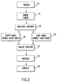
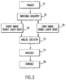
- a range finder 14 detects the distance to the bar code symbol.
- the range finder 14 can comprise a signal processing circuit for analyzing the amplitude and frequency of a reflected signal when the longer range scanning system is temporarily actuated in a range finding operation. A bar code located at a farther distance will result in a detector output signal of lower amplitude with higher frequency components, and conversely a detector output signal with a higher amplitude and lower frequency components at shorter ranges. Accordingly, based upon the amplitude and frequency components of the detected signal during a range finding operation, either the short or longer range illumination system is selected.
- the range finder can comprise a Polaroid sonar type of range finder as used in commercial cameras. Based upon the output of the range finder, switching circuitry 16 selects which visible laser diode circuit is to be used, either a short range visible laser diode 18 or a longer range visible laser diode 20.
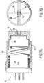
- the laser diode package 74 would house two different laser diodes, one positioned directly behind each laser aperture 80', 80'. It should be realized that the laser diode element itself is extremely small, such that the side-by-side positioning of two such laser diodes in the laser diode package 74 is easily accommodated.
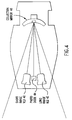
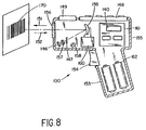
- the reader 100 may also function as a portable computer terminal, and include a keyboard 148 and a display 149, such as described in the previously noted U.S. Patent 4,409,470.
- a suitable lens 157 may be used to focus the scanned beam onto the bar code symbol at an appropriate reference plane.
- a light source 146 such as a semiconductor laser diode is positioned to introduce a light beam into the axis of the lens 157, and the beam passes through a partially silvered mirror 147 and other lenses or beam-shaping structure as needed, along with an oscillating mirror 159, which is attached to a scanning motor 160 activated when the trigger 154 is pulled.
- an aiming light may be included in the optical system. The aiming light, if needed, produces a visible-light spot which may be fixed, or scanned just like the laser beam; the user employs this visible light to aim the reader unit at the symbol before pulling the trigger 154.
Abstract
Description
Claims (12)
- A combined range laser scanner assembly (100) for electro-optically reading indicia (170) having parts of different light reflectivity on a target located at a variable distance from the assembly, comprising:a. a scanning mirror (54) for causing a laser beam to be scanned over a field of view;b. a short range laser illumination system (18, 40, 50) for short range scanning operations;c. a long range, longer than the short range, laser illumination system (20, 42, 60, 62) for long range scanning operations;d. a collection optical system (46, 66) for collecting light reflected from the scanned field of view;e. an optical detector (44, 68) for detecting light directed thereto by the collection optical system, and for generating electrical signals corresponding to the reflected light; andf. automatically operable selection means (14, 16) for selectively automatically activating the short range laser illumination system for operation at short ranges in the field of view, and for selectively automatically activating the long range laser illumination system for operation at long ranges in the field of view.
- The assembly as claimed in claim 1, wherein said selection means includes a range finder (14) for detecting the distance of the target from the assembly.
- The assembly as claimed in claim 2, wherein said range finder (14) is a sonar range finder.
- The assembly as claimed in claim 1 or 2, wherein the selections means (14) includes a signal processing circuit for analyzing the amplitude and frequency of a reflected signal when the long range laser illumination system is temporarily actuated in a range finding operation.
- The assembly as claimed in any of the preceding claims, wherein said scanning mirror (54) includes a flat mirror which is driven by a scanner motor.
- The assembly as claimed in any of the preceding claims, wherein said collection optical system (46, 66) includes a collection mirror which focuses scanned laser radiation reflected from the field of view onto said optical detector (44, 68).
- The assembly as claimed in any of the preceding claims, wherein said short range laser illumination system includes a short range visible light laser diode (50) positioned in front of said scanning mirror.
- The assembly as claimed in claim 7, wherein said long range laser illumination system includes a folding mirror (60) positioned by the short range visible light laser diode (50), and a long range visible light laser diode (62) positioned to direct laser radiation to said folding mirror (60) for reflection of the laser radiation onto said scanning mirror (54).
- The assembly as claimed in claim 1, wherein said short range laser illumination system has a range up to approximately 0.6 m (two feet) from the laser scanner assembly, and said longer range laser illumination system has a range of approximately 0.6 m (two feet) to 3.66 m (twelve feet) from the laser scanner assembly.
- A combined method of scanning a laser beam, comprising:a. scanning a laser beam over a field of view with a scanning mirror (54);b. selectively automatically activating a short range laser illumination system (18, 40, 50) for operation at short ranges in the field of view for illuminating the scanning mirror for short range scanning operations by the short range laser illumination optical system;c. selectively automatically activating a long range laser illumination system (20, 42, 60, 62) for operation at long ranges in the field of view for illuminating the scanning mirror for long range, longer than the short range, scanning operation by the long range laser illumination optical system;d. collecting scanned laser radiation reflected from the scanned field of view with a collection optical system (46, 66); ande. detecting scanned laser radiation directed to an optical detector (44, 68) by the collection optical system.
- The method as claimed in claim 10, wherein said step of selectively automatically activating includes detecting with a range finder (14) the range to a target in the field of view.
- The method as claimed in claim 10, wherein said step of illuminating the scanning mirror (54) for a short range scanning includes a range up to approximately 0.6 m (two feet), and said step of illuminating the scanning mirror for a long range includes a range of approximately 0.6 m (two feet) to 3.66 m (twelve feet).
Applications Claiming Priority (3)
| Application Number | Priority Date | Filing Date | Title |
|---|---|---|---|
| US71777091A | 1991-06-14 | 1991-06-14 | |
| US717770 | 1991-06-14 | ||
| EP91122403A EP0517958B1 (en) | 1991-06-14 | 1991-12-30 | Combined range laser scanner |
Related Parent Applications (2)
| Application Number | Title | Priority Date | Filing Date |
|---|---|---|---|
| EP91122403.8 Division | 1991-12-30 | ||
| EP91122403A Division EP0517958B1 (en) | 1991-06-14 | 1991-12-30 | Combined range laser scanner |
Publications (3)
| Publication Number | Publication Date |
|---|---|
| EP0864994A2 true EP0864994A2 (en) | 1998-09-16 |
| EP0864994A3 EP0864994A3 (en) | 2000-03-29 |
| EP0864994B1 EP0864994B1 (en) | 2006-03-29 |
Family
ID=24883415
Family Applications (2)
| Application Number | Title | Priority Date | Filing Date |
|---|---|---|---|
| EP98103024A Expired - Lifetime EP0864994B1 (en) | 1991-06-14 | 1991-12-30 | Combined range laser scanner |
| EP91122403A Expired - Lifetime EP0517958B1 (en) | 1991-06-14 | 1991-12-30 | Combined range laser scanner |
Family Applications After (1)
| Application Number | Title | Priority Date | Filing Date |
|---|---|---|---|
| EP91122403A Expired - Lifetime EP0517958B1 (en) | 1991-06-14 | 1991-12-30 | Combined range laser scanner |
Country Status (7)
| Country | Link |
|---|---|
| US (3) | US5420411A (en) |
| EP (2) | EP0864994B1 (en) |
| JP (1) | JPH05182002A (en) |
| AT (2) | ATE322048T1 (en) |
| CA (1) | CA2056272C (en) |
| DE (2) | DE69130060T2 (en) |
| ES (1) | ES2119755T3 (en) |
Cited By (2)
| Publication number | Priority date | Publication date | Assignee | Title |
|---|---|---|---|---|
| DE10009493A1 (en) * | 2000-02-29 | 2001-08-30 | Sick Ag | scanner |
| US7092664B2 (en) | 2000-12-22 | 2006-08-15 | Eastman Kodak Company | Digital printing or copying machine |
Families Citing this family (95)
| Publication number | Priority date | Publication date | Assignee | Title |
|---|---|---|---|---|
| US5949056A (en) * | 1986-09-10 | 1999-09-07 | Norand Corporation | Method and apparatus for optically reading an information pattern |
| JP3077616B2 (en) | 1997-01-31 | 2000-08-14 | 富士通株式会社 | Barcode reading method |
| US5581067A (en) * | 1990-05-08 | 1996-12-03 | Symbol Technologies, Inc. | Compact bar code scanning module with shock protection |
| US6595420B1 (en) * | 1990-09-10 | 2003-07-22 | Metrologic Instruments, Inc. | Automatically-activated body-wearable laser scanning bar code symbol reading system having data-transmission activation switch |
| US5616908A (en) | 1991-09-17 | 1997-04-01 | Metrologic Instruments, Inc. | Automatic countertop laser scanner with flickering laser scanner beam for improved visibility thereof during bar code symbol reading |
| US5340973A (en) * | 1990-09-17 | 1994-08-23 | Metrologic Instruments, Inc. | Automatic laser scanning system and method of reading bar code symbols using same |
| US6286760B1 (en) | 1994-08-17 | 2001-09-11 | Metrologic Instruments, Inc. | Automatic hand-supportable laser projection scanner for omni-directional reading of bar code symbols within a narrowly confined scanning volume |
| US6257492B1 (en) | 1990-09-10 | 2001-07-10 | Peter Bressler | Combination hand-held and counter-top omni-directional scanner |
| US5796091A (en) * | 1993-11-24 | 1998-08-18 | Metrologic Instruments, Inc. | Automatic hand-supportable omnidirectional laser projection scanner with handle-controllable projection axis |
| US6631842B1 (en) * | 2000-06-07 | 2003-10-14 | Metrologic Instruments, Inc. | Method of and system for producing images of objects using planar laser illumination beams and image detection arrays |
| US6607133B2 (en) | 1990-09-10 | 2003-08-19 | Metrologic Instruments, Inc. | Automatically-activated hand-supportable laser scanning bar code symbol reading system with data transmission activation switch |
| US6651890B2 (en) | 1990-09-10 | 2003-11-25 | Sung Ho Byun | Combination hand-held and counter-top omnidirectional scanner |
| US5942743A (en) * | 1994-08-17 | 1999-08-24 | Metrologic Instruments, Inc. | Portable automatic hand-supportable omnidirectional laser projection scanner with power conserving control system |
| US6283375B1 (en) | 1990-09-10 | 2001-09-04 | Metrologic Instruments, Inc. | Automatically-activated hand-supportable laser scanning bar code symbol reading system with data transmission activation switch |
| US5844227A (en) * | 1993-11-24 | 1998-12-01 | Metrologic Instruments, Inc. | Automatic hand-supportable omnidirectional laser projection scanner with scan-head directed projection axis for intuitive hand-supported omnidirectional scanning of bar code symbols within a narrowly confined scanning volume extending thereabout |
| US6182898B1 (en) | 1993-11-24 | 2001-02-06 | Metrologic Instruments, Inc. | Bar code scanner with intuitive head aiming and collimated scan volume |
| US5340971A (en) * | 1990-09-17 | 1994-08-23 | Metrologic Instruments, Inc. | Automatic bar code reading system having selectable long range and short range modes of operation |
| US7156310B2 (en) * | 1990-09-17 | 2007-01-02 | Metrologic Instruments, Inc. | Automatically-activated hand-supportable laser scanning bar code symbol reading system with data transmission activation switch |
| US5742038A (en) * | 1990-09-28 | 1998-04-21 | Symbol Technologies, Inc. | Beam shaping for optical scanners |
| CA2056272C (en) * | 1991-06-14 | 2001-10-16 | Patrick Salatto, Jr. | Combined range laser scanner |
| US6382513B1 (en) * | 1991-07-25 | 2002-05-07 | Symbol Technologies, Inc. | Optical scanner with segmented collection mirror |
| US6948662B2 (en) | 1991-07-25 | 2005-09-27 | Symbol Technologies, Inc. | Two-dimensional optical code scanner with scanning pattern having region of greater apparent brightness for assisting alignment of scanning pattern |
| US5883375A (en) * | 1991-09-17 | 1999-03-16 | Metrologic Instruments, Inc. | Bar code symbol scanner having fixed and hand-held modes |
| US6189793B1 (en) | 1992-06-12 | 2001-02-20 | Metrologic Instruments, Inc. | Automatic laser projection scanner with improved activation controlling mechanism |
| IT1264733B1 (en) * | 1993-11-04 | 1996-10-04 | Datalogic Spa | LASER READING DEVICE OR SCANNER FOR READING CHARACTERS HAVING A DIFFERENT DEGREE OF REFLECTENCE, IN PARTICULAR OF CODES A |
| US6604684B1 (en) | 1993-11-24 | 2003-08-12 | Metrologic Instruments Inc. | Automatic optical projection scanner for omni-directional reading of bar code symbols within a confined scanning volume |
| US6860427B1 (en) | 1993-11-24 | 2005-03-01 | Metrologic Instruments, Inc. | Automatic optical projection scanner for omni-directional reading of bar code symbols within a confined scanning volume |
| JP3265804B2 (en) * | 1994-03-18 | 2002-03-18 | 富士通株式会社 | Barcode reader |
| US5537431A (en) * | 1994-06-15 | 1996-07-16 | International Business Machines Corporation | Method and apparatus for bar code reading and decoding |
| US7051922B2 (en) | 1994-08-17 | 2006-05-30 | Metrologic Instruments, Inc. | Compact bioptical laser scanning system |
| CA2580841C (en) * | 1995-03-17 | 2008-08-05 | Symbol Technologies, Inc. | System and method for reading optically encoded information |
| US6029893A (en) * | 1995-05-22 | 2000-02-29 | Symbol Technologies, Inc. | Optical scanner having a reflected light collector including holographic optical elements |
| US6811086B1 (en) * | 1995-07-20 | 2004-11-02 | Fujitsu Limited | Stand for pivotably mounting an optical reading device |
| DE768614T1 (en) * | 1995-10-10 | 1997-12-18 | Symbol Technologies Inc | Retroreflective scanning modules for electro-optical readers |
| US6357662B1 (en) * | 1996-01-02 | 2002-03-19 | Intermec Ip Corp. | Hand-held, dual-mode asset tracking reader with light-activated switch |
| US6034379A (en) * | 1996-03-01 | 2000-03-07 | Intermec Ip Corp. | Code reader having replaceable optics assemblies supporting multiple illuminators |
| DE19748583A1 (en) * | 1996-11-05 | 1998-06-04 | Psc Inc Webster | Laser scanner with multiple scanning areas |
| ES2222474T3 (en) * | 1996-12-31 | 2005-02-01 | Datalogic S.P.A. | PROCEDURE AND APPARATUS FOR MEASURING THE VOLUME OF AN OBJECT. |
| DE19700281A1 (en) * | 1997-01-07 | 1998-07-09 | Sick Ag | Optical code reader with an optical scanner |
| US6976626B2 (en) | 1997-09-16 | 2005-12-20 | Metrologic Instruments, Inc. | Wireless bar code symbol driven portable data terminal (PDT) system adapted for single handed operation |
| US7097105B2 (en) * | 1998-12-03 | 2006-08-29 | Metrologic Instruments, Inc. | Automatically-activated hand-supportable omni-directional laser scanning bar code symbol reader having a user-selectable linear scanning menu-reading mode supported by a stroboscopically-pulsed omni-directional laser scanning pattern for improved bar code symbol navigation and alignment during menu-reading operations |
| US7111786B2 (en) * | 1998-12-03 | 2006-09-26 | Metrologic Instruments, Inc. | Automatically-activated wireless hand-supportable laser scanning bar code symbol reading system with data transmission activation switch and automatic communication range dependent control |
| EP1226541A2 (en) * | 1999-10-04 | 2002-07-31 | Welch Allyn Data Collection, Inc. | Imaging module for optical reader |
| US20030029917A1 (en) * | 1999-10-04 | 2003-02-13 | Hand Held Products, Inc. | Optical reader for imaging module |
| US7270274B2 (en) | 1999-10-04 | 2007-09-18 | Hand Held Products, Inc. | Imaging module comprising support post for optical reader |
| US6478452B1 (en) * | 2000-01-19 | 2002-11-12 | Coherent, Inc. | Diode-laser line-illuminating system |
| US7100832B2 (en) * | 2000-04-18 | 2006-09-05 | Metrologic Instruments, Inc. | Bioptical laser scanning system providing 360° of omnidirectional bar code symbol scanning coverage at point of sale station |
| US20030132291A1 (en) * | 2002-01-11 | 2003-07-17 | Metrologic Instruments, Inc. | Point of sale (POS) station having bar code reading system with integrated internet-enabled customer-kiosk terminal |
| TW478277B (en) * | 2000-08-28 | 2002-03-01 | Umax Data Systems Inc | Image scanning method to set the photosensitive module at different positions for scanning images |
| JP3581644B2 (en) * | 2000-09-05 | 2004-10-27 | キヤノン株式会社 | Image reading apparatus, control method for the apparatus, and storage medium |
| US7128266B2 (en) * | 2003-11-13 | 2006-10-31 | Metrologic Instruments. Inc. | Hand-supportable digital imaging-based bar code symbol reader supporting narrow-area and wide-area modes of illumination and image capture |
| US7464877B2 (en) * | 2003-11-13 | 2008-12-16 | Metrologic Instruments, Inc. | Digital imaging-based bar code symbol reading system employing image cropping pattern generator and automatic cropped image processor |
| US7083102B2 (en) * | 2002-01-11 | 2006-08-01 | Metrologic Instruments, Inc. | Bioptical laser scanner for six-sided 360° Pos-based scanning |
| US7055747B2 (en) * | 2002-06-11 | 2006-06-06 | Hand Held Products, Inc. | Long range optical reader |
| US8596542B2 (en) | 2002-06-04 | 2013-12-03 | Hand Held Products, Inc. | Apparatus operative for capture of image data |
| US7219843B2 (en) * | 2002-06-04 | 2007-05-22 | Hand Held Products, Inc. | Optical reader having a plurality of imaging modules |
| US7090132B2 (en) * | 2002-06-11 | 2006-08-15 | Hand Held Products, Inc. | Long range optical reader |
| US20030222147A1 (en) | 2002-06-04 | 2003-12-04 | Hand Held Products, Inc. | Optical reader having a plurality of imaging modules |
| US7086596B2 (en) * | 2003-01-09 | 2006-08-08 | Hand Held Products, Inc. | Decoder board for an optical reader utilizing a plurality of imaging formats |
| US20040112963A1 (en) * | 2002-12-16 | 2004-06-17 | Ncr Corporation | Bar code scanner |
| US6820811B1 (en) * | 2002-12-16 | 2004-11-23 | Ncr Corporation | Dual focal length bar code scanner |
| US20040229195A1 (en) * | 2003-03-18 | 2004-11-18 | Leapfrog Enterprises, Inc. | Scanning apparatus |
| JP4589921B2 (en) * | 2003-04-02 | 2010-12-01 | サン・マイクロシステムズ・インコーポレーテッド | Optical communication between facing semiconductor chips |
| WO2005012859A1 (en) * | 2003-07-30 | 2005-02-10 | Optris Gmbh | Device for non-contact temperature measurement |
| DE102004017504A1 (en) * | 2004-04-08 | 2005-10-27 | Sick Ag | Method and apparatus for reading a bar code |
| US7216811B2 (en) * | 2004-04-16 | 2007-05-15 | Microscan Systems Incorporated | Barcode scanner with linear automatic gain control (AGC), modulation transfer function detector, and selectable noise filter |
| US7416127B2 (en) * | 2005-02-24 | 2008-08-26 | Psion Teklogix Systems Inc. | Range-finding system for a portable image reader |
| US7628331B2 (en) * | 2005-09-29 | 2009-12-08 | Symbol Technologies, Inc. | Method and system for optimizing scanner performance |
| US8002183B2 (en) * | 2005-10-20 | 2011-08-23 | Metrologic Instruments, Inc. | Scanner flipper integrity indicator |
| US8181878B2 (en) * | 2006-01-25 | 2012-05-22 | Cognex Technology And Investment Corporation | Method and apparatus for providing a focus indication for optical imaging of visual codes |
| US7597263B2 (en) * | 2006-07-31 | 2009-10-06 | Symbol Technologies, Inc. | Imaging reader with target proximity sensor |
| US7832641B2 (en) * | 2007-05-24 | 2010-11-16 | Metrologic Instruments, Inc. | Scanner switched to active state by sensed movement in quiescent scanning mechanism |
| US8820645B2 (en) * | 2007-09-28 | 2014-09-02 | Symbol Technologies, Inc. | Method and system for optimizing system settings of a laser scanner control system |
| US8302864B2 (en) | 2007-12-28 | 2012-11-06 | Cognex Corporation | Method and apparatus using aiming pattern for machine vision training |
| US8646689B2 (en) | 2007-12-28 | 2014-02-11 | Cognex Corporation | Deformable light pattern for machine vision system |
| US8134116B2 (en) | 2009-01-12 | 2012-03-13 | Cognex Corporation | Modular focus system for image based code readers |
| US9418269B2 (en) * | 2009-08-12 | 2016-08-16 | Hand Held Products, Inc. | Laser scanning indicia reading terminal having variable lens assembly |
| US8390909B2 (en) | 2009-09-23 | 2013-03-05 | Metrologic Instruments, Inc. | Molded elastomeric flexural elements for use in a laser scanning assemblies and scanners, and methods of manufacturing, tuning and adjusting the same |
| US8059324B2 (en) * | 2009-09-23 | 2011-11-15 | Metrologic Instruments, Inc. | Scan element for use in scanning light and method of making the same |
| US8294969B2 (en) | 2009-09-23 | 2012-10-23 | Metrologic Instruments, Inc. | Scan element for use in scanning light and method of making the same |
| US8177134B2 (en) * | 2010-07-21 | 2012-05-15 | Hand Held Products, Inc. | Multiple range indicia reader with single trigger actuation |
| US8561903B2 (en) | 2011-01-31 | 2013-10-22 | Hand Held Products, Inc. | System operative to adaptively select an image sensor for decodable indicia reading |
| US8459557B2 (en) | 2011-03-10 | 2013-06-11 | Metrologic Instruments, Inc. | Dual laser scanning code symbol reading system employing automatic object presence detector for automatic laser source selection |
| US8757494B2 (en) * | 2011-09-27 | 2014-06-24 | Symbol Technologies, Inc. | Illumination system in imaging scanner |
| US8608071B2 (en) | 2011-10-17 | 2013-12-17 | Honeywell Scanning And Mobility | Optical indicia reading terminal with two image sensors |
| US8947590B2 (en) | 2011-11-22 | 2015-02-03 | Cognex Corporation | Vision system camera with mount for multiple lens types |
| US11366284B2 (en) | 2011-11-22 | 2022-06-21 | Cognex Corporation | Vision system camera with mount for multiple lens types and lens module for the same |
| US10498933B2 (en) | 2011-11-22 | 2019-12-03 | Cognex Corporation | Camera system with exchangeable illumination assembly |
| US8915439B2 (en) | 2012-02-06 | 2014-12-23 | Metrologic Instruments, Inc. | Laser scanning modules embodying silicone scan element with torsional hinges |
| US8746563B2 (en) | 2012-06-10 | 2014-06-10 | Metrologic Instruments, Inc. | Laser scanning module with rotatably adjustable laser scanning assembly |
| US9746636B2 (en) | 2012-10-19 | 2017-08-29 | Cognex Corporation | Carrier frame and circuit board for an electronic device |
| US9530037B1 (en) | 2015-07-20 | 2016-12-27 | Datalogic ADC, Inc. | Toggling activation of lasers in scanner systems |
| US9798912B1 (en) * | 2016-09-26 | 2017-10-24 | Symbol Technologies, Llc | Imaging module and reader for, and method of, reading targets by image capture with a substantially constant resolution over an extended range of working distances |
| JP6989747B2 (en) * | 2018-02-27 | 2022-01-12 | Idec株式会社 | Information reading device and information reading method |
| KR102507876B1 (en) * | 2020-12-28 | 2023-03-14 | 주식회사 대오비전 | 3-Dimension Scanner Platform and Scanning Device Having the Same |
Citations (4)
| Publication number | Priority date | Publication date | Assignee | Title |
|---|---|---|---|---|
| US4496831A (en) * | 1980-02-29 | 1985-01-29 | Symbol Technologies, Inc. | Portable laser scanning system and scanning methods |
| JPS6391791A (en) * | 1986-10-06 | 1988-04-22 | Matsushita Electric Ind Co Ltd | Bar code detecting device |
| US4920255A (en) * | 1988-10-31 | 1990-04-24 | Stephen C. Gabeler | Automatic incremental focusing scanner system |
| EP0414281A2 (en) * | 1985-02-28 | 1991-02-27 | Symbol Technologies, Inc. | Portable laser diode scanning head |
Family Cites Families (24)
| Publication number | Priority date | Publication date | Assignee | Title |
|---|---|---|---|---|
| US3989348A (en) * | 1975-04-28 | 1976-11-02 | Rca Corporation | Optical scanner with large depth of focus |
| JPS5330223A (en) * | 1976-09-01 | 1978-03-22 | Nippon Denso Co Ltd | Automaitc code reading unit |
| US4251798A (en) * | 1978-05-31 | 1981-02-17 | Symbol Technologies | Portable laser scanning arrangement for and method of evaluating and validating bar code symbols |
| US4387297B1 (en) * | 1980-02-29 | 1995-09-12 | Symbol Technologies Inc | Portable laser scanning system and scanning methods |
| US4369361A (en) * | 1980-03-25 | 1983-01-18 | Symbol Technologies, Inc. | Portable, stand-alone, desk-top laser scanning workstation for intelligent data acquisition terminal and method of scanning |
| US4758717A (en) * | 1982-01-25 | 1988-07-19 | Symbol Technologies, Inc. | Narrow-bodied, single-and twin-windowed portable laser scanning head for reading bar code symbols |
| DE3242219C1 (en) * | 1982-11-15 | 1984-02-16 | Erwin Sick Gmbh Optik-Elektronik, 7808 Waldkirch | Optical brand recognition device |
| US4560862A (en) * | 1983-04-26 | 1985-12-24 | Skan-A-Matic Corp. | System for optical scanning over a large depth of field |
| US4591242A (en) * | 1984-02-13 | 1986-05-27 | International Business Machines Corp. | Optical scanner having multiple, simultaneous scan lines with different focal lengths |
| US4843222A (en) * | 1986-05-29 | 1989-06-27 | Eastman Kodak Company | Bar code reader for reading bar code symbols at different distances |
| US4877949A (en) * | 1986-08-08 | 1989-10-31 | Norand Corporation | Hand-held instant bar code reader system with automated focus based on distance measurements |
| US4816661A (en) * | 1986-12-22 | 1989-03-28 | Symbol Technologies, Inc. | Scan pattern generators for bar code symbol readers |
| US4808804A (en) * | 1987-01-28 | 1989-02-28 | Symbol Technologies, Inc. | Bar code symbol readers with variable spot size and/or working distance |
| US4816659A (en) * | 1987-10-13 | 1989-03-28 | Control Module Inc. | Bar code reader head |
| JPH059782Y2 (en) * | 1987-12-04 | 1993-03-10 | ||
| US4871904A (en) * | 1987-12-28 | 1989-10-03 | Symbol Technologies, Inc. | Multidirectional optical scanner |
| US4939355A (en) * | 1988-01-22 | 1990-07-03 | Spectra-Physics, Inc. | Automatic package label scanner |
| US5122644A (en) * | 1988-11-17 | 1992-06-16 | Alps Electric Co., Ltd. | Optical code reading device with autofocussing |
| JPH0744313B2 (en) * | 1989-02-24 | 1995-05-15 | 日本電信電話株式会社 | Semiconductor laser device |
| US5115121A (en) * | 1990-01-05 | 1992-05-19 | Control Module Inc. | Variable-sweep bar code reader |
| US5073702A (en) * | 1990-03-26 | 1991-12-17 | Ncr Corporation | Multiple beam bar code scanner |
| IT1242584B (en) * | 1990-10-09 | 1994-05-16 | Datalogic Spa | LASER BEAM BAR CODE READER. |
| US5062115A (en) * | 1990-12-28 | 1991-10-29 | Xerox Corporation | High density, independently addressable, surface emitting semiconductor laser/light emitting diode arrays |
| CA2056272C (en) * | 1991-06-14 | 2001-10-16 | Patrick Salatto, Jr. | Combined range laser scanner |
-
1991
- 1991-11-27 CA CA002056272A patent/CA2056272C/en not_active Expired - Lifetime
- 1991-12-30 AT AT98103024T patent/ATE322048T1/en not_active IP Right Cessation
- 1991-12-30 EP EP98103024A patent/EP0864994B1/en not_active Expired - Lifetime
- 1991-12-30 DE DE69130060T patent/DE69130060T2/en not_active Expired - Lifetime
- 1991-12-30 EP EP91122403A patent/EP0517958B1/en not_active Expired - Lifetime
- 1991-12-30 AT AT91122403T patent/ATE170306T1/en not_active IP Right Cessation
- 1991-12-30 DE DE69133519T patent/DE69133519T2/en not_active Expired - Lifetime
- 1991-12-30 ES ES91122403T patent/ES2119755T3/en not_active Expired - Lifetime
-
1992
- 1992-05-20 JP JP4126949A patent/JPH05182002A/en active Pending
-
1993
- 1993-07-29 US US08/098,243 patent/US5420411A/en not_active Expired - Lifetime
-
1995
- 1995-05-30 US US08/452,995 patent/US5723851A/en not_active Expired - Lifetime
-
1997
- 1997-11-07 US US08/965,820 patent/US5945658A/en not_active Expired - Lifetime
Patent Citations (4)
| Publication number | Priority date | Publication date | Assignee | Title |
|---|---|---|---|---|
| US4496831A (en) * | 1980-02-29 | 1985-01-29 | Symbol Technologies, Inc. | Portable laser scanning system and scanning methods |
| EP0414281A2 (en) * | 1985-02-28 | 1991-02-27 | Symbol Technologies, Inc. | Portable laser diode scanning head |
| JPS6391791A (en) * | 1986-10-06 | 1988-04-22 | Matsushita Electric Ind Co Ltd | Bar code detecting device |
| US4920255A (en) * | 1988-10-31 | 1990-04-24 | Stephen C. Gabeler | Automatic incremental focusing scanner system |
Non-Patent Citations (1)
| Title |
|---|
| PATENT ABSTRACTS OF JAPAN vol. 012, no. 329 (P-754), 7 September 1988 (1988-09-07) & JP 63 091791 A (MATSUSHITA ELECTRIC IND CO LTD), 22 April 1988 (1988-04-22) * |
Cited By (3)
| Publication number | Priority date | Publication date | Assignee | Title |
|---|---|---|---|---|
| DE10009493A1 (en) * | 2000-02-29 | 2001-08-30 | Sick Ag | scanner |
| US6827269B2 (en) | 2000-02-29 | 2004-12-07 | Sick Ag | Scanner |
| US7092664B2 (en) | 2000-12-22 | 2006-08-15 | Eastman Kodak Company | Digital printing or copying machine |
Also Published As
| Publication number | Publication date |
|---|---|
| US5945658A (en) | 1999-08-31 |
| EP0864994A3 (en) | 2000-03-29 |
| EP0864994B1 (en) | 2006-03-29 |
| DE69133519D1 (en) | 2006-05-18 |
| EP0517958A2 (en) | 1992-12-16 |
| US5723851A (en) | 1998-03-03 |
| US5420411A (en) | 1995-05-30 |
| DE69130060D1 (en) | 1998-10-01 |
| ATE170306T1 (en) | 1998-09-15 |
| CA2056272A1 (en) | 1992-12-15 |
| EP0517958A3 (en) | 1992-12-23 |
| ATE322048T1 (en) | 2006-04-15 |
| DE69133519T2 (en) | 2006-11-23 |
| JPH05182002A (en) | 1993-07-23 |
| DE69130060T2 (en) | 1999-04-29 |
| ES2119755T3 (en) | 1998-10-16 |
| EP0517958B1 (en) | 1998-08-26 |
| CA2056272C (en) | 2001-10-16 |
Similar Documents
| Publication | Publication Date | Title |
|---|---|---|
| US5723851A (en) | Combined range, turn parallel beam assembly with common focusing element for scanning systems | |
| US5396055A (en) | Hand held bar code reader with keyboard, display and processor | |
| US5969321A (en) | Hand-held optically readable information set reader with operation over a range of distances | |
| US5321246A (en) | Bar code scanner with RF coupling to base terminal and automatic turn-off upon decode | |
| JP3056590B2 (en) | Optical scanner with increased depth of focus | |
| US5367152A (en) | Method of reading indicia from either side of scanner housing | |
| US6138915A (en) | Hand-held optically readable character set reader having automatic focus control for operation over a range of distances | |
| US5117098A (en) | Multi-position trigger for control over aiming and symbol reading in a portable laser diode scanning head | |
| JPH03179579A (en) | Electro-optical sign reader | |
| US5142131A (en) | Hand-held bar code reader | |
| EP0752680A1 (en) | Optical scanners having dual surface optical elements for dual working ranges | |
| US5484990A (en) | Multiple depth of field laser optical scanner | |
| US5475208A (en) | Barcode scanner having a dead zone reducing system and a multifocal length collector | |
| US5187353A (en) | Bar code symbol scanner utilizing monitor photodiode of laser diode package as a photoreceiver | |
| US5233170A (en) | Bar code symbol scanner utilizing monitor photodiode of laser diode package as a photoreceiver | |
| EP0575894B1 (en) | Retro-reflective scanner with return path free of collection optics | |
| EP0414452B1 (en) | Hand-held bar code reader | |
| WO2001082214A1 (en) | Multi-format bar code reader | |
| EP0366899B1 (en) | Retro-reflective laser diode scanner with beam position control | |
| KR950014168B1 (en) | Pual rage laser scanning apparatus and its method | |
| JP3152724B2 (en) | Optical system | |
| JP3058941B2 (en) | Optical scanning device | |
| JPH11203393A (en) | Optical information reader | |
| JPH06103391A (en) | Bar-code reader |
Legal Events
| Date | Code | Title | Description |
|---|---|---|---|
| PUAI | Public reference made under article 153(3) epc to a published international application that has entered the european phase |
Free format text: ORIGINAL CODE: 0009012 |
|
| 17P | Request for examination filed |
Effective date: 19980220 |
|
| AC | Divisional application: reference to earlier application |
Ref document number: 517958 Country of ref document: EP |
|
| AK | Designated contracting states |
Kind code of ref document: A2 Designated state(s): AT DE ES FR GB IT |
|
| PUAL | Search report despatched |
Free format text: ORIGINAL CODE: 0009013 |
|
| AK | Designated contracting states |
Kind code of ref document: A3 Designated state(s): AT DE ES FR GB IT |
|
| 17Q | First examination report despatched |
Effective date: 20030318 |
|
| GRAP | Despatch of communication of intention to grant a patent |
Free format text: ORIGINAL CODE: EPIDOSNIGR1 |
|
| GRAS | Grant fee paid |
Free format text: ORIGINAL CODE: EPIDOSNIGR3 |
|
| GRAA | (expected) grant |
Free format text: ORIGINAL CODE: 0009210 |
|
| AC | Divisional application: reference to earlier application |
Ref document number: 0517958 Country of ref document: EP Kind code of ref document: P |
|
| AK | Designated contracting states |
Kind code of ref document: B1 Designated state(s): AT DE ES FR GB IT |
|
| PG25 | Lapsed in a contracting state [announced via postgrant information from national office to epo] |
Ref country code: IT Free format text: LAPSE BECAUSE OF FAILURE TO SUBMIT A TRANSLATION OF THE DESCRIPTION OR TO PAY THE FEE WITHIN THE PRESCRIBED TIME-LIMIT;WARNING: LAPSES OF ITALIAN PATENTS WITH EFFECTIVE DATE BEFORE 2007 MAY HAVE OCCURRED AT ANY TIME BEFORE 2007. THE CORRECT EFFECTIVE DATE MAY BE DIFFERENT FROM THE ONE RECORDED. Effective date: 20060329 Ref country code: AT Free format text: LAPSE BECAUSE OF FAILURE TO SUBMIT A TRANSLATION OF THE DESCRIPTION OR TO PAY THE FEE WITHIN THE PRESCRIBED TIME-LIMIT Effective date: 20060329 |
|
| REG | Reference to a national code |
Ref country code: GB Ref legal event code: FG4D |
|
| REF | Corresponds to: |
Ref document number: 69133519 Country of ref document: DE Date of ref document: 20060518 Kind code of ref document: P |
|
| PG25 | Lapsed in a contracting state [announced via postgrant information from national office to epo] |
Ref country code: ES Free format text: LAPSE BECAUSE OF FAILURE TO SUBMIT A TRANSLATION OF THE DESCRIPTION OR TO PAY THE FEE WITHIN THE PRESCRIBED TIME-LIMIT Effective date: 20060710 |
|
| ET | Fr: translation filed | ||
| PLBE | No opposition filed within time limit |
Free format text: ORIGINAL CODE: 0009261 |
|
| STAA | Information on the status of an ep patent application or granted ep patent |
Free format text: STATUS: NO OPPOSITION FILED WITHIN TIME LIMIT |
|
| 26N | No opposition filed |
Effective date: 20070102 |
|
| PGFP | Annual fee paid to national office [announced via postgrant information from national office to epo] |
Ref country code: FR Payment date: 20101203 Year of fee payment: 20 |
|
| PGFP | Annual fee paid to national office [announced via postgrant information from national office to epo] |
Ref country code: GB Payment date: 20101123 Year of fee payment: 20 |
|
| PGFP | Annual fee paid to national office [announced via postgrant information from national office to epo] |
Ref country code: DE Payment date: 20101230 Year of fee payment: 20 |
|
| REG | Reference to a national code |
Ref country code: DE Ref legal event code: R071 Ref document number: 69133519 Country of ref document: DE |
|
| REG | Reference to a national code |
Ref country code: DE Ref legal event code: R071 Ref document number: 69133519 Country of ref document: DE |
|
| REG | Reference to a national code |
Ref country code: GB Ref legal event code: PE20 Expiry date: 20111229 |
|
| PG25 | Lapsed in a contracting state [announced via postgrant information from national office to epo] |
Ref country code: GB Free format text: LAPSE BECAUSE OF EXPIRATION OF PROTECTION Effective date: 20111229 |
|
| PG25 | Lapsed in a contracting state [announced via postgrant information from national office to epo] |
Ref country code: DE Free format text: LAPSE BECAUSE OF EXPIRATION OF PROTECTION Effective date: 20111231 |