EP0864867A2 - Improved analyzer throughput featuring through-the-tip analysis - Google Patents
Improved analyzer throughput featuring through-the-tip analysis Download PDFInfo
- Publication number
- EP0864867A2 EP0864867A2 EP98301734A EP98301734A EP0864867A2 EP 0864867 A2 EP0864867 A2 EP 0864867A2 EP 98301734 A EP98301734 A EP 98301734A EP 98301734 A EP98301734 A EP 98301734A EP 0864867 A2 EP0864867 A2 EP 0864867A2
- Authority
- EP
- European Patent Office
- Prior art keywords
- tip
- liquid
- light
- radiation
- dispensing
- Prior art date
- Legal status (The legal status is an assumption and is not a legal conclusion. Google has not performed a legal analysis and makes no representation as to the accuracy of the status listed.)
- Granted
Links
Images


Classifications
-
- G—PHYSICS
- G01—MEASURING; TESTING
- G01N—INVESTIGATING OR ANALYSING MATERIALS BY DETERMINING THEIR CHEMICAL OR PHYSICAL PROPERTIES
- G01N35/00—Automatic analysis not limited to methods or materials provided for in any single one of groups G01N1/00 - G01N33/00; Handling materials therefor
- G01N35/00029—Automatic analysis not limited to methods or materials provided for in any single one of groups G01N1/00 - G01N33/00; Handling materials therefor provided with flat sample substrates, e.g. slides
-
- G—PHYSICS
- G01—MEASURING; TESTING
- G01N—INVESTIGATING OR ANALYSING MATERIALS BY DETERMINING THEIR CHEMICAL OR PHYSICAL PROPERTIES
- G01N21/00—Investigating or analysing materials by the use of optical means, i.e. using sub-millimetre waves, infrared, visible or ultraviolet light
- G01N21/01—Arrangements or apparatus for facilitating the optical investigation
- G01N21/03—Cuvette constructions
-
- G—PHYSICS
- G01—MEASURING; TESTING
- G01N—INVESTIGATING OR ANALYSING MATERIALS BY DETERMINING THEIR CHEMICAL OR PHYSICAL PROPERTIES
- G01N35/00—Automatic analysis not limited to methods or materials provided for in any single one of groups G01N1/00 - G01N33/00; Handling materials therefor
- G01N35/10—Devices for transferring samples or any liquids to, in, or from, the analysis apparatus, e.g. suction devices, injection devices
- G01N2035/1027—General features of the devices
- G01N2035/1048—General features of the devices using the transfer device for another function
- G01N2035/1062—General features of the devices using the transfer device for another function for testing the liquid while it is in the transfer device
Definitions
- This invention relates to a new use of old apparatus, and a new dispensing station, that allow spectrophotometric analysis to be done on blood samples before they are conventionally tested in a dry or wet assay.
- Spectrophotometric analysis is commonly applied to many liquids to determine the contents. Such analysis is particularly useful if done with near infrared radiation, due to the latter's ability to discriminate between a target analyte and other substances.
- the analyzer comprising a dispensing station and at least one test station for detecting a target substance in a patient sample
- the dispensing station comprising: an aspirator probe; a tip mounted on the probe, for collecting a biological liquid from a primary collection container and for dispensing at least a portion of the collected liquid onto or into a test element; and means for creating a partial pressure or partial vacuum within the probe and the tip.
- Still another aspect of the solution of the problem features a dispensing station for use in a clinical analyzer, comprising:
- Yet another advantageous feature is that results are achieved in less time since no incubation time is required for the spectrophotometric analysis.
- the invention is hereinafter described in connection with preferred embodiments, in which a preferred (and conventional) translucent disposable tip is used on a preferred (and conventional) analyzer aspirator, and a preferred light-tight enclosure connected to the spectrophotometer by passageways using fiber optics, to analyze for targets representing patient sample quality in blood serum or plasma. Additionally, however, the invention can be used regardless of the type of translucent or transparent tip, aspirator, liquid, or light-tight enclosure that is used, regardless of the optical system providing passageway of the light to and from the spectrophotometer, and regardless of the target substance being detected, so long as the target has sufficient NIR and adjacent visible radiation absorption.
- the target substance can be a traditional substance tested for concentration in an analyzer heretofore on a slide test element, for example, albumin or glucose.
- the liquid can be whole blood, urine or cerebral spinal fluid as well.
- the tip can be permanent rather than disposable, and an open lens system could be used in place of fiber optics, to focus the light to the light-tight enclosure and then to the detecting station.
- spectrophotometer used with the invention. The reason is that any spectrophotometer is useful, provided it generates and detects via transmission, radiation emitted in the near infrared and adjacent visible light regions with sufficient spectra precision.
- near infrared and adjacent visible means, radiation between 400 and 2500 nm, and most preferably, between 475 and 1075 nm. These wavelengths are advantageous as they provide sufficient spectral penetration of the disposable tip as well as sufficient spectral absorption from target analytes. 475 nm is considered to be particularly useful for bilirubin detection by this invention.
- Useful materials for the tips that allow desired spectral penetration are those commonly used to manufacture disposable tips (polypropylene or polyethylene).
- spectrophotometric means a technique that captures the spectral response over a range of wavelengths and correlates a response for each wavelength in the range.
- photometric means an analysis of light radiation to correlate a response to only a particular wavelength.
- a “spectrophotometer” then is the apparatus that does this spectrophotometric analysis.
- primary patient collection container means, a container in which patient biological liquid, usually blood, is placed initially, with a label, and processed to prepare the desired sample liquid for testing.
- processing includes phase separation in which liquid serum or plasma is separated from the cellular phase comprising the blood cells, usually with a gel separation barrier.
- test element means any reaction vessel in which at least one reagent has been pre-supplied, for example so-called dried slide test elements such as are described in, for example, US-A-3,992,158; or a cup or well having a cavity pre-coated with one or more antibodies, such as is described in US-A-5,441,895, or an uncoated cavity to which reagent is added.
- light tight means, effective to exclude ambient light by an amount such that no more than 10 percent of the detected light is due to the exterior ambient light.
- icteric means the condition wherein high levels of bilirubin and/or biliverdin are present in the sample.
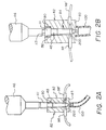
- Fig. 1 illustrates a conventional analyzer 12 utilizing the current invention. It is conventional to utilize a dispensing station 18 to collect by aspiration, a sample of biological liquid, for example, serum or plasma, from a supply comprising primary collection containers 19 in tray 20, into a disposable tip 48 mounted on aspirator probe 46. The sample liquid is subsequently dispensed onto a slide test element E held at a slide distributor 30 and obtained from a source of test elements, not shown. Control of the dispenser 40 providing probe 46 is via the mechanisms such as vertical drive 44 and carriage 42 mounted on support rods 70, all as described in, for example, US-A-4,340,390. A conventional pump 71 of any kind is used as the means for creating a partial vacuum or partial pressure within tip 48.
- a sample of biological liquid for example, serum or plasma
- a new use is made of tips 48 besides simply, the collection by aspiration, of liquid from containers 19, and then subsequent dispensing onto slide test elements E.
- Tip 48 carrying the sample liquid aspirated into it is moved, arrow 80, Fig. 1, to a test station 82 prior to placing it in holder 117 for dispensing.
- Station 82 comprises, as is more clearly shown in Figs. 2A, 2B, and 3, a scanning block that is an effective light-tight enclosure having a cavity 84 sized to receive a tip 48.
- cavity 84 comprises an upper portion 86, Fig.
- Exit port 94 is shaped generally with the shape of the exit orifice portion of tip 48, hence its conical shape for this preferred tip 48.
- An optional air tube 100 is connected to exit port 94 to reduce the potential of pumping fluid out of the tip. If the tube is also opaque, an option, then it also helps to eliminate light leakage up into the tip.
- Fiber optics 98,98' are connected to a spectrophotometer, Fig. 1, comprising a light source 110 and a detector combined into a single unit 110, which is conventional.
- station 82 is effectively light-tight as defined herein so that the light passing to the detector is at least 90% of that transmitted through tip 48 from fiber optic 98. There are several ways in which this can be achieved.
- the light leakage that occurs is corrected for by taking a blank reading (with the fiber 98 delivering no light) at the same ambient light conditions as is used when NIR and adjacent visible radiation is delivered by fiber optic 98. The blank reading is then subtracted from the sample reading and reference reading.
- the same light tightness can be achieved by extending the height of block 83 up to at least the height of the top surface 113 of upper portion 111 of tip 48, Fig. 2B.
- vent 92 Fig. 3. This vent allows the release of the increase in pressure created when a tip is inserted into station 82, so that a bubble of air is not forced into the liquid of the tip to possibly interfere with the light-scanning of the liquid.
- vent 92 prevents a vacuum being created such as could draw out of tip 48, a portion of the sample liquid which then contaminates the station 82 for subsequent tips and samples.
- locator bumps 140 can be disposed, Fig. 3, near the bottom of portion 88 above passageways 96.
- tip 48 is inserted into station 82 before insertion into holder 116. While at station 82, a beam of NIR and adjacent visible wavelengths as defined above, is passed through the tip and its liquid so that transmitted radiation is spectrophotometrically analyzed at spectrophotometer 110. The signal produced by the detector is then correlated with the concentration of target substances.
- a preferred set of target substances is those that measure sample quality, specifically those selected from the group consisting of hemoglobin, lipids, bilirubin (BR), and biliverdin (BV), as shown in the examples below.
- any target substances capable of spectrophotometric detection by its absorption spectra can be correlated and detected by this invention. More specifically, certain assays that heretofore have been conducted in slide test element E, can be conducted spectrophotometrically through the tip, as described hereinafter.
- the tip is withdrawn and inserted into holder 116 at which point the sample liquid is dispensed onto slide test element E conventionally containing one or more reagents to ascertain the concentration of an analyte in the sample liquid, as is well-known.
- the tips 48 used herein allow transmission of NIR and adjacent visible radiation, and most preferably 475 to 1200 nm, and preferably are free of labels, since any labeling is done exclusively on primary containers 19.
- Materials useful for this purpose include polypropylene and polyethylene.
- test station 82 be constructed as a solid block with only a cavity for the disposable tip and apertures for the fiber optics, or that the tip be lowered into the same. Instead, side walls of station 82 can be opened and closed, to provide a slot that allows pass-through of the tip, as shown in Figs. 4A and 5. Parts similar to those previously described bear the same reference numeral, to which the distinguishing suffix "A" has been appended.
- station 82A comprises two fixed, opposed segments 109,112 spaced a distance apart. Each segment has an opposing face, 116,116' that defines a slot 115 between them. Top surface 117 of faces 116,116' provide a guide rail and seat for upper portion 111A of tip 48A. Segment 109 has a fiber optic 98A penetrating it from a light source, not shown, whereas segment 112 has a sensor 114 in face 116 that is connected to a spectrophotometer built into or connected with segment 112.
- the opposing faces of segments 109 and 112 define slit 115 with a spacing distance that allows a disposable tip 48A to slide through, arrow 120. Those opposing faces can be spaced apart a fixed distance for the sliding of tip 48A.
- pivoting doors 130,132 are hingedly attached at 134 to opposite edges of segment 109, of sufficient width to close off slot 115 when they are pivoted, arrows 136,138 to their closed positions (not shown). (Door 132 is shown in phantom for clarity only.) To pivot the doors, preferably the pintle of hinges 134 is attached or affixed-to a rotating drive shaft (not shown), of conventional motors 136.
- doors 130 and 132 can be omitted by lengthening slot 115 so that it has an aspect ratio in the horizontal direction that is comparable to the vertical aspect ratio stated for cavity 84 above.
- a spring-biased detent 210 is preferably located in face 116, cooperating with a fixed projection 212 on opposite face 116'. Detent 210 is pushed by the tip into face 116 when it is time, after the reading, to move tip 48A out of slot 115 in the direction of arrow 120. As noted in the previous embodiment, tip 48A allows transmission of the NIR and adjacent visible wavelengths used.
- station 82B comprises plate 122B forming with faces 116B and 116'B a U-shaped slot that allows a tip 48B to slide through, arrow 120B, while supported on top surfaces 117B.
- Fiber optic 98B delivers light through stationary segment 130B, and sensor 114B in stationary face 116B delivers light to a spectrophotometer, not shown.
- segment 112B is mounted to slide on plate 122B as driven by a rack 162 and a drive pinion 164, arrow 168, thus opening or closing off the slot.
- face 116B and tip 48B occupy the space 172 within segment 112B, and wall portion 169 closes off slot 115B.
- any target substance that is analyzable spectrophotometrically using NIR and adjacent visible wavelengths can be analyzed by spectrophotometer 110 while the patient sample is in tip 48A.
- These target substances in the tip it is not necessary, and indeed the analyzer preferably skips, further assays for them when the sample is deposited onto slide test element E. This enhances greatly the total throughput of the analyzer, inasmuch as the spectrophotometric detection through the tip requires only 4 seconds for all the target substances so analyzed, compared to 4 seconds for each separate assay done on a slide test element E. "Time to result" is also drastically improved by the spectrophotometric analysis through the tip - 4 seconds for through-the-tip, compared to 5 minutes on a slide test element.
- the following is a calculation of the advantages that can be achieved on an analyzer such as is available from Johnson & Johnson Clinical Diagnostics under the trademark "VITROS 950" analyzer.
- This assumes 1) that dispensing of sample liquid onto a slide test element is the limiting step in the analysis, and that this involves 8 seconds to aspirate, 4 seconds to dispense onto a test element and load the element into the distributor of the VITROS 950 analyzer, and that all, and only, colorimetric analysis is done in the tip by this invention.
- the throughput is 300 test elements per hour. With the invention, it can be shown to be 2100 per hour, which is a 7-fold increase. If on the other hand there are only 5 colorimetric tests, and either 2 rate or 2 potentiometric tests to be conducted, then the throughput without the invention should be 420 per hour, and 1050 per hour with the invention, for a 2.5-fold increase. Still further, if the mix of seven chemistries is such that there are only 3 colorimetric and 4 potentiometric tests to run, there is no increase in throughput obtained by doing this invention (525 tests per hour in both cases.)
- Testing of such analytes in this manner while in the tip is preferably done with some kind of temperature control of the sample liquid. This need not be done only by controlling the temperature at test station 82, but can also be done by heating or cooling the sample liquid in containers 19, Fig. 1, or while the liquid is in the tips 48, and so forth, but not at station 82.
- test station 146 conventionally comprises a colorimetric or potentiometric detector, in contrast to the spectrophotometer 110 used with tips 48,48A.
- tests conducted at station 146 preferably skip those done through the tip, it is also possible to repeat at station 146 such spectrophotometric assays, to obtain a "check" on the accuracy of the latter.
- the order of testing can be reversed - that is, a portion of the sample liquid can be deposited on a test slide as described above, before doing the measurements through-the-tip at the NIR and adjacent visible wavelengths.
- Fig. 2 The apparatus of Fig. 2 was used, in which a disposable tip available from Johnson & Johnson Clinical Diagnostics, Inc., under the trademark "Vitros", heretofore known as the "Ektachem” disposable tip, was used.
- the optical fibers were 0.2 mm single fibers, connecting station 82 via the fibers 98 and 98', to a "TC 2000" dual beam, in-time spectrophotometer that uses a linear diode array detector, available from CME Telemetrix, using a tungsten-halogen light bulb light source 110 as detector 112. Diffraction gratings were used at detector 112 to allow only radiation of 580 to 1100 nm to be detected.
- the liquids tested were, first as calibrators, a randomized set of liquids comprising known amounts of hemoglobin, IntralipidTM (a fat emulsion which mimics naturally occurring chylomicrons) available from Pharmacia, Inc., and biliverdin all spiked onto a human serum matrix.
- IntralipidTM a fat emulsion which mimics naturally occurring chylomicrons
- biliverdin all spiked onto a human serum matrix.
- Hb means hemoglobin
- IL means Intralipid
- BV means biliverdin dihydrochloride
- BR means bilirubin
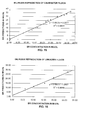
- the first set of liquids was irradiated as described above to create a calibration algorithm using conventional spectrophotometric practice, and the values of Hb detected in this measurement were plotted against the actual values, Fig. 6, to obtain a regression plot.
- a variety of calibration algorithms is useful.
- the regression correlation coefficient R 2 in the case of Fig. 6 was 0.991.
- the second set of liquids was then irradiated as described above and the predicted values plotted against their known results, Fig. 7, using the calibration algorithm derived from the first set of liquids, Fig. 6.
- the R 2 value of 0.982 was excellent. This accuracy is adequate to allow the results to be relied upon for clinical assay of Hb in unknown samples, in place of testing on a slide test element.
- Fig. 10 shows the calibration results
- Fig. 11 the prediction results with R 2 being as indicated.
- a fourth set of liquids was similarly prepared to check for prediction of the bilirubin values, and that set was comprised as follows: Sample Number BR mg/dL HB IL BV mg/dL 1 19.86 1.25 0.00 0.00 2 19.86 1.25 0.00 0.00 3 26.59 0.60 0.00 4.38 4 26.59 0.60 0.00 4.38 5 6.10 0.00 2.35 0.00 6 6.10 0.00 2.35 0.06 7 10.31 0.00 1.19 0.00 8 10.31 0.00 1.19 0.00 9 15.53 1.07 0.00 3.58 10 15.53 1.07 0.60 3.58
- Fig. 15 shows the calibration results
- Fig. 16 the prediction results with R 2 being as indicated.
- results showed excellent correlation such that the results are sufficient to use in place of testing on a slide test element, should any of these be considered a desired assay.
- the results clearly allow the biological liquid's sample quality to be ascertained so that the sample can be rejected if determined to be outside the scope of acceptable quality.
- R 2 becomes 0.988 for the calibration and 0.984 for the prediction. (The actual plots are not shown.)
- Fig. 12 is a plot demonstrating that, in fact, the first derivative of absorbence values in the NIR and adjacent visible spectra does produce sufficient separation, at useful wavelengths, of a sample having either IL, BV, or Hb components present, to allow for independent detection. That is, curve 200 is a sample having none of those components, curve 202 is a sample having only 1.79 g/l of Hb, curve 204 of a sample having only 2.38 g/l of IL, and curve 206 of a sample having only 3.95 mg/dL of BV.
- the Hb contributes primarily to the 580-605 nm region of the NIR, IL to the 896-1051 nm region and preferably 896-939 nm, and BV to the 680-750 nm region.
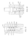
- the tip is unchanged from conventional tips, but more than a single pass of the NIR and adjacent visible radiation is achieved through the tip before the absorption spectra is received by the spectrophotometer, Fig. 13. Parts previously described are referred to by the same reference numeral, to which the distinguishing suffix "D" is appended.
- tip 48D is mounted in cavity 84D as before, for irradiation by NIR and adjacent visible radiation emanating from fiber optic 98D, to be received by fiber optic 98'D for processing.
- receiving optic 98'D is not directly opposite transmitting optic 98D, nor in position to receive the "first pass" radiation. Instead at least one, and preferably three pair(s) of mirrors (230,232; 240,242; and 250,252) are disposed to re-pass the radiation back through tip 48D as many times as there are mirrors. (Six mirrors of the three pairs retransmits the radiation through the tip six times.)
- optics 98,98' (or other versions thereof disclosed above) pass NIR and adjacent visible light through only the thickest part of the tip. Instead, the light can be transmitted through the narrower neck portion. (Parts similar to those previously described bear the same reference numeral, to which the distinguishing suffix "E" is appended.)
- illuminating fiber optic 98E is positioned in the block of station 82E so as to illuminate conical neck portion 300 of tip 48E, that has a decreasing diameter compared to diameter "d" of main body portion 224E.
- the light then transmitted through the tip to receiving fiber optic 98'E passes through much less of the sample. This is desirable if the analyte to be detected is one of high density or has a higher extinguishing coefficient for the NIR and adjacent visible wavelengths in question.
- fiber optics 98E and 98'E are moved down to the phantom position, 302, that reads through the narrowest part 304 of tip 48E.
- the sequence of steps is as follows: the steps of lowering the tip into a light-tight enclosure comprising an NIR and adjacent visible radiation emitter as shown in any of Figs. 2A, 2B, 4A, and 4B until the tip is seated therein, scanning the tip and its contents with NIR and adjacent visible radiation emitted from the emitter, and if the contents have a density above a predetermined threshold value, thereafter raising the tip within the enclosure until the emitter is positioned to scan the narrower portion of the tip.
Abstract
Description
| Sample Number | g/L Hb | g/L IL | mg/dL BV |
| 1 | 0.56 | 0.00 | 0.00 |
| 2 | 0.83 | 0.00 | 0.00 |
| 3 | 1.11 | 0.00 | 0.00 |
| 4 | 1.38 | 0.00 | 0.00 |
| 5 | 1.65 | 0.00 | 0.00 |
| 6 | 1.91 | 0.00 | 0.00 |
| 7 | 2.17 | 0.00 | 0.00 |
| 8 | 2.43 | 0.00 | 0.00 |
| 9 | 2.69 | 0.00 | 0.00 |
| 10 | 2.95 | 0.00 | 0.00 |
| 11 | 1.19 | 0.00 | 0.00 |
| 12 | 1.77 | 0.00 | 0.00 |
| 13 | 2.35 | 0.00 | 0.00 |
| 14 | 2.93 | 0.00 | 0.00 |
| 15 | 3.50 | 0.00 | 0.00 |
| 16 | 4.06 | 0.00 | 0.00 |
| 17 | 4.62 | 0.00 | 0.00 |
| 18 | 5.17 | 0.00 | 0.00 |
| 19 | 5.71 | 0.00 | 0.00 |
| 20 | 6.26 | 0.00 | 0.00 |
| 21 | 0.54 | 1.00 | 0.83 |
| 22 | 0.79 | 1.97 | 0.41 |
| 23 | 1.01 | 2.83 | 1.17 |
| 24 | 1.22 | 1.14 | 3.77 |
| 25 | 1.50 | 1.63 | 2.32 |
| 26 | 1.73 | 2.30 | 1.91 |
| 27 | 2.03 | 1.42 | 1.57 |
| 28 | 2.25 | 0.47 | 2.70 |
| 29 | 2.46 | 0.68 | 3.03 |
| 30 | 2.54 | 3.00 | 3.21 |
| 31 | 1.14 | 2.00 | 1.66 |
| 32 | 1.69 | 3.94 | 0.82 |
| 33 | 2.13 | 5.61 | 3.10 |
| 34 | 2.59 | 2.27 | 7.55 |
| 35 | 3.19 | 3.26 | 4.63 |
| 36 | 3.68 | 4.61 | 3.82 |
| 37 | 4.36 | 2.86 | 2.37 |
| 38 | 4.78 | 0.93 | 5.40 |
| 39 | 5.22 | 1.37 | 6.06 |
| 40 | 5.40 | 6.01 | 6.41 |
| Sample Number | g/L Hb | g/L IL | mg/dL BV |
| 1 | 0.34 | 2.05 | 3.40 |
| 2 | 0.50 | 2.44 | 4.06 |
| 3 | 0.66 | 2.83 | 4.69 |
| 4 | 0.80 | 3.19 | - 5.30 |
| 5 | 3.77 | 3.27 | 5.43 |
| 6 | 1.08 | 3.88 | 6.44 |
| 7 | 1.35 | 1.56 | 3.33 |
| 8 | 1.56 | 1.15 | 1.15 |
| 9 | 5.73 | 3.04 | 2.21 |
| 10 | 1.80 | 3.04 | 1.80 |
| 11 | 4.75 | 3.54 | 1.31 |
| 12 | 2.12 | 2.60 | 2.16 |
| 13 | 2.18 | 4.13 | 2.74 |
| 14 | 2.58 | 0.46 | 0.76 |
| 15 | 5.26 | 1.55 | 4.50 |
| 16 | 2.68 | 1.26 | 5.56 |
| 17 | 2.83 | 0.83 | 6.23 |
| 18 | 0.00 | 2.38 | 0.00 |
| 19 | 1.79 | 0.00 | 0.00 |
| 20 | 0.00 | 0.00 | 3.95 |
| 21 | 0 | 0 | 0 |
| C1 = 15.892 | C5 = 0.244 |
| C2 = 15.882 | C6 = 98.068 |
| C3 = 0.21 | C7 = 122.732 |
| C4 = 252.155 | C8 = 0.0685 |
| Sample Number | BR mg/dL | Hb g/L | IL gL | BV mg/dL |
| 1 | 8.33 | 0.65 | 0.00 | 0.00 |
| 2 | 8.33 | 0.65 | 0.00 | 0.00 |
| 3 | 0.00 | 1.92 | 0.00 | 0.00 |
| 4 | 0.00 | 1.92 | 0.00 | 0.00 |
| 5 | 34.79 | 0.91 | 0.00 | 0.00 |
| 6 | 34.79 | 0.91 | 0.00 | 0.00 |
| 7 | 23.41 | 1.53 | 0.00 | 0.00 |
| 8 | 23.41 | 1.53 | 0.00 | 0.00 |
| 9 | 31.49 | 0.31 | 0.00 | 0.90 |
| 10 | 31.49 | 0.31 | 0.00 | 0.90 |
| 11 | 37.33 | 1.17 | 0.00 | 1.72 |
| 12 | 37.33 | 1.17 | 0.00 | 1.72 |
| 13 | 22.15 | 0.00 | 0.93 | 0.00 |
| 14 | 22.15 | 0.00 | 0.93 | 0.00 |
| 15 | 0.00 | 0.00 | 2.15 | 0.00 |
| 16 | 0.00 | 0.00 | 2.15 | 0.00 |
| 18 | 17.02 | 0.00 | 0.00 | 8.74 |
| 19 | 17.02 | 0.00 | 0.00 | 8.74 |
| 20 | 33.31 | 0.00 | 0.00 | 1.80 |
| 21 | 33.31 | 0.00 | 0.00 | 1.80 |
| 22 | 25.02 | 0.00 | 0.00 | 5.34 |
| 23 | 25.02 | 0.00 | 0.00 | 5.34 |
| 24 | 29.13 | 0.00 | 0.00 | 3.58 |
| 25 | 29.13 | 0.00 | 0.00 | 3.58 |
| 26 | 13.59 | 0.00 | 0.00 | 7.18 |
| Sample Number | BR mg/dL | HB | IL | BV mg/dL |
| 1 | 19.86 | 1.25 | 0.00 | 0.00 |
| 2 | 19.86 | 1.25 | 0.00 | 0.00 |
| 3 | 26.59 | 0.60 | 0.00 | 4.38 |
| 4 | 26.59 | 0.60 | 0.00 | 4.38 |
| 5 | 6.10 | 0.00 | 2.35 | 0.00 |
| 6 | 6.10 | 0.00 | 2.35 | 0.06 |
| 7 | 10.31 | 0.00 | 1.19 | 0.00 |
| 8 | 10.31 | 0.00 | 1.19 | 0.00 |
| 9 | 15.53 | 1.07 | 0.00 | 3.58 |
| 10 | 15.53 | 1.07 | 0.60 | 3.58 |
Claims (22)
- A method for improving throughput in a clinical analyzer, the analyzer comprising a dispensing station and at least one test station for detecting a target substance in a patient sample, the dispensing station comprising:an aspirator probe;a tip mounted on the probe, for collecting a biological liquid from a primary collection container and for dispensing at least a portion of the collected liquid onto or into a test element; andmeans for creating a partial pressure or partial vacuum within the probe and the tip;the method comprising the steps of:a) aspirating a biological liquid into one of the tips mounted on the probe;b) while the liquid is within the tip and the tip is on the probe, detecting one or more target substances in the liquid by transmitting light of near infrared and adjacent visible radiation wavelengths through the tip and spectrophotometrically analyzing the portion of the light transmitted through the tip, by correlating the transmitted light with the concentration of one or more target substances in the liquid;c) dispensing a portion of the liquid from the tip onto a test element; andd) testing at the test station, the test element plus liquid, for target substances other than the one or more target substances;so that throughput is increased by the amount of time not required to test the one or more target substances at the test station.
- A method as defined in claim 1, wherein the liquid is selected from the group consisting of serum, plasma, urine and cerebral spinal fluid.
- A method as defined in claim 1, wherein step b) occurs after steps c) and d).
- A method as defined in claim 1, wherein the step b) comprises transmitting the light through the tip in more than one pass.
- A method as defined in claim 1, wherein the tip comprises a wide portion and a narrower portion, and the step b) comprises the step of b') transmitting light through the narrower portion of the tip.
- A method as defined in claim 5, wherein the step b') comprises moving the tip within a light-tight enclosure comprising an NIR and adjacent visible radiation emitter, so that the light transmitted by the emitter is directed through only the narrower portion.
- A method as defined in claim 6, wherein the moving of the step b') comprises the steps of lowering the tip into a light-tight enclosure comprising an NIR and adjacent visible radiation emitter until the tip is seated therein, scanning the tip and its contents with NIR and adjacent visible radiation emitted from the emitter, and if the contents have a density above a predetermined threshold value, thereafter raising the tip within the enclosure until the emitter is positioned to scan the narrower portion of the tip.
- A new use of tips used in analyzer aspirators to collect a biological liquid for dispensing into or onto a test element, comprising the steps of:a) aspirating a known quantity of the liquid from a supply of the same, into a disposable tip mounted on an analyzer aspirator;b) inserting the tip with the aspirated liquid, while still mounted on the aspirator, into a light-tight enclosed container;c) passing through the tip while enclosed, a beam of light of near infrared and adjacent visible wavelengths; andd) spectrophotometrically analyzing the portion of the light transmitted through the tip, by correlating the transmitted light with the concentration of one or more target substances in the liquid.
- A use as defined in claim 8, and further including the step of thereafter dispensing the liquid from the tip into or onto a test element containing one or more reagents effective to ascertain the concentration of an analyte in the liquid that is different from the target substance analyzed spectrophotometrically.
- A new use as defined in claim 9, wherein the target substance is selected from the group consisting of hemoglobin, lipids, bilirubin and biliverdin.
- A new use as defined in claim 8, wherein the target substance is hemoglobin.
- A new use as defined in claim 8, wherein the tip is free of any identification labels.
- A new use as defined in claim 8, and further including the step of preventing air pressurization in the enclosed container when the tip is inserted, such as could disturb the liquid level within the tip.
- A new use as defined in claim 8, wherein the liquid is selected from the group consisting of serum, plasma, whole blood, urine and cerebral spinal fluid.
- A new use as defined in claim 8, wherein the tip comprises a wide portion and a narrower portion, and the step c) comprises the step of c') transmitting light through the narrower portion of the tip.
- A new use as defined in claim 15, wherein the step c') comprises moving the tip within a light-tight enclosure comprising an NIR and adjacent visible radiation emitter, so that the light transmitted by the emitter is directed only through the narrower portion.
- A new use as defined in claim 16, wherein the moving of the step c') comprises the steps of lowering the tip into a light-tight enclosure comprising an NIR emitter until the tip is seated therein, scanning the tip and its contents with NIR and adjacent visible radiation emitted from the emitter, and if the contents have a density above a predetermined threshold value, thereafter raising the tip within the enclosure until the emitter is positioned to scan the narrower portion of the tip.
- A dispensing station for use in a clinical analyzer, comprising:an aspirator probe;a tip mounted on the probe, for collecting a biological liquid from a primary collection container and for dispensing at least a portion of the collected liquid onto or into a test element;means for creating a partial pressure or partial vacuum within the tip;characterized in that the station further includes a spectrophotometer emitting near infrared and adjacent visible radiation and generating a signal responsive to portions of the radiation absorbed by any medium the radiation passes through;a light-tight enclosure defining a cavity sized to receive the tip while mounted on the probe; andpassageways defining radiation paths to and from the enclosure from and to the spectrophotometer, the passageways being constructed to deliver and receive, respectively, the radiation for transmission through the tip when the tip is in place in the cavity, so that liquid in the tip can be irradiated by the radiation to determine concentration of target substances therein.
- A dispensing station as defined in claim 18, and further including a support for a test element constructed to receive liquid dispensed from the tip, and means for moving the probe and the tip from the enclosure to the support for liquid dispensing after the radiation is transmitted through the tip.
- A dispensing station as defined in claim 18, wherein the enclosure includes walls and a vent in one of the walls effective to prevent a vacuum from occurring when the tip is removed from the enclosure.
- A dispensing station as defined in claim 18, wherein the tip is a disposable tip.
- A dispensing station as defined in claim 18, and further including at least one pair of mirrors disposed within the cavity at a position to intercept radiation transmitted from one of the passageways through the tip in a single pass and to retransmit the radiation back through the tip for the other of the passageways to receive it.
Applications Claiming Priority (4)
| Application Number | Priority Date | Filing Date | Title |
|---|---|---|---|
| US815451 | 1985-12-31 | ||
| US81497797A | 1997-03-11 | 1997-03-11 | |
| US814977 | 1997-03-11 | ||
| US08/815,451 US5846492A (en) | 1997-03-11 | 1997-03-11 | Sample quality measurement and/or analyte measurement in the dispensing tip of an analyzer |
Publications (3)
| Publication Number | Publication Date |
|---|---|
| EP0864867A2 true EP0864867A2 (en) | 1998-09-16 |
| EP0864867A3 EP0864867A3 (en) | 1999-07-21 |
| EP0864867B1 EP0864867B1 (en) | 2003-07-16 |
Family
ID=27123908
Family Applications (1)
| Application Number | Title | Priority Date | Filing Date |
|---|---|---|---|
| EP98301734A Expired - Lifetime EP0864867B1 (en) | 1997-03-11 | 1998-03-10 | Improved analyzer throughput featuring through-the-tip analysis |
Country Status (7)
| Country | Link |
|---|---|
| EP (1) | EP0864867B1 (en) |
| JP (2) | JPH10311793A (en) |
| AT (1) | ATE245282T1 (en) |
| AU (1) | AU726717B2 (en) |
| CA (1) | CA2231305C (en) |
| DE (1) | DE69816357T2 (en) |
| ES (1) | ES2202740T3 (en) |
Cited By (4)
| Publication number | Priority date | Publication date | Assignee | Title |
|---|---|---|---|---|
| EP1186893A2 (en) * | 2000-09-11 | 2002-03-13 | Ortho-Clinical Diagnostics, Inc. | Analyzer with sample quality measurement, and method |
| CN1534298B (en) * | 2003-03-31 | 2011-12-21 | 奥索临床诊断有限公司 | Analysis instrument having fixed multifunction probe |
| CN103630524A (en) * | 2013-10-10 | 2014-03-12 | 杨建夫 | Intelligent type automatic qualitative and quantitative detection device and method for chemical substances |
| WO2019185147A1 (en) * | 2018-03-29 | 2019-10-03 | Robert Bosch Gmbh | Spectrometric measuring device and method for analyzing a medium using a spectrometric measuring device |
Families Citing this family (3)
| Publication number | Priority date | Publication date | Assignee | Title |
|---|---|---|---|---|
| US20050037505A1 (en) * | 2000-05-11 | 2005-02-17 | James Samsoondar | Spectroscopic method and apparatus for analyte measurement |
| ES2923758T3 (en) * | 2016-02-04 | 2022-09-30 | Nova Biomedical Corp | System and method for the measurement of the optical absorbance of whole blood |
| CN114753985A (en) * | 2022-04-22 | 2022-07-15 | 深圳市恒永达科技股份有限公司 | Self-adaptive air type liquid transfer pump, high-precision liquid transfer method and storage medium |
Citations (10)
| Publication number | Priority date | Publication date | Assignee | Title |
|---|---|---|---|---|
| US4318884A (en) * | 1979-12-07 | 1982-03-09 | Olympus Optical Co., Ltd. | Distributing nozzle with cooperating ionic detector |
| US4340390A (en) * | 1980-06-16 | 1982-07-20 | Eastman Kodak Company | Method and apparatus for metering biological fluids |
| US4420254A (en) * | 1980-02-19 | 1983-12-13 | Smeaton John R | Cuvet and associated apparatus and method for using same |
| US4669878A (en) * | 1984-06-29 | 1987-06-02 | American Monitor Corporation | Automatic monochromator-testing system |
| EP0404562A2 (en) * | 1989-06-21 | 1990-12-27 | University Of New Mexico | Method of and apparatus for determining the similarity of a biological analyte from a model constructed from known biological fluids |
| EP0408181A2 (en) * | 1989-07-10 | 1991-01-16 | General Atomics | An adaptor for holding a micropipette |
| US5061632A (en) * | 1989-01-31 | 1991-10-29 | Board Of Regents, The University Of Texas System | Capillary tube hemoglobinometer and oximeter |
| EP0695937A1 (en) * | 1988-12-22 | 1996-02-07 | Radiometer Medical A/S | Photometric method for the in vitro determination of a gas in a blood sample |
| WO1997007391A1 (en) * | 1995-08-18 | 1997-02-27 | Beckman Instruments, Inc. | Serum index sample probe |
| DE19535046A1 (en) * | 1995-09-21 | 1997-03-27 | Eppendorf Geraetebau Netheler | Pipetting and photometric measuring system |
Family Cites Families (14)
| Publication number | Priority date | Publication date | Assignee | Title |
|---|---|---|---|---|
| JPS5759151A (en) * | 1980-09-26 | 1982-04-09 | Olympus Optical Co Ltd | Measuring method for degree of chyle, jaundice and hemolysis in serum |
| JPH0621865B2 (en) * | 1984-02-09 | 1994-03-23 | オリンパス光学工業株式会社 | Method for measuring optical properties of sample |
| JPS61164162A (en) * | 1985-01-16 | 1986-07-24 | Shimadzu Corp | Specimen analyzing method |
| US4615360A (en) * | 1985-09-05 | 1986-10-07 | Eastman Kodak Company | Means providing separation of exterior sheath of liquid on dispensing tip |
| JPH0515082Y2 (en) * | 1986-04-30 | 1993-04-21 | ||
| JPH0827235B2 (en) * | 1987-11-17 | 1996-03-21 | 倉敷紡績株式会社 | Spectroscopic method for measuring sugar concentration |
| MX173027B (en) * | 1989-09-18 | 1994-01-28 | Univ Washington | METHOD FOR ANALYZING PROPERTIES OF A MATTER OF BIOLOGICAL ORIGIN THAT CONTAINS WATER, USING NEAR INFRARED SPECTROSCOPY |
| CA2025330C (en) * | 1989-09-18 | 2002-01-22 | David W. Osten | Characterizing biological matter in a dynamic condition using near infrared spectroscopy |
| JPH03238345A (en) * | 1990-02-16 | 1991-10-24 | Nippon Kamiparupu Kenkyusho:Kk | Residual-ink determining method |
| US5134302A (en) * | 1990-09-26 | 1992-07-28 | Futrex, Inc. | Method and means for generating synthetic spectra allowing quantitative measurement in near infrared measuring instruments |
| JP3062347B2 (en) * | 1992-04-24 | 2000-07-10 | キヤノン株式会社 | Analysis equipment |
| JP3100472B2 (en) * | 1992-09-02 | 2000-10-16 | 富士写真フイルム株式会社 | Analyzer for dry analytical element |
| AU709619B2 (en) * | 1995-02-09 | 1999-09-02 | Foss Electric A/S | A method for standardizing a plurality of spectrometers |
| US5734468A (en) * | 1995-08-18 | 1998-03-31 | Beckman Instruments, Inc. | Probe and method for determining serum indices of a serum sample |
-
1998
- 1998-03-05 CA CA002231305A patent/CA2231305C/en not_active Expired - Lifetime
- 1998-03-06 AU AU58382/98A patent/AU726717B2/en not_active Ceased
- 1998-03-10 DE DE69816357T patent/DE69816357T2/en not_active Expired - Lifetime
- 1998-03-10 JP JP10058348A patent/JPH10311793A/en not_active Withdrawn
- 1998-03-10 ES ES98301734T patent/ES2202740T3/en not_active Expired - Lifetime
- 1998-03-10 EP EP98301734A patent/EP0864867B1/en not_active Expired - Lifetime
- 1998-03-10 AT AT98301734T patent/ATE245282T1/en active
-
2007
- 2007-11-28 JP JP2007307980A patent/JP2008102149A/en active Pending
Patent Citations (10)
| Publication number | Priority date | Publication date | Assignee | Title |
|---|---|---|---|---|
| US4318884A (en) * | 1979-12-07 | 1982-03-09 | Olympus Optical Co., Ltd. | Distributing nozzle with cooperating ionic detector |
| US4420254A (en) * | 1980-02-19 | 1983-12-13 | Smeaton John R | Cuvet and associated apparatus and method for using same |
| US4340390A (en) * | 1980-06-16 | 1982-07-20 | Eastman Kodak Company | Method and apparatus for metering biological fluids |
| US4669878A (en) * | 1984-06-29 | 1987-06-02 | American Monitor Corporation | Automatic monochromator-testing system |
| EP0695937A1 (en) * | 1988-12-22 | 1996-02-07 | Radiometer Medical A/S | Photometric method for the in vitro determination of a gas in a blood sample |
| US5061632A (en) * | 1989-01-31 | 1991-10-29 | Board Of Regents, The University Of Texas System | Capillary tube hemoglobinometer and oximeter |
| EP0404562A2 (en) * | 1989-06-21 | 1990-12-27 | University Of New Mexico | Method of and apparatus for determining the similarity of a biological analyte from a model constructed from known biological fluids |
| EP0408181A2 (en) * | 1989-07-10 | 1991-01-16 | General Atomics | An adaptor for holding a micropipette |
| WO1997007391A1 (en) * | 1995-08-18 | 1997-02-27 | Beckman Instruments, Inc. | Serum index sample probe |
| DE19535046A1 (en) * | 1995-09-21 | 1997-03-27 | Eppendorf Geraetebau Netheler | Pipetting and photometric measuring system |
Cited By (6)
| Publication number | Priority date | Publication date | Assignee | Title |
|---|---|---|---|---|
| EP1186893A2 (en) * | 2000-09-11 | 2002-03-13 | Ortho-Clinical Diagnostics, Inc. | Analyzer with sample quality measurement, and method |
| EP1186893A3 (en) * | 2000-09-11 | 2004-03-24 | Ortho-Clinical Diagnostics, Inc. | Analyzer with sample quality measurement, and method |
| CN1534298B (en) * | 2003-03-31 | 2011-12-21 | 奥索临床诊断有限公司 | Analysis instrument having fixed multifunction probe |
| CN103630524A (en) * | 2013-10-10 | 2014-03-12 | 杨建夫 | Intelligent type automatic qualitative and quantitative detection device and method for chemical substances |
| CN103630524B (en) * | 2013-10-10 | 2016-06-08 | 杨建夫 | The detection device of the chemical substance quantitative and qualitative analysis of intelligent type automatic |
| WO2019185147A1 (en) * | 2018-03-29 | 2019-10-03 | Robert Bosch Gmbh | Spectrometric measuring device and method for analyzing a medium using a spectrometric measuring device |
Also Published As
| Publication number | Publication date |
|---|---|
| AU5838298A (en) | 1998-09-17 |
| ES2202740T3 (en) | 2004-04-01 |
| DE69816357D1 (en) | 2003-08-21 |
| EP0864867B1 (en) | 2003-07-16 |
| JP2008102149A (en) | 2008-05-01 |
| AU726717B2 (en) | 2000-11-16 |
| CA2231305C (en) | 2007-03-20 |
| DE69816357T2 (en) | 2004-09-09 |
| EP0864867A3 (en) | 1999-07-21 |
| CA2231305A1 (en) | 1998-09-11 |
| ATE245282T1 (en) | 2003-08-15 |
| JPH10311793A (en) | 1998-11-24 |
Similar Documents
| Publication | Publication Date | Title |
|---|---|---|
| US6013528A (en) | Analyzer throughput featuring through-the-tip analysis | |
| US5846492A (en) | Sample quality measurement and/or analyte measurement in the dispensing tip of an analyzer | |
| JP3994143B2 (en) | Pre-test differentiation method and apparatus for rapid spectrophotometry of specimens for hematology analyzers | |
| US6841132B2 (en) | Sample tab | |
| EP0967954B1 (en) | APPARATUS FOR determining the concentration of INTERFERENTS IN PLASMA | |
| US7688448B2 (en) | Through-container optical evaluation system | |
| US6353471B1 (en) | Method and apparatus for non-destructive screening of specimen integrity | |
| EP1586888A2 (en) | Spectroscopic method and apparatus for analyte measurement | |
| EP2016390B1 (en) | A method and a system for quantitative hemoglobin determination | |
| JP3547894B2 (en) | Method and apparatus for determining blood sedimentation velocity | |
| US20050054112A1 (en) | Analyzer with sample quality measurement, and method | |
| US6522398B2 (en) | Apparatus for measuring hematocrit | |
| CA2469099C (en) | Spectroscopic method and apparatus for total hemoglobin measurement | |
| JP2008102149A (en) | Method for improving analyzer throughput, method for using tip of analyzer, and dispensing station of analyzer | |
| WO1997008555A1 (en) | System and methods for performing rotor assays | |
| JP4638546B2 (en) | Method for improving throughput in a clinical analyzer | |
| CN111965173A (en) | Urine detector and detection method thereof | |
| US6995835B2 (en) | Method and apparatus for measuring analytes in blood bags | |
| JP2002506981A (en) | Method and apparatus for measuring protein | |
| EP1870697A2 (en) | Solid control and/or calibration element for use in a diagnostic analyzer | |
| JPS61164162A (en) | Specimen analyzing method |
Legal Events
| Date | Code | Title | Description |
|---|---|---|---|
| PUAI | Public reference made under article 153(3) epc to a published international application that has entered the european phase |
Free format text: ORIGINAL CODE: 0009012 |
|
| AK | Designated contracting states |
Kind code of ref document: A2 Designated state(s): AT BE CH DE DK ES FI FR GB GR IE IT LI LU MC NL PT SE |
|
| AX | Request for extension of the european patent |
Free format text: AL;LT;LV;MK;RO;SI |
|
| PUAL | Search report despatched |
Free format text: ORIGINAL CODE: 0009013 |
|
| AK | Designated contracting states |
Kind code of ref document: A3 Designated state(s): AT BE CH DE DK ES FI FR GB GR IE IT LI LU MC NL PT SE |
|
| AX | Request for extension of the european patent |
Free format text: AL;LT;LV;MK;RO;SI |
|
| RIC1 | Information provided on ipc code assigned before grant |
Free format text: 6G 01N 35/10 A, 6G 01N 21/05 B, 6G 01N 21/35 B |
|
| 17P | Request for examination filed |
Effective date: 19991228 |
|
| AKX | Designation fees paid |
Free format text: AT BE CH DE DK ES FI FR GB GR IE IT LI LU MC NL PT SE |
|
| AXX | Extension fees paid |
Free format text: SI PAYMENT 19991228 |
|
| 17Q | First examination report despatched |
Effective date: 20010404 |
|
| GRAH | Despatch of communication of intention to grant a patent |
Free format text: ORIGINAL CODE: EPIDOS IGRA |
|
| GRAH | Despatch of communication of intention to grant a patent |
Free format text: ORIGINAL CODE: EPIDOS IGRA |
|
| GRAA | (expected) grant |
Free format text: ORIGINAL CODE: 0009210 |
|
| AK | Designated contracting states |
Designated state(s): AT BE CH DE DK ES FI FR GB GR IE IT LI LU MC NL PT SE |
|
| AX | Request for extension of the european patent |
Extension state: SI |
|
| PG25 | Lapsed in a contracting state [announced via postgrant information from national office to epo] |
Ref country code: NL Free format text: LAPSE BECAUSE OF FAILURE TO SUBMIT A TRANSLATION OF THE DESCRIPTION OR TO PAY THE FEE WITHIN THE PRESCRIBED TIME-LIMIT Effective date: 20030716 Ref country code: BE Free format text: LAPSE BECAUSE OF FAILURE TO SUBMIT A TRANSLATION OF THE DESCRIPTION OR TO PAY THE FEE WITHIN THE PRESCRIBED TIME-LIMIT Effective date: 20030716 |
|
| REG | Reference to a national code |
Ref country code: GB Ref legal event code: FG4D |
|
| REG | Reference to a national code |
Ref country code: CH Ref legal event code: EP |
|
| REG | Reference to a national code |
Ref country code: IE Ref legal event code: FG4D |
|
| REF | Corresponds to: |
Ref document number: 69816357 Country of ref document: DE Date of ref document: 20030821 Kind code of ref document: P |
|
| PG25 | Lapsed in a contracting state [announced via postgrant information from national office to epo] |
Ref country code: SE Free format text: LAPSE BECAUSE OF FAILURE TO SUBMIT A TRANSLATION OF THE DESCRIPTION OR TO PAY THE FEE WITHIN THE PRESCRIBED TIME-LIMIT Effective date: 20031016 Ref country code: GR Free format text: LAPSE BECAUSE OF FAILURE TO SUBMIT A TRANSLATION OF THE DESCRIPTION OR TO PAY THE FEE WITHIN THE PRESCRIBED TIME-LIMIT Effective date: 20031016 Ref country code: DK Free format text: LAPSE BECAUSE OF FAILURE TO SUBMIT A TRANSLATION OF THE DESCRIPTION OR TO PAY THE FEE WITHIN THE PRESCRIBED TIME-LIMIT Effective date: 20031016 |
|
| REG | Reference to a national code |
Ref country code: CH Ref legal event code: NV Representative=s name: DR. LUSUARDI AG |
|
| NLV1 | Nl: lapsed or annulled due to failure to fulfill the requirements of art. 29p and 29m of the patents act | ||
| PG25 | Lapsed in a contracting state [announced via postgrant information from national office to epo] |
Ref country code: PT Free format text: LAPSE BECAUSE OF FAILURE TO SUBMIT A TRANSLATION OF THE DESCRIPTION OR TO PAY THE FEE WITHIN THE PRESCRIBED TIME-LIMIT Effective date: 20031216 |
|
| PG25 | Lapsed in a contracting state [announced via postgrant information from national office to epo] |
Ref country code: LU Free format text: LAPSE BECAUSE OF NON-PAYMENT OF DUE FEES Effective date: 20040310 |
|
| PG25 | Lapsed in a contracting state [announced via postgrant information from national office to epo] |
Ref country code: MC Free format text: LAPSE BECAUSE OF NON-PAYMENT OF DUE FEES Effective date: 20040331 |
|
| REG | Reference to a national code |
Ref country code: ES Ref legal event code: FG2A Ref document number: 2202740 Country of ref document: ES Kind code of ref document: T3 |
|
| ET | Fr: translation filed | ||
| PLBE | No opposition filed within time limit |
Free format text: ORIGINAL CODE: 0009261 |
|
| STAA | Information on the status of an ep patent application or granted ep patent |
Free format text: STATUS: NO OPPOSITION FILED WITHIN TIME LIMIT |
|
| 26N | No opposition filed |
Effective date: 20040419 |
|
| REG | Reference to a national code |
Ref country code: CH Ref legal event code: PFA Owner name: ORTHO-CLINICAL DIAGNOSTICS, INC. Free format text: ORTHO-CLINICAL DIAGNOSTICS, INC.#100 INDIGO CREEK DRIVE#ROCHESTER, NY 14626-5101 (US) -TRANSFER TO- ORTHO-CLINICAL DIAGNOSTICS, INC.#100 INDIGO CREEK DRIVE#ROCHESTER, NY 14626-5101 (US) |
|
| PGFP | Annual fee paid to national office [announced via postgrant information from national office to epo] |
Ref country code: AT Payment date: 20110228 Year of fee payment: 14 Ref country code: IT Payment date: 20110321 Year of fee payment: 14 |
|
| REG | Reference to a national code |
Ref country code: AT Ref legal event code: MM01 Ref document number: 245282 Country of ref document: AT Kind code of ref document: T Effective date: 20120310 |
|
| PG25 | Lapsed in a contracting state [announced via postgrant information from national office to epo] |
Ref country code: AT Free format text: LAPSE BECAUSE OF NON-PAYMENT OF DUE FEES Effective date: 20120310 |
|
| PG25 | Lapsed in a contracting state [announced via postgrant information from national office to epo] |
Ref country code: IT Free format text: LAPSE BECAUSE OF NON-PAYMENT OF DUE FEES Effective date: 20120310 |
|
| PGFP | Annual fee paid to national office [announced via postgrant information from national office to epo] |
Ref country code: IE Payment date: 20140311 Year of fee payment: 17 Ref country code: FI Payment date: 20140311 Year of fee payment: 17 |
|
| PGFP | Annual fee paid to national office [announced via postgrant information from national office to epo] |
Ref country code: ES Payment date: 20140211 Year of fee payment: 17 |
|
| PG25 | Lapsed in a contracting state [announced via postgrant information from national office to epo] |
Ref country code: FI Free format text: LAPSE BECAUSE OF NON-PAYMENT OF DUE FEES Effective date: 20150310 |
|
| REG | Reference to a national code |
Ref country code: IE Ref legal event code: MM4A |
|
| PG25 | Lapsed in a contracting state [announced via postgrant information from national office to epo] |
Ref country code: IE Free format text: LAPSE BECAUSE OF NON-PAYMENT OF DUE FEES Effective date: 20150310 |
|
| REG | Reference to a national code |
Ref country code: FR Ref legal event code: PLFP Year of fee payment: 19 |
|
| REG | Reference to a national code |
Ref country code: ES Ref legal event code: FD2A Effective date: 20160427 |
|
| PG25 | Lapsed in a contracting state [announced via postgrant information from national office to epo] |
Ref country code: ES Free format text: LAPSE BECAUSE OF NON-PAYMENT OF DUE FEES Effective date: 20150311 |
|
| REG | Reference to a national code |
Ref country code: FR Ref legal event code: PLFP Year of fee payment: 20 |
|
| PGFP | Annual fee paid to national office [announced via postgrant information from national office to epo] |
Ref country code: DE Payment date: 20170307 Year of fee payment: 20 Ref country code: FR Payment date: 20170213 Year of fee payment: 20 Ref country code: CH Payment date: 20170314 Year of fee payment: 20 |
|
| PGFP | Annual fee paid to national office [announced via postgrant information from national office to epo] |
Ref country code: GB Payment date: 20170308 Year of fee payment: 20 |
|
| REG | Reference to a national code |
Ref country code: DE Ref legal event code: R071 Ref document number: 69816357 Country of ref document: DE |
|
| REG | Reference to a national code |
Ref country code: CH Ref legal event code: PL |
|
| REG | Reference to a national code |
Ref country code: GB Ref legal event code: PE20 Expiry date: 20180309 |
|
| PG25 | Lapsed in a contracting state [announced via postgrant information from national office to epo] |
Ref country code: GB Free format text: LAPSE BECAUSE OF EXPIRATION OF PROTECTION Effective date: 20180309 |