EP0864302A2 - Articulated expandable intraluminal stent - Google Patents
Articulated expandable intraluminal stent Download PDFInfo
- Publication number
- EP0864302A2 EP0864302A2 EP98301708A EP98301708A EP0864302A2 EP 0864302 A2 EP0864302 A2 EP 0864302A2 EP 98301708 A EP98301708 A EP 98301708A EP 98301708 A EP98301708 A EP 98301708A EP 0864302 A2 EP0864302 A2 EP 0864302A2
- Authority
- EP
- European Patent Office
- Prior art keywords
- stent
- body passageway
- expandable
- graft
- prosthesis
- Prior art date
- Legal status (The legal status is an assumption and is not a legal conclusion. Google has not performed a legal analysis and makes no representation as to the accuracy of the status listed.)
- Withdrawn
Links
Images


Classifications
-
- A—HUMAN NECESSITIES
- A61—MEDICAL OR VETERINARY SCIENCE; HYGIENE
- A61F—FILTERS IMPLANTABLE INTO BLOOD VESSELS; PROSTHESES; DEVICES PROVIDING PATENCY TO, OR PREVENTING COLLAPSING OF, TUBULAR STRUCTURES OF THE BODY, e.g. STENTS; ORTHOPAEDIC, NURSING OR CONTRACEPTIVE DEVICES; FOMENTATION; TREATMENT OR PROTECTION OF EYES OR EARS; BANDAGES, DRESSINGS OR ABSORBENT PADS; FIRST-AID KITS
- A61F2/00—Filters implantable into blood vessels; Prostheses, i.e. artificial substitutes or replacements for parts of the body; Appliances for connecting them with the body; Devices providing patency to, or preventing collapsing of, tubular structures of the body, e.g. stents
- A61F2/82—Devices providing patency to, or preventing collapsing of, tubular structures of the body, e.g. stents
- A61F2/86—Stents in a form characterised by the wire-like elements; Stents in the form characterised by a net-like or mesh-like structure
- A61F2/90—Stents in a form characterised by the wire-like elements; Stents in the form characterised by a net-like or mesh-like structure characterised by a net-like or mesh-like structure
- A61F2/91—Stents in a form characterised by the wire-like elements; Stents in the form characterised by a net-like or mesh-like structure characterised by a net-like or mesh-like structure made from perforated sheet material or tubes, e.g. perforated by laser cuts or etched holes
- A61F2/915—Stents in a form characterised by the wire-like elements; Stents in the form characterised by a net-like or mesh-like structure characterised by a net-like or mesh-like structure made from perforated sheet material or tubes, e.g. perforated by laser cuts or etched holes with bands having a meander structure, adjacent bands being connected to each other
-
- A—HUMAN NECESSITIES
- A61—MEDICAL OR VETERINARY SCIENCE; HYGIENE
- A61F—FILTERS IMPLANTABLE INTO BLOOD VESSELS; PROSTHESES; DEVICES PROVIDING PATENCY TO, OR PREVENTING COLLAPSING OF, TUBULAR STRUCTURES OF THE BODY, e.g. STENTS; ORTHOPAEDIC, NURSING OR CONTRACEPTIVE DEVICES; FOMENTATION; TREATMENT OR PROTECTION OF EYES OR EARS; BANDAGES, DRESSINGS OR ABSORBENT PADS; FIRST-AID KITS
- A61F2/00—Filters implantable into blood vessels; Prostheses, i.e. artificial substitutes or replacements for parts of the body; Appliances for connecting them with the body; Devices providing patency to, or preventing collapsing of, tubular structures of the body, e.g. stents
- A61F2/02—Prostheses implantable into the body
- A61F2/04—Hollow or tubular parts of organs, e.g. bladders, tracheae, bronchi or bile ducts
- A61F2/06—Blood vessels
- A61F2/07—Stent-grafts
-
- A—HUMAN NECESSITIES
- A61—MEDICAL OR VETERINARY SCIENCE; HYGIENE
- A61F—FILTERS IMPLANTABLE INTO BLOOD VESSELS; PROSTHESES; DEVICES PROVIDING PATENCY TO, OR PREVENTING COLLAPSING OF, TUBULAR STRUCTURES OF THE BODY, e.g. STENTS; ORTHOPAEDIC, NURSING OR CONTRACEPTIVE DEVICES; FOMENTATION; TREATMENT OR PROTECTION OF EYES OR EARS; BANDAGES, DRESSINGS OR ABSORBENT PADS; FIRST-AID KITS
- A61F2/00—Filters implantable into blood vessels; Prostheses, i.e. artificial substitutes or replacements for parts of the body; Appliances for connecting them with the body; Devices providing patency to, or preventing collapsing of, tubular structures of the body, e.g. stents
- A61F2/82—Devices providing patency to, or preventing collapsing of, tubular structures of the body, e.g. stents
- A61F2/86—Stents in a form characterised by the wire-like elements; Stents in the form characterised by a net-like or mesh-like structure
- A61F2/89—Stents in a form characterised by the wire-like elements; Stents in the form characterised by a net-like or mesh-like structure the wire-like elements comprising two or more adjacent rings flexibly connected by separate members
-
- A—HUMAN NECESSITIES
- A61—MEDICAL OR VETERINARY SCIENCE; HYGIENE
- A61F—FILTERS IMPLANTABLE INTO BLOOD VESSELS; PROSTHESES; DEVICES PROVIDING PATENCY TO, OR PREVENTING COLLAPSING OF, TUBULAR STRUCTURES OF THE BODY, e.g. STENTS; ORTHOPAEDIC, NURSING OR CONTRACEPTIVE DEVICES; FOMENTATION; TREATMENT OR PROTECTION OF EYES OR EARS; BANDAGES, DRESSINGS OR ABSORBENT PADS; FIRST-AID KITS
- A61F2/00—Filters implantable into blood vessels; Prostheses, i.e. artificial substitutes or replacements for parts of the body; Appliances for connecting them with the body; Devices providing patency to, or preventing collapsing of, tubular structures of the body, e.g. stents
- A61F2/95—Instruments specially adapted for placement or removal of stents or stent-grafts
- A61F2/958—Inflatable balloons for placing stents or stent-grafts
-
- A—HUMAN NECESSITIES
- A61—MEDICAL OR VETERINARY SCIENCE; HYGIENE
- A61F—FILTERS IMPLANTABLE INTO BLOOD VESSELS; PROSTHESES; DEVICES PROVIDING PATENCY TO, OR PREVENTING COLLAPSING OF, TUBULAR STRUCTURES OF THE BODY, e.g. STENTS; ORTHOPAEDIC, NURSING OR CONTRACEPTIVE DEVICES; FOMENTATION; TREATMENT OR PROTECTION OF EYES OR EARS; BANDAGES, DRESSINGS OR ABSORBENT PADS; FIRST-AID KITS
- A61F2/00—Filters implantable into blood vessels; Prostheses, i.e. artificial substitutes or replacements for parts of the body; Appliances for connecting them with the body; Devices providing patency to, or preventing collapsing of, tubular structures of the body, e.g. stents
- A61F2/02—Prostheses implantable into the body
- A61F2/30—Joints
- A61F2002/30001—Additional features of subject-matter classified in A61F2/28, A61F2/30 and subgroups thereof
- A61F2002/30108—Shapes
- A61F2002/3011—Cross-sections or two-dimensional shapes
- A61F2002/30138—Convex polygonal shapes
- A61F2002/30143—Convex polygonal shapes hexagonal
-
- A—HUMAN NECESSITIES
- A61—MEDICAL OR VETERINARY SCIENCE; HYGIENE
- A61F—FILTERS IMPLANTABLE INTO BLOOD VESSELS; PROSTHESES; DEVICES PROVIDING PATENCY TO, OR PREVENTING COLLAPSING OF, TUBULAR STRUCTURES OF THE BODY, e.g. STENTS; ORTHOPAEDIC, NURSING OR CONTRACEPTIVE DEVICES; FOMENTATION; TREATMENT OR PROTECTION OF EYES OR EARS; BANDAGES, DRESSINGS OR ABSORBENT PADS; FIRST-AID KITS
- A61F2/00—Filters implantable into blood vessels; Prostheses, i.e. artificial substitutes or replacements for parts of the body; Appliances for connecting them with the body; Devices providing patency to, or preventing collapsing of, tubular structures of the body, e.g. stents
- A61F2/02—Prostheses implantable into the body
- A61F2/30—Joints
- A61F2002/30001—Additional features of subject-matter classified in A61F2/28, A61F2/30 and subgroups thereof
- A61F2002/30108—Shapes
- A61F2002/3011—Cross-sections or two-dimensional shapes
- A61F2002/30138—Convex polygonal shapes
- A61F2002/30153—Convex polygonal shapes rectangular
-
- A—HUMAN NECESSITIES
- A61—MEDICAL OR VETERINARY SCIENCE; HYGIENE
- A61F—FILTERS IMPLANTABLE INTO BLOOD VESSELS; PROSTHESES; DEVICES PROVIDING PATENCY TO, OR PREVENTING COLLAPSING OF, TUBULAR STRUCTURES OF THE BODY, e.g. STENTS; ORTHOPAEDIC, NURSING OR CONTRACEPTIVE DEVICES; FOMENTATION; TREATMENT OR PROTECTION OF EYES OR EARS; BANDAGES, DRESSINGS OR ABSORBENT PADS; FIRST-AID KITS
- A61F2/00—Filters implantable into blood vessels; Prostheses, i.e. artificial substitutes or replacements for parts of the body; Appliances for connecting them with the body; Devices providing patency to, or preventing collapsing of, tubular structures of the body, e.g. stents
- A61F2/02—Prostheses implantable into the body
- A61F2/30—Joints
- A61F2002/30001—Additional features of subject-matter classified in A61F2/28, A61F2/30 and subgroups thereof
- A61F2002/30108—Shapes
- A61F2002/3011—Cross-sections or two-dimensional shapes
- A61F2002/30138—Convex polygonal shapes
- A61F2002/30154—Convex polygonal shapes square
-
- A—HUMAN NECESSITIES
- A61—MEDICAL OR VETERINARY SCIENCE; HYGIENE
- A61F—FILTERS IMPLANTABLE INTO BLOOD VESSELS; PROSTHESES; DEVICES PROVIDING PATENCY TO, OR PREVENTING COLLAPSING OF, TUBULAR STRUCTURES OF THE BODY, e.g. STENTS; ORTHOPAEDIC, NURSING OR CONTRACEPTIVE DEVICES; FOMENTATION; TREATMENT OR PROTECTION OF EYES OR EARS; BANDAGES, DRESSINGS OR ABSORBENT PADS; FIRST-AID KITS
- A61F2/00—Filters implantable into blood vessels; Prostheses, i.e. artificial substitutes or replacements for parts of the body; Appliances for connecting them with the body; Devices providing patency to, or preventing collapsing of, tubular structures of the body, e.g. stents
- A61F2/02—Prostheses implantable into the body
- A61F2/30—Joints
- A61F2002/30001—Additional features of subject-matter classified in A61F2/28, A61F2/30 and subgroups thereof
- A61F2002/30108—Shapes
- A61F2002/3011—Cross-sections or two-dimensional shapes
- A61F2002/30138—Convex polygonal shapes
- A61F2002/30156—Convex polygonal shapes triangular
-
- A—HUMAN NECESSITIES
- A61—MEDICAL OR VETERINARY SCIENCE; HYGIENE
- A61F—FILTERS IMPLANTABLE INTO BLOOD VESSELS; PROSTHESES; DEVICES PROVIDING PATENCY TO, OR PREVENTING COLLAPSING OF, TUBULAR STRUCTURES OF THE BODY, e.g. STENTS; ORTHOPAEDIC, NURSING OR CONTRACEPTIVE DEVICES; FOMENTATION; TREATMENT OR PROTECTION OF EYES OR EARS; BANDAGES, DRESSINGS OR ABSORBENT PADS; FIRST-AID KITS
- A61F2/00—Filters implantable into blood vessels; Prostheses, i.e. artificial substitutes or replacements for parts of the body; Appliances for connecting them with the body; Devices providing patency to, or preventing collapsing of, tubular structures of the body, e.g. stents
- A61F2/82—Devices providing patency to, or preventing collapsing of, tubular structures of the body, e.g. stents
- A61F2002/825—Devices providing patency to, or preventing collapsing of, tubular structures of the body, e.g. stents having longitudinal struts
-
- A—HUMAN NECESSITIES
- A61—MEDICAL OR VETERINARY SCIENCE; HYGIENE
- A61F—FILTERS IMPLANTABLE INTO BLOOD VESSELS; PROSTHESES; DEVICES PROVIDING PATENCY TO, OR PREVENTING COLLAPSING OF, TUBULAR STRUCTURES OF THE BODY, e.g. STENTS; ORTHOPAEDIC, NURSING OR CONTRACEPTIVE DEVICES; FOMENTATION; TREATMENT OR PROTECTION OF EYES OR EARS; BANDAGES, DRESSINGS OR ABSORBENT PADS; FIRST-AID KITS
- A61F2/00—Filters implantable into blood vessels; Prostheses, i.e. artificial substitutes or replacements for parts of the body; Appliances for connecting them with the body; Devices providing patency to, or preventing collapsing of, tubular structures of the body, e.g. stents
- A61F2/82—Devices providing patency to, or preventing collapsing of, tubular structures of the body, e.g. stents
- A61F2002/828—Means for connecting a plurality of stents allowing flexibility of the whole structure
-
- A—HUMAN NECESSITIES
- A61—MEDICAL OR VETERINARY SCIENCE; HYGIENE
- A61F—FILTERS IMPLANTABLE INTO BLOOD VESSELS; PROSTHESES; DEVICES PROVIDING PATENCY TO, OR PREVENTING COLLAPSING OF, TUBULAR STRUCTURES OF THE BODY, e.g. STENTS; ORTHOPAEDIC, NURSING OR CONTRACEPTIVE DEVICES; FOMENTATION; TREATMENT OR PROTECTION OF EYES OR EARS; BANDAGES, DRESSINGS OR ABSORBENT PADS; FIRST-AID KITS
- A61F2/00—Filters implantable into blood vessels; Prostheses, i.e. artificial substitutes or replacements for parts of the body; Appliances for connecting them with the body; Devices providing patency to, or preventing collapsing of, tubular structures of the body, e.g. stents
- A61F2/82—Devices providing patency to, or preventing collapsing of, tubular structures of the body, e.g. stents
- A61F2/86—Stents in a form characterised by the wire-like elements; Stents in the form characterised by a net-like or mesh-like structure
- A61F2/90—Stents in a form characterised by the wire-like elements; Stents in the form characterised by a net-like or mesh-like structure characterised by a net-like or mesh-like structure
- A61F2/91—Stents in a form characterised by the wire-like elements; Stents in the form characterised by a net-like or mesh-like structure characterised by a net-like or mesh-like structure made from perforated sheet material or tubes, e.g. perforated by laser cuts or etched holes
- A61F2/915—Stents in a form characterised by the wire-like elements; Stents in the form characterised by a net-like or mesh-like structure characterised by a net-like or mesh-like structure made from perforated sheet material or tubes, e.g. perforated by laser cuts or etched holes with bands having a meander structure, adjacent bands being connected to each other
- A61F2002/91525—Stents in a form characterised by the wire-like elements; Stents in the form characterised by a net-like or mesh-like structure characterised by a net-like or mesh-like structure made from perforated sheet material or tubes, e.g. perforated by laser cuts or etched holes with bands having a meander structure, adjacent bands being connected to each other within the whole structure different bands showing different meander characteristics, e.g. frequency or amplitude
-
- A—HUMAN NECESSITIES
- A61—MEDICAL OR VETERINARY SCIENCE; HYGIENE
- A61F—FILTERS IMPLANTABLE INTO BLOOD VESSELS; PROSTHESES; DEVICES PROVIDING PATENCY TO, OR PREVENTING COLLAPSING OF, TUBULAR STRUCTURES OF THE BODY, e.g. STENTS; ORTHOPAEDIC, NURSING OR CONTRACEPTIVE DEVICES; FOMENTATION; TREATMENT OR PROTECTION OF EYES OR EARS; BANDAGES, DRESSINGS OR ABSORBENT PADS; FIRST-AID KITS
- A61F2/00—Filters implantable into blood vessels; Prostheses, i.e. artificial substitutes or replacements for parts of the body; Appliances for connecting them with the body; Devices providing patency to, or preventing collapsing of, tubular structures of the body, e.g. stents
- A61F2/82—Devices providing patency to, or preventing collapsing of, tubular structures of the body, e.g. stents
- A61F2/86—Stents in a form characterised by the wire-like elements; Stents in the form characterised by a net-like or mesh-like structure
- A61F2/90—Stents in a form characterised by the wire-like elements; Stents in the form characterised by a net-like or mesh-like structure characterised by a net-like or mesh-like structure
- A61F2/91—Stents in a form characterised by the wire-like elements; Stents in the form characterised by a net-like or mesh-like structure characterised by a net-like or mesh-like structure made from perforated sheet material or tubes, e.g. perforated by laser cuts or etched holes
- A61F2/915—Stents in a form characterised by the wire-like elements; Stents in the form characterised by a net-like or mesh-like structure characterised by a net-like or mesh-like structure made from perforated sheet material or tubes, e.g. perforated by laser cuts or etched holes with bands having a meander structure, adjacent bands being connected to each other
- A61F2002/91533—Stents in a form characterised by the wire-like elements; Stents in the form characterised by a net-like or mesh-like structure characterised by a net-like or mesh-like structure made from perforated sheet material or tubes, e.g. perforated by laser cuts or etched holes with bands having a meander structure, adjacent bands being connected to each other characterised by the phase between adjacent bands
- A61F2002/91541—Adjacent bands are arranged out of phase
-
- A—HUMAN NECESSITIES
- A61—MEDICAL OR VETERINARY SCIENCE; HYGIENE
- A61F—FILTERS IMPLANTABLE INTO BLOOD VESSELS; PROSTHESES; DEVICES PROVIDING PATENCY TO, OR PREVENTING COLLAPSING OF, TUBULAR STRUCTURES OF THE BODY, e.g. STENTS; ORTHOPAEDIC, NURSING OR CONTRACEPTIVE DEVICES; FOMENTATION; TREATMENT OR PROTECTION OF EYES OR EARS; BANDAGES, DRESSINGS OR ABSORBENT PADS; FIRST-AID KITS
- A61F2/00—Filters implantable into blood vessels; Prostheses, i.e. artificial substitutes or replacements for parts of the body; Appliances for connecting them with the body; Devices providing patency to, or preventing collapsing of, tubular structures of the body, e.g. stents
- A61F2/82—Devices providing patency to, or preventing collapsing of, tubular structures of the body, e.g. stents
- A61F2/86—Stents in a form characterised by the wire-like elements; Stents in the form characterised by a net-like or mesh-like structure
- A61F2/90—Stents in a form characterised by the wire-like elements; Stents in the form characterised by a net-like or mesh-like structure characterised by a net-like or mesh-like structure
- A61F2/91—Stents in a form characterised by the wire-like elements; Stents in the form characterised by a net-like or mesh-like structure characterised by a net-like or mesh-like structure made from perforated sheet material or tubes, e.g. perforated by laser cuts or etched holes
- A61F2/915—Stents in a form characterised by the wire-like elements; Stents in the form characterised by a net-like or mesh-like structure characterised by a net-like or mesh-like structure made from perforated sheet material or tubes, e.g. perforated by laser cuts or etched holes with bands having a meander structure, adjacent bands being connected to each other
- A61F2002/9155—Adjacent bands being connected to each other
- A61F2002/91558—Adjacent bands being connected to each other connected peak to peak
-
- A—HUMAN NECESSITIES
- A61—MEDICAL OR VETERINARY SCIENCE; HYGIENE
- A61F—FILTERS IMPLANTABLE INTO BLOOD VESSELS; PROSTHESES; DEVICES PROVIDING PATENCY TO, OR PREVENTING COLLAPSING OF, TUBULAR STRUCTURES OF THE BODY, e.g. STENTS; ORTHOPAEDIC, NURSING OR CONTRACEPTIVE DEVICES; FOMENTATION; TREATMENT OR PROTECTION OF EYES OR EARS; BANDAGES, DRESSINGS OR ABSORBENT PADS; FIRST-AID KITS
- A61F2220/00—Fixations or connections for prostheses classified in groups A61F2/00 - A61F2/26 or A61F2/82 or A61F9/00 or A61F11/00 or subgroups thereof
- A61F2220/0025—Connections or couplings between prosthetic parts, e.g. between modular parts; Connecting elements
- A61F2220/005—Connections or couplings between prosthetic parts, e.g. between modular parts; Connecting elements using adhesives
-
- A—HUMAN NECESSITIES
- A61—MEDICAL OR VETERINARY SCIENCE; HYGIENE
- A61F—FILTERS IMPLANTABLE INTO BLOOD VESSELS; PROSTHESES; DEVICES PROVIDING PATENCY TO, OR PREVENTING COLLAPSING OF, TUBULAR STRUCTURES OF THE BODY, e.g. STENTS; ORTHOPAEDIC, NURSING OR CONTRACEPTIVE DEVICES; FOMENTATION; TREATMENT OR PROTECTION OF EYES OR EARS; BANDAGES, DRESSINGS OR ABSORBENT PADS; FIRST-AID KITS
- A61F2220/00—Fixations or connections for prostheses classified in groups A61F2/00 - A61F2/26 or A61F2/82 or A61F9/00 or A61F11/00 or subgroups thereof
- A61F2220/0025—Connections or couplings between prosthetic parts, e.g. between modular parts; Connecting elements
- A61F2220/0058—Connections or couplings between prosthetic parts, e.g. between modular parts; Connecting elements soldered or brazed or welded
-
- A—HUMAN NECESSITIES
- A61—MEDICAL OR VETERINARY SCIENCE; HYGIENE
- A61F—FILTERS IMPLANTABLE INTO BLOOD VESSELS; PROSTHESES; DEVICES PROVIDING PATENCY TO, OR PREVENTING COLLAPSING OF, TUBULAR STRUCTURES OF THE BODY, e.g. STENTS; ORTHOPAEDIC, NURSING OR CONTRACEPTIVE DEVICES; FOMENTATION; TREATMENT OR PROTECTION OF EYES OR EARS; BANDAGES, DRESSINGS OR ABSORBENT PADS; FIRST-AID KITS
- A61F2230/00—Geometry of prostheses classified in groups A61F2/00 - A61F2/26 or A61F2/82 or A61F9/00 or A61F11/00 or subgroups thereof
- A61F2230/0002—Two-dimensional shapes, e.g. cross-sections
- A61F2230/0004—Rounded shapes, e.g. with rounded corners
- A61F2230/0013—Horseshoe-shaped, e.g. crescent-shaped, C-shaped, U-shaped
-
- A—HUMAN NECESSITIES
- A61—MEDICAL OR VETERINARY SCIENCE; HYGIENE
- A61F—FILTERS IMPLANTABLE INTO BLOOD VESSELS; PROSTHESES; DEVICES PROVIDING PATENCY TO, OR PREVENTING COLLAPSING OF, TUBULAR STRUCTURES OF THE BODY, e.g. STENTS; ORTHOPAEDIC, NURSING OR CONTRACEPTIVE DEVICES; FOMENTATION; TREATMENT OR PROTECTION OF EYES OR EARS; BANDAGES, DRESSINGS OR ABSORBENT PADS; FIRST-AID KITS
- A61F2230/00—Geometry of prostheses classified in groups A61F2/00 - A61F2/26 or A61F2/82 or A61F9/00 or A61F11/00 or subgroups thereof
- A61F2230/0002—Two-dimensional shapes, e.g. cross-sections
- A61F2230/0017—Angular shapes
- A61F2230/0019—Angular shapes rectangular
-
- A—HUMAN NECESSITIES
- A61—MEDICAL OR VETERINARY SCIENCE; HYGIENE
- A61F—FILTERS IMPLANTABLE INTO BLOOD VESSELS; PROSTHESES; DEVICES PROVIDING PATENCY TO, OR PREVENTING COLLAPSING OF, TUBULAR STRUCTURES OF THE BODY, e.g. STENTS; ORTHOPAEDIC, NURSING OR CONTRACEPTIVE DEVICES; FOMENTATION; TREATMENT OR PROTECTION OF EYES OR EARS; BANDAGES, DRESSINGS OR ABSORBENT PADS; FIRST-AID KITS
- A61F2230/00—Geometry of prostheses classified in groups A61F2/00 - A61F2/26 or A61F2/82 or A61F9/00 or A61F11/00 or subgroups thereof
- A61F2230/0002—Two-dimensional shapes, e.g. cross-sections
- A61F2230/0017—Angular shapes
- A61F2230/0021—Angular shapes square
-
- A—HUMAN NECESSITIES
- A61—MEDICAL OR VETERINARY SCIENCE; HYGIENE
- A61F—FILTERS IMPLANTABLE INTO BLOOD VESSELS; PROSTHESES; DEVICES PROVIDING PATENCY TO, OR PREVENTING COLLAPSING OF, TUBULAR STRUCTURES OF THE BODY, e.g. STENTS; ORTHOPAEDIC, NURSING OR CONTRACEPTIVE DEVICES; FOMENTATION; TREATMENT OR PROTECTION OF EYES OR EARS; BANDAGES, DRESSINGS OR ABSORBENT PADS; FIRST-AID KITS
- A61F2230/00—Geometry of prostheses classified in groups A61F2/00 - A61F2/26 or A61F2/82 or A61F9/00 or A61F11/00 or subgroups thereof
- A61F2230/0002—Two-dimensional shapes, e.g. cross-sections
- A61F2230/0017—Angular shapes
- A61F2230/0023—Angular shapes triangular
Definitions
- the invention relates to an expandable intraluminal stent for use within a body passageway or duct and, more particularly, improved, flexible, expandable intraluminal vascular stents which are particularly useful for repairing blood vessels narrowed or occluded by disease; and a method and apparatus for implanting expandable intraluminal stents.
- Intraluminal endovascular grafting (“stenting") has been demonstrated by experimentation to present a possible alternative to convention vascular surgery. Intraluminal endovascular grafting involves the percutaneous insertion into a blood vessel of a tubular prosthetic graft and its delivery via a catheter to the desired location within the vascular system. Advantages of this method over conventional vascular surgery include obviating the need for surgically exposing, incising, removing, replacing, or bypassing the defective blood vessel.
- Structures which have previously been used as intraluminal vascular stents have included coiled stainless steel springs; helically would coil springs manufactured from an expandable heat-sensitive material; and expanding stainless steel stents formed of stainless steel wire in a zig-zag pattern.
- the foregoing structures have one major disadvantage in common. Insofar as these structures must be delivered to the desired location within a given body passageway in a collapsed state, in order to pass through the body passageway, there is no effective control over the final, expanded configuration of each structure. For example, the expansion of a particular coiled spring-type graft or "stent" is predetermined by the spring constant and modulus of elasticity of the particular material utilized to manufacture the coiled spring structure.
- the amount of expansion of collapsed stents formed of stainless steel wire in a zig-zag pattern predetermine the amount of expansion of collapsed stents formed of stainless steel wire in a zig-zag pattern.
- the amount of expansion is likewise predetermined by the heat expansion characteristics of the particular alloy utilized in the manufacture of the intraluminal grafts.
- the expanded size of the stent cannot be changed. If the diameter of the desired body passageway has been miscalculated, an undersized stent might not expand enough to contact the interior surface of the body passageway, so as to be secured thereto. It may then migrate away from the desired location within the body passageway.
- Another alternative to conventional vascular surgery has been percutaneous balloon dilation of elastic vascular stenoses, or blockages, through use of a catheter mounted angioplasty balloon.
- the angioplasty balloon is inflated within the stenosed vessel, or body passageway, in order to shear and disrupt the wall components of the vessel to obtain an enlarged lumen.
- the relatively incompressible plaque remains unaltered, while the more elastic medial and adventitial layers of the body passageway stretch around the plaque. This process produces dissection, or a splitting and tearing, of the body passageway wall layers, wherein the intima, or internal surface of the artery or body passageway, suffers fissuring.
- This dissection forms a "flap" of underlying tissue which may reduce the blood flow through the lumen, or block the lumen.
- the distending intraluminal pressure within the body passageway can hold the disrupted layer or flap, in place. If the intimal flap created by the balloon dilation procedure is not maintained in place against the expanded intima, the intimal flap can fold down into the lumen and close off the lumen, or may even become detached and enter the body passageway. When the intimal flap closes off the body passageway, immediate surgery is necessary to correct this problem.
- the balloon dilation procedure is typically conducted in the catheterization lab of a hospital, because of the foregoing problem, it is always necessarv to have a surgeon on call should the intimal flap block the blood vessel or body passageway. Further, because of the possibility of the intimal flap tearing away from the blood vessel and blocking the lumen, balloon dilations cannot be performed upon certain critical body passageways, such as the left main coronary artery, which leads into the heart. If an intimal flap formed by a balloon dilation procedure abruptly comes down and closes off a critical body passageway, such as the left main coronary artery, the patient could die before any surgical procedures could be performed.
- Vascular stenoses caused by neointimal fibrosis have proved to be difficult to dilate, requiring high dilating pressures and larger balloon diameters. Similar difficulties have been observed in angioplasties of graft-artery anastomotic strictures and postendarterectomy recurrent stenoses. Percutaneous angioplasty of Takayasu arteritis and neurofibromatosis arterial stenoses may show poor initial response and recurrence which is believed due to the fibrotic nature of these lesions.
- This invention relates to intraluminal stent implants for maintaining patency of a body lumen in humans and animals and especially to such implants for use in blood vessels.
- the present invention comprises an improvement to balloon expandable stents which are generally cylindrical in shape and have a plurality of metal elements joined to permit flexing of the cylindrical body along the longitudinal axis of the body, whereby the stent can conform to a curved body lumen.
- One such stent has metal elements made up of wire loops in a wound structure which allows individual loops to move with respect to one another. When a stent with this structure is expanded in a body lumen, the winding can follow curves in the body lumen.
- Typical of the articulation used to join stents are the stents disclosed in U.S. Patent Nos. 4,733,665 and 4,776,337 issued to Palmaz which are incorporated herein by reference.
- Wiktor-type Medtronic, Inc.
- stents can be deployed in a body lumen by means appropriate to their design.
- the wiktor-type stent it can be fitted over the inflatable element of a balloon catheter and expanded by the balloon to force the stent into contact with the body lumen.
- stents can be mounted onto a catheter which holds the stent as it is delivered through the body lumen and then releases the stent and allows it to expand into contact with the body lumen. This deployment is effected after the stent has been introduced percutaneously, transported transluminally and positioned at a desired location by means of the catheter.
- stents An important use of these stents is found in situations where part of the vessel wall or stenotic plaque blocks or occludes blood flow in the vessel. Dilation of the blood vessel is usually undertaken to correct a blood vessel occlusion i.e., a balloon catheter is utilized in a PTCA procedure to enlarge the occluded portion of the blood vessel.
- a blood vessel occlusion i.e., a balloon catheter is utilized in a PTCA procedure to enlarge the occluded portion of the blood vessel.
- the dilation of the occlusion can form flaps, fissures and dissections which threaten re-closure of the dilated vessel or even perforations in the vessel wall.
- Implantation of a metal stent can provide support for such flaps and dissections and thereby prevent reclosure of the vessel or provide a patch repair for a perforated vessel wall until corrective surgery can be performed.
- metal stents with good longitudinal flexibility can conform readily to vessels having curves and irregularities.
- such stents have limited ability to provide effective patching of perforated vessels due to the spacing between metal elements.
- metal stents also have limited ability to carry and deliver drugs, such as anti-restenois drugs or anti-coagulant drugs, to the site of an intravascular injury.
- an expandable intraluminal vascular graft and method and apparatus for expanding the lumen of a body passageway which: prevents recurrence of stenoses in the body passageway; is believed to be able to be utilized in critical body passageways, such as the left main coronary artery of the heart; prevents recoil of the body passageway; and can be expanded to a variable size within the body passageway to prevent migration of the graft away from the desired location; and to prevent rupturing of the body passageway by the expanded graft.
- the present invention includes tubular shaped members having first and second ends and a wall surface disposed between the first and second ends, the wall surface being formed by a plurality of intersecting elongate members, at least some of the elongate members intersecting with one another intermediate the first and second ends of the tubular shaped member; the tubular shaped member having a first diameter which permits intraluminal delivery of the tubular shaped member into a body passageway having a lumen; and the tubular shaped member having a second, expanded diameter, upon the application from the interior of the tubular shaped member of a radially, outwardly extending force, which second diameter is variable and dependent upon the amount of force applied to the tubular shaped member, whereby the tubular shaped member may be expanded to expand the lumen of the body passageway.
- the stents are connected by (1) a spiral loop structure; or (2) a semi-detached sinusoidal connector that is generally perpendicular to the longitudinal axis of the stent which allows greater flexibility in the body lumen, in either event causing the stent to be particularly adapted to articulate in the body.
- the method of the present invention comprises the steps of: inserting an intraluminal graft, disposed upon a catheter, into the body passageway until it is disposed adjacent a desired location within the body passageway; and expanding a portion of the catheter to cause the intraluminal graft to radially expand outwardly into contact with the body passageway until the lumen of the body passageway at the desired location of the body passageway has been expanded, whereby the intraluminal graft prevents the body passageway from collapsing and decreasing the size of the expanded lumen.
- the present invention includes: an expandable, tubular shaped prosthesis having first and second ends and a wall surface disposed between the first and second ends, the wall surface being formed by a plurality of intersecting elongate members; and can be used in combination with a catheter, having an expandable, inflatable portion associated therewith and including means for mounting and retaining the expandable tubular shaped prosthesis on the expandable, inflatable portion, whereby upon inflation of the expandable, inflatable portion of the catheter, the prosthesis is formed radially outwardly into contact with the body passageway.
- the articulation in the form of a rounded wire frame loop or a semi-detached sinusoidal connector that is generally perpendicular to the longitudinal axis of the stent connects similar stent bodies. Also, rounded connectors and shortened cells in the stent allow for greater flexibility.
- the expandable intraluminal vascular stent, method for expanding the lumen of a body passageway, and apparatus for intraluminally reinforcing a body passageway of the present invention when compared with previously proposed prior art intraluminal stents, methods for implanting them, and balloon dilation techniques have the advantage of: preventing recurrence of stenoses; is believed to permit implantation of stents in critical body passageways, such as in the left main coronary artery of the heart; prevents recoil of the body passageway; and permits expansion of the graft to a variable size dependent upon conditions within the body passageway, and dependent on the location of articulation of the stent.
- stents that is expandable prostheses for a body passageway
- prostheses are interchangeably used to some extent in describing the present invention, insofar as the method, apparatus, and structures of the present invention may be utilized not only in connection with an expandable intraluminal vascular graft for expanding partially occluded segments of a blood vessel, or body passageways, but may also be utilized for many other purposes as an expandable prosthesis for many other type of body passageways.
- expandable prostheses may also be used for such purposes as: (1) supportive graft placement within blocked arteries opened by transluminal recanalization, but which are likely to collapse in the absence of an internal support; (2) similar use following catheter passage through mediastinal and other veins occluded by inoperable cancers; (3) reinforcement of catheter created intrahepatic communications between portal and hepatic veins in patients suffering from portal hypertension; (4) supportive graft placement of narrowing of the esophagus, the intestine, the ureters, the urethra; and (5) supportive graft reinforcement of reopened and previously obstructed bile ducts.
- body passageway encompasses and duct within the human body, such as those previously described, as well as any vein, artery, or blood vessel within the human vascular system.
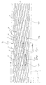
- the expandable intraluminal vascular graft, or prosthesis, 70 is shown to generally comprise a tubular shaped member 71 having first and second ends 72, 73 and a wall surface 74 disposed between the first and second end 72, 73.
- the wall surface 74 is formed by a plurality of intersecting elongate members 75, 76 with at least some of the elongate members 75, 76 intersecting with one another intermediate the first and second ends 72, 73 of the tubular shaped member 71, such as shown at intersection points 77.
- Tubular shaped member 71 has a first diameter, d, which to be hereinafter described in greater detail, permits intraluminal delivery of the tubular shaped member 71 into a body passageway 70 having a lumen already well known in the art.
- tubular shaped member 71 Upon the application from the interior of the tubular shaped member 71 of a radially, outwardly extending force, to be hereinafter described in greater detail tubular shaped member 71 has a second, expanded diameter, d', which second diameter d' is variable in size and dependent upon the amount of force applied to the tubular shaped member 71.
- Elongate members 75, 76 which form wall surface 74 of tubular shaped member 71, may be any suitable material which is compatible with the human body and the bodily fluids (not shown) with which the vascular graft, or prosthesis, 70 may come into contact.
- Elongate members 75, 76 must also be made of a material which has the requisite strength and elasticity characteristics to permit the tubular shaped member 71 to be expanded from the configuration shown in Fig. 1 to the expanded configuration and further to permit the tubular shaped member 71 to retain its expanded configuration with an enlarged diameter d'.
- Suitable materials for the fabrication of tubular shaped member 71 would include silver, tantalum, stainless steel, gold, titanium or any suitable plastic material having the requisite characteristics previously described.
- elongate members 75, 76 are fabricated from 316L stainless steel.
- the elongate members 75, 76 illustrated are small diameter stainless steel wires having a cylindrical cross-section. It should of course be understood that each elongate member 75, 76 could have other cross-sectional configurations, such as triangular, square, rectangular, hexagonal, etc. Further, it is preferable that the plurality of elongate members 75, 76 are fixedly secure to one another where the elongate members 75, 76 intersect with one another, such as at the intersection points 77.
- Elongate members 75, 76 could be fixedly secured to one another in any conventional manner, such as by welding, soldering, or gluing, such as with a suitable epoxy glue; however, it is preferred that the intersection points 77 are one continuous piece.
- tubular member 71 is provided with a relatively high resistance to radial collapse, and the tubular shaped member 71 has the ability to retain its enlarged diameter, d'.
- tubular shaped member 71 is made of continuous, stainless steel wire woven In a criss-crossed tubular pattern to form what can be generally described as a wire mesh tube.
- tubular shaped member, or wire mesh tube, 71 When fabricating tubular shaped member, or wire mesh tube, 71, it can be initially fabricated in the configuration shown in Fig. 1 with diameter, d. Alternatively, it can be fabricated with a diameter which is larger than initial diameter d and after fabrication, tubular shaped member 71 could be carefully collapsed to have diameter d shown in Fig. 1. During the collapsing of tubular shaped member, or wire mesh tube, 71, care must be taken to insure that overlapping of adjacent elongate member 75, 76 is avoided.
- curved connectors 77a Strategically placed about the circumference of the prosthesis 70 are curved connectors 77a, which, intact, for the predominate parts of the stent 70. These connectors shorten the length of the "rectangles" 77, 75, 76, 77, and thus enhance the flexibility of the stent 70. This occurs because the closed “rectangles" 77, 75, 76, 77 can be as small as one cell length (c) along the length of the slots, as compared with the two cell length (2c) seen in certain open "rectangles" 77, 75, 76, 77a. The ratio of the open to closed rectangles can be as low as just greater than 1:1 to as high as 5:1 depending on flexibility desired.
- an "open" cell length is anywhere 1 1/2 and 3 times any "closed” cell length.
- the slots (c) themselves are found to be useful at no larger than 1.5 cm length.
- the new "rectangles" have an open side, creating even greater flexibility.
- the entire length of a stent can range from about 3 cm for a coronary stent to about 18 cm for an aortic stent, with a wall thickness between .0025" and .008".
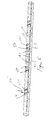
- FIG. 2 and 5 other embodiments of expandable intraluminal vascular graft, or prosthesis, 170, 170' are analogized.
- the intraluminal vascular graft, or prosthesis, 170 of Figs. 2 and 5 will have a plurality of elongate members 75, 76 formed by a plurality of thin bars 78, 79 which are preferably fixedly secured to one another where the bars 78, 79 intersect with one another. Similar to the stent of Figures 1 and 4. Further, there are contained a plurality of curved connectors 77a which help form openings 182 all along the stent.
- tubular shaped member 171 is initially a thin-walled stainless steel tube, and the openings 182 between the intersecting bars and are formed by a conventional etching process, such as electromechanical or laser etching, whereby the resultant structure is a tubular shaped member 171 having a plurality of intersecting elongate members 75, 76.
- the embodiment of graft, or prosthesis, 170 of Fig. 2 likewise can assume an expanded configuration as previously described in connection with Fig. 1, upon the application from the interior of the tubular shaped member 171 of a radially, outwardly extending force. It should be further understood that the embodiment of vascular graft, or prosthesis, 170 of Fig. 2, could also be generally described as a wire mesh tube.
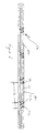
- the stent 270 of the third particular embodiment contains a spiral connector "S" between a series of cell type stents 271, 272.
- These spiral connectors are able to be formed such that they may be either linear or wave-like in shape. The final shape of this connector will depend primarily upon the desire of the user to have greater or lesser flexibility in the area of the articulation between the stents as the spiral connector.
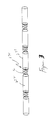
- an expandable intraluminal vascular graft, or prosthesis which may be of the type previously described in connection with Figs. 1, 2, or 3 is disposed or mounted upon a catheter 183.
- Catheter 183 has an expandable, inflatable portion 184 associated therewith.
- Catheter 183 includes means for mounting and retaining 185 the expandable intraluminal vascular graft, of prosthesis, 170 on the expandable, inflatable portion 184 of catheter 183.
- the mounting and retaining means 185 comprises retainer ring members 186 disposed on the catheter 183 adjacent the expandable inflatable portion 184 of catheter 183; and a retainer ring member 186 is disposed adjacent each end 172, 173 of the expandable intraluminal vascular graft, or prosthesis, 170.
- retainer ring members are formed integral with cathecer 183, and the retainer ring member 186 adjacent the leading tip 187 of catheter 183 slopes upwardly and away from catheter tip 187 in order to protect and retain graft or prosthesis, 170 as it is inserted into the lumen 181 of body passageway 180, as to be hereinafter described in greater detail.
- expandable intraluminal graft, or prosthesis, 170 has been disposed upon catheter 183, in the manner previously described, the graft, or prosthesis, 170 and catheter 183 are inserted within a body passageway 180 by catherization of the body passageway 180 in a conventional manner.
- the catheter 183 and graft, or prosthesis, 170 are delivered to the desired location within the body passageway 180, whereat it is desired to expand the lumen 181 of body passageway 180 via intraluminal graft 170, or where it is desired to implant prosthesis 170. Fluoroscopy, and/or other conventional techniques may be utilized to insure that the catheter 183 and graft, or prosthesis, 170 are delivered to the desired location within the body passageway. Prosthesis, or graft, 170 are then expanded by expanding the expandable, inflatable portion 184 of catheter 183, whereby the prosthesis, or graft, 170 is forced radially, outwardly into contact with the body passageway 180.
- the expandable, inflatable portion of catheter 183 may be a conventional angioplasty balloon 188.
- angioplasty balloon 188 may be removed in a conventional manner from body passageway 180.
- catheter 183 may be removed in a conventional manner from body passageway 180.
- catheter 183, having graft or prosthesis, 170 disposed thereon may be initially encased in a convention TeflonTM sheath 189, which is pulled away from prosthesis, or graft, 170, prior to expansion of the prosthesis, or graft, 170.
- tubular shaped member 171 of prosthesis, or graft, 170 initially has the first predetermined, collapsed diameter d as described in connection with Figs. 1 in order to permit the insertion of the wire mesh tube, or tubular shaped member, 171 into the body passageway 180 as previously described.
- the wire mesh tube, or prosthesis 170 is expanded to the second diameter d' and the second, expanded diameter d' is variable and determined by the internal diameter of the body passageway 180.
- the expanded prosthesis 170 upon deflation of angioplasty balloon 188 will not be able to migrate from the desired location within the body passageway 180, nor will the expansion of the prosthesis 170 be likely to cause a rupture of the body passageway 180.
- expandable intraluminal graft 170 When it is desired to use expandable intraluminal graft 170 to expand the lumen 181 of a body passageway 180 having an area of stenosis, the expansion of intraluminal vascular graft 170 by angioplasty balloon 188, allows controlled dilation of the stenotic area and, at the same time controlled expansion of the vascular graft 170, whereby vascular graft 170 prevents the body passageway 180 from collapsing and decreasing the size of the expanded diameter d' of intraluminal vascular graft 170, as shown in Fig. 4, is variable and determined by the desired expanded internal diameter of body passageway 180.
- the expandable Intraluminal graft 170 will not migrate away from the desired location within the body passageway 180 upon deflation of angioplasty balloon 188, nor will the expansion of intraluminal graft 170 likely cause a rupture of body passageway 180.
- the stents of this invention are able to be made of polymeric or metallic materials, which in any event are expandable beyond their elastic limit. Furthermore, they can be made of shape memory materials such as nitinol and may have a certain shape memory imparted upon them also, as is disclosed in the art.
- Stent 70, 170, 270 of the type previously described in connection with Figs. 1, 2, and 3 are shown, and the tubular shaped members 71 of grafts, or prostheses, 170 have a biologically inert coating placed upon wall surfaces 74 of tubular shaped members 71.
- a suitable biologically inert coating would be porous polyurethane, TeflonTM, or other conventional biologically inert plastic materials.
- the coating should be thin and highly elastic so as not to Interfere with the desired expansion of the stent.
- the means for expanding the prosthesis or graft could be a plurality of hydraulically actuated rigid members disposed on a catheter, or a plurality of angioplasty balloons could be utilized by expand the prosthesis or graft. Accordingly, the invention is therefore to be limited only by the scope of the appended claims.
Abstract
Description
Claims (12)
- A tubular stent comprising a generally slotted tube wherein a plurality of slots are spaced around the circumference of a cylindrical member, forming a mesh like configuration around said cylindrical member, and wherein said slots are variable in length.
- A generally tubular stent having a longitudinal axis and containing a plurality of struts arranged circumferentially around a cylinder, and only a predetermined number but less than all of the adjacent ones of said struts connected by connecting members placed at angles generally perpendicular to the longitudinal axis of said cylindrical member to form slots therein and wherein certain slots formed by said struts are not closed.
- A cylindrical stent having a plurality or elongate struts connected by a plurality of circumferentially arranged members, and said circumferentially arranged members generally forming a rectangular shaped configurations about said stent, and wherein a predetermined number certain of said rectangular shaped configurations but less than all of said configurations are completely closed so that the remainder of the rectangular shaped configurations have openings therein.
- A stent containing a plurality of open cells and a plurality of closed cells, said open cells formed by adjacent elongate connectors connected at one end by a connecting member and not connected at a second end, and a closed cell formed by an elongate connecting member adjacent to second elongate connecting member and said first and second elongated connecting members connected by first and second conneccing members.
- The stent of claim 4 wherein a plurality of open connecting is concentrated on one side of the stent to encourage bending in a predetermined direction.
- A pair of stents connected by a connecting member, said connecting member forming a spiral such that said spiral can be expanded both radially and circumferentially.
- The stent of claim 6 wherein said spiral Is wave form.
- The connector of stent of claim 7 wherein said spiral is generally linear in shape.
- The stent of claim 1 wherein at least one slot is about 1 1/2 to 3 times the length cf another slot.
- The stent of claim 2 wherein at least one slot is about 1 1/2 to 3 times the length of another slot.
- The stent of claim 3 wherein at least one slot is about 1 1/2 to 3 times the length of another slot.
- The stent of claim 4 wherein at least one slot is about 1 1/2 to 3 times the length of another slot.
Applications Claiming Priority (2)
| Application Number | Priority Date | Filing Date | Title |
|---|---|---|---|
| US814182 | 1997-03-10 | ||
| US08/814,182 US5911732A (en) | 1997-03-10 | 1997-03-10 | Articulated expandable intraluminal stent |
Publications (2)
| Publication Number | Publication Date |
|---|---|
| EP0864302A2 true EP0864302A2 (en) | 1998-09-16 |
| EP0864302A3 EP0864302A3 (en) | 1999-08-04 |
Family
ID=25214379
Family Applications (1)
| Application Number | Title | Priority Date | Filing Date |
|---|---|---|---|
| EP98301708A Withdrawn EP0864302A3 (en) | 1997-03-10 | 1998-03-09 | Articulated expandable intraluminal stent |
Country Status (5)
| Country | Link |
|---|---|
| US (4) | US5911732A (en) |
| EP (1) | EP0864302A3 (en) |
| JP (1) | JP4067634B2 (en) |
| AU (1) | AU745092B2 (en) |
| CA (1) | CA2231502A1 (en) |
Cited By (4)
| Publication number | Priority date | Publication date | Assignee | Title |
|---|---|---|---|---|
| FR2785174A1 (en) * | 1998-11-03 | 2000-05-05 | Jacques Seguin | BODY CONDUIT EXTENSIONER, ESPECIALLY VASCULAR |
| WO2001030271A2 (en) * | 1999-10-26 | 2001-05-03 | Scimed Life Systems, Inc. | Flexible stent |
| US6773455B2 (en) | 1997-06-24 | 2004-08-10 | Advanced Cardiovascular Systems, Inc. | Stent with reinforced struts and bimodal deployment |
| WO2006024488A2 (en) | 2004-08-30 | 2006-03-09 | Interstitial Therapeutics | Medical stent provided with inhibitors of atp synthesis |
Families Citing this family (193)
| Publication number | Priority date | Publication date | Assignee | Title |
|---|---|---|---|---|
| US20050059889A1 (en) * | 1996-10-16 | 2005-03-17 | Schneider (Usa) Inc., A Minnesota Corporation | Clad composite stent |
| US7204848B1 (en) | 1995-03-01 | 2007-04-17 | Boston Scientific Scimed, Inc. | Longitudinally flexible expandable stent |
| US6033433A (en) * | 1997-04-25 | 2000-03-07 | Scimed Life Systems, Inc. | Stent configurations including spirals |
| EP0884029B1 (en) | 1997-06-13 | 2004-12-22 | Gary J. Becker | Expandable intraluminal endoprosthesis |
| US6071308A (en) * | 1997-10-01 | 2000-06-06 | Boston Scientific Corporation | Flexible metal wire stent |
| US6179867B1 (en) * | 1998-01-16 | 2001-01-30 | Advanced Cardiovascular Systems, Inc. | Flexible stent and method of use |
| AU2891899A (en) * | 1998-03-05 | 1999-09-20 | Boston Scientific Limited | Intraluminal stent |
| US20020099438A1 (en) * | 1998-04-15 | 2002-07-25 | Furst Joseph G. | Irradiated stent coating |
| US6206916B1 (en) | 1998-04-15 | 2001-03-27 | Joseph G. Furst | Coated intraluminal graft |
| US6436133B1 (en) * | 1998-04-15 | 2002-08-20 | Joseph G. Furst | Expandable graft |
| US20030040790A1 (en) * | 1998-04-15 | 2003-02-27 | Furst Joseph G. | Stent coating |
| US7967855B2 (en) | 1998-07-27 | 2011-06-28 | Icon Interventional Systems, Inc. | Coated medical device |
| US8070796B2 (en) | 1998-07-27 | 2011-12-06 | Icon Interventional Systems, Inc. | Thrombosis inhibiting graft |
| US6494879B2 (en) | 1998-10-15 | 2002-12-17 | Scimed Life Systems, Inc. | Treating urinary retention |
| US7214229B2 (en) | 1999-03-18 | 2007-05-08 | Fossa Medical, Inc. | Radially expanding stents |
| US6214037B1 (en) * | 1999-03-18 | 2001-04-10 | Fossa Industries, Llc | Radially expanding stent |
| US6709465B2 (en) | 1999-03-18 | 2004-03-23 | Fossa Medical, Inc. | Radially expanding ureteral device |
| US6273911B1 (en) | 1999-04-22 | 2001-08-14 | Advanced Cardiovascular Systems, Inc. | Variable strength stent |
| SE514718C2 (en) | 1999-06-29 | 2001-04-09 | Jan Otto Solem | Apparatus for treating defective closure of the mitral valve apparatus |
| US6997951B2 (en) | 1999-06-30 | 2006-02-14 | Edwards Lifesciences Ag | Method and device for treatment of mitral insufficiency |
| US7192442B2 (en) * | 1999-06-30 | 2007-03-20 | Edwards Lifesciences Ag | Method and device for treatment of mitral insufficiency |
| US6569193B1 (en) * | 1999-07-22 | 2003-05-27 | Advanced Cardiovascular Systems, Inc. | Tapered self-expanding stent |
| US6679910B1 (en) | 1999-11-12 | 2004-01-20 | Latin American Devices Llc | Intraluminal stent |
| US8458879B2 (en) * | 2001-07-03 | 2013-06-11 | Advanced Bio Prosthetic Surfaces, Ltd., A Wholly Owned Subsidiary Of Palmaz Scientific, Inc. | Method of fabricating an implantable medical device |
| US7507252B2 (en) * | 2000-01-31 | 2009-03-24 | Edwards Lifesciences Ag | Adjustable transluminal annuloplasty system |
| US6989028B2 (en) * | 2000-01-31 | 2006-01-24 | Edwards Lifesciences Ag | Medical system and method for remodeling an extravascular tissue structure |
| US6402781B1 (en) * | 2000-01-31 | 2002-06-11 | Mitralife | Percutaneous mitral annuloplasty and cardiac reinforcement |
| US9522217B2 (en) | 2000-03-15 | 2016-12-20 | Orbusneich Medical, Inc. | Medical device with coating for capturing genetically-altered cells and methods for using same |
| US8088060B2 (en) | 2000-03-15 | 2012-01-03 | Orbusneich Medical, Inc. | Progenitor endothelial cell capturing with a drug eluting implantable medical device |
| US8460367B2 (en) | 2000-03-15 | 2013-06-11 | Orbusneich Medical, Inc. | Progenitor endothelial cell capturing with a drug eluting implantable medical device |
| US9603741B2 (en) | 2000-05-19 | 2017-03-28 | Michael S. Berlin | Delivery system and method of use for the eye |
| US6652579B1 (en) | 2000-06-22 | 2003-11-25 | Advanced Cardiovascular Systems, Inc. | Radiopaque stent |
| US6805704B1 (en) | 2000-06-26 | 2004-10-19 | C. R. Bard, Inc. | Intraluminal stents |
| US7510576B2 (en) * | 2001-01-30 | 2009-03-31 | Edwards Lifesciences Ag | Transluminal mitral annuloplasty |
| US8038708B2 (en) | 2001-02-05 | 2011-10-18 | Cook Medical Technologies Llc | Implantable device with remodelable material and covering material |
| WO2002096275A2 (en) * | 2001-03-05 | 2002-12-05 | Viacor, Incorporated | Apparatus and method for reducing mitral regurgitation |
| CN1531413A (en) * | 2001-03-20 | 2004-09-22 | GMPǿ�ı�����˾ | Rail stent |
| US6890353B2 (en) * | 2001-03-23 | 2005-05-10 | Viacor, Inc. | Method and apparatus for reducing mitral regurgitation |
| US7186264B2 (en) * | 2001-03-29 | 2007-03-06 | Viacor, Inc. | Method and apparatus for improving mitral valve function |
| DE10118944B4 (en) | 2001-04-18 | 2013-01-31 | Merit Medical Systems, Inc. | Removable, essentially cylindrical implants |
| US6719795B1 (en) * | 2001-04-25 | 2004-04-13 | Macropore Biosurgery, Inc. | Resorbable posterior spinal fusion system |
| US6494855B2 (en) * | 2001-05-16 | 2002-12-17 | Scimed Life Systems, Inc. | Draining bodily fluid |
| US6599314B2 (en) | 2001-06-08 | 2003-07-29 | Cordis Corporation | Apparatus and method for stenting a vessel using balloon-actuated stent with interlocking elements |
| US7520892B1 (en) | 2001-06-28 | 2009-04-21 | Advanced Cardiovascular Systems, Inc. | Low profile stent with flexible link |
| US6607554B2 (en) | 2001-06-29 | 2003-08-19 | Advanced Cardiovascular Systems, Inc. | Universal stent link design |
| WO2003009773A2 (en) | 2001-07-26 | 2003-02-06 | Alveolus Inc. | Removable stent and method of using the same |
| US20030078654A1 (en) * | 2001-08-14 | 2003-04-24 | Taylor Daniel C. | Method and apparatus for improving mitral valve function |
| US7052487B2 (en) * | 2001-10-26 | 2006-05-30 | Cohn William E | Method and apparatus for reducing mitral regurgitation |
| US8740973B2 (en) | 2001-10-26 | 2014-06-03 | Icon Medical Corp. | Polymer biodegradable medical device |
| SE524709C2 (en) * | 2002-01-11 | 2004-09-21 | Edwards Lifesciences Ag | Device for delayed reshaping of a heart vessel and a heart valve |
| WO2003055417A1 (en) * | 2001-12-28 | 2003-07-10 | Edwards Lifesciences Ag | Delayed memory device |
| US7125420B2 (en) * | 2002-02-05 | 2006-10-24 | Viacor, Inc. | Method and apparatus for improving mitral valve function |
| US8506647B2 (en) * | 2002-02-14 | 2013-08-13 | Boston Scientific Scimed, Inc. | System for maintaining body canal patency |
| US20030195609A1 (en) * | 2002-04-10 | 2003-10-16 | Scimed Life Systems, Inc. | Hybrid stent |
| US8016881B2 (en) | 2002-07-31 | 2011-09-13 | Icon Interventional Systems, Inc. | Sutures and surgical staples for anastamoses, wound closures, and surgical closures |
| AU2003258240A1 (en) * | 2002-08-15 | 2004-03-03 | Gmp Cardiac Care, Inc | Stent-graft with rails |
| US6878162B2 (en) * | 2002-08-30 | 2005-04-12 | Edwards Lifesciences Ag | Helical stent having improved flexibility and expandability |
| US9561123B2 (en) | 2002-08-30 | 2017-02-07 | C.R. Bard, Inc. | Highly flexible stent and method of manufacture |
| WO2008100783A2 (en) | 2007-02-12 | 2008-08-21 | C.R. Bard Inc. | Highly flexible stent and method of manufacture |
| US20040093056A1 (en) | 2002-10-26 | 2004-05-13 | Johnson Lianw M. | Medical appliance delivery apparatus and method of use |
| US7959671B2 (en) | 2002-11-05 | 2011-06-14 | Merit Medical Systems, Inc. | Differential covering and coating methods |
| US7527644B2 (en) | 2002-11-05 | 2009-05-05 | Alveolus Inc. | Stent with geometry determinated functionality and method of making the same |
| US7637942B2 (en) | 2002-11-05 | 2009-12-29 | Merit Medical Systems, Inc. | Coated stent with geometry determinated functionality and method of making the same |
| US7875068B2 (en) | 2002-11-05 | 2011-01-25 | Merit Medical Systems, Inc. | Removable biliary stent |
| EP1560548A2 (en) * | 2002-11-15 | 2005-08-10 | GMP Cardiac Care, Inc. | Rail stent-graft for repairing abdominal aortic aneurysm |
| AU2003290881A1 (en) * | 2002-11-15 | 2004-06-15 | Gmp Cardiac Care, Inc. | Rail stent |
| US20050033410A1 (en) * | 2002-12-24 | 2005-02-10 | Novostent Corporation | Vascular prothesis having flexible configuration |
| US7846198B2 (en) * | 2002-12-24 | 2010-12-07 | Novostent Corporation | Vascular prosthesis and methods of use |
| US20050165469A1 (en) * | 2002-12-24 | 2005-07-28 | Michael Hogendijk | Vascular prosthesis including torsional stabilizer and methods of use |
| US20040160685A1 (en) * | 2003-01-27 | 2004-08-19 | Everardo Daniel Faires Quiros | Lower rear view mirror (LRVM for short) |
| US7918884B2 (en) * | 2003-02-25 | 2011-04-05 | Cordis Corporation | Stent for treatment of bifurcated lesions |
| US7942920B2 (en) * | 2003-02-25 | 2011-05-17 | Cordis Corporation | Stent with nested fingers for enhanced vessel coverage |
| US20050131524A1 (en) * | 2003-02-25 | 2005-06-16 | Majercak David C. | Method for treating a bifurcated vessel |
| US20040249442A1 (en) * | 2003-02-26 | 2004-12-09 | Fleming James A. | Locking stent having multiple locking points |
| US20040254600A1 (en) * | 2003-02-26 | 2004-12-16 | David Zarbatany | Methods and devices for endovascular mitral valve correction from the left coronary sinus |
| US20080051866A1 (en) * | 2003-02-26 | 2008-02-28 | Chao Chin Chen | Drug delivery devices and methods |
| US20040167610A1 (en) * | 2003-02-26 | 2004-08-26 | Fleming James A. | Locking stent |
| US20040181186A1 (en) * | 2003-03-13 | 2004-09-16 | Scimed Life Systems, Inc. | Medical device |
| US7637934B2 (en) | 2003-03-31 | 2009-12-29 | Merit Medical Systems, Inc. | Medical appliance optical delivery and deployment apparatus and method |
| US7604660B2 (en) | 2003-05-01 | 2009-10-20 | Merit Medical Systems, Inc. | Bifurcated medical appliance delivery apparatus and method |
| US20060136053A1 (en) * | 2003-05-27 | 2006-06-22 | Rourke Jonathan M | Method and apparatus for improving mitral valve function |
| EP1628599A4 (en) * | 2003-05-27 | 2011-12-28 | Viacor Inc | Method and apparatus for improving mitral valve function |
| US7112216B2 (en) | 2003-05-28 | 2006-09-26 | Boston Scientific Scimed, Inc. | Stent with tapered flexibility |
| WO2005018507A2 (en) | 2003-07-18 | 2005-03-03 | Ev3 Santa Rosa, Inc. | Remotely activated mitral annuloplasty system and methods |
| AU2004258950B2 (en) * | 2003-07-23 | 2010-11-04 | Viacor, Inc. | Method and apparatus for improving mitral valve function |
| US7473239B2 (en) * | 2003-08-25 | 2009-01-06 | The University Of Texas System | Single expandable double lumen cannula assembly for veno-venous ECMO |
| WO2005030091A2 (en) * | 2003-09-25 | 2005-04-07 | Scios Inc. | Stents and intra-luminal prostheses containing map kinase inhibitors |
| US7004176B2 (en) * | 2003-10-17 | 2006-02-28 | Edwards Lifesciences Ag | Heart valve leaflet locator |
| US20050177228A1 (en) * | 2003-12-16 | 2005-08-11 | Solem Jan O. | Device for changing the shape of the mitral annulus |
| ATE478629T1 (en) * | 2003-12-17 | 2010-09-15 | Cook Inc | CONNECTED LEG EXTENSIONS FOR AN ENDOLUMINAL PROSTHESIS |
| US7993397B2 (en) * | 2004-04-05 | 2011-08-09 | Edwards Lifesciences Ag | Remotely adjustable coronary sinus implant |
| US7744641B2 (en) * | 2004-07-21 | 2010-06-29 | Boston Scientific Scimed, Inc. | Expandable framework with overlapping connectors |
| US7763067B2 (en) | 2004-09-01 | 2010-07-27 | C. R. Bard, Inc. | Stent and method for manufacturing the stent |
| US7887579B2 (en) | 2004-09-29 | 2011-02-15 | Merit Medical Systems, Inc. | Active stent |
| US7211110B2 (en) * | 2004-12-09 | 2007-05-01 | Edwards Lifesciences Corporation | Diagnostic kit to assist with heart valve annulus adjustment |
| US20070073380A1 (en) * | 2004-12-20 | 2007-03-29 | Vazquez Frank B | Longitudinally expanding, rotating & contracting shaped memory superelastic stent |
| US9107899B2 (en) | 2005-03-03 | 2015-08-18 | Icon Medical Corporation | Metal alloys for medical devices |
| WO2006110197A2 (en) | 2005-03-03 | 2006-10-19 | Icon Medical Corp. | Polymer biodegradable medical device |
| WO2006096251A2 (en) | 2005-03-03 | 2006-09-14 | Icon Medical Corp. | Improved metal alloys for medical device |
| US8323333B2 (en) | 2005-03-03 | 2012-12-04 | Icon Medical Corp. | Fragile structure protective coating |
| US20060264914A1 (en) * | 2005-03-03 | 2006-11-23 | Icon Medical Corp. | Metal alloys for medical devices |
| US7540995B2 (en) | 2005-03-03 | 2009-06-02 | Icon Medical Corp. | Process for forming an improved metal alloy stent |
| CN101484089B (en) | 2005-04-04 | 2015-11-25 | 可挠支架装置公司 | Flexible stent |
| US7731654B2 (en) | 2005-05-13 | 2010-06-08 | Merit Medical Systems, Inc. | Delivery device with viewing window and associated method |
| US7833259B2 (en) * | 2005-07-25 | 2010-11-16 | Cook Incorporated | Fenestrated endoluminal stent system |
| CA2948428C (en) | 2006-02-14 | 2020-06-30 | Angiomed Gmbh & Co. Medizintechnik Kg | Highly flexible stent and method of manufacture |
| EP1991164B1 (en) * | 2006-02-28 | 2017-06-14 | Angiomed GmbH & Co. Medizintechnik KG | Flexible stretch stent-graft |
| US20070219618A1 (en) * | 2006-03-17 | 2007-09-20 | Cully Edward H | Endoprosthesis having multiple helically wound flexible framework elements |
| WO2007117538A2 (en) * | 2006-04-03 | 2007-10-18 | Innerpulse, Inc. | Flexible interconnect assembly for implantable medical devices |
| US7537608B2 (en) * | 2006-05-23 | 2009-05-26 | Boston Scientific Scimed, Inc. | Stent with variable crimping diameter |
| US20080097620A1 (en) | 2006-05-26 | 2008-04-24 | Nanyang Technological University | Implantable article, method of forming same and method for reducing thrombogenicity |
| CN104257450B (en) * | 2006-07-10 | 2017-05-10 | 第一次质量卫生公司 | Resilient Device |
| US10004584B2 (en) | 2006-07-10 | 2018-06-26 | First Quality Hygienic, Inc. | Resilient intravaginal device |
| US10219884B2 (en) | 2006-07-10 | 2019-03-05 | First Quality Hygienic, Inc. | Resilient device |
| US8613698B2 (en) | 2006-07-10 | 2013-12-24 | Mcneil-Ppc, Inc. | Resilient device |
| US8047980B2 (en) | 2006-07-10 | 2011-11-01 | Mcneil-Ppc, Inc. | Method of treating urinary incontinence |
| US7651523B2 (en) * | 2006-07-24 | 2010-01-26 | Cook Incorporated | Intraluminal device with flexible regions |
| US7988720B2 (en) | 2006-09-12 | 2011-08-02 | Boston Scientific Scimed, Inc. | Longitudinally flexible expandable stent |
| US8814930B2 (en) * | 2007-01-19 | 2014-08-26 | Elixir Medical Corporation | Biodegradable endoprosthesis and methods for their fabrication |
| US20130150943A1 (en) | 2007-01-19 | 2013-06-13 | Elixir Medical Corporation | Biodegradable endoprostheses and methods for their fabrication |
| US20080177373A1 (en) | 2007-01-19 | 2008-07-24 | Elixir Medical Corporation | Endoprosthesis structures having supporting features |
| US8333799B2 (en) * | 2007-02-12 | 2012-12-18 | C. R. Bard, Inc. | Highly flexible stent and method of manufacture |
| EP4005537A1 (en) | 2007-02-12 | 2022-06-01 | C.R. Bard Inc. | Highly flexible stent and method of manufacture |
| US8303644B2 (en) * | 2007-05-04 | 2012-11-06 | Abbott Cardiovascular Systems Inc. | Stents with high radial strength and methods of manufacturing same |
| EP2162101B1 (en) * | 2007-06-25 | 2019-02-20 | MicroVention, Inc. | Self-expanding prosthesis |
| US9144508B2 (en) * | 2007-07-19 | 2015-09-29 | Back Bay Medical Inc. | Radially expandable stent |
| CA2700503C (en) * | 2007-09-24 | 2016-05-24 | Ivantis, Inc. | Ocular implants and methods |
| US8734377B2 (en) | 2007-09-24 | 2014-05-27 | Ivantis, Inc. | Ocular implants with asymmetric flexibility |
| US20090082862A1 (en) * | 2007-09-24 | 2009-03-26 | Schieber Andrew T | Ocular Implant Architectures |
| US7740604B2 (en) | 2007-09-24 | 2010-06-22 | Ivantis, Inc. | Ocular implants for placement in schlemm's canal |
| US20170360609A9 (en) | 2007-09-24 | 2017-12-21 | Ivantis, Inc. | Methods and devices for increasing aqueous humor outflow |
| US8808222B2 (en) | 2007-11-20 | 2014-08-19 | Ivantis, Inc. | Methods and apparatus for delivering ocular implants into the eye |
| US8512404B2 (en) * | 2007-11-20 | 2013-08-20 | Ivantis, Inc. | Ocular implant delivery system and method |
| CN101965211A (en) | 2008-03-05 | 2011-02-02 | 伊万提斯公司 | Methods and apparatus for treating glaucoma |
| JP5248165B2 (en) * | 2008-03-31 | 2013-07-31 | テルモ株式会社 | In vivo indwelling stent and biological organ dilator |
| US10898620B2 (en) | 2008-06-20 | 2021-01-26 | Razmodics Llc | Composite stent having multi-axial flexibility and method of manufacture thereof |
| US8206636B2 (en) | 2008-06-20 | 2012-06-26 | Amaranth Medical Pte. | Stent fabrication via tubular casting processes |
| US8206635B2 (en) | 2008-06-20 | 2012-06-26 | Amaranth Medical Pte. | Stent fabrication via tubular casting processes |
| US20100010437A1 (en) * | 2008-07-11 | 2010-01-14 | Miles Robin R | Steerable catheter with distending lumen-actuated curling catheter tip |
| WO2010065970A1 (en) * | 2008-12-05 | 2010-06-10 | Ivantis, Inc. | Methods and apparatus for delivering ocular implants into the eye |
| CA2961767C (en) | 2009-06-23 | 2018-08-14 | Endospan Ltd. | Vascular prostheses for treating aneurysms |
| JP5635605B2 (en) | 2009-07-09 | 2014-12-03 | イバンティス インコーポレイテッド | Intraocular implant and method for delivering an intraocular implant into an eyeball |
| WO2011004374A1 (en) | 2009-07-09 | 2011-01-13 | Endospan Ltd. | Apparatus for closure of a lumen and methods of using the same |
| AU2010271274B2 (en) | 2009-07-09 | 2015-05-21 | Alcon Inc. | Single operator device for delivering an ocular implant |
| WO2011050360A1 (en) | 2009-10-23 | 2011-04-28 | Ivantis, Inc. | Ocular implant system and method |
| WO2011064782A2 (en) | 2009-11-30 | 2011-06-03 | Endospan Ltd. | Multi-component stent-graft system for implantation in a blood vessel with multiple branches |
| EP2509535B1 (en) | 2009-12-08 | 2016-12-07 | Endospan Ltd | Endovascular stent-graft system with fenestrated and crossing stent-grafts |
| EP2528537A4 (en) * | 2010-01-27 | 2016-09-07 | Vascular Therapies Inc | Device and method for preventing stenosis at an anastomosis site |
| CA2789304C (en) | 2010-02-08 | 2018-01-02 | Endospan Ltd. | Thermal energy application for prevention and management of endoleaks in stent-grafts |
| US20110208289A1 (en) * | 2010-02-25 | 2011-08-25 | Endospan Ltd. | Flexible Stent-Grafts |
| US8398916B2 (en) | 2010-03-04 | 2013-03-19 | Icon Medical Corp. | Method for forming a tubular medical device |
| US9510973B2 (en) | 2010-06-23 | 2016-12-06 | Ivantis, Inc. | Ocular implants deployed in schlemm's canal of the eye |
| CA2826022A1 (en) | 2011-02-03 | 2012-08-09 | Endospan Ltd. | Implantable medical devices constructed of shape memory material |
| WO2012111006A1 (en) | 2011-02-17 | 2012-08-23 | Endospan Ltd. | Vascular bands and delivery systems therefor |
| WO2012117395A1 (en) | 2011-03-02 | 2012-09-07 | Endospan Ltd. | Reduced-strain extra- vascular ring for treating aortic aneurysm |
| USD665500S1 (en) | 2011-04-15 | 2012-08-14 | Novostent Corporation | Stent |
| US8574287B2 (en) | 2011-06-14 | 2013-11-05 | Endospan Ltd. | Stents incorporating a plurality of strain-distribution locations |
| US8657776B2 (en) | 2011-06-14 | 2014-02-25 | Ivantis, Inc. | Ocular implants for delivery into the eye |
| ES2568377T3 (en) | 2011-06-21 | 2016-04-28 | Endospan Ltd | Endovascular system with circumferentially overlapping stents |
| EP2729095B1 (en) | 2011-07-07 | 2016-10-26 | Endospan Ltd. | Stent fixation with reduced plastic deformation |
| WO2013030818A2 (en) | 2011-08-28 | 2013-03-07 | Endospan Ltd. | Stent-grafts with post-deployment variable axial and radial displacement |
| WO2013065040A1 (en) | 2011-10-30 | 2013-05-10 | Endospan Ltd. | Triple-collar stent-graft |
| WO2013084235A2 (en) | 2011-12-04 | 2013-06-13 | Endospan Ltd. | Branched stent-graft system |
| US8663150B2 (en) | 2011-12-19 | 2014-03-04 | Ivantis, Inc. | Delivering ocular implants into the eye |
| WO2013120082A1 (en) | 2012-02-10 | 2013-08-15 | Kassab Ghassan S | Methods and uses of biological tissues for various stent and other medical applications |
| US9358156B2 (en) | 2012-04-18 | 2016-06-07 | Invantis, Inc. | Ocular implants for delivery into an anterior chamber of the eye |
| WO2013171730A1 (en) | 2012-05-15 | 2013-11-21 | Endospan Ltd. | Stent-graft with fixation elements that are radially confined for delivery |
| US10617558B2 (en) | 2012-11-28 | 2020-04-14 | Ivantis, Inc. | Apparatus for delivering ocular implants into an anterior chamber of the eye |
| EP2953580A2 (en) | 2013-02-11 | 2015-12-16 | Cook Medical Technologies LLC | Expandable support frame and medical device |
| US9668892B2 (en) | 2013-03-11 | 2017-06-06 | Endospan Ltd. | Multi-component stent-graft system for aortic dissections |
| US9788858B2 (en) | 2013-04-15 | 2017-10-17 | Transseptal Solutions Ltd. | Fossa ovalis penetration using probing elements |
| WO2015075708A1 (en) | 2013-11-19 | 2015-05-28 | Endospan Ltd. | Stent system with radial-expansion locking |
| WO2015179561A1 (en) * | 2014-05-20 | 2015-11-26 | Boston Scientific Scimed, Inc. | Polymer stent with tunable axial and radial flexibility |
| EP3160397A4 (en) | 2014-06-24 | 2018-03-21 | Icon Medical Corp. | Improved metal alloys for medical devices |
| US10022172B2 (en) | 2014-06-25 | 2018-07-17 | Spine Wave, Inc. | Minimally invasive posterolateral fusion |
| US10709547B2 (en) | 2014-07-14 | 2020-07-14 | Ivantis, Inc. | Ocular implant delivery system and method |
| US9730819B2 (en) | 2014-08-15 | 2017-08-15 | Elixir Medical Corporation | Biodegradable endoprostheses and methods of their fabrication |
| US9480588B2 (en) | 2014-08-15 | 2016-11-01 | Elixir Medical Corporation | Biodegradable endoprostheses and methods of their fabrication |
| US9855156B2 (en) | 2014-08-15 | 2018-01-02 | Elixir Medical Corporation | Biodegradable endoprostheses and methods of their fabrication |
| US9259339B1 (en) | 2014-08-15 | 2016-02-16 | Elixir Medical Corporation | Biodegradable endoprostheses and methods of their fabrication |
| EP3206603B1 (en) | 2014-10-14 | 2019-10-02 | Transseptal Solutions Ltd. | Fossa ovalis penetration apparatus |
| CA2967904C (en) | 2014-12-18 | 2023-01-10 | Endospan Ltd. | Endovascular stent-graft with fatigue-resistant lateral tube |
| US9706982B2 (en) | 2015-03-03 | 2017-07-18 | Transseptal Solutions Ltd. | Treatment of appendage openings |
| WO2016204711A1 (en) | 2015-06-16 | 2016-12-22 | Spine Wave, Inc. | Instrument and system for placing graft, implant and graft material for minimally invasive posterolateral fusion |
| CN108135470B (en) | 2015-08-14 | 2021-03-09 | 伊万提斯公司 | Ocular implant with pressure sensor and delivery system |
| US10398503B2 (en) | 2015-10-14 | 2019-09-03 | Transseptal Soulutions Ltd. | Fossa ovalis penetration |
| US11938058B2 (en) | 2015-12-15 | 2024-03-26 | Alcon Inc. | Ocular implant and delivery system |
| US11766506B2 (en) | 2016-03-04 | 2023-09-26 | Mirus Llc | Stent device for spinal fusion |
| ES2873887T3 (en) | 2016-05-16 | 2021-11-04 | Elixir Medical Corp | Stent release |
| US11622872B2 (en) | 2016-05-16 | 2023-04-11 | Elixir Medical Corporation | Uncaging stent |
| CN110799227A (en) | 2017-06-27 | 2020-02-14 | 密歇根州危重病护理医学顾问公司 | Catheter for extracorporeal circulation |
| US10575973B2 (en) | 2018-04-11 | 2020-03-03 | Abbott Cardiovascular Systems Inc. | Intravascular stent having high fatigue performance |
| WO2022150684A1 (en) | 2021-01-11 | 2022-07-14 | Ivantis, Inc. | Systems and methods for viscoelastic delivery |
Citations (1)
| Publication number | Priority date | Publication date | Assignee | Title |
|---|---|---|---|---|
| US4733665A (en) | 1985-11-07 | 1988-03-29 | Expandable Grafts Partnership | Expandable intraluminal graft, and method and apparatus for implanting an expandable intraluminal graft |
Family Cites Families (37)
| Publication number | Priority date | Publication date | Assignee | Title |
|---|---|---|---|---|
| US3657744A (en) * | 1970-05-08 | 1972-04-25 | Univ Minnesota | Method for fixing prosthetic implants in a living body |
| AU8954282A (en) * | 1981-09-16 | 1983-04-08 | Wallsten, H.I. | Device for application in blood vessels or other difficultly accessible locations and its use |
| US4503659A (en) * | 1982-05-10 | 1985-03-12 | Manville Service Corporation | Method of gluing end flaps of a package in an in-line packaging machine |
| US4503569A (en) | 1983-03-03 | 1985-03-12 | Dotter Charles T | Transluminally placed expandable graft prosthesis |
| US5669936A (en) * | 1983-12-09 | 1997-09-23 | Endovascular Technologies, Inc. | Endovascular grafting system and method for use therewith |
| US4580568A (en) * | 1984-10-01 | 1986-04-08 | Cook, Incorporated | Percutaneous endovascular stent and method for insertion thereof |
| US5102417A (en) * | 1985-11-07 | 1992-04-07 | Expandable Grafts Partnership | Expandable intraluminal graft, and method and apparatus for implanting an expandable intraluminal graft |
| US4681110A (en) * | 1985-12-02 | 1987-07-21 | Wiktor Dominik M | Catheter arrangement having a blood vessel liner, and method of using it |
| US4795458A (en) * | 1987-07-02 | 1989-01-03 | Regan Barrie F | Stent for use following balloon angioplasty |
| US4886062A (en) * | 1987-10-19 | 1989-12-12 | Medtronic, Inc. | Intravascular radially expandable stent and method of implant |
| US5133732A (en) * | 1987-10-19 | 1992-07-28 | Medtronic, Inc. | Intravascular stent |
| US5192307A (en) * | 1987-12-08 | 1993-03-09 | Wall W Henry | Angioplasty stent |
| US5266073A (en) * | 1987-12-08 | 1993-11-30 | Wall W Henry | Angioplasty stent |
| CA1322628C (en) * | 1988-10-04 | 1993-10-05 | Richard A. Schatz | Expandable intraluminal graft |
| CH678393A5 (en) * | 1989-01-26 | 1991-09-13 | Ulrich Prof Dr Med Sigwart | |
| CA2026604A1 (en) * | 1989-10-02 | 1991-04-03 | Rodney G. Wolff | Articulated stent |
| FR2671280B1 (en) * | 1991-01-03 | 1993-03-05 | Sgro Jean Claude | SELF-EXHIBITING VASCULAR STENT WITH PERMANENT ELASTICITY, LOW SHORTENING AND ITS APPLICATION MATERIAL. |
| US5135536A (en) * | 1991-02-05 | 1992-08-04 | Cordis Corporation | Endovascular stent and method |
| US5527354A (en) * | 1991-06-28 | 1996-06-18 | Cook Incorporated | Stent formed of half-round wire |
| US5269802A (en) * | 1991-09-10 | 1993-12-14 | Garber Bruce B | Prostatic stent |
| US5443498A (en) * | 1991-10-01 | 1995-08-22 | Cook Incorporated | Vascular stent and method of making and implanting a vacsular stent |
| US5290305A (en) * | 1991-10-11 | 1994-03-01 | Kanji Inoue | Appliance collapsible for insertion into human organs and capable of resilient restoration |
| CA2380683C (en) * | 1991-10-28 | 2006-08-08 | Advanced Cardiovascular Systems, Inc. | Expandable stents and method for making same |
| FR2683449A1 (en) * | 1991-11-08 | 1993-05-14 | Cardon Alain | ENDOPROTHESIS FOR TRANSLUMINAL IMPLANTATION. |
| US5316023A (en) * | 1992-01-08 | 1994-05-31 | Expandable Grafts Partnership | Method for bilateral intra-aortic bypass |
| US5496365A (en) * | 1992-07-02 | 1996-03-05 | Sgro; Jean-Claude | Autoexpandable vascular endoprosthesis |
| JP2703510B2 (en) * | 1993-12-28 | 1998-01-26 | アドヴァンスド カーディオヴァスキュラー システムズ インコーポレーテッド | Expandable stent and method of manufacturing the same |
| US5643312A (en) * | 1994-02-25 | 1997-07-01 | Fischell Robert | Stent having a multiplicity of closed circular structures |
| US5449373A (en) * | 1994-03-17 | 1995-09-12 | Medinol Ltd. | Articulated stent |
| US5733303A (en) * | 1994-03-17 | 1998-03-31 | Medinol Ltd. | Flexible expandable stent |
| US5836964A (en) * | 1996-10-30 | 1998-11-17 | Medinol Ltd. | Stent fabrication method |
| US5591197A (en) * | 1995-03-14 | 1997-01-07 | Advanced Cardiovascular Systems, Inc. | Expandable stent forming projecting barbs and method for deploying |
| US5593442A (en) * | 1995-06-05 | 1997-01-14 | Localmed, Inc. | Radially expansible and articulated vessel scaffold |
| US5607442A (en) * | 1995-11-13 | 1997-03-04 | Isostent, Inc. | Stent with improved radiopacity and appearance characteristics |
| DE29615969U1 (en) * | 1996-02-29 | 1996-10-31 | Medinol Ltd | Stent |
| US5807404A (en) * | 1996-09-19 | 1998-09-15 | Medinol Ltd. | Stent with variable features to optimize support and method of making such stent |
| DE29708879U1 (en) * | 1997-05-20 | 1997-07-31 | Jomed Implantate Gmbh | Coronary stent |
-
1997
- 1997-03-10 US US08/814,182 patent/US5911732A/en not_active Expired - Lifetime
-
1998
- 1998-03-05 AU AU57385/98A patent/AU745092B2/en not_active Ceased
- 1998-03-09 JP JP07671698A patent/JP4067634B2/en not_active Expired - Lifetime
- 1998-03-09 EP EP98301708A patent/EP0864302A3/en not_active Withdrawn
- 1998-03-09 CA CA002231502A patent/CA2231502A1/en not_active Abandoned
-
1999
- 1999-04-21 US US09/296,060 patent/US6238409B1/en not_active Expired - Lifetime
-
2001
- 2001-02-07 US US09/778,148 patent/US6565600B2/en not_active Expired - Lifetime
-
2003
- 2003-03-31 US US10/403,420 patent/US20030191523A1/en not_active Abandoned
Patent Citations (5)
| Publication number | Priority date | Publication date | Assignee | Title |
|---|---|---|---|---|
| US4733665A (en) | 1985-11-07 | 1988-03-29 | Expandable Grafts Partnership | Expandable intraluminal graft, and method and apparatus for implanting an expandable intraluminal graft |
| US4776337A (en) | 1985-11-07 | 1988-10-11 | Expandable Grafts Partnership | Expandable intraluminal graft, and method and apparatus for implanting an expandable intraluminal graft |
| US4733665B1 (en) | 1985-11-07 | 1994-01-11 | Expandable Grafts Partnership | Expandable intraluminal graft,and method and apparatus for implanting an expandable intraluminal graft |
| US4776337B1 (en) | 1985-11-07 | 2000-12-05 | Cordis Corp | Expandable intraluminal graft and method and apparatus for implanting an expandable intraluminal graft |
| US4733665C2 (en) | 1985-11-07 | 2002-01-29 | Expandable Grafts Partnership | Expandable intraluminal graft and method and apparatus for implanting an expandable intraluminal graft |
Cited By (11)
| Publication number | Priority date | Publication date | Assignee | Title |
|---|---|---|---|---|
| US6773455B2 (en) | 1997-06-24 | 2004-08-10 | Advanced Cardiovascular Systems, Inc. | Stent with reinforced struts and bimodal deployment |
| FR2785174A1 (en) * | 1998-11-03 | 2000-05-05 | Jacques Seguin | BODY CONDUIT EXTENSIONER, ESPECIALLY VASCULAR |
| WO2000025702A1 (en) * | 1998-11-03 | 2000-05-11 | Jacques Seguin | Prosthesis for corporeal duct, in particular vascular stent |
| WO2001030271A2 (en) * | 1999-10-26 | 2001-05-03 | Scimed Life Systems, Inc. | Flexible stent |
| WO2001030271A3 (en) * | 1999-10-26 | 2001-09-27 | Scimed Life Systems Inc | Flexible stent |
| US6409753B1 (en) | 1999-10-26 | 2002-06-25 | Scimed Life Systems, Inc. | Flexible stent |
| EP1522275A2 (en) * | 1999-10-26 | 2005-04-13 | SciMed Life Systems, Inc. | Flexible stent |
| EP1522275A3 (en) * | 1999-10-26 | 2005-10-19 | Boston Scientific Limited | Flexible stent |
| US7229470B2 (en) | 1999-10-26 | 2007-06-12 | Boston Scientific Scimed, Inc. | Flexible stent |
| US7637938B2 (en) | 1999-10-26 | 2009-12-29 | Boston Scientific Scimed, Inc. | Flexible stent |
| WO2006024488A2 (en) | 2004-08-30 | 2006-03-09 | Interstitial Therapeutics | Medical stent provided with inhibitors of atp synthesis |
Also Published As
| Publication number | Publication date |
|---|---|
| AU745092B2 (en) | 2002-03-14 |
| US20010016769A1 (en) | 2001-08-23 |
| CA2231502A1 (en) | 1998-09-10 |
| JP4067634B2 (en) | 2008-03-26 |
| US6565600B2 (en) | 2003-05-20 |
| JPH1119219A (en) | 1999-01-26 |
| US5911732A (en) | 1999-06-15 |
| AU5738598A (en) | 1998-09-10 |
| EP0864302A3 (en) | 1999-08-04 |
| US6238409B1 (en) | 2001-05-29 |
| US20030191523A1 (en) | 2003-10-09 |
Similar Documents
| Publication | Publication Date | Title |
|---|---|---|
| US5911732A (en) | Articulated expandable intraluminal stent | |
| US4776337A (en) | Expandable intraluminal graft, and method and apparatus for implanting an expandable intraluminal graft | |
| US5902332A (en) | Expandable intraluminal graft | |
| US5102417A (en) | Expandable intraluminal graft, and method and apparatus for implanting an expandable intraluminal graft | |
| US5556414A (en) | Composite intraluminal graft | |
| US6436133B1 (en) | Expandable graft | |
| EP1933761B1 (en) | Inflatable bifurcation stent | |
| JP4916616B2 (en) | Method for making a self-expanding stent-graft | |
| EP0806191A1 (en) | Expandable intraluminal graft or stent |
Legal Events
| Date | Code | Title | Description |
|---|---|---|---|
| PUAI | Public reference made under article 153(3) epc to a published international application that has entered the european phase |
Free format text: ORIGINAL CODE: 0009012 |
|
| AK | Designated contracting states |
Kind code of ref document: A2 Designated state(s): AT BE CH DE DK ES FI FR GB GR IE IT LI LU MC NL PT SE |
|
| AX | Request for extension of the european patent |
Free format text: AL;LT;LV;MK;RO;SI |
|
| PUAL | Search report despatched |
Free format text: ORIGINAL CODE: 0009013 |
|
| AK | Designated contracting states |
Kind code of ref document: A3 Designated state(s): AT BE CH DE DK ES FI FR GB GR IE IT LI LU MC NL PT SE |
|
| AX | Request for extension of the european patent |
Free format text: AL;LT;LV;MK;RO;SI |
|
| 17P | Request for examination filed |
Effective date: 20000117 |
|
| AKX | Designation fees paid |
Free format text: AT BE CH DE DK ES FI FR GB GR IE IT LI LU MC NL PT SE |
|
| AXX | Extension fees paid |
Free format text: SI PAYMENT 20000117 |
|
| 17Q | First examination report despatched |
Effective date: 20010816 |
|
| STAA | Information on the status of an ep patent application or granted ep patent |
Free format text: STATUS: THE APPLICATION IS DEEMED TO BE WITHDRAWN |
|
| 18D | Application deemed to be withdrawn |
Effective date: 20020227 |