RELATED PATENT DOCUMENTS
Closely related documents include coowned U. S. Patents
4,963,882 entitled "PRINTING OF PIXEL LOCATIONS BY AN
INK JET PRINTER USING MULTIPLE NOZZLES FOR EACH PIXEL OR
PIXEL ROW", 4,965,593 entitled "PRINT QUALITY OF DOT
PRINTERS", 5,555,006 entitled "INKJET PRINTING: MASK-ROTATION-ONLY
AT PAGE EXTREMES; MULTIPASS MODES FOR QUALITY
AND THROUGHPUT ON PLASTIC MEDIA", and 5,561,449,
entitled "POSITION LEADING, DELAY, & TIMING UNCERTAINTY TO
IMPROVE POSITION & QUALITY IN BIDIRECTIONAL INKJET PRINT-ING";
as well as U. S. patent application 08/667,532,
entitled "JITTER-FORM BACKGROUND CONTROL FOR MINIMIZING
SPURIOUS GRAY CAST IN SCANNED IMAGES" and now issued as
U.S. Patent 5,859,928.
FIELD OF THE INVENTION
This invention relates generally to machines and
procedures for printing ultrahigh-resolution color text or
graphics on printing media such as paper, transparency
stock, or other glossy media; and more particularly to a
scanning inkjet machine and method that construct text or
images from individual ink spots created on a printing
medium, in a two-dimensional pixel array. The invention
employs print-mode techniques to optimize ultrahigh-resolution
color image quality vs. operating time.
BACKGROUND OF THE INVENTION
A previous generation of printing machines and procedures
has focused on mixed resolution. These systems most
typically have employed about 24 pixels/mm (600 pixel dots
per inch, or "dpi") in a carriage scan direction transverse
to the printing medium and 12 pixels/mm (300 dpi) in
the print-medium advance direction longitudinal to the
printing medium - or 24 pixels/mm for black and 12 pixels/mm
for chromatic colors, or relatively tall 12 mm
(half-inch) pens for black ink and relatively short 8 mm
(third-inch) pens for chromatic colors; or combinations of
these and other operating-parameter mixtures.
These mixed-resolution systems have been of interest
for obtaining effectively very high quality printing with
a minimum of developmental delay. In the continuing highly
competitive development of inkjet printer products, the
mixed systems have served a very important role because of
many difficult problems associated with attaining a full
ultrahigh resolution - for example 24 pixel/mm pens,
12 mm tall, for all colorants in a color-printing system.
In the current generation of machines, interest has
shifted to solving those many difficult problems. As will
be seen, most of such difficulties have been recognized
for many years, but tend to be aggravated in the ultrahigh-resolution
environment.
EP 0677390 discloses a method of improving the printing
of graphic images and related inkjet dot matrix printing
apparatus. The apparatus includes a scanning inkjet
printhead means for forming a colour image as inkdrops in a
pixel grid of multiple rows and columns, the printhead means
having a nozzle pitch equal to the pixel row spacing.
Printing is carried out by subdividing the grid into an odd
number N of groups of dots which are not horizontally
adjacent N scanning operations are then performed to print
the required image.
US 5,594,478 discloses an inkjet recording apparatus for
divisionally driving a recording head with a plurality of
inkjet orifices grouped into blocks.
EP 0738068 discloses random printing techniques for
liquid ink printers. The techniques include forming masks in
a random mask buffer. The randomness of the masks improves
printing quality and reduces printhead signature problems
resulting from printhead defects including misdirected or
inoperative nozzles or jets.
SUMMARY OF THE DISCLOSURE
The present invention introduces such refinement
by providing apparatus for printing a color image on
a printing medium as claimed in claim 1. The
apparatus includes some
means for forming a color image as inkdrops in a pixel
grid of multiple rows and columns on such medium.
For purpose of generality and breadth in describing
and discussing the invention, these means will be called
the "scanning inkjet printhead means", or sometimes simply
the "scanning means" or "printhead means". The scanning
means cause the rows to be spaced apart by a row spacing,
and the scanning means themselves have a nozzle pitch
equal to that pixel row spacing.
Also included are some means for establishing a
printmask wherein location rules substantially prevent
addressing, within each scan, any immediately neighboring
pixels in any horizontal, vertical or diagonal direction.
Again for purposes of breadth and generality, these means
will be called the "establishing means".
By the term "establishing" it is not intended to limit
the "establishing means" to apparatus which initially
creates a printmask pattern, although of course such real-time
printmask-generating apparatus is within the scope of
the "establishing means" as recited. Rather the phrase
"means for establishing a printmask" is intended more
broadly to encompass as well apparatus which simply holds
and provides information for use in reproducing the effect
of the printmask.
In addition the apparatus of this first main aspect
of the invention includes some means for applying the
printmask to control the inkjet printhead means. These
means will be called the "applying means".
The foregoing may constitute a description or definition
of the invention in its broadest
or most general form. Even in this general form, however,
it can be seen that this aspect of the invention significantly
mitigates the difficulties left unresolved in the
art.
In particular, it may first be noted that the present
invention avoids the previously described arrangement in
which the nozzle spacing is a multiple of the pixel-row
spacing. Accordingly this invention is not subject to the
associated drawbacks of that arrangement: relatively low
throughput, and inflexibility in use.
Moreover while maintaining this advantage the first
main facet of the invention minimizes liquid loading - in
the sense of the amount of ink that can be present on the
printing medium in liquid form at any instant. The invention
accomplishes this by avoiding the nearest-neighbor
conditions that draw separate drops into larger pools
which tend to resist drying. Thus the invention attacks
the problems of coalescence or puddling, and the resulting
phenomena of cockle, pucker, blocking etc. mentioned
earlier.
Although the invention as thus couched in its broadest
form significantly advances the art of ultrahigh-resolution
color inkdrop printing, nevertheless the invention
is preferably practiced in conjunction with several
additional features or characteristics that maximize the
enjoyment of its benefits.
For instance, in one preferred form of the invention,
full inking of each region of the printing medium requires
five passes; and the printmask identifies the pass in
which each pixel is addressed, by this sixteen-by-five
pattern of pass numbers:
| 4 | 1 | 4 | 2 | 3 | 5 | 3 | 5 | 2 | 1 | 4 | 2 | 3 | 5 | 3 | 5 |
| 3 | 5 | 2 | 1 | 4 | 1 | 4 | 2 | 3 | 5 | 2 | 1 | 4 | 1 | 4 | 2 |
| 4 | 2 | 3 | 5 | 3 | 5 | 2 | 1 | 4 | 1 | 3 | 5 | 3 | 5 | 2 | 1 |
| 2 | 1 | 4 | 1 | 4 | 2 | 3 | 5 | 3 | 5 | 4 | 1 | 4 | 2 | 3 | 5 |
| 3 | 5 | 3 | 5 | 2 | 1 | 4 | 1 | 4 | 2 | 3 | 5 | 2 | 1 | 4 | 1. |
As may be noted, none of the pass numbers in this pattern
occurs twice in adjacency in any direction.
In another preferred form of the invention full
inking of each region of the printing medium requires six
passes; and the printmask identifies the pass in which
each pixel is addressed, by this sixteen-by-ten pattern of
pass numbers:
| 1 | 5 | 3 | 4 | 2 | 6 | 1 | 5 | 3 | 4 | 2 | 6 | 1 | 5 | 4 | 6 |
| 4 | 2 | 6 | 1 | 5 | 3 | 4 | 2 | 6 | 1 | 5 | 3 | 4 | 2 | 1 | 3 |
| 1 | 5 | 3 | 4 | 2 | 6 | 1 | 5 | 3 | 4 | 2 | 6 | 1 | 5 | 4 | 6 |
| 4 | 2 | 6 | 1 | 5 | 3 | 4 | 2 | 6 | 1 | 5 | 3 | 4 | 2 | 1 | 3 |
| 5 | 3 | 4 | 2 | 6 | 1 | 5 | 3 | 4 | 2 | 6 | 1 | 5 | 4 | 6 | 1 |
| 2 | 6 | 1 | 5 | 3 | 4 | 2 | 6 | 1 | 5 | 3 | 4 | 2 | 1 | 3 | 4 |
| 5 | 3 | 4 | 2 | 6 | 1 | 5 | 3 | 4 | 2 | 6 | 1 | 5 | 4 | 6 | 1 |
| 2 | 6 | 1 | 5 | 3 | 4 | 2 | 6 | 1 | 5 | 3 | 4 | 2 | 1 | 3 | 4 |
| 3 | 4 | 2 | 6 | 1 | 5 | 3 | 4 | 2 | 6 | 1 | 5 | 4 | 6 | 1 | 5 |
| 6 | 1 | 5 | 3 | 4 | 2 | 6 | 1 | 5 | 3 | 4 | 2 | 1 | 3 | 4 | 2. |
Once again it can be noted that no pass number appears
twice in succession in any direction - including not only
horizontal succession but also vertical and diagonal.
Preferably location rules also substantially prevent
addressing, in each scan, any vertically neighboring
pixels within the entire height of the printmask. For
example in one particular form of this preferred embodiment
of the invention there are ten passes, and the printmask
identifies the pass in which each pixel is addressed,
by this sixteen-by-five pattern of pass numbers:
| 7 | 1 | 6 | 2 | 5 | 8 | 4 | 9 | 3 | 10 | 6 | 2 | 5 | 8 | 4 | 9 |
| 4 | 9 | 3 | 10 | 7 | 1 | 6 | 2 | 5 | 8 | 3 | 10 | 7 | 1 | 6 | 2 |
| 6 | 2 | 5 | 8 | 4 | 9 | 3 | 10 | 7 | 1 | 5 | 8 | 4 | 9 | 3 | 10 |
| 3 | 10 | 7 | 1 | 6 | 2 | 5 | 8 | 4 | 9 | 7 | 1 | 6 | 2 | 5 | 8 |
| 5 | 8 | 4 | 9 | 3 | 10 | 7 | 1 | 6 | 2 | 4 | 9 | 3 | 10 | 7 | 1. |
In still another preferred embodiment of the invention
location rules also substantially prevent addressing, in
each scan, any horizontally neighboring pixels within the
entire width of the printmask. For instance the printmask
advantageously is an eight-by-eight "knight" pattern - as
will be defined hereinafter; or there are four passes and
the printmask identifies the pass in which each pixel is
addressed, by this four-by-four pattern of pass numbers:
| 4 | 1 | 3 | 2 |
| 3 | 2 | 4 | 1 |
| 1 | 4 | 2 | 3 |
| 2 | 3 | 1 | 4. |
Also preferably the printmask prevents addressing of
any immediately neighboring pixels, in any direction,
along boundaries between vertically adjacent swaths, or
horizontally adjacent masks, or both. This particular
preference is applicable to all the major facets or aspects
of the invention.
This invention also provides a method for creating
and using a printmask for improved print quality in an
inkjet printer as claimed in claim 1. The method
includes the step of automatically generating a
series of numbers for use in defining rows or columns -
or both - of a pixel grid for printing in successive
passes of a printhead.
It also includes the step of automatically testing
each number against location rules for minimization of ink
coalescence and puddling. Additionally included is the
step of automatically accumulating the numbers as a patterned
array for defining rows and columns of a pixel grid
for printing in successive passes of a printhead.
In addition this method includes the step of operationally
checking performance of the array, and others
similarly generated, for selection of at least one preferred
array. The method further includes the step of
storing the array in a tangible medium for later automatic
recall and use in controlling a printer.
The foregoing may constitute a description or definition
of the method provided by this invention,
in its broadest or most general form. Even in this form,
however, it can be seen that it
beneficially advances the art by providing a way of creating
new printmasks in a way that can be in large part
automated, and that will nevertheless produce masks which
very strongly deter coalescence problems.
Nevertheless some preferences can be stated for this
facet of the invention too. For example it is preferable
to include the step of recalling and using the stored
pattern from the tangible medium, for use in controlling a
printer.
All of the foregoing operational principles and
advantages of the present invention will be more fully
appreciated upon consideration of the following detailed
description, with reference to the appended drawings, of
which:
BRIEF DESCRIPTION OF THE DRAWINGS
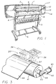
Fig. 1 is an isometric or perspective exterior view
of a large-format printer-plotter which is a preferred
embodiment of the present invention;
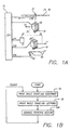
Fig. 1A is a highly schematic block diagram of the
same product, particularly showing key signals flowing
from and to a digital electronic central microprocessor,
to effectuate printing while the pens travel in each of
two opposite directions;
Fig. 1B is a flow chart showing alternation of a full
reciprocation of the pens with each advance of the printing
medium, in some printmodes of particular interest;
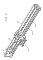
Fig. 2 is a like view of a carriage and carriage-drive
mechanism which is mounted within the case or cover
of the Fig. 1 device;
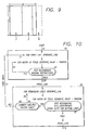
Fig. 3 is a like view of a printing-medium advance
mechanism which is also mounted within the case or cover
of the Fig. 1 device, in association with the carriage as
indicated in the broken line in Fig. 3;
Fig. 4 is a like but more-detailed view of the Fig. 2
carriage, showing the printhead means or pens which it
carries;
Fig. 5 is a bottom plan of the pens, showing their
nozzle arrays;
Fig. 6 is a perspective or isometric view of an ink-refill
cartridge for use with the Fig. 4 and 5 pens;
Fig. 7 is a like view showing several refill cartridges
(for different ink colors) according to Fig. 6 in,
or being installed in, a refill-cartridge station in the
left end of the case in the Fig. 1 device;
Fig. 8 is a very highly enlarged schematic representation
of two usage modes of the ultrahigh-resolution dot
forming system of the present invention;
Fig. 9 is a schematic representation of generic
printmask structures for use in the present invention;
Fig. 10 is a flow chart showing operation of a
printmask-generating utility or development tool, implementing
certain aspects of the present invention;
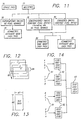
Fig. 11 is a diagram showing relationships between
certain different types of printmodes and printmasks;
Fig. 12 is a diagram schematically showing relationships
between swaths printed in a staggered or semistaggered
printmode;
Fig. 13 is a diagram showing the elemental dimensions
of a generic printmask;
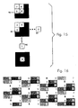
Fig. 14 is a diagram schematically showing relationships
between three notations or conventions for representing
an exemplary set of printmasks;
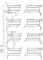
Fig. 15 is a set of diagrams showing pixels among
which relationships are to be tested in the practice of
location-rule aspects of the present invention;
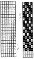
Fig. 16 is a diagram showing pass numbers for printing
of each pixel in an eight-by-eight pixel printmask
which is called a "knight" pattern - for use in eight-pass
printmodes, with eight advances for glossy stock or
four for vinyl;
Fig. 17 is a like diagram for a sixteen-by-five (columns
by rows) printmask, for use in a ten-pass printmode;
Fig. 18 is a like diagram for a different sixteen-by-five
printmask, for use in a five-pass printmode;
Fig. 19 is a like diagram for a sixteen-by-ten printmask,
for use in a six-pass, six-advance printmode;
Fig. 20 is a like diagram for a four-by-four printmask,
for use in a four-pass, four-advance printmode;
Fig. 21 is a like diagram for a four-by-four printmask,
for use in a four-pass, two-advance printmode;
Fig. 22 is a like diagram for a different four-by-four
printmask, for use in a two-pass, single-advance
printmode;
Fig. 23 is a sample of a gray ramp printed using the
present invention - in a so-called "fast" printing mode;
Fig. 24 is a like sample - but for a "normal" print-mode;
and
Fig. 25 is a like sample - but for a "best quality"
mode.
DETAILED DESCRIPTION
OF THE PREFERRED EMBODIMENTS
1. BIDIRECTIONAL HIGH-RESOLUTION COLOR PRINTING
WITH AT LEAST PARTIALLY ALIGNED PENS
A preferred embodiment of the present invention is
the first commercial high-resolution color printer/plotter
to print bidirectionally without full-height offset of the
pens in the direction parallel to the printing-medium advance.
As will be seen, the invention gains several
important advantages by avoiding the extended printzone
found in all bidirectionally operating high-resolution
color printers heretofore.
More specifically, the present invention enables use
of a mechanism that is more compact, light and economical
- and more amenable to operation with a cylindrical platen
of modest diameter. It is less subject to intercolor
banding, differential distortion, and misregistration due
to differential liquid preloading under the several pens.
The printer/plotter includes a main case 1 (Fig. 1)
with a window 2, and a left-hand pod 3 that encloses one
end of the chassis. Within that pod are carriage-support
and -drive mechanics and one end of the printing-medium
advance mechanism, as well as a pen-refill station with
supplemental ink cartridges.
The printer/plotter also includes a printing-medium
roll cover 4, and a receiving bin 5 for lengths or sheets
of printing medium on which images have been formed, and
which have been ejected from the machine. A bottom brace
and storage shelf 6 spans the legs which support the two
ends of the case 1.
Just above the print-medium cover 4 is an entry slot
7 for receipt of continuous lengths of printing medium 4.
Also included are a lever 8 for control of the gripping of
the print medium by the machine.
A front-panel display 11 and controls 12 are mounted
in the skin of the right-hand pod 13. That pod encloses
the right end of the carriage mechanics and of the medium
advance mechanism, and also a printhead cleaning station.
Near the bottom of the right-hand pod for readiest access
is a standby switch 14.
Within the case 1 and pods 3, 13 the carriage assembly
20 (Fig. 2) is driven in reciprocation by a motor 31
- along dual support and guide rails 32, 34 - through
the intermediary of a drive belt 35. The motor 31 is
under the control of signals 31A from a digital electronic
microprocessor 17 (Fig. 1A). In a block diagrammatic
showing, the carriage assembly is represented separately
at 20 when traveling to the left 16 while discharging ink
18, and at 20' when traveling to the right 17 while discharging
ink 19.
A very finely graduated encoder strip 33 is extended
taut along the scanning path of the carriage assembly 20,
20', and read by an automatic optoelectronic sensor 37 to
provide position and speed information 37B for the microprocessor
15. (In the block diagram all illustrated signals
are flowing from left to right except the information
37B fed back from the sensor - as indicated by the associated
leftward arrow.) The codestrip 33 thus enables
formation of color inkdrops at ultrahigh precision (as
mentioned earlier, typically 24 pixels/mm) during scanning
of the carriage assembly 20 in each direction - i. e.,
either left to right (forward 20') or right to left (back
20)
A currently preferred location for the encoder strip
33 is near the rear of the carriage tray (remote from the
space into which a user's hands are inserted for servicing
of the pen refill cartridges). Immediately behind the
pens is another advantageous position for the strip 36
(Fig. 3). For either position, the sensor 37 is disposed
with its optical beam passing through orifices or transparent
portions of a scale formed in the strip.
A cylindrical platen 41 - driven by a motor 42, worm
43 and worm gear 44 under control of signals 42A from the
processor 15 - rotates under the carriage-assembly 20
scan track to drive sheets or lengths of printing medium
4A in a medium-advance direction perpendicular to the
scanning. Print medium 4A is thereby drawn out of the
print-medium roll cover 4, passed under the pens on the
carriage assembly 20, 20' to receive inkdrops 18, 19 for
formation of a desired image, and ejected into the print-medium
bin 5.
The carriage assembly 20, 20' includes a previously
mentioned rear tray 21 (Fig. 4) carrying various electronics.
It also includes bays 22 for preferably four pens
23-26 holding ink of four different colors respectively -
preferably yellow in the leftmost pen 23, then cyan 24,
magenta 25 and black 26.
Each of these pens, particularly in a large-format
printer/plotter as shown, preferably includes a respective
ink-refill valve 27. The pens, unlike those in earlier
mixed-resolution printer systems, all are relatively long
and all have nozzle spacing 29 (Fig. 5) equal to one-twelfth
millimeter - along each of two parallel columns
of nozzles. These two columns contain respectively the
odd-numbered nozzles 1 to 299, and even-numbered nozzles 2
to 300.
The two columns, thus having a total of one hundred
fifty nozzles each, are offset vertically by half the
nozzle spacing, so that the effective pitch of each two-column
nozzle array is approximately one-twenty-fourth
millimeter. The natural resolution of the nozzle array in
each pen is thereby made approximately twenty-four nozzles
(yielding twenty-four pixels) per millimeter.
For resupply of ink to each pen the system includes a
refill cartridge 51 (Fig. 6), with a valve 52, umbilicus
53 and connector nipple 54. The latter mates with supply
tubing within the printer/plotter refill station (in the
left-hand pod 3).
Each supply tube in turn can complete the connection
to the previously mentioned refill valve 27 on a corresponding
one of the pens, when the carriage is halted at
the refill station. A user manually inserts (Fig. 7) each
refill cartridge 51 into the refill station as needed.
In the preferred embodiment of the invention, all
print modes are bidirectional. In other words, consecutive
passes are printed 19, 18 while traveling in both
directions, alternating left-to-right scans 17 with right-to-left
16.
Preferably black (or other monochrome) and color are
treated identically as to speed and most other parameters.
In the preferred embodiment the number of printhead nozzles
used is always two hundred forty, out of the three
hundred nozzles (Fig. 5) in the pens.
This arrangement allows, inter alia, for software/firmware
adjustment of the effective firing height of the
pen over a range of ±30 nozzles, at approximately 24
nozzles/mm, or ±30/24 = ±1½ mm, without any mechanical
motion of the pen along the print-medium advance direction.
Alignment of the pens can be checked automatically,
and corrected through use of the extra nozzles. As will
be understood, the invention is amenable to use with a
very great variety in the number of nozzles actually used.
The system of the preferred embodiment has three
printing speed/quality settings, which determine resolution,
number of passes to complete inking of each swath
(or more precisely each subswath), and carriage velocities
as approximately:
| | best quality | normal | fast |
| resolution (pixels/mm) | 24 | 12 | 12 |
| passes to complete swath | 8 or 10 | 4 or 6 | 2 |
| carriage velocity (cm/sec) | 51 or 63½ | 63½ | 63½. |
The varying choices indicated here are for correspondingly
various media - for example carriage velocity is 63½
cm/sec, except that 51 cm/sec is used for best-quality
printing on glossy stock. Resolution is the same in both
horizontal and vertical directions,
i. e. row and column
spacings are the same so that pixels 57 (Fig. 8) are 24 mm
square for all settings.
All printing, even the lower-resolution (12 pixel/mm)
operation, is actually controlled and produced on the
high-resolution (24-by-24 pixel/mm) grid. High-resolution
printing, however, calculates the inking for each position
in the grid independently, and implements that inking
independently with one or more inkdrops 56 in each pixel.
Low-resolution printing instead calculates the inking
only for every other position in the grid (along each of
the perpendicular axes or dimensions) and implements that
inking with one or more double-height, double-width compound
inkdrop structures 58 - each made up of a two-by-two
assemblage of individual inkdrops. Since calculations
are done for only half the rows and half the columns, the
number of points calculated is just one quarter of all the
points in the grid.
2. RANDOMIZED MASKS
(a) General discussion - A printmask is a binary
pattern that determines exactly which inkdrops are printed
in a given pass or, to put the same thing in another way,
which passes are used to print each pixel. In a printmode
of a certain number of passes, each pass should print -
of all the inkdrops to be printed - a fraction equal
roughly to the reciprocal of that number.
As a practical matter, however, printmasks are designed
to deal with the pixels to be addressed, rather
than "printed". The difference resides in the details of
an individual image which determine whether each particular
pixel will be printed in one or another color, or
left blank.Thus a printmask is used to determine in which pass
each pixel will be addressed, and the image as processed
through various other rendition steps will determine
whether each addressed pixel is actually printed, and if
so with what color or colors. The printmask is used to,
so to speak, "mix up" the nozzles used, as between passes,
in such a way as to reduce undesirable visible printing
artifacts discussed earlier - banding, etc.Whereas prior attention has focused upon dither masks
as the sources of patterning and other artifacts, the
present invention attempts to isolate the contributions of
printmasks to these problems - and to their solutions.
In particular this invention pursues the elaboration of
randomization as a paradigm in printmasks.This pursuit is totally contrary to all the wisdom of
the art heretofore, which has been uniformly devoted to
printmask modules and design techniques that are entirely
systematic and repetitive - precisely the opposite of
random. Through this present contrarian approach a surprisingly
high degree of success has been obtained.
(b) Masks according to the present invention - In
the present preferred embodiment, a common printmask is
used for each color (but that common mask is different for
different modes). Moreover the common mask used for each
color is synchronized, in the sense that each pixel is
addressed in the same pass for all color planes.
As a very general rule, for preferred embodiments of
the present invention two main kinds of masks may be
recognized:
"one out of four" masks for most "normal" & "fast"
print-quality settings - except average one out
of six for some media, and "one out of eight" masks, for the "best quality"
setting - except an average one out of ten for
matte.
The phrase "one out of four" means that each nozzle is
fired at one-quarter of the maximum permissible frequency,
and analogously for "one out of eight".Printmasks according to the present invention have
been developed with a focus on single-field masks. A
printmask "field"
F (Fig. 9) is a mask unit, or building
block, whose width measured in pixels is equal to the
number of passes.Thus a "single-field" printmask is one whose overall
width
W equals the number of passes. The width in pixels
of a multiple-field mask can be integrally divisible by
the width as so defined (
i. e., by the number of passes),
or can have an integral remainder
R, called a residual.
(c) Software design tool used in implementing the
present invention - The basic strategy for creating
single-field print masks is massive random iteration,
using a simple algorithm implemented as a software design
tool written in the "C" programming language and operating
in an ordinary general-purpose computer - with the results
subject to application of location rules. The
location, or dot-placement, rules are taken up in a later
subsection of this document.
The program begins with entry of a so-called "seed"
61 (Fig. 10) for use by the function "rand()" of the "C"
language. The program uses an internal printmask data
structure containing width, height, data, current line,
current value, and temporal neighbors to current value.
Within the first module 62, the algorithm generates
the first line of a printmask, one pixel value at a time,
from the seed and the rand() function, and the location
rules. Eventually each "pixel value" will be interpreted
as the pass number in which the corresponding pixel is
addressed.Thus the "Generate_Line" function within the first
module 62 as seen consists of the "Generate_Value" function,
using the rand() function seeded from the command
line as already mentioned, combined with a test 63 and a
feedback path 64 in event of failure.The line is tested against the location rules, either
after completion of the entire line or after addition of
each pixel value. Given that so far there are no other
lines of data, the number of restrictions in the first-line
block 62 is minimal. If the line (or individual
value, depending on the testing protocol) is not valid, it
is discarded and a new one is generated. This procedure
is iterated until a valid first line has been created and
can be printed out 65 for the designer's reference.Next the program enters the main loop 66. Operation
here closely parallels the first-line module 62, diverging
in only three principal regards:
- the testing 67 is more elaborate because of the
greater number of constraints from already established
lines,
- testing at the bottom line of the mask is particularly
elaborate since it includes a test against the
already-established top line, which will be vertically
adjacent when the mask is stepped over the full
pixel grid, and
- an extra test 68 is included to protect the system
against cycling indefinitely when earlier-established
values or lines pose an intractable selection problem
for later values or lines.
As to the last-mentioned test, it permits recycling 69 -
still within the main loop 66 - up to a predefined limiting
number of failures, but then discards the entire
candidate mask and follows the loop path 71 to start the
whole procedure again. Such complete failures may seem
catastrophic but actually are very inexpensive in machine
time and almost insignificant in terms of designer time.Ideally, the overall effect of the procedure described
is to produce both row randomization and column
randomization. In other words, it is desired that the
pass used to print each row (considering, to take a simplified
example, only pixels in a particular column) be
selected at random; and that the row used to print each
column also be selected at random.As a practical matter the masks generated by this
procedure may be denominated "randomized" or "semirandom":
they are developed through use of random numbers, but then
subjected to exclusions which in many cases are quite
rigorous. Naturally the finished array cannot be regarded
as truly random, since a truly random array would have
many coincidences that are forbidden in this environment.During this preliminary generation stage the program
is simply generating a very special numerical array, but
naturally the array takes on solid physical meaning in the
later usage stage - as the numerical pattern is applied
directly to control electromechanical operation of the
printer.The algorithmic procedure described has been used to
make eight-by-fifteen-pixel, eight-pass masks as part of
preferred embodiments of the present invention, and some
smaller masks too as will be seen. It is very generally
characteristic of the most successful masks, used for the
"best quality" settings in ultrahigh-resolution bidirectional
color printers/plotters, that they are much larger
than printmasks employed heretofore. Some masks used in
the preferred embodiment of the invention are sixteen pixels
wide and one hundred ninety-two pixels tall - that
is, the width 87 (Fig. 13) is sixteen pixels and the
height 88 is one hundred ninety-two pixels.Very small masks, and particularly very simple ones
such as that in Fig. 21, do continue to have a place in
resolving fast-mode requirements for the relatively less
temperamental printing media. Such masks are easy to work
out by hand since the number of possibilities is quite
small; accordingly the algorithmic approach has generally
not been used for the very small masks.
(d) Designer participation to perfect the masking for
each operating-parameter set - The objective of these
mask-generation exercises is to elaborate randomized masking
as a means for minimizing patterning artifacts and
excess inking. The proof of this pudding thus cannot be
obtained from the degree of randomization actually imparted
to given masks, for the artifacts and overinking
problems involved are complex products of interactions
between ink and media.
These interactions at the present writing are, with
some exceptions, inordinately unpredictable. The physics
of microcoalescence, the chemistry of inks and paper
sizing, the biochemistry of some fiber-based print media
and the electrostatics of others that are synthetic, all
intertwine to produce a morass of variability in observable
behaviors - which often seems to go beyond the
merely bewildering to the truly temperamental.Accordingly the present invention relies heavily upon
human observation, and human esthetic evaluation, to select
actually useful solutions from those generated. The
selection is based on actual trial of the printmasks, as
applied in printing of both saturated and unsaturated
images.Massive trial and error is involved in finding the
best: some masks are better for some combinations of
medium and quality/speed requirements, other masks for
other combinations. Through extensive testing the invention
has settled upon three masks, for use at different
print-quality settings, for each medium.
(e) Further refinement - As noted earlier, a randomized
printmask according to the present invention may, as
a finished product, be rather far from random. The relatively
stringent location rules (see section 4 below)
which are responsible for this particularity in selection
are in part due to firing-frequency constraints or the
strength of coalescence in modern inks.
In the foreseeable future with advances in the relevant
electronic and chemical systems a relaxation of both
these types of constraint may be expected. The result
should be a greater degree of randomness in the printmask
generating process - and more-random patterns in the
actual finished-product masks.
Such developments will lead to continuingly improved
print quality. Such quality improvements may in particular
materialize in, for example, even images printed using
the fast-mode settings.
Another area of contemplated extension of the present
work is in the direction of multiple-field masks with no
"residual" as previously defined; then multiple-field
masks with a residual; and also customizable dot-placement
rules. All such refinements are within the scope of the
invention as defined by certain of the appended claims.
3. SEMISTAGGERED PRINTMODE
(a) Terminology - For present purposes a "swath" is
a print region defined by the number of available and
actually used nozzles of a pen and the actually used width
of a printing medium. In a "single pass" print mode 76
(Fig. 11), all nozzles of a pen are fired to provide
complete coverage for a given swath of image data.Single-pass modes have the advantage of speed, but
are not optimal in terms of coalescence or ink loading.
Therefore swaths are often printed in multipass modes 77,
with each swath containing only part of the inking needed
to complete an image in some region of the print medium.In this case only a fraction of all the nozzles fire
in each pass, in each column of the pixel grid. Multipass
color printing heretofore has created swaths that were
either superimposed 78 or staggered 80.In the case of superimposed swaths 78, a sequence of
printmasks is used, one after another, all to print one common portion of the image. Only then is the page advanced
- by the full swath height, since inking has been
completed for the subject portion - and then the next
superimposed-swath portion of the image is printed.Given that all the swaths are printed one on top of
another, each pass must be different or "asymmetric" to
achieve complete coverage without duplication. This
scheme tends to result in banding and is not highly valued
for the current generation of printer products.In the case of staggered swaths 80 a constant pixel
offset is used to successively advance the pen during
printing, through some fraction of the swath height. By
virtue of this repetitive stepping of the printing medium,
resulting printed swaths overlap in the direction of
print-medium advance. Either symmetric masking 82 or
asymmetric masking 83 may be adapted to staggered swaths
80 - as explained at some length in the Cleveland patent
5,555,006 mentioned earlier.An example appears very schematically in Fig. 12.
Here the vertical advance 85 - by successive small offsets
86 - represents successive placements of swaths 1-4,
by virtue of the printing-medium advance (in the opposite
direction to the arrow 85).(In this drawing the slight horizontal offsets between
swath rectangles 1, 2, . . . are included only to
make it easier to visualize the successive swath positions.
In actual printing of course there is no such
horizontal displacement.)As in the case of superimposed swaths, each staggered
swath contains only part of the inking needed to complete
an image strip - but now, since the swaths are not all
laid down in the same place, that "strip" is only a fraction
of the area of any one of the swaths. Ignoring end
effects at top and bottom of a page (or sheet, or length)
of the medium, that elemental "strip" in which the number
of passes needed for completion can be evaluated may be
called a "subswath" or "band".Thus for instance in Fig. 12 the only subswath that
is actually shown as complete - i. e., with inking from
the four swaths needed to complete its image elements -
is the strip actually containing the numeral "4", adjacent
to the offset marking "86". The top three subswaths
(containing the numerals "1" through "3", as drawn) require
earlier-formed swaths for completion; while the
bottom three (containing no numerals) require later-formed
swaths for completion.The height 86 of a subswath or band is ordinarily
equal to the offset distance of any two successive offset
swaths - i. e., the vertical distance by which they are
staggered. This offset, which again is normally a fraction
of the overall swath height, is often expressed in
pixels.
(b) A hybrid mode, novel to color printing - The
present invention employs a bidirectional color printmode
79, incorporating a hybrid of the superimposed swaths 78
and staggered swaths 80 which may be called "semistaggered".
In this system the pens print while traveling in
each direction, and the printing medium is advanced as for
staggered swaths - but not after every pass, rather
instead only after every other pass.
More specifically, the medium advances 42A (Fig. 1B)
after each full reciprocation 19, 18 of the pen carriage,
and the distance of that advance is most commonly a fraction
of the height of each used nozzle array (i. e.,
swath). As to successive passes between which the medium
is not advanced, the operation is as for superimposed
swaths; as to successive passes between which the medium
is advanced, the operation is as for staggered swaths.
As explained earlier, semistaggering of swaths is
readily exploited to substantially eliminate hue shifts
and also eliminates or greatly minimizes certain directional
types of coalescence artifacts. It is amenable to
use with printmasks that minimize overinking problems.
An example of multipass staggered-swath masking
employed in preferred embodiments of the present invention
may be represented in any of at least three equivalent
notations 91, 92, 93 (Fig. 14). The most graphically
plain notation 92 is essentially a representation of a
part of the pixel grid, as addressed in each of four
passes.
In that notation each pass is represented by a separate
rectangle containing numerals (ones and zeroes) in
rows and columns. Each row in each rectangle is part of a
row in a particular portion of the overall pixel grid of
the image, and each column in each rectangle is part of a
column in the same portion of the overall pixel grid. In
operation these rectangles are repeatedly stepped, so that
the pattern is reused many times; however, in most preferred
high-quality printmodes the mask is much larger
than the example, so that considerably less repetition is
present.
All four rectangles represent the same pixel-grid
portions. Thus each numeral ("1" or "0") inside the
rectangles represents what happens at a specific pixel in
part of the overall pixel grid.
In these representations a "1" means that that particular
pixel is addressed - i. e., printed if there is
anything to print - during the pass represented by the
rectangle under consideration.
Hence in the first pass the system addresses the
pixel second from the left in the top row, the pixel at
the far right in the second row, and that at the far left
in the third row. It also addresses the pixel third from
the left in the bottom row.
Exactly the same thing is shown by the numbers 91 at
left of the diagram - i. e., the numerals "4", "1", "8"
and "2" - which are simply hexadecimal (or decimal)
encodings of the patterns within the rectangles read as
binary numbers. In other words, "0100" binary is equal to
"4" in hexadecimal or decimal notation, "0001" is equal to
"1" in hex, "1000" to "8" in hex and "0010" to "2".
Again the same is shown by picking out the numerals
"1" inside the single rectangle 93 at the right. Each
such "1" means that the pixel position where the "1"
appears is printed in pass number one - the topmost of
the rectangles 92 already discussed.
Correspondingly the numerals "3142" across the top
row of the rectangle 93 mean that the pixel positions in
which these numerals appear are addressed in, respectively,
passes number three, one, four and two. This
system can be related to the central rectangles 92 by
noting which of those rectangles 92 has a "1" in the same
respective pixel positions: the third rectangle for the
top-left pixel, first rectangle for the second pixel, etc.
Although as noted above the advance distance is
ordinarily a fraction of the swath height, a two-pass/one-advance
mode such as shown in Fig. 21 requires a full-height
advance. In such a case successive swath pairs are
abutted, leading to some banding; however, Fig. 21 does
represent an optimal fast mode for certain media.
4. LOCATION RULES
As mentioned earlier, one ideal objective is row and
column randomization, to minimize patterning while maintaining
throughput. On the other hand, another important
ideal objective is wide separation between inkdrops laid
down in the same pass - and also in temporally nearby
passes - to minimize puddling while maintaining throughput.
These objectives are inconsistent, since truly random
pass assignments would occasionally produce nearer neighbors
than consistent with good liquid management. What is
desired is an optimum tradeoff between the two ideals.
Most-highly preferred embodiments of the present
invention follow these rules:
- no immediate neighbors in any direction - horizontal,
vertical or diagonal;
- no more than one pixel in any row, within the entire
width of the printmask;
- no more than one pixel in any column, within the
entire height of the printmask;
- no immediate neighbors in any direction in the immediately
preceding pass; and
- adherence to the no-immediate-neighbors rule across
the seams of two vertically abutted masks, or horizontally
abutted masks, or both.
The first of these rules derives from well-known coalescence
or puddling considerations, i. e. from concerns
about overinking. It focuses upon immediately adjacent
horizontal neighbor 4 (Fig. 15) - where the center pixel
95 in the diagram represents a pixel currently under
consideration - and also immediately adjacent vertical
neighbor 5, and immediately adjacent diagonal neighbor 3.
The second rule actually arises from firing-frequency
limitations, as mentioned earlier, but also of course
helps to minimize overinking by spreading printed dots as
much as possible. It focuses on "firing-frequency neighbors"
2.
For current pens the maximum firing frequency is 7.5
kHz, and a design objective is to stay at least a factor
of two below that value. In most of the selected masks
the effective frequency is four to eight times lower than
that value, for a very fully effective margin of error.
The third rule is directed to overinking, and focuses
on "vertical frequency" neighbors 1. The fourth rule is
concerned with the same, but in regard to possibly-incompletely-dried
inkdrops deposited in the immediately preceding
pass - i. e., what may be called a "horizontal-temporal"
neighbor 6, "vertical-temporal" neighbor 8, and
"diagonal-temporal" neighbor 7.
The fifth and final rule is essentially the same as
the first but focused upon the regions where adjoining
masks come together.
Thus positions 1 and 2 are influenced primarily by
pen parameters (firing capabilities), while the other
positions are critical for ink and media artifacts.
Generally it has been possible to satisfy all the
criteria stated, in eight-pass modes (i. e., printmasks
with at least eight rows). Inadequate flexibility is
available in six- and four-pass modes; hence some relaxation
of the rules is required. For example in a four-pass
mode the firing is one in four rather than one in
eight.
5. ACTUALLY SELECTED MASKS
Figs. 16 through 21 display the masks chosen from
those randomly generated, after testing as described
above. As mentioned earlier, some of the smaller masks
were generated manually but still with attention to selection
of the numbers at random.
The mask of Fig. 16 was found to produce best printed
image quality for glossy stock, and also for a vinyl
printing medium, and accordingly was selected for use at
the "best" mode setting for those two media. It is familiarly
called a "knight" printmask because the pixels
assigned to each pass appear, relative to one another, two
pixels over and one down - like the move of the piece
called a "knight" in the game of chess.
The Fig. 17 mask when tested produced best image
quality on matte stock, and Fig. 18 best image quality
when backlit - in other words, used for overhead projection
or simply in a backlit display frame as in some types
of advertising displays. It is a "two hundred percent of
ink" mode, in which all normal inking is doubled. The
mask of Fig. 17 is used at the "best" print-quality setting
on matte, and Fig. 18 for backlit transparencies.
The Fig. 19 mask is used in the "normal" setting for
glossy, heavy matte and vinyl. Inspection of the information
shows clearly that several of the location rules are
relaxed.
Fig. 20 shows a mask used for "normal" printing on
backlit transparency media (at two hundred percent inking),
and also for "fast" printing on glossy and vinyl
stock - all at four passes and four advances. Fig. 21 is
used for "normal" printing on matte, with four passes and
two advances; and Fig. 22 is used at the "fast" setting on
a matte medium, with two passes and one advance.
The mask of Fig. 22 at a glance may seem trivial but
actually is the product of considerable thought. As shown
in Fig. 5, each printhead is made with - pursuant to convention
- two rows of nozzles, the two rows being offset
by half the nozzle spacing in each row. If a printmode
happens to call for addressing, say, all odd-numbered
nozzles in one pass and all even in the next pass, this
seemingly arbitrary specification has a physical significance
which may be unintended: in heavily inked regions,
what will fire is in the first pass the entire left-hand
column of nozzles and then, in the second, the entire
right-hand column.
As a practical matter of constructional detail, pens
are generally made with one common ink-supply channel
supplying all the ink chambers in the left-hand row, and
another distinct common channel supplying all the chambers
in the right-hand row. Firing all odd or all even nozzles
therefore selectively drains only one or the other supply
channel, tending through liquid-flow impedance effects to
aggravate any tendency of some nozzles to fire weakly.
These may be, for example, the nozzles furthest from the
channel source inlets - or those which happen to have
been made with aperture sizes low-within-tolerance.
The mask of Fig. 22 calls for firing in a single pass
(pass "1", for example) two vertically adjacent pixels in
the upper right corner of the mask - which means two
nozzles in immediate succession in the numbering sequence.
These are, physically, one adjacent nozzle in each of the
two columns. Thereby liquid loading is distributed equally
between the two supply channels, not concentrated in
one or the other. The same sharing of the hydraulic
loading is seen whichever pass is considered.
This thinking was enough to include the Fig. 22 mask
among those which should be subjected to comparative testing.
In that testing it was found that the Fig. 22 mask
provided slightly better image quality than its natural
alternative, a plain checkerboard pattern. Accordingly
the Fig. 22 mask has been adopted for use - but only on
matte stock, for which coalescence problems are at a
minimum.
6. OPERATION USING THE SELECTED MASKS
In operation the masks are simply called up automatically.
They are selected by the combination of print-quality
and print-medium settings which a user of the
printer/plotter enters at the control panel 12, as verified
by the display 11.
Each pass number in a particular cell of a mask is
applied directly by the system central processor, to cause
the carriage drive 31, medium-advance drive 42-44, encoder
sensor 37, and pen nozzles (Fig. 5) with associated firing
devices all to cooperate in implementing the pass-number
indication. That is, they cooperate in such a way that
all the pixels corresponding to that particular cell will
be printed during the indicated pass - if there is anything
to print in those pixels respectively.
The physical results may be seen directly in Figs. 23
through 25, which should indicate clearly the relative
quality levels available - with complementary speeds of
printing - through use of the present invention.
The above disclosure is intended as merely exemplary,
and not to limit the scope of the invention - which is to
be determined by reference to the appended claims.