EP0863384A1 - Circuit and method for the operation of a position sensor using Hall elements - Google Patents
Circuit and method for the operation of a position sensor using Hall elements Download PDFInfo
- Publication number
- EP0863384A1 EP0863384A1 EP98103698A EP98103698A EP0863384A1 EP 0863384 A1 EP0863384 A1 EP 0863384A1 EP 98103698 A EP98103698 A EP 98103698A EP 98103698 A EP98103698 A EP 98103698A EP 0863384 A1 EP0863384 A1 EP 0863384A1
- Authority
- EP
- European Patent Office
- Prior art keywords
- hall element
- activated
- hall
- hall elements
- control unit
- Prior art date
- Legal status (The legal status is an assumption and is not a legal conclusion. Google has not performed a legal analysis and makes no representation as to the accuracy of the status listed.)
- Granted
Links
Images


Classifications
-
- G—PHYSICS
- G01—MEASURING; TESTING
- G01D—MEASURING NOT SPECIALLY ADAPTED FOR A SPECIFIC VARIABLE; ARRANGEMENTS FOR MEASURING TWO OR MORE VARIABLES NOT COVERED IN A SINGLE OTHER SUBCLASS; TARIFF METERING APPARATUS; MEASURING OR TESTING NOT OTHERWISE PROVIDED FOR
- G01D5/00—Mechanical means for transferring the output of a sensing member; Means for converting the output of a sensing member to another variable where the form or nature of the sensing member does not constrain the means for converting; Transducers not specially adapted for a specific variable
- G01D5/12—Mechanical means for transferring the output of a sensing member; Means for converting the output of a sensing member to another variable where the form or nature of the sensing member does not constrain the means for converting; Transducers not specially adapted for a specific variable using electric or magnetic means
- G01D5/14—Mechanical means for transferring the output of a sensing member; Means for converting the output of a sensing member to another variable where the form or nature of the sensing member does not constrain the means for converting; Transducers not specially adapted for a specific variable using electric or magnetic means influencing the magnitude of a current or voltage
- G01D5/142—Mechanical means for transferring the output of a sensing member; Means for converting the output of a sensing member to another variable where the form or nature of the sensing member does not constrain the means for converting; Transducers not specially adapted for a specific variable using electric or magnetic means influencing the magnitude of a current or voltage using Hall-effect devices
- G01D5/145—Mechanical means for transferring the output of a sensing member; Means for converting the output of a sensing member to another variable where the form or nature of the sensing member does not constrain the means for converting; Transducers not specially adapted for a specific variable using electric or magnetic means influencing the magnitude of a current or voltage using Hall-effect devices influenced by the relative movement between the Hall device and magnetic fields
-
- G—PHYSICS
- G01—MEASURING; TESTING
- G01D—MEASURING NOT SPECIALLY ADAPTED FOR A SPECIFIC VARIABLE; ARRANGEMENTS FOR MEASURING TWO OR MORE VARIABLES NOT COVERED IN A SINGLE OTHER SUBCLASS; TARIFF METERING APPARATUS; MEASURING OR TESTING NOT OTHERWISE PROVIDED FOR
- G01D5/00—Mechanical means for transferring the output of a sensing member; Means for converting the output of a sensing member to another variable where the form or nature of the sensing member does not constrain the means for converting; Transducers not specially adapted for a specific variable
- G01D5/12—Mechanical means for transferring the output of a sensing member; Means for converting the output of a sensing member to another variable where the form or nature of the sensing member does not constrain the means for converting; Transducers not specially adapted for a specific variable using electric or magnetic means
- G01D5/244—Mechanical means for transferring the output of a sensing member; Means for converting the output of a sensing member to another variable where the form or nature of the sensing member does not constrain the means for converting; Transducers not specially adapted for a specific variable using electric or magnetic means influencing characteristics of pulses or pulse trains; generating pulses or pulse trains
- G01D5/249—Mechanical means for transferring the output of a sensing member; Means for converting the output of a sensing member to another variable where the form or nature of the sensing member does not constrain the means for converting; Transducers not specially adapted for a specific variable using electric or magnetic means influencing characteristics of pulses or pulse trains; generating pulses or pulse trains using pulse code
- G01D5/2497—Absolute encoders
Definitions
- the invention relates to a method for operating a position transmitter, preferably a rotary encoder that has Hall elements, according to the preamble of claim 1 and a position sensor according to the preamble of claim 10 for performing the method.
- Encoders have long been known from the prior art have a magnetic division with a code structure. According to the DE 44 42 371 A1 of the applicant are characterized by such divisions multi-track alternating magnetization of a rotationally symmetric Body, which is proportional to that supplied to the encoder Rotary motion rotates. This alternating magnetization is with a Rotational movement detected by static Hall elements for each track of the division and output as an absolute position signal.
- a multi-turn transmitter is known from EP 0 331 828 A1, which in principle composed of two measuring systems. It is incremental optical measuring system the exact position in the range of a 360 ° rotation the optical division and also the number of revolutions the optical division with the help of a magnetic detector. From this, a control unit can also determine the absolute position several revolutions of the encoder. Becomes the multiturn encoder the stored number is connected to the supply voltage Revolutions and the stored incremental value. To the Reducing electrical power consumption will be magnetoresistive Elements with a few hundred kiloohms internal resistance are used and additional ones Resistors connected in series. Furthermore, digital assemblies, which were manufactured in CMOS technology.
- An incremental rotary encoder is known from EP 0 158 781 A1, in which the position or the angle of rotation is determined using an optical measuring system becomes.
- the optical measuring system has a light source, a static one and a rotating division and photosensitive assemblies with associated Evaluation electronics. To save energy, the light source and the evaluation electronics are only connected to the supply voltage for as long as as for determining the position within the smallest division period is needed. In the rest of the time, these modules are used by Separate energy supply.
- the disadvantage here is that when using a magnetic detector system due to the much larger currents required for this in the entire circuit arrangement with a short-term connection the light source and the evaluation electronics with the supply voltage Disturbances occur.
- the invention is therefore based on the object of having a position sensor Magnetic measuring system to design and a method for it Operation indicate that the need for electrical power is essential is reduced, it must be ensured that no interference caused.
- the method according to the invention for operating a position transmitter has the advantage that the Hall elements provided for the detection of a position not at the same time, but in a certain order one after the other switched on, queried and switched off again. Since the maximum current consumption of the entire circuit arrangement essentially determined by the current requirements of the Hall elements can be determined by the sequential query of the individual Hall elements of the maximum power requirement be significantly reduced.
- the position transmitter according to the invention has the advantage that individual Hall elements over an individual Control line can be activated and deactivated by a control unit can. Furthermore, each memory module can be separate from the control unit can be controlled.
- the rotary movement to be measured is based on an optical one Transfer the encoder encoder, which has multiple graduation tracks has, which are designed according to a code. This will make the least significant Bits of the encoder output signal are generated.
- the Optical division is thus a single-turn encoder, for example six bit resolution realized.
- the rotary movement of the optical graduation is then reduced by a factor of 1: 2 6 by a gear and fed to a magnetic graduation T, which is shown in FIG. 2.
- the reduction ratio corresponds to the resolution of the optical division, so that the most significant bit of the optical division has half the value of the least significant bit of the magnetic division T.
- the magnetic division T is basically identical to the optical division, in accordance with a digital code, for example the Gray code.
- Hall elements are arranged statically, which detect what magnetization the graduation track below has.
- the Hall elements output an output signal, which accordingly the magnetization of the graduation track has two states. Because the division periods the division tracks TS1 - TS4 are always by a factor of 2 differ, the value of the output signals also differs of the Hall elements, corresponding to the division period, by a factor of 2.
- the Hall elements are above the individual graduation tracks TS1 - TS4 arranged that the output signal of the Hall element HE1 the lowest Has value, since it has the shortest track over the division track TS1 Division period is arranged.
- the Hall elements were numbered chosen so that the value of the output signal of the Hall element is expressed by its number, so that the output signal with the highest value is output by the Hall element HE18.
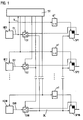
- the output signals of the Hall elements HE1 - HE18 each fed to a switch S1 - S18, through which the output signals D1 - D18 either the input of memory modules SP1 - SP18 can be fed in or directly as output signals from the encoder to be provided. How many switches are to be provided depends on of the maximum speed V of the position change, that is the maximum Speed of the encoder, and the processing speed of the modules used.
- Each Hall element HE1 - HE18 is connected to a control line with a Control unit ST connected, which thereby each individual Hall element HE1 - HE18 can switch on and off. It is obvious that an off or deactivated Hall element has no current consumption and thus the power requirement is reduced by deactivating Hall elements becomes.
- Switches S1 - S18 are also connected to the Control unit ST connected and are switched by this. Farther are the memory modules SP1 - SP18 via one control line each directly connected to the control unit ST, or it becomes the control signal for the memory modules SP1 - SP18 from the control signal of the associated Hall elements HE1 - HE18 by a time delay ⁇ t generated.
- control unit ST of the encoder to the supply voltage was connected, the control unit ST determined by querying each Hall element HE1 - HE18 in a specific, stored order the absolute position of the encoder.
- the control unit ST deactivates via the respective control lines the Hall elements HE2 - HE18 and activates the Hall element HE1. This happens at time t1, as can be seen in FIG. 3a, where the Control signals from the control unit ST for the Hall elements HE1-HE4 via the time are plotted.
- the switches S1 - S18 are first switched by the control unit ST in such a way that that the output signals D1 - D18 of the Hall elements HE1 - HE18 to the memory modules SP1 - SP18.
- control unit ST repeats this process for the next one Hall element HE2. This is done by the control unit ST at time t2 is activated and the assigned memory module SP2 is delayed also activated. Then the output signal D2 of the Hall element HE2 stored in the memory module SP2 and that Hall element HE2 is deactivated by control unit ST at time t3. This process is repeated until the output signals of all Hall elements HE1 - HE18 in the respectively assigned memory module SP1 - SP18 have been saved.
- the memory modules SP1 - SP18 are advantageously carried out as flip-flops, which the stored bit do not change until reactivation and as the output signal of the Provide the encoder in parallel form.
- the absolute Position determination also the number of revolutions of the optical division be counted by the control unit ST.
- Another alternative is to close the next Hall element already to activate a time t2 before the previous Hall element HE1 was deactivated at time t3, as shown in FIG. 3b. Thereby the Hall elements and assigned memory modules are successively activated, it is not waited until the previously activated Hall element was deactivated, so that several Hall elements with associated memory modules activated overlapping in time. This allows any Compromise between processing speed and low Achieve power consumption, depending on how many Hall elements at the same time are activated. This alternative is also for every combination of Hall element and memory module to provide a separate data line.
- control unit ST fed a signal indicating the speed V of the position change, the angular velocity for a rotary encoder, quantified.
- This signal can be, for example, the output signal D1 of the first Hall element Be HE1.
- the control unit ST compares whether the speed V of the position change is greater than a first threshold value Vmax1. If so is, the control unit ST sends a control signal to the switch S1 output, which switches the switch S1, whereby the memory module SP1 is bridged. It then becomes the output signal D1 of the Hall element HE1 is output without intermediate storage. It can be connected to the memory module SP1, which is now not required Control unit ST a signal for their deactivation are output.
- the first threshold value Vmax1 is selected such that at its Exceed the speed V of the position change is so great that intermediate storage is no longer necessary because of the output signal D1 is permanently present.
- the first threshold value Vmax1 has been exceeded, a check is carried out to determine whether a second threshold value Vmax2 is also exceeded. If that is the case the second switch S2 is also switched over, as a result of which the memory module SP2 is bridged. The output signal then also becomes immediate D2 of the Hall element HE2 is output without intermediate storage. It can also be connected to the SP2 memory module, which is now not required the control unit ST outputs a signal to deactivate it will.
- the second threshold Vmax2 becomes similar to the first Threshold value Vmax1 selected so that when it is exceeded, the speed V of the change in position is so large that an intermediate storage is no longer required because the output signal D1 is permanent is present. As a rule, the second threshold value Vmax2 becomes twice as large be like the first threshold Vmax1 because of the change in the magnetic field at the Hall element HE1 has twice the frequency as the change in Magnetic field at the Hall element HE2.
- This process of switching the output signals from Hall elements can be performed for all Hall elements HE1 to HE18 that are due to the maximum speed provided for the encoder is practical permanently output an output signal and therefore no intermediate storage is required.
- the other required threshold values Vmax3, Vmax4, etc. become twice as much according to the example above large as the previous threshold value selected.
- a further advantageous embodiment consists in providing a plurality of magnetic divisions T, as a result of which the resolution and / or value range of the rotary encoder can be expanded by a factor of 2 for each additional division track.
- the rotary movement is reduced by a gear according to the number of graduation tracks present or, if appropriate, also translated if the graduation is arranged accordingly.
- the speed must be passed on to the next graduation T, reduced by a factor of 2, for each graduation track using a digital code. If four division tracks TS1-TS4 are provided on a first division T, the rotational movement of this first division T for a second division T must be reduced by a factor of 2 4 .
- the frequency with which the individual Hall elements HE1 - HE18 are activated output signals are selected depending on the frequency. Since the output signal of the Hall element HE1 has the greatest frequency, it is activated most often and therefore occurs in the order of Hall elements activated essentially sequentially by the control unit ST most often on.
- the output signal of the Hall element HE2 points half the frequency of the output signal of the Hall element HE 1 on and therefore occurs in order only half as often as the Hall element HE1. The same applies to the other Hall elements. With the additional condition, that two activations of the same Hall element HE1 - HE18 should always be at the same time interval from each other the order in which the control unit ST the individual Hall elements HE1 - HE18 activated.
Abstract
Description
Die Erfindung betrifft ein Verfahren zum Betrieb eines Positionsgebers, vorzugsweise
eines Drehgebers, der Hall-Elemente aufweist, nach dem Oberbegriff
des Anspruchs 1 und einen Positionsgeber gemäß dem Oberbegriff
von Anspruch 10 zur Durchführung des Verfahrens.The invention relates to a method for operating a position transmitter, preferably
a rotary encoder that has Hall elements, according to the preamble
of
Aus dem Stand der Technik sind bereits seit langem Drehgeber bekannt, die eine magnetische Teilung mit einer Codestruktur aufweisen. Gemäß der DE 44 42 371 A1 der Anmelderin zeichnen sich derartige Teilungen durch eine mehrspurige alternierende Magnetisierung eines rotationssymmetrischen Körpers aus, der sich proportional der dem Drehgeber zugeführten Drehbewegung dreht. Diese alternierende Magnetisierung wird bei einer Drehbewegung durch statische Hall-Elemente für jede Spur der Teilung detektiert und als absolutes Positionssignal ausgegeben. Encoders have long been known from the prior art have a magnetic division with a code structure. According to the DE 44 42 371 A1 of the applicant are characterized by such divisions multi-track alternating magnetization of a rotationally symmetric Body, which is proportional to that supplied to the encoder Rotary motion rotates. This alternating magnetization is with a Rotational movement detected by static Hall elements for each track of the division and output as an absolute position signal.
Aus der EP 0 331 828 A1 ist ein Multiturngeber bekannt, der sich im Prinzip aus zwei Meßsystemen zusammensetzt. Es wird durch ein inkrementales optisches Meßsystem die genaue Position im Bereich von einer 360°-Drehung der optischen Teilung bestimmt und zusätzlich die Anzahl der Umdrehungen der optischen Teilung mit Hilfe eines magnetischen Detektors ermittelt. Daraus kann dann eine Steuereinheit die absolute Position auch bei mehreren Umdrehungen des Drehgebers ermitteln. Wird der Multiturngeber mit der Versorgungsspannung verbunden, wird die gespeicherte Anzahl Umdrehungen und der gespeicherte Inkrementalwert ausgegeben. Um den Verbrauch an elektrischer Leistung zu reduzieren, werden magnetoresistive Elemente mit einigen Hundert Kiloohm Innenwiderstand verwendet und zusätzliche Widerstände in Reihe geschaltet. Weiterhin werden digitale Baugruppen, die in CMOS-Technologie gefertigt wurden, verwendet.A multi-turn transmitter is known from EP 0 331 828 A1, which in principle composed of two measuring systems. It is incremental optical measuring system the exact position in the range of a 360 ° rotation the optical division and also the number of revolutions the optical division with the help of a magnetic detector. From this, a control unit can also determine the absolute position several revolutions of the encoder. Becomes the multiturn encoder the stored number is connected to the supply voltage Revolutions and the stored incremental value. To the Reducing electrical power consumption will be magnetoresistive Elements with a few hundred kiloohms internal resistance are used and additional ones Resistors connected in series. Furthermore, digital assemblies, which were manufactured in CMOS technology.
Dabei ist von Nachteil, daß der Bedarf an elektrischer Leistung von CMOS-Baugruppen proportional mit der Frequenz steigt, so daß bei einer hohen Verarbeitungsgeschwindigkeit auch der Bedarf an elektrischer Leistung groß ist. Weiterhin sind spezielle magnetoresistive Elemente mit einem hohen Innenwiderstand erforderlich, die eine aufwendige Weiterverarbeitung ihres Ausgangssignals notwendig machen, was zu einer erhöhten Störempfindlichkeit führt.The disadvantage here is that the electrical power requirement of CMOS modules increases proportionally with frequency, so at a high Processing speed, the need for electrical power is great is. Furthermore, special magnetoresistive elements with a high Internal resistance is required, which requires extensive processing of your Output signal necessary, resulting in increased sensitivity to interference leads.
Aus der EP 0 158 781 A1 ist ein inkrementaler Drehgeber bekannt, bei dem mit einem optischen Meßsystem die Position bzw. der Drehwinkel bestimmt wird. Das optische Meßsystem weist dabei eine Lichtquelle, eine statische und eine rotierende Teilung sowie lichtempfindliche Baugruppen mit zugehöriger Auswerteelektronik auf. Zur Energieeinsparung werden die Lichtquelle und die Auswerteelektronik nur so lange mit der Versorgungsspannung verbunden, wie zur Feststellung der Position innerhalb der kleinsten Teilungsperiode benötigt wird. In der übrigen Zeit werden diese Baugruppen von der Energieversorgung getrennt. An incremental rotary encoder is known from EP 0 158 781 A1, in which the position or the angle of rotation is determined using an optical measuring system becomes. The optical measuring system has a light source, a static one and a rotating division and photosensitive assemblies with associated Evaluation electronics. To save energy, the light source and the evaluation electronics are only connected to the supply voltage for as long as as for determining the position within the smallest division period is needed. In the rest of the time, these modules are used by Separate energy supply.
Dabei ist von Nachteil, daß bei Verwendung eines magnetischen Detektorsystems aufgrund der dafür erforderlichen wesentlich größeren Stromstärken in der gesamten Schaltungsanordnung bei einer nur kurzzeitigen Verbindung der Lichtquelle und der Auswerteelektronik mit der Versorgungsspannung Störungen auftreten.The disadvantage here is that when using a magnetic detector system due to the much larger currents required for this in the entire circuit arrangement with a short-term connection the light source and the evaluation electronics with the supply voltage Disturbances occur.
Der Erfindung liegt daher die Aufgabe zugrunde, einen Positionsgeber mit magnetischem Meßsystem derart auszugestalten und ein Verfahren zu dessen Betrieb anzugeben, daß der Bedarf an elektrischer Leistung wesentlich reduziert wird, wobei sichergestellt sein muß, daß dadurch keine Störungen verursacht werden.The invention is therefore based on the object of having a position sensor Magnetic measuring system to design and a method for it Operation indicate that the need for electrical power is essential is reduced, it must be ensured that no interference caused.
Diese Aufgabe wird durch die Merkmale der unabhängigen Ansprüche 1 und
10 gelöst.This object is achieved by the features of
Den abhängigen Ansprüchen sind weitere vorteilhafte Ausgestaltungen zu entnehmen.The dependent claims provide further advantageous refinements remove.
Das erfindungsgemäße Verfahren zum Betrieb eines Positionsgebers weist den Vorteil auf, daß die zur Detektion einer Position vorgesehenen Hall-Elemente nicht gleichzeitig, sondern in einer bestimmten Reihenfolge nacheinander eingeschaltet, abgefragt und wieder ausgeschaltet werden. Da der maximale Strombedarf der gesamten Schaltungsanordnung im wesentlichen durch den Strombedarf der Hall-Elemente bestimmt wird, kann durch die sequentielle Abfrage der einzelnen Hall-Elemente der maximale Strombedarf wesentlich verringert werden.The method according to the invention for operating a position transmitter has the advantage that the Hall elements provided for the detection of a position not at the same time, but in a certain order one after the other switched on, queried and switched off again. Since the maximum current consumption of the entire circuit arrangement essentially determined by the current requirements of the Hall elements can be determined by the sequential query of the individual Hall elements of the maximum power requirement be significantly reduced.
Weiterhin werden nur eine kleine Anzahl Hall-Elemente gleichzeitig geschaltet, wodurch die durch den Schaltvorgang bedingten Störungen im elektrischen Leitungsnetz praktisch nicht mehr auftreten. Weiterhin von Vorteil ist die zeitverzögerte Speicherung des Ausgangssignals eines jeden Hall-Elements, wodurch Störungen, welche in einer Stabilisierungsphase der Hall-Elemente auftreten, unterdrückt werden. Der erfindungsgemäße Positionsgeber weist den Vorteil auf, daß einzelne Hall-Elemente über eine individuelle Steuerleitung von einer Steuereinheit aktiviert und deaktiviert werden können. Weiterhin kann jede Speicherbaugruppe separat von der Steuereinheit angesteuert werden.Furthermore, only a small number of Hall elements are switched at the same time, whereby the interference caused by the switching process electrical line network practically no longer occur. Continue from The advantage is the time-delayed storage of the output signal of everyone Hall elements, which causes disturbances in a stabilization phase of the Hall elements occur, are suppressed. The position transmitter according to the invention has the advantage that individual Hall elements over an individual Control line can be activated and deactivated by a control unit can. Furthermore, each memory module can be separate from the control unit can be controlled.
Das erfindungsgemäße Verfahren und der erfindungsgemäße Positionsgeber sollen nun anhand der Zeichnungen näher beschrieben und erläutert werden. Es zeigen:
- Fig. 1:
- eine mögliche schaltungstechnische Realisierung des erfindungsgemäßen Positionsgebers,
- Fig. 2:
- eine mögliche Realisierung einer magnetischen Teilung mit Codestruktur,
- Fig. 3a:
- ein möglicher Verlauf von Steuersignalen für die Hall-Elemente,
- Fig. 3b:
- ein weiterer möglicher Verlauf von Steuersignalen für Hall-Elemente und
- Fig. 4:
- ein mögliches Verlauf von geschwindigkeitsabhängigen Steuersignalen zur Abschaltung einzelner Hall-Element.
- Fig. 1:
- a possible circuitry implementation of the position sensor according to the invention,
- Fig. 2:
- a possible realization of a magnetic division with code structure,
- Fig. 3a:
- a possible course of control signals for the Hall elements,
- 3b:
- another possible course of control signals for Hall elements and
- Fig. 4:
- a possible course of speed-dependent control signals for switching off individual Hall elements.
Das erfindungsgemäße Verfahren und der erfindungsgemäße Positionsgeber sollen beispielhaft an einem Multiturn-Drehgeber erläutert werden, der unmittelbar einen parallelen Code ausgibt und neben mindestens einer magnetischen Teilung mit Codestruktur auch mindestens eine optische Teilung aufweist, die sowohl eine Codestruktur als auch eine inkrementale Struktur aufweisen kann. Es ist jedoch für den Fachmann offensichtlich, daß das erfindungsgemäße Verfahren ebenso bei Positionsgebern für Längenmeßsysteme, bei Singleturn-Drehgebern oder bei Meßsystemen, die einen inkrementalen Wert ausgeben, eingesetzt werden kann. The method according to the invention and the position transmitter according to the invention are to be explained using a multiturn encoder as an example immediately outputs a parallel code and next to at least one magnetic one Division with code structure also at least one optical division has both a code structure and an incremental structure can have. However, it will be apparent to those skilled in the art that the invention The same applies to position encoders for length measuring systems, with single-turn encoders or with measuring systems that have an incremental Output value that can be used.
Die zu messende Drehbewegung wird in einem ersten Schritt auf eine optische Teilung des Drehgebers übertragen, welche mehrere Teilungsspuren aufweist, die gemäß einem Code ausgebildet sind. Dadurch werden die niederwertigsten Bits des Ausgangssignals des Drehgebers erzeugt. Durch die optische Teilung wird somit ein Singleturn-Drehgeber mit beispielsweise sechs Bit Auflösung realisiert.In a first step, the rotary movement to be measured is based on an optical one Transfer the encoder encoder, which has multiple graduation tracks has, which are designed according to a code. This will make the least significant Bits of the encoder output signal are generated. Through the Optical division is thus a single-turn encoder, for example six bit resolution realized.
Anschließend wird die Drehbewegung der optischen Teilung durch ein Getriebe um den Faktor 1:26 untersetzt und einer magnetischen Teilung T zugeleitet, die in Fig. 2 dargestellt ist. Das Untersetzungsverhältnis entspricht dabei der Auflösung der optischen Teilung, so daß das höchstwertige Bit der optischen Teilung die halbe Wertigkeit des niederwertigsten Bits der magnetischen Teilung T aufweist. Die magnetische Teilung T wird in der Regel prinzipiell identisch der optischen Teilung, gemäß einem digitalen Code, z.B. dem Gray-Code, ausgestaltet.The rotary movement of the optical graduation is then reduced by a factor of 1: 2 6 by a gear and fed to a magnetic graduation T, which is shown in FIG. 2. The reduction ratio corresponds to the resolution of the optical division, so that the most significant bit of the optical division has half the value of the least significant bit of the magnetic division T. In principle, the magnetic division T is basically identical to the optical division, in accordance with a digital code, for example the Gray code.
Unmittelbar über den einzelnen Teilungsspuren TS1 bis TS4 der magnetischen Teilung T sind Hall-Elemente statisch angeordnet, die detektieren, welche Magnetisierung die darunterliegende Teilungsspur gerade aufweist. Die Hall-Elemente geben ein Ausgangssignal aus, welches entsprechend der Magnetisierung der Teilungsspur zwei Zustände aufweist. Da die Teilungsperioden der Teilungsspuren TS1 - TS4 sich immer um den Faktor 2 unterscheiden, unterscheidet sich auch die Wertigkeit der Ausgangssignale der Hall-Elemente, entsprechend der Teilungsperiode, um der Faktor 2. Die Hall-Elemente sind derart über den einzelnen Teilungsspuren TS1 - TS4 angeordnet, daß das Ausgangssignal des Hall-Elements HE1 die niedrigste Wertigkeit aufweist, da es über der Teilungsspur TS1 mit der kürzesten Teilungsperiode angeordnet ist. Die Numerierung der Hall-Elemente wurde so gewählt, daß die Wertigkeit des Ausgangssignals des Hall-Elements durch dessen Nummer zum Ausdruck kommt, so daß das Ausgangssignal mit der höchsten Wertigkeit vom Hall-Element HE18 ausgegeben wird. Immediately above the individual graduation tracks TS1 to TS4 of the magnetic Graduation T, Hall elements are arranged statically, which detect what magnetization the graduation track below has. The Hall elements output an output signal, which accordingly the magnetization of the graduation track has two states. Because the division periods the division tracks TS1 - TS4 are always by a factor of 2 differ, the value of the output signals also differs of the Hall elements, corresponding to the division period, by a factor of 2. The Hall elements are above the individual graduation tracks TS1 - TS4 arranged that the output signal of the Hall element HE1 the lowest Has value, since it has the shortest track over the division track TS1 Division period is arranged. The Hall elements were numbered chosen so that the value of the output signal of the Hall element is expressed by its number, so that the output signal with the highest value is output by the Hall element HE18.
Wie in Fig. 1 dargestellt, werden die Ausgangssignale der Hall-Elemente HE1 - HE18 jeweils einem Schalter S1 - S18 zugeleitet, durch den die Ausgangssignale D1 - D18 entweder dem Eingang von Speicherbaugruppen SP1 - SP18 zugeleitet werden oder direkt als Ausgangssignale des Drehgebers bereitgestellt werden. Wie viele Schalter vorzusehen sind, ist abhängig von der maximalen Geschwindigkeit V der Positionsänderung, also der maximalen Drehzahl der Drehgebers, und der Verarbeitungsgeschwindigkeit der verwendeten Baugruppen.As shown in Fig. 1, the output signals of the Hall elements HE1 - HE18 each fed to a switch S1 - S18, through which the output signals D1 - D18 either the input of memory modules SP1 - SP18 can be fed in or directly as output signals from the encoder to be provided. How many switches are to be provided depends on of the maximum speed V of the position change, that is the maximum Speed of the encoder, and the processing speed of the modules used.
Jedes Hall-Element HE1 - HE18 wird über eine Steuerleitung mit einer Steuereinheit ST verbunden, die dadurch jedes einzelne Hall-Element HE1 - HE18 ein- und ausschalten kann. Es liegt auf der Hand, daß ein ausgeschaltetes bzw. deaktiviertes Hall-Element keine Stromaufnahme aufweist und somit der Strombedarf durch das Deaktivieren von Hall-Elementen verringert wird. Auch die Schalter S1 - S18 sind über Steuerleitungen mit der Steuereinheit ST verbunden und werden von dieser umgeschaltet. Weiterhin sind die Speicherbaugruppen SP1 - SP18 über je eine Steuerleitung entweder direkt mit der Steuereinheit ST verbunden, oder es wird das Steuersignal für die Speicherbaugruppen SP1 - SP18 aus dem Steuersignal des jeweils zugeordneten Hall-Elements HE1 - HE18 durch eine Zeitverzögerung Δt erzeugt.Each Hall element HE1 - HE18 is connected to a control line with a Control unit ST connected, which thereby each individual Hall element HE1 - HE18 can switch on and off. It is obvious that an off or deactivated Hall element has no current consumption and thus the power requirement is reduced by deactivating Hall elements becomes. Switches S1 - S18 are also connected to the Control unit ST connected and are switched by this. Farther are the memory modules SP1 - SP18 via one control line each directly connected to the control unit ST, or it becomes the control signal for the memory modules SP1 - SP18 from the control signal of the associated Hall elements HE1 - HE18 by a time delay Δt generated.
Im folgenden soll die Arbeitsweise des erfindungsgemäßen Drehgebers erläutert werden. Nachdem die Steuereinheit ST des Drehgebers an die Versorgungsspannung angeschlossen wurde, ermittelte die Steuereinheit ST durch Abfrage eines jeden Hall-Elements HE1 - HE18 in einer bestimmten, gespeicherten Reihenfolge die absolute Position des Drehgebers.The mode of operation of the rotary encoder according to the invention is explained below will. After the control unit ST of the encoder to the supply voltage was connected, the control unit ST determined by querying each Hall element HE1 - HE18 in a specific, stored order the absolute position of the encoder.
Hierfür deaktiviert die Steuereinheit ST über die jeweiligen Steuerleitungen die Hall-Elemente HE2 - HE18 und aktiviert das Hall-Element HE1. Dies geschieht zum Zeitpunkt t1, wie Fig. 3a zu entnehmen ist, wo exemplarisch die Steuersignale der Steuereinheit ST für die Hall-Elemente HE1 - HE4 über der Zeit aufgetragen sind. Durch die Deaktivierung wird der Strombedarf der gesamten Schaltungsanordnung, der wesentlich durch den Strombedarf der Hall-Elemente HE1 - HE18 bestimmt wird, drastisch verringert. Weiterhin werden durch die Steuereinheit ST die Schalter S1 - S18 zunächst so geschaltet, daß die Ausgangssignale D1 - D18 der Hall-Elemente HE1 - HE18 den Speicherbaugruppen SP1 - SP18 zugeleitet werden. Dabei wird davon ausgegangen, daß die Geschwindigkeit der Positionsänderung nicht über einem Schwellwert liegt. Nach einer bestimmten Zeit, die erforderlich ist, damit am Eingang der Speicherbaugruppe SP1 ein stabiles Ausgangssignal D1 des Hall-Elements HE1 vorliegt, wird vorzugsweise über die Zeitverzögerung Δt oder über eine separate Steuerleitung der Steuereinheit ST die dem Hall-Element HE1 zugeordnete Speicherbaugruppe SP1 angesteuert, um das Ausgangssignal D1 des Hall-Elements HE1 zu speichern. Das Ausgangssignal D1 wird dabei über die Datenleitung DL übertragen. Danach wird das Hall-Element HE1 durch die Steuereinheit ST zum Zeitpunkt t2 deaktiviert, wie Fig. 3a zu entnehmen ist, wodurch diese Baugruppe keinen Strom mehr benötigt.For this purpose, the control unit ST deactivates via the respective control lines the Hall elements HE2 - HE18 and activates the Hall element HE1. this happens at time t1, as can be seen in FIG. 3a, where the Control signals from the control unit ST for the Hall elements HE1-HE4 via the time are plotted. By deactivating the power consumption of the entire circuit arrangement, which is essentially determined by the current requirements of the Hall elements HE1 - HE18 is determined, drastically reduced. Farther the switches S1 - S18 are first switched by the control unit ST in such a way that that the output signals D1 - D18 of the Hall elements HE1 - HE18 to the memory modules SP1 - SP18. In doing so assumed that the speed of the position change does not exceed a threshold. After a certain amount of time that is required thus a stable output signal at the input of the memory module SP1 D1 of the Hall element HE1 is present, is preferably via the time delay Δt or via a separate control line of the control unit ST Hall element HE1 assigned to memory module SP1 to save the output signal D1 of the Hall element HE1. The output signal D1 is transmitted over the data line DL. After that Hall element HE1 is deactivated by control unit ST at time t2, As can be seen in FIG. 3a, which means that this assembly does not Electricity needed more.
Danach wiederholt die Steuereinheit ST diesen Vorgang für das nächste Hall-Element HE2. Dieses wird zum Zeitpunkt t2 von der Steuereinheit ST aktiviert und die zugeordnete Speicherbaugruppe SP2 wird mit einer Zeitverzögerung ebenfalls aktiviert. Anschließend wird das Ausgangssignal D2 des Hall-Elements HE2 in der Speicherbaugruppe SP2 gespeichert und das Hall-Element HE2 wird zum Zeitpunkt t3 von der Steuereinheit ST deaktiviert. Dieser Vorgang wiederholt sich so oft, bis die Ausgangssignale aller Hall-Elemente HE1 - HE18 in der jeweils zugeordneten Speicherbaugruppe SP1 - SP18 gespeichert wurden. Die Speicherbaugruppen SP1 - SP18 werden dabei vorteilhaft als Flip-Flops ausgeführt, welche das gespeicherte Bit bis zu einer erneuten Aktivierung nicht ändern und als Ausgangssignal des Drehgebers in paralleler Form bereitstellen. Then the control unit ST repeats this process for the next one Hall element HE2. This is done by the control unit ST at time t2 is activated and the assigned memory module SP2 is delayed also activated. Then the output signal D2 of the Hall element HE2 stored in the memory module SP2 and that Hall element HE2 is deactivated by control unit ST at time t3. This process is repeated until the output signals of all Hall elements HE1 - HE18 in the respectively assigned memory module SP1 - SP18 have been saved. The memory modules SP1 - SP18 are advantageously carried out as flip-flops, which the stored bit do not change until reactivation and as the output signal of the Provide the encoder in parallel form.
Da zusätzlich eine optische Teilung vorgesehen ist, die eine wesentlich höhere Auflösung aufweist, besteht auch die Möglichkeit, daß die Positionsbestimmung mit Hilfe der Hall-Elemente nur dann erfolgt, wenn die absolute Position ermittelt werden muß, beispielsweise wenn der Drehgeber eingeschaltet wird oder daß die Hall-Elemente nur in bestimmten Zeitintervallen zur Positionsbestimmung benutzt werden. Im Dauerbetrieb kann zur absoluten Positionsbestimmung auch die Umdrehungszahl der optischen Teilung von der Steuereinheit ST mitgezählt werden.Since an optical division is also provided, which is much higher Has resolution, there is also the possibility that the position determination with the help of the Hall elements only when the absolute Position must be determined, for example when the encoder is switched on or that the Hall elements only in certain time intervals be used to determine the position. In continuous operation, the absolute Position determination also the number of revolutions of the optical division be counted by the control unit ST.
Alternativ besteht die Möglichkeit, daß nicht, wie oben beschrieben, immer nur ein Hall-Element nach dem anderen Hall-Element zu den Zeitpunkten t1, t2, t3 usw. aktiviert wird, wodurch immer nur ein einziges Hall-Element gleichzeitig aktiviert ist, sondern daß mehrere Hall-Elemente gleichzeitig aktiviert werden. Dabei ist jedoch zu beachten, daß dann nicht mehr nur eine einzige Datenleitung DL zwischen Hall-Elementen HE1 - HE18 und Speicherbaugruppen SP1 - SP18 erforderlich ist, sondern für jede Kombination aus Hall-Element und zugeordneter Speicherbaugruppe eine separate Datenleitung vorzusehen ist.Alternatively, there is a possibility that not always, as described above only one Hall element after the other Hall element at times t1, t2, t3 etc. is activated, whereby only one Hall element at a time is activated at the same time, but that several Hall elements are activated simultaneously will. It should be noted, however, that then no longer just one only data line DL between Hall elements HE1-HE18 and memory modules SP1 - SP18 is required, but for each combination a separate data line consisting of the Hall element and the assigned memory module is to be provided.
Ein weitere Alternative besteht darin, das nächste Hall-Element bereits zu einem Zeitpunkt t2 zu aktivieren, bevor das vorhergehende Hall-Element HE1 zum Zeitpunkt t3 deaktiviert wurde, wie in Fig. 3b dargestellt. Dadurch werden die Hall-Elemente und zugeordneten Speicherbaugruppen nacheinander aktiviert, es wird nicht gewartet, bis das vorher aktivierte Hall-Element deaktiviert wurde, so daß mehrere Hall-Elemente mit zugehöriger Speicherbaugruppe zeitlich überlappend aktiviert sind. Dadurch läßt sich ein beliebiger Kompromiß zwischen Verarbeitungsgeschwindigkeit und niedrigem Stromverbrauch erreichen, je nachdem wieviele Hall-Elemente gleichzeitig aktiviert sind. Auch bei dieser Alternative ist für jede Kombination aus Hall-Element und Speicherbaugruppe eine separate Datenleitung vorzusehen. Another alternative is to close the next Hall element already to activate a time t2 before the previous Hall element HE1 was deactivated at time t3, as shown in FIG. 3b. Thereby the Hall elements and assigned memory modules are successively activated, it is not waited until the previously activated Hall element was deactivated, so that several Hall elements with associated memory modules activated overlapping in time. This allows any Compromise between processing speed and low Achieve power consumption, depending on how many Hall elements at the same time are activated. This alternative is also for every combination of Hall element and memory module to provide a separate data line.
In einer möglichen vorteilhaften Ausgestaltung der Erfindung wird der Steuereinheit ST ein Signal zugeleitet, das die Geschwindigkeit V der Positionsänderung, bei einem Drehgeber die Winkelgeschwindigkeit, quantifiziert. Dieses Signal kann beispielsweise das Ausgangssignal D1 des ersten Hall-Elements HE1 sein.In a possible advantageous embodiment of the invention, the control unit ST fed a signal indicating the speed V of the position change, the angular velocity for a rotary encoder, quantified. This signal can be, for example, the output signal D1 of the first Hall element Be HE1.
Die Steuereinheit ST vergleicht dann, ob die Geschwindigkeit V der Positionsänderung größer einem ersten Schwellwert Vmax1 ist. Falls dies der Fall ist, wird durch die Steuereinheit ST an den Schalter S1 ein Steuersignal ausgegeben, das den Schalter S1 umschaltet, wodurch die Speicherbaugruppe SP1 überbrückt wird. Es wird dann unmittelbar das Ausgangssignal D1 des Hall-Elements HE1 ohne Zwischenspeicherung ausgegeben. Es kann an die Speicherbaugruppe SP1, die nun nicht benötigt wird, von der Steuereinheit ST ein Signal zu deren Deaktivierung ausgegeben werden. Dabei wird der erste Schwellwert Vmax1 derart gewählt, daß bei dessen Überschreiten die Geschwindigkeit V der Positionsänderung so groß ist, daß eine Zwischenspeicherung nicht mehr erforderlich ist, weil das Ausgangssignal D1 permanent vorliegt.The control unit ST then compares whether the speed V of the position change is greater than a first threshold value Vmax1. If so is, the control unit ST sends a control signal to the switch S1 output, which switches the switch S1, whereby the memory module SP1 is bridged. It then becomes the output signal D1 of the Hall element HE1 is output without intermediate storage. It can be connected to the memory module SP1, which is now not required Control unit ST a signal for their deactivation are output. The first threshold value Vmax1 is selected such that at its Exceed the speed V of the position change is so great that intermediate storage is no longer necessary because of the output signal D1 is permanently present.
Falls der erste Schwellwert Vmax1 überschritten wurde, wird geprüft, ob auch ein zweiter Schwellwert Vmax2 überschritten wird. Ist das der Fall, so wird auch der zweite Schalter S2 umgeschaltet, wodurch die Speicherbaugruppe SP2 überbrückt wird. Es wird dann unmittelbar auch das Ausgangssignal D2 des Hall-Elements HE2 ohne Zwischenspeicherung ausgegeben. Es kann auch an die Speicherbaugruppe SP2, die nun nicht benötigt wird, durch die Steuereinheit ST ein Signal zu deren Deaktivierung ausgegeben werden. Dabei wird der zweite Schwellwert Vmax2 ähnlich dem ersten Schwellwert Vmax1 so gewählt, daß bei dessen Überschreiten die Geschwindigkeit V der Positionsänderung so groß ist, daß eine Zwischenspeicherung nicht mehr erforderlich ist, weil das Ausgangssignal D1 permanent vorliegt. In der Regel wird der zweite Schwellwert Vmax2 doppelt so groß sein wie der erste Schwellwert Vmax1, da die Änderung des Magnetfeldes am Hall-Element HE1 die doppelte Frequenz aufweist wie die Änderung des Magnetfeldes am Hall-Element HE2.If the first threshold value Vmax1 has been exceeded, a check is carried out to determine whether a second threshold value Vmax2 is also exceeded. If that is the case the second switch S2 is also switched over, as a result of which the memory module SP2 is bridged. The output signal then also becomes immediate D2 of the Hall element HE2 is output without intermediate storage. It can also be connected to the SP2 memory module, which is now not required the control unit ST outputs a signal to deactivate it will. The second threshold Vmax2 becomes similar to the first Threshold value Vmax1 selected so that when it is exceeded, the speed V of the change in position is so large that an intermediate storage is no longer required because the output signal D1 is permanent is present. As a rule, the second threshold value Vmax2 becomes twice as large be like the first threshold Vmax1 because of the change in the magnetic field at the Hall element HE1 has twice the frequency as the change in Magnetic field at the Hall element HE2.
Dieser Vorgang der Umschaltung der Ausgangssignale von Hall-Elementen kann für alle Hall-Elemente HE1 bis HE18 durchgeführt werden, die aufgrund der für den Drehgeber vorgesehenen Maximaldrehzahl praktisch permanent ein Ausgangssignal ausgeben und für die daher keine Zwischenspeicherung erforderlich ist. Die weiteren erforderlichen Schwellwerte Vmax3, Vmax4, usw. werden entsprechend dem obigen Beispiel doppelt so groß wie der jeweils vorhergehende Schwellwert gewählt.This process of switching the output signals from Hall elements can be performed for all Hall elements HE1 to HE18 that are due to the maximum speed provided for the encoder is practical permanently output an output signal and therefore no intermediate storage is required. The other required threshold values Vmax3, Vmax4, etc. become twice as much according to the example above large as the previous threshold value selected.
Unmittelbar nach Unterschreiten eines der Schwellwerte für die Geschwindigkeit der Positionsänderung wird der dem jeweiligen Schwellwert zugeordnete Schalter wieder umgeschaltet und die zugeordnete Speicherbaugruppe wieder aktiviert.Immediately after falling below one of the threshold values for the speed the change in position is assigned to the respective threshold value Switch switched again and the assigned memory module reactivated.
Eine weitere vorteilhafte Ausgestaltung besteht darin, mehrere magnetische Teilungen T vorzusehen, wodurch Auflösung und/oder Wertebereich des Drehgebers für jede zusätzliche Teilungsspur um den Faktor 2 erweitert werden können. Dabei wird die Drehbewegung entsprechend der Anzahl vorhandener Teilungsspuren über ein Getriebe untersetzt oder bei einer entsprechenden Anordnung der Teilungen gegebenenfalls auch übersetzt. Wie bereits bei der Kopplung zwischen optischer und magnetischer Teilung T beschrieben, muß für jede Teilungsspur mit einem digitalen Code die Drehzahl um den Faktor 2 untersetzt an den nächste Teilung T weitergeleitet werden. Sind also auf einer ersten Teilung T vier Teilungsspuren TS1 - TS4 vorgesehen, muß die Drehbewegung dieser ersten Teilung T für eine zweite Teilung T mit dem Faktor 24 untersetzt werden.A further advantageous embodiment consists in providing a plurality of magnetic divisions T, as a result of which the resolution and / or value range of the rotary encoder can be expanded by a factor of 2 for each additional division track. In this case, the rotary movement is reduced by a gear according to the number of graduation tracks present or, if appropriate, also translated if the graduation is arranged accordingly. As already described for the coupling between the optical and magnetic graduation T, the speed must be passed on to the next graduation T, reduced by a factor of 2, for each graduation track using a digital code. If four division tracks TS1-TS4 are provided on a first division T, the rotational movement of this first division T for a second division T must be reduced by a factor of 2 4 .
Die Häufigkeit, mit der die einzelnen Hall-Elemente HE1 - HE18 aktiviert werden, wird abhängig von der Frequenz deren Ausgangssignale gewählt. Da das Ausgangssignal des Hall-Elements HE1 die größte Frequenz aufweist, wird es am häufigsten aktiviert und tritt daher in der Reihenfolge der von der Steuereinheit ST im wesentlichen sequentiell aktivierten Hall-Elemente am häufigsten auf. Das Ausgangssignal des Hall-Elements HE2 weist die halbe Frequenz des Ausgangssignals des Hall-Elements HE 1 auf und tritt daher in der Reihenfolge nur halb so häufig auf wie das Hall-Element HE1. Für die weiteren Hall-Elemente gilt entsprechendes. Mit der Zusatzbedingung, daß zwei Aktivierungen ein und desselben Hall-Elements HE1 - HE18 möglichst immer den gleichen zeitlichen Abstand voneinander haben sollen, wird eindeutig die Reihenfolge definiert, in der die Steuereinheit ST die einzelnen Hall-Elemente HE1 - HE18 aktiviert.The frequency with which the individual Hall elements HE1 - HE18 are activated output signals are selected depending on the frequency. Since the output signal of the Hall element HE1 has the greatest frequency, it is activated most often and therefore occurs in the order of Hall elements activated essentially sequentially by the control unit ST most often on. The output signal of the Hall element HE2 points half the frequency of the output signal of the Hall element HE 1 on and therefore occurs in order only half as often as the Hall element HE1. The same applies to the other Hall elements. With the additional condition, that two activations of the same Hall element HE1 - HE18 should always be at the same time interval from each other the order in which the control unit ST the individual Hall elements HE1 - HE18 activated.
Claims (20)
dadurch gekennzeichnet,
daß die Hall-Elemente (HE1 - HE18) in einer vorgegebenen Reihenfolge aktiviert und deaktiviert werden und daß eine jedem Hall-Element (HE1 - HE18) zugeordnete Baugruppe (SP1 - SP18) zur Speicherung dessen Ausgangssignals (D1 - D18) aktiviert wird.Method for operating a position encoder, in particular a rotary encoder, which has a plurality of Hall elements (HE1-HE18) which are selectively activated and deactivated,
characterized,
that the Hall elements (HE1 - HE18) are activated and deactivated in a predetermined order and that an assembly (SP1 - SP18) assigned to each Hall element (HE1 - HE18) is activated for storing its output signal (D1 - D18).
dadurch gekennzeichnet,
daß jedes Hall-Element (HE1 - HE18) über eine Datenleitung (DL) mit einer Speicherbaugruppe (SP1 - SP18) verbunden ist, daß jede Speicherbaugruppe (SP1 - SP18) über eine Steuerleitung mit der Steuereinheit (ST) verbunden ist.Position encoder, in particular rotary encoder, which has a plurality of Hall elements (HE1 - HE18) and a control unit (ST) for the selective activation and deactivation of the Hall elements (HE1 - HE18), each Hall element (HE1 - HE18) via a control line is connected to the control unit (ST),
characterized,
that each Hall element (HE1 - HE18) is connected to a memory module (SP1 - SP18) via a data line (DL), that each memory module (SP1 - SP18) is connected to the control unit (ST) via a control line.
Applications Claiming Priority (2)
| Application Number | Priority Date | Filing Date | Title |
|---|---|---|---|
| DE19709087 | 1997-03-06 | ||
| DE19709087A DE19709087A1 (en) | 1997-03-06 | 1997-03-06 | Circuit arrangement and method for operating a position transmitter with Hall elements |
Publications (2)
| Publication Number | Publication Date |
|---|---|
| EP0863384A1 true EP0863384A1 (en) | 1998-09-09 |
| EP0863384B1 EP0863384B1 (en) | 2002-11-06 |
Family
ID=7822390
Family Applications (1)
| Application Number | Title | Priority Date | Filing Date |
|---|---|---|---|
| EP98103698A Expired - Lifetime EP0863384B1 (en) | 1997-03-06 | 1998-03-03 | Circuit and method for the operation of a position sensor using Hall elements |
Country Status (5)
| Country | Link |
|---|---|
| US (1) | US6320373B1 (en) |
| EP (1) | EP0863384B1 (en) |
| JP (1) | JP4111357B2 (en) |
| AT (1) | ATE227418T1 (en) |
| DE (2) | DE19709087A1 (en) |
Cited By (4)
| Publication number | Priority date | Publication date | Assignee | Title |
|---|---|---|---|---|
| WO2001098736A1 (en) * | 2000-06-23 | 2001-12-27 | Sensirion Ag | Gas meter and method for detecting a consumed amount of gas |
| CN101443632A (en) * | 2006-05-12 | 2009-05-27 | 株式会社安川电机 | Magnetic encoder |
| CN113439198A (en) * | 2019-02-26 | 2021-09-24 | 大陆汽车有限公司 | Method for authorizing the updating of a magnetic sensor of a heat engine with immunity to magnetic interference |
| DE102011050834B4 (en) | 2011-06-03 | 2022-02-17 | Ic - Haus Gmbh | Integrated circuit arrangement with Hall sensors and position measuring device |
Families Citing this family (13)
| Publication number | Priority date | Publication date | Assignee | Title |
|---|---|---|---|---|
| DE19849108C2 (en) * | 1998-10-24 | 2001-12-13 | Fritz Kuebler Gmbh Zaehl Und S | Encoder |
| DE19915988A1 (en) | 1999-04-09 | 2000-10-12 | Pierburg Ag | Measuring device for determining the position of an actuator |
| US7317313B2 (en) * | 2002-11-14 | 2008-01-08 | Measurement Specialties, Inc. | Magnetic encoder apparatus |
| DE10311412B3 (en) * | 2003-03-13 | 2004-05-27 | Lenord, Bauer & Co. Gmbh | Absolute position measuring method for source shaft e.g. for servo drive, using evaluation unit for supplying current/voltage to sensor part for duration of measurement |
| JP2005093420A (en) * | 2003-08-08 | 2005-04-07 | Omron Corp | Input device, and electronic apparatus and cell phone using it |
| JP4553714B2 (en) * | 2004-12-14 | 2010-09-29 | Ntn株式会社 | Rotation detection device and bearing with rotation detection device |
| WO2006064687A1 (en) | 2004-12-14 | 2006-06-22 | Ntn Corporation | Rotation detecting apparatus and bearing provided with same |
| US7633177B2 (en) * | 2005-04-14 | 2009-12-15 | Natural Forces, Llc | Reduced friction wind turbine apparatus and method |
| EP2365411A1 (en) * | 2010-03-10 | 2011-09-14 | Sensirion AG | Flow control arrangement |
| US20120242320A1 (en) * | 2011-03-22 | 2012-09-27 | Fischer Kevin C | Automatic Generation And Analysis Of Solar Cell IV Curves |
| RU2567090C1 (en) * | 2014-06-10 | 2015-10-27 | Федеральное государственное бюджетное учреждение "3 Центральный научно-исследовательский институт" Министерства обороны Российской Федерации | Sensor to measure parameters of angular shift |
| JP6623621B2 (en) * | 2014-11-26 | 2019-12-25 | サンケン電気株式会社 | Motor drive |
| EP3118640B1 (en) * | 2015-07-13 | 2021-06-23 | ams AG | Hall sensor |
Citations (3)
| Publication number | Priority date | Publication date | Assignee | Title |
|---|---|---|---|---|
| US4728950A (en) * | 1984-04-16 | 1988-03-01 | Telemeter Corporation | Magnetic sensor apparatus for remotely monitoring a utility meter or the like |
| EP0331828A1 (en) * | 1986-09-29 | 1989-09-13 | Kabushiki Kaisha Yaskawa Denki Seisakusho | Absolute encoder of the multirotation type |
| EP0620647A2 (en) * | 1993-04-14 | 1994-10-19 | Namco Controls Corporation | Magnetically activated proximity switch |
Family Cites Families (7)
| Publication number | Priority date | Publication date | Assignee | Title |
|---|---|---|---|---|
| EP0251341B1 (en) | 1984-04-14 | 1991-09-25 | Fanuc Ltd. | Circuit means for evaluating the movement of a code track of incremental type |
| US5258735A (en) * | 1991-10-28 | 1993-11-02 | Allwine Jr Elmer C | Multi-pole composite magnet used in a magnetic encoder |
| US5528218A (en) * | 1992-07-22 | 1996-06-18 | Grote Industries, Inc. | Electronic self-canceling turn signal device |
| EP0590222A1 (en) * | 1992-09-30 | 1994-04-06 | STMicroelectronics S.r.l. | Magnetic position sensor |
| DE4442371A1 (en) | 1994-11-29 | 1996-05-30 | Heidenhain Gmbh Dr Johannes | Material measure |
| FR2760162A1 (en) * | 1997-02-25 | 1998-08-28 | Philips Electronics Nv | TELECOMMUNICATION EQUIPMENT PROVIDED WITH A DEVICE FOR MAGNETIC RECOGNITION OF PERIPHERALS |
| US5969495A (en) * | 1997-12-31 | 1999-10-19 | Daewood Heavy Industries Ltd. | Accelerator device for electromotive vehicles |
-
1997
- 1997-03-06 DE DE19709087A patent/DE19709087A1/en not_active Withdrawn
-
1998
- 1998-03-03 AT AT98103698T patent/ATE227418T1/en not_active IP Right Cessation
- 1998-03-03 DE DE59806137T patent/DE59806137D1/en not_active Expired - Lifetime
- 1998-03-03 EP EP98103698A patent/EP0863384B1/en not_active Expired - Lifetime
- 1998-03-04 JP JP05242498A patent/JP4111357B2/en not_active Expired - Fee Related
- 1998-03-06 US US09/036,168 patent/US6320373B1/en not_active Expired - Fee Related
Patent Citations (3)
| Publication number | Priority date | Publication date | Assignee | Title |
|---|---|---|---|---|
| US4728950A (en) * | 1984-04-16 | 1988-03-01 | Telemeter Corporation | Magnetic sensor apparatus for remotely monitoring a utility meter or the like |
| EP0331828A1 (en) * | 1986-09-29 | 1989-09-13 | Kabushiki Kaisha Yaskawa Denki Seisakusho | Absolute encoder of the multirotation type |
| EP0620647A2 (en) * | 1993-04-14 | 1994-10-19 | Namco Controls Corporation | Magnetically activated proximity switch |
Cited By (5)
| Publication number | Priority date | Publication date | Assignee | Title |
|---|---|---|---|---|
| WO2001098736A1 (en) * | 2000-06-23 | 2001-12-27 | Sensirion Ag | Gas meter and method for detecting a consumed amount of gas |
| CN101443632A (en) * | 2006-05-12 | 2009-05-27 | 株式会社安川电机 | Magnetic encoder |
| CN101443632B (en) * | 2006-05-12 | 2010-10-13 | 株式会社安川电机 | Magnetic encoder |
| DE102011050834B4 (en) | 2011-06-03 | 2022-02-17 | Ic - Haus Gmbh | Integrated circuit arrangement with Hall sensors and position measuring device |
| CN113439198A (en) * | 2019-02-26 | 2021-09-24 | 大陆汽车有限公司 | Method for authorizing the updating of a magnetic sensor of a heat engine with immunity to magnetic interference |
Also Published As
| Publication number | Publication date |
|---|---|
| US6320373B1 (en) | 2001-11-20 |
| DE59806137D1 (en) | 2002-12-12 |
| DE19709087A1 (en) | 1998-09-10 |
| ATE227418T1 (en) | 2002-11-15 |
| EP0863384B1 (en) | 2002-11-06 |
| JPH10300513A (en) | 1998-11-13 |
| JP4111357B2 (en) | 2008-07-02 |
Similar Documents
| Publication | Publication Date | Title |
|---|---|---|
| EP0863384B1 (en) | Circuit and method for the operation of a position sensor using Hall elements | |
| DE4209629B4 (en) | absolute encoder | |
| EP2225142B1 (en) | Absolute measurement steering angle sensor arrangement | |
| DE19641035C2 (en) | Device and method for position measurement | |
| EP1821073A2 (en) | Position measuring device | |
| EP0724712A1 (en) | Angle of rotation sensor | |
| EP1906153A2 (en) | Rotary encoder and method for its operation | |
| DE102008015837A1 (en) | Position measuring device and method for its operation | |
| EP1193472A2 (en) | Method and apparatus for determining the absolute position of displacement and angle sensors | |
| DE102004002722A1 (en) | Absolute encoder based on an incremental encoder | |
| DE3221982A1 (en) | OPTICAL INCREMENTAL CODING SYSTEM WITH ADDRESSABLE INDEX | |
| DE102008057474B4 (en) | transmitters | |
| DE102005043489B4 (en) | Automation device | |
| EP0550794B1 (en) | Rotation encoder with absolute value position detection | |
| EP1206684B1 (en) | Position-measuring device | |
| EP0581932B1 (en) | Angle of rotation sensor for the absolute measurement of the angle of rotation over several revolutions | |
| EP0406627B1 (en) | Identification device for sensors | |
| EP0943920A2 (en) | Sensor device and method for data transmission using the sensor device | |
| DE102006007871A1 (en) | Sensor for detection of movement of encoders, has test circuit directly monitoring output signals of sensor units and making ineffective or correcting sensor output signal if faults of output signals of sensor units are detected | |
| EP1914522B1 (en) | Device and method for recording the position of a drive unit | |
| EP1321743B1 (en) | Absolute length measuring system with a measuring rod moving with respect to mutually spaced length sensors | |
| DE3928027C2 (en) | Absolute encoder | |
| DE102005043488A1 (en) | Field device for data processing application, has microcontroller, whose connection is actively switched for input of logical connection in related level and is switched for input of inverse logical connection as high impedance input | |
| EP0467196B1 (en) | Decoding device | |
| WO1991012668A1 (en) | Process for converting an analog voltage to a digital value |
Legal Events
| Date | Code | Title | Description |
|---|---|---|---|
| PUAI | Public reference made under article 153(3) epc to a published international application that has entered the european phase |
Free format text: ORIGINAL CODE: 0009012 |
|
| 17P | Request for examination filed |
Effective date: 19980701 |
|
| AK | Designated contracting states |
Kind code of ref document: A1 Designated state(s): AT CH DE FR GB IT LI |
|
| AKX | Designation fees paid |
Free format text: AT CH DE FR GB IT LI |
|
| RBV | Designated contracting states (corrected) |
Designated state(s): AT CH DE FR GB IT LI |
|
| GRAG | Despatch of communication of intention to grant |
Free format text: ORIGINAL CODE: EPIDOS AGRA |
|
| GRAG | Despatch of communication of intention to grant |
Free format text: ORIGINAL CODE: EPIDOS AGRA |
|
| GRAH | Despatch of communication of intention to grant a patent |
Free format text: ORIGINAL CODE: EPIDOS IGRA |
|
| 17Q | First examination report despatched |
Effective date: 20020510 |
|
| GRAH | Despatch of communication of intention to grant a patent |
Free format text: ORIGINAL CODE: EPIDOS IGRA |
|
| GRAA | (expected) grant |
Free format text: ORIGINAL CODE: 0009210 |
|
| AK | Designated contracting states |
Kind code of ref document: B1 Designated state(s): AT CH DE FR GB IT LI |
|
| REF | Corresponds to: |
Ref document number: 227418 Country of ref document: AT Date of ref document: 20021115 Kind code of ref document: T |
|
| REG | Reference to a national code |
Ref country code: GB Ref legal event code: FG4D Free format text: NOT ENGLISH |
|
| REG | Reference to a national code |
Ref country code: CH Ref legal event code: NV Representative=s name: TROESCH SCHEIDEGGER WERNER AG Ref country code: CH Ref legal event code: EP |
|
| REF | Corresponds to: |
Ref document number: 59806137 Country of ref document: DE Date of ref document: 20021212 |
|
| GBT | Gb: translation of ep patent filed (gb section 77(6)(a)/1977) |
Effective date: 20030205 |
|
| ET | Fr: translation filed | ||
| PLBE | No opposition filed within time limit |
Free format text: ORIGINAL CODE: 0009261 |
|
| STAA | Information on the status of an ep patent application or granted ep patent |
Free format text: STATUS: NO OPPOSITION FILED WITHIN TIME LIMIT |
|
| 26N | No opposition filed |
Effective date: 20030807 |
|
| PGFP | Annual fee paid to national office [announced via postgrant information from national office to epo] |
Ref country code: AT Payment date: 20090317 Year of fee payment: 12 |
|
| PGFP | Annual fee paid to national office [announced via postgrant information from national office to epo] |
Ref country code: IT Payment date: 20090324 Year of fee payment: 12 |
|
| PGFP | Annual fee paid to national office [announced via postgrant information from national office to epo] |
Ref country code: FR Payment date: 20090312 Year of fee payment: 12 |
|
| PG25 | Lapsed in a contracting state [announced via postgrant information from national office to epo] |
Ref country code: AT Free format text: LAPSE BECAUSE OF NON-PAYMENT OF DUE FEES Effective date: 20100303 |
|
| REG | Reference to a national code |
Ref country code: FR Ref legal event code: ST Effective date: 20101130 |
|
| PG25 | Lapsed in a contracting state [announced via postgrant information from national office to epo] |
Ref country code: FR Free format text: LAPSE BECAUSE OF NON-PAYMENT OF DUE FEES Effective date: 20100331 |
|
| PG25 | Lapsed in a contracting state [announced via postgrant information from national office to epo] |
Ref country code: IT Free format text: LAPSE BECAUSE OF NON-PAYMENT OF DUE FEES Effective date: 20100303 |
|
| PGFP | Annual fee paid to national office [announced via postgrant information from national office to epo] |
Ref country code: DE Payment date: 20140319 Year of fee payment: 17 Ref country code: CH Payment date: 20140319 Year of fee payment: 17 |
|
| PGFP | Annual fee paid to national office [announced via postgrant information from national office to epo] |
Ref country code: GB Payment date: 20140319 Year of fee payment: 17 |
|
| REG | Reference to a national code |
Ref country code: DE Ref legal event code: R119 Ref document number: 59806137 Country of ref document: DE |
|
| REG | Reference to a national code |
Ref country code: CH Ref legal event code: PL |
|
| GBPC | Gb: european patent ceased through non-payment of renewal fee |
Effective date: 20150303 |
|
| PG25 | Lapsed in a contracting state [announced via postgrant information from national office to epo] |
Ref country code: LI Free format text: LAPSE BECAUSE OF NON-PAYMENT OF DUE FEES Effective date: 20150331 Ref country code: GB Free format text: LAPSE BECAUSE OF NON-PAYMENT OF DUE FEES Effective date: 20150303 Ref country code: CH Free format text: LAPSE BECAUSE OF NON-PAYMENT OF DUE FEES Effective date: 20150331 Ref country code: DE Free format text: LAPSE BECAUSE OF NON-PAYMENT OF DUE FEES Effective date: 20151001 |