EP0862941A2 - An exhaust gas purification device for an internal combustion engine - Google Patents
An exhaust gas purification device for an internal combustion engine Download PDFInfo
- Publication number
- EP0862941A2 EP0862941A2 EP98103727A EP98103727A EP0862941A2 EP 0862941 A2 EP0862941 A2 EP 0862941A2 EP 98103727 A EP98103727 A EP 98103727A EP 98103727 A EP98103727 A EP 98103727A EP 0862941 A2 EP0862941 A2 EP 0862941A2
- Authority
- EP
- European Patent Office
- Prior art keywords
- exhaust gas
- absorbent
- dpf
- temperature
- absorbed
- Prior art date
- Legal status (The legal status is an assumption and is not a legal conclusion. Google has not performed a legal analysis and makes no representation as to the accuracy of the status listed.)
- Granted
Links
Images


Classifications
-
- F—MECHANICAL ENGINEERING; LIGHTING; HEATING; WEAPONS; BLASTING
- F02—COMBUSTION ENGINES; HOT-GAS OR COMBUSTION-PRODUCT ENGINE PLANTS
- F02D—CONTROLLING COMBUSTION ENGINES
- F02D41/00—Electrical control of supply of combustible mixture or its constituents
- F02D41/30—Controlling fuel injection
- F02D41/38—Controlling fuel injection of the high pressure type
- F02D41/40—Controlling fuel injection of the high pressure type with means for controlling injection timing or duration
- F02D41/402—Multiple injections
- F02D41/405—Multiple injections with post injections
-
- B—PERFORMING OPERATIONS; TRANSPORTING
- B01—PHYSICAL OR CHEMICAL PROCESSES OR APPARATUS IN GENERAL
- B01D—SEPARATION
- B01D53/00—Separation of gases or vapours; Recovering vapours of volatile solvents from gases; Chemical or biological purification of waste gases, e.g. engine exhaust gases, smoke, fumes, flue gases, aerosols
- B01D53/34—Chemical or biological purification of waste gases
- B01D53/74—General processes for purification of waste gases; Apparatus or devices specially adapted therefor
- B01D53/86—Catalytic processes
- B01D53/8696—Controlling the catalytic process
-
- B—PERFORMING OPERATIONS; TRANSPORTING
- B01—PHYSICAL OR CHEMICAL PROCESSES OR APPARATUS IN GENERAL
- B01D—SEPARATION
- B01D53/00—Separation of gases or vapours; Recovering vapours of volatile solvents from gases; Chemical or biological purification of waste gases, e.g. engine exhaust gases, smoke, fumes, flue gases, aerosols
- B01D53/34—Chemical or biological purification of waste gases
- B01D53/92—Chemical or biological purification of waste gases of engine exhaust gases
- B01D53/94—Chemical or biological purification of waste gases of engine exhaust gases by catalytic processes
- B01D53/9495—Controlling the catalytic process
-
- F—MECHANICAL ENGINEERING; LIGHTING; HEATING; WEAPONS; BLASTING
- F01—MACHINES OR ENGINES IN GENERAL; ENGINE PLANTS IN GENERAL; STEAM ENGINES
- F01N—GAS-FLOW SILENCERS OR EXHAUST APPARATUS FOR MACHINES OR ENGINES IN GENERAL; GAS-FLOW SILENCERS OR EXHAUST APPARATUS FOR INTERNAL COMBUSTION ENGINES
- F01N13/00—Exhaust or silencing apparatus characterised by constructional features ; Exhaust or silencing apparatus, or parts thereof, having pertinent characteristics not provided for in, or of interest apart from, groups F01N1/00 - F01N5/00, F01N9/00, F01N11/00
- F01N13/011—Exhaust or silencing apparatus characterised by constructional features ; Exhaust or silencing apparatus, or parts thereof, having pertinent characteristics not provided for in, or of interest apart from, groups F01N1/00 - F01N5/00, F01N9/00, F01N11/00 having two or more purifying devices arranged in parallel
-
- F—MECHANICAL ENGINEERING; LIGHTING; HEATING; WEAPONS; BLASTING
- F01—MACHINES OR ENGINES IN GENERAL; ENGINE PLANTS IN GENERAL; STEAM ENGINES
- F01N—GAS-FLOW SILENCERS OR EXHAUST APPARATUS FOR MACHINES OR ENGINES IN GENERAL; GAS-FLOW SILENCERS OR EXHAUST APPARATUS FOR INTERNAL COMBUSTION ENGINES
- F01N3/00—Exhaust or silencing apparatus having means for purifying, rendering innocuous, or otherwise treating exhaust
- F01N3/02—Exhaust or silencing apparatus having means for purifying, rendering innocuous, or otherwise treating exhaust for cooling, or for removing solid constituents of, exhaust
- F01N3/021—Exhaust or silencing apparatus having means for purifying, rendering innocuous, or otherwise treating exhaust for cooling, or for removing solid constituents of, exhaust by means of filters
- F01N3/023—Exhaust or silencing apparatus having means for purifying, rendering innocuous, or otherwise treating exhaust for cooling, or for removing solid constituents of, exhaust by means of filters using means for regenerating the filters, e.g. by burning trapped particles
- F01N3/025—Exhaust or silencing apparatus having means for purifying, rendering innocuous, or otherwise treating exhaust for cooling, or for removing solid constituents of, exhaust by means of filters using means for regenerating the filters, e.g. by burning trapped particles using fuel burner or by adding fuel to exhaust
- F01N3/0253—Exhaust or silencing apparatus having means for purifying, rendering innocuous, or otherwise treating exhaust for cooling, or for removing solid constituents of, exhaust by means of filters using means for regenerating the filters, e.g. by burning trapped particles using fuel burner or by adding fuel to exhaust adding fuel to exhaust gases
-
- F—MECHANICAL ENGINEERING; LIGHTING; HEATING; WEAPONS; BLASTING
- F01—MACHINES OR ENGINES IN GENERAL; ENGINE PLANTS IN GENERAL; STEAM ENGINES
- F01N—GAS-FLOW SILENCERS OR EXHAUST APPARATUS FOR MACHINES OR ENGINES IN GENERAL; GAS-FLOW SILENCERS OR EXHAUST APPARATUS FOR INTERNAL COMBUSTION ENGINES
- F01N3/00—Exhaust or silencing apparatus having means for purifying, rendering innocuous, or otherwise treating exhaust
- F01N3/02—Exhaust or silencing apparatus having means for purifying, rendering innocuous, or otherwise treating exhaust for cooling, or for removing solid constituents of, exhaust
- F01N3/021—Exhaust or silencing apparatus having means for purifying, rendering innocuous, or otherwise treating exhaust for cooling, or for removing solid constituents of, exhaust by means of filters
- F01N3/023—Exhaust or silencing apparatus having means for purifying, rendering innocuous, or otherwise treating exhaust for cooling, or for removing solid constituents of, exhaust by means of filters using means for regenerating the filters, e.g. by burning trapped particles
- F01N3/027—Exhaust or silencing apparatus having means for purifying, rendering innocuous, or otherwise treating exhaust for cooling, or for removing solid constituents of, exhaust by means of filters using means for regenerating the filters, e.g. by burning trapped particles using electric or magnetic heating means
-
- F—MECHANICAL ENGINEERING; LIGHTING; HEATING; WEAPONS; BLASTING
- F01—MACHINES OR ENGINES IN GENERAL; ENGINE PLANTS IN GENERAL; STEAM ENGINES
- F01N—GAS-FLOW SILENCERS OR EXHAUST APPARATUS FOR MACHINES OR ENGINES IN GENERAL; GAS-FLOW SILENCERS OR EXHAUST APPARATUS FOR INTERNAL COMBUSTION ENGINES
- F01N3/00—Exhaust or silencing apparatus having means for purifying, rendering innocuous, or otherwise treating exhaust
- F01N3/08—Exhaust or silencing apparatus having means for purifying, rendering innocuous, or otherwise treating exhaust for rendering innocuous
- F01N3/0807—Exhaust or silencing apparatus having means for purifying, rendering innocuous, or otherwise treating exhaust for rendering innocuous by using absorbents or adsorbents
- F01N3/0828—Exhaust or silencing apparatus having means for purifying, rendering innocuous, or otherwise treating exhaust for rendering innocuous by using absorbents or adsorbents characterised by the absorbed or adsorbed substances
- F01N3/0842—Nitrogen oxides
-
- F—MECHANICAL ENGINEERING; LIGHTING; HEATING; WEAPONS; BLASTING
- F01—MACHINES OR ENGINES IN GENERAL; ENGINE PLANTS IN GENERAL; STEAM ENGINES
- F01N—GAS-FLOW SILENCERS OR EXHAUST APPARATUS FOR MACHINES OR ENGINES IN GENERAL; GAS-FLOW SILENCERS OR EXHAUST APPARATUS FOR INTERNAL COMBUSTION ENGINES
- F01N3/00—Exhaust or silencing apparatus having means for purifying, rendering innocuous, or otherwise treating exhaust
- F01N3/08—Exhaust or silencing apparatus having means for purifying, rendering innocuous, or otherwise treating exhaust for rendering innocuous
- F01N3/0807—Exhaust or silencing apparatus having means for purifying, rendering innocuous, or otherwise treating exhaust for rendering innocuous by using absorbents or adsorbents
- F01N3/0871—Regulation of absorbents or adsorbents, e.g. purging
- F01N3/0878—Bypassing absorbents or adsorbents
-
- F—MECHANICAL ENGINEERING; LIGHTING; HEATING; WEAPONS; BLASTING
- F01—MACHINES OR ENGINES IN GENERAL; ENGINE PLANTS IN GENERAL; STEAM ENGINES
- F01N—GAS-FLOW SILENCERS OR EXHAUST APPARATUS FOR MACHINES OR ENGINES IN GENERAL; GAS-FLOW SILENCERS OR EXHAUST APPARATUS FOR INTERNAL COMBUSTION ENGINES
- F01N3/00—Exhaust or silencing apparatus having means for purifying, rendering innocuous, or otherwise treating exhaust
- F01N3/08—Exhaust or silencing apparatus having means for purifying, rendering innocuous, or otherwise treating exhaust for rendering innocuous
- F01N3/0807—Exhaust or silencing apparatus having means for purifying, rendering innocuous, or otherwise treating exhaust for rendering innocuous by using absorbents or adsorbents
- F01N3/0871—Regulation of absorbents or adsorbents, e.g. purging
- F01N3/0885—Regeneration of deteriorated absorbents or adsorbents, e.g. desulfurization of NOx traps
-
- F—MECHANICAL ENGINEERING; LIGHTING; HEATING; WEAPONS; BLASTING
- F02—COMBUSTION ENGINES; HOT-GAS OR COMBUSTION-PRODUCT ENGINE PLANTS
- F02D—CONTROLLING COMBUSTION ENGINES
- F02D41/00—Electrical control of supply of combustible mixture or its constituents
- F02D41/02—Circuit arrangements for generating control signals
- F02D41/021—Introducing corrections for particular conditions exterior to the engine
- F02D41/0235—Introducing corrections for particular conditions exterior to the engine in relation with the state of the exhaust gas treating apparatus
- F02D41/027—Introducing corrections for particular conditions exterior to the engine in relation with the state of the exhaust gas treating apparatus to purge or regenerate the exhaust gas treating apparatus
- F02D41/0275—Introducing corrections for particular conditions exterior to the engine in relation with the state of the exhaust gas treating apparatus to purge or regenerate the exhaust gas treating apparatus the exhaust gas treating apparatus being a NOx trap or adsorbent
- F02D41/028—Desulfurisation of NOx traps or adsorbent
-
- F—MECHANICAL ENGINEERING; LIGHTING; HEATING; WEAPONS; BLASTING
- F02—COMBUSTION ENGINES; HOT-GAS OR COMBUSTION-PRODUCT ENGINE PLANTS
- F02D—CONTROLLING COMBUSTION ENGINES
- F02D41/00—Electrical control of supply of combustible mixture or its constituents
- F02D41/02—Circuit arrangements for generating control signals
- F02D41/021—Introducing corrections for particular conditions exterior to the engine
- F02D41/0235—Introducing corrections for particular conditions exterior to the engine in relation with the state of the exhaust gas treating apparatus
- F02D41/027—Introducing corrections for particular conditions exterior to the engine in relation with the state of the exhaust gas treating apparatus to purge or regenerate the exhaust gas treating apparatus
- F02D41/029—Introducing corrections for particular conditions exterior to the engine in relation with the state of the exhaust gas treating apparatus to purge or regenerate the exhaust gas treating apparatus the exhaust gas treating apparatus being a particulate filter
-
- B—PERFORMING OPERATIONS; TRANSPORTING
- B01—PHYSICAL OR CHEMICAL PROCESSES OR APPARATUS IN GENERAL
- B01D—SEPARATION
- B01D2255/00—Catalysts
- B01D2255/10—Noble metals or compounds thereof
- B01D2255/102—Platinum group metals
- B01D2255/1021—Platinum
-
- B—PERFORMING OPERATIONS; TRANSPORTING
- B01—PHYSICAL OR CHEMICAL PROCESSES OR APPARATUS IN GENERAL
- B01D—SEPARATION
- B01D2255/00—Catalysts
- B01D2255/10—Noble metals or compounds thereof
- B01D2255/102—Platinum group metals
- B01D2255/1023—Palladium
-
- B—PERFORMING OPERATIONS; TRANSPORTING
- B01—PHYSICAL OR CHEMICAL PROCESSES OR APPARATUS IN GENERAL
- B01D—SEPARATION
- B01D2255/00—Catalysts
- B01D2255/10—Noble metals or compounds thereof
- B01D2255/102—Platinum group metals
- B01D2255/1025—Rhodium
-
- B—PERFORMING OPERATIONS; TRANSPORTING
- B01—PHYSICAL OR CHEMICAL PROCESSES OR APPARATUS IN GENERAL
- B01D—SEPARATION
- B01D53/00—Separation of gases or vapours; Recovering vapours of volatile solvents from gases; Chemical or biological purification of waste gases, e.g. engine exhaust gases, smoke, fumes, flue gases, aerosols
- B01D53/34—Chemical or biological purification of waste gases
- B01D53/92—Chemical or biological purification of waste gases of engine exhaust gases
- B01D53/94—Chemical or biological purification of waste gases of engine exhaust gases by catalytic processes
- B01D53/9445—Simultaneously removing carbon monoxide, hydrocarbons or nitrogen oxides making use of three-way catalysts [TWC] or four-way-catalysts [FWC]
- B01D53/945—Simultaneously removing carbon monoxide, hydrocarbons or nitrogen oxides making use of three-way catalysts [TWC] or four-way-catalysts [FWC] characterised by a specific catalyst
-
- F—MECHANICAL ENGINEERING; LIGHTING; HEATING; WEAPONS; BLASTING
- F01—MACHINES OR ENGINES IN GENERAL; ENGINE PLANTS IN GENERAL; STEAM ENGINES
- F01N—GAS-FLOW SILENCERS OR EXHAUST APPARATUS FOR MACHINES OR ENGINES IN GENERAL; GAS-FLOW SILENCERS OR EXHAUST APPARATUS FOR INTERNAL COMBUSTION ENGINES
- F01N2560/00—Exhaust systems with means for detecting or measuring exhaust gas components or characteristics
- F01N2560/02—Exhaust systems with means for detecting or measuring exhaust gas components or characteristics the means being an exhaust gas sensor
- F01N2560/026—Exhaust systems with means for detecting or measuring exhaust gas components or characteristics the means being an exhaust gas sensor for measuring or detecting NOx
-
- F—MECHANICAL ENGINEERING; LIGHTING; HEATING; WEAPONS; BLASTING
- F01—MACHINES OR ENGINES IN GENERAL; ENGINE PLANTS IN GENERAL; STEAM ENGINES
- F01N—GAS-FLOW SILENCERS OR EXHAUST APPARATUS FOR MACHINES OR ENGINES IN GENERAL; GAS-FLOW SILENCERS OR EXHAUST APPARATUS FOR INTERNAL COMBUSTION ENGINES
- F01N2570/00—Exhaust treating apparatus eliminating, absorbing or adsorbing specific elements or compounds
- F01N2570/04—Sulfur or sulfur oxides
-
- F—MECHANICAL ENGINEERING; LIGHTING; HEATING; WEAPONS; BLASTING
- F01—MACHINES OR ENGINES IN GENERAL; ENGINE PLANTS IN GENERAL; STEAM ENGINES
- F01N—GAS-FLOW SILENCERS OR EXHAUST APPARATUS FOR MACHINES OR ENGINES IN GENERAL; GAS-FLOW SILENCERS OR EXHAUST APPARATUS FOR INTERNAL COMBUSTION ENGINES
- F01N2610/00—Adding substances to exhaust gases
- F01N2610/03—Adding substances to exhaust gases the substance being hydrocarbons, e.g. engine fuel
-
- F—MECHANICAL ENGINEERING; LIGHTING; HEATING; WEAPONS; BLASTING
- F01—MACHINES OR ENGINES IN GENERAL; ENGINE PLANTS IN GENERAL; STEAM ENGINES
- F01N—GAS-FLOW SILENCERS OR EXHAUST APPARATUS FOR MACHINES OR ENGINES IN GENERAL; GAS-FLOW SILENCERS OR EXHAUST APPARATUS FOR INTERNAL COMBUSTION ENGINES
- F01N3/00—Exhaust or silencing apparatus having means for purifying, rendering innocuous, or otherwise treating exhaust
- F01N3/08—Exhaust or silencing apparatus having means for purifying, rendering innocuous, or otherwise treating exhaust for rendering innocuous
- F01N3/10—Exhaust or silencing apparatus having means for purifying, rendering innocuous, or otherwise treating exhaust for rendering innocuous by thermal or catalytic conversion of noxious components of exhaust
- F01N3/24—Exhaust or silencing apparatus having means for purifying, rendering innocuous, or otherwise treating exhaust for rendering innocuous by thermal or catalytic conversion of noxious components of exhaust characterised by constructional aspects of converting apparatus
- F01N3/30—Arrangements for supply of additional air
-
- F—MECHANICAL ENGINEERING; LIGHTING; HEATING; WEAPONS; BLASTING
- F02—COMBUSTION ENGINES; HOT-GAS OR COMBUSTION-PRODUCT ENGINE PLANTS
- F02D—CONTROLLING COMBUSTION ENGINES
- F02D2200/00—Input parameters for engine control
- F02D2200/02—Input parameters for engine control the parameters being related to the engine
- F02D2200/08—Exhaust gas treatment apparatus parameters
- F02D2200/0818—SOx storage amount, e.g. for SOx trap or NOx trap
-
- Y—GENERAL TAGGING OF NEW TECHNOLOGICAL DEVELOPMENTS; GENERAL TAGGING OF CROSS-SECTIONAL TECHNOLOGIES SPANNING OVER SEVERAL SECTIONS OF THE IPC; TECHNICAL SUBJECTS COVERED BY FORMER USPC CROSS-REFERENCE ART COLLECTIONS [XRACs] AND DIGESTS
- Y02—TECHNOLOGIES OR APPLICATIONS FOR MITIGATION OR ADAPTATION AGAINST CLIMATE CHANGE
- Y02A—TECHNOLOGIES FOR ADAPTATION TO CLIMATE CHANGE
- Y02A50/00—TECHNOLOGIES FOR ADAPTATION TO CLIMATE CHANGE in human health protection, e.g. against extreme weather
- Y02A50/20—Air quality improvement or preservation, e.g. vehicle emission control or emission reduction by using catalytic converters
-
- Y—GENERAL TAGGING OF NEW TECHNOLOGICAL DEVELOPMENTS; GENERAL TAGGING OF CROSS-SECTIONAL TECHNOLOGIES SPANNING OVER SEVERAL SECTIONS OF THE IPC; TECHNICAL SUBJECTS COVERED BY FORMER USPC CROSS-REFERENCE ART COLLECTIONS [XRACs] AND DIGESTS
- Y02—TECHNOLOGIES OR APPLICATIONS FOR MITIGATION OR ADAPTATION AGAINST CLIMATE CHANGE
- Y02T—CLIMATE CHANGE MITIGATION TECHNOLOGIES RELATED TO TRANSPORTATION
- Y02T10/00—Road transport of goods or passengers
- Y02T10/10—Internal combustion engine [ICE] based vehicles
- Y02T10/12—Improving ICE efficiencies
-
- Y—GENERAL TAGGING OF NEW TECHNOLOGICAL DEVELOPMENTS; GENERAL TAGGING OF CROSS-SECTIONAL TECHNOLOGIES SPANNING OVER SEVERAL SECTIONS OF THE IPC; TECHNICAL SUBJECTS COVERED BY FORMER USPC CROSS-REFERENCE ART COLLECTIONS [XRACs] AND DIGESTS
- Y02—TECHNOLOGIES OR APPLICATIONS FOR MITIGATION OR ADAPTATION AGAINST CLIMATE CHANGE
- Y02T—CLIMATE CHANGE MITIGATION TECHNOLOGIES RELATED TO TRANSPORTATION
- Y02T10/00—Road transport of goods or passengers
- Y02T10/10—Internal combustion engine [ICE] based vehicles
- Y02T10/40—Engine management systems
Definitions
- the present invention relates to an exhaust gas purification device for an internal combustion engine. More specifically, the present invention relates to an exhaust gas purification device includes a NO x absorbent for removing NO x in the exhaust gas of an internal combustion engine.
- the NO x absorbent contains precious metals such as platinum (Pt), and at least one substance selected, for example, from alkaline metals such as potassium (K), sodium (Na), lithium (Li), and cesium (Cs), alkaline earth metals such as barium (Ba) and calcium (Ca), and rare earth elements such as lanthanum (La) and yttrium (Y).
- precious metals such as platinum (Pt)
- alkaline metals such as potassium (K), sodium (Na), lithium (Li), and cesium (Cs)
- alkaline earth metals such as barium (Ba) and calcium (Ca)
- rare earth elements such as lanthanum (La) and yttrium (Y).
- the NO x absorbent absorbs NO x in the exhaust gas when the air-fuel ratio of the exhaust gas flowing through the NO x absorbent is lean, and releases the absorbed NO x when the oxygen concentration in the exhaust gas drops and, at the same time, reduces the absorbed NO x to N 2 .
- air-fuel ratio of the exhaust gas means a ratio of the air and the fuel, which are supplied to the engine or exhaust passages upstream of the NO x absorbent.
- the air-fuel ratio of the exhaust gas becomes the same as the operating air-fuel ratio of the engine (i.e., the air-fuel ratio of the air-fuel mixture supplied to combustion chambers of the engine).
- the NO x absorbent also absorbs SO x by a mechanism the same as the absorbing mechanism of NO x when SO x is contained in the exhaust gas (in this specification, sulfur oxide such as SO 2 and SO 3 are referred to as SO x in general).
- SO x sulfur oxide
- SO x absorbed in the NO x absorbent forms a stable sulfate, it is relatively difficult to make the NO x absorbent release the absorbed SO x . Therefore, the absorbed SO x tends to accumulate in the NO x absorbent.
- SO x absorbed in the NO x absorbent can be released from the NO x absorbent by a mechanism the same as the mechanism for releasing NO x .
- SO x absorbed in the NO x absorbent forms a stable sulfate, it is required to raise the temperature of the NO x absorbent to a temperature higher (for example, about 500°C) than the temperature during the normal NO x releasing operation of the NO x absorbent (for example, about 250°C) under a reducing atmosphere (i.e., in a rich air-fuel ratio exhaust gas).
- This kind of SO x releasing operation for recovering the NO x absorbing capacity of the NO x absorbent from the S-deterioration is hereinafter referred to as "a SO x recovery operation" or "a S-recovery operation”.
- Japanese Unexamined Patent Publication (Kokai) No. 6-88518 discloses an exhaust gas purification device which performs the SO x recovery operation of a NO x absorbent.
- the device in the '518 publication includes a NO x absorbent disposed in the exhaust gas passage of an internal combustion engine for removing NO x from the exhaust gas.
- the device in the '518 publication performs the SO x recovery operation by controlling the air-fuel ratio of the engine to a rich air-fuel ratio intermittently (or continuously) when the engine is operated at a lean air-fuel ratio and at a high exhaust gas temperature.
- the device in the '518 publication starts the SO x recovery operation after the exhaust gas temperature becomes high when the air-fuel ratio of the exhaust gas is lean
- a high temperature exhaust gas of a lean air-fuel ratio always flows into the NO x absorbent before the SO x recovery operation starts.
- the NO x absorbent holds the absorbed SO x therein in a form of relatively stable sulfate particles.
- particulate filter which traps particulate matter (for example, particulate in the exhaust gas of a diesel engine) is provided in the exhaust gas passage upstream of the NO x absorbent, it becomes necessary to burn the particulate matter trapped in the particulate filter periodically. Normally, the burning operation of the particulate matter is performed in a lean air-fuel ratio atmosphere.
- this burning operation of the particulate matter in the particulate filter is referred to as "a regenerating operation of the particulate filter”. Therefore, when the regenerating operation of the particulate filter upstream of the NO x absorbent is performed, high temperature exhaust gas of a lean air-fuel ratio continuously flows into the NO x absorbent and, thereby, the growth of the sulfate particles in the NO x absorbent occurs. This causes the problem of the difficulty in the SO x recovery operation of the NO x absorbent as explained above.
- a similar problem occurs when a three-way catalyst or an oxidizing catalyst is provided in the exhaust gas passage upstream of the NO x absorbent in order to remove (oxidize) specific components in the exhaust gas such as HC and CO, or SOF (soluble organic fraction).
- a three-way catalyst or an oxidizing catalyst is provided in the exhaust gas passage upstream of the NO x absorbent in order to remove (oxidize) specific components in the exhaust gas such as HC and CO, or SOF (soluble organic fraction).
- the exhaust gas of an internal combustion engine especially, the exhaust gas of a diesel engine contains SOF (soluble organic fraction) composed of hydrocarbons such as unburned fuel, unburned lubricating oil, etc.
- SOF soluble organic fraction
- the SOF-deterioration of the catalyst When the amount of SOF in the exhaust gas is large, therefore, it is necessary to burn the SOF attached to the surface of the catalyst periodically in order to prevent the SOF-deterioration.
- the burning operation of the SOF attached to the catalyst (hereinafter referred to as "a SOF recovery operation of the catalyst") is normally performed in a lean air-fuel ratio atmosphere. Therefore, when the SOF recovery operation of the catalyst is performed, a high temperature exhaust gas of a lean air-fuel ratio continuously flows into the downstream NO x absorbent. This also causes a problem in the SO x recovery operation of the NO x absorbent.
- the object of the present invention is to provide an exhaust gas purification device utilizing a NO x absorbent which is capable of facilitating the SO x recovery operation by preventing the growth of the sulfate particles in the NO x absorbent.
- an exhaust gas purification device for an engine which comprises a NO x absorbent disposed in an exhaust gas passage of an internal combustion engine, wherein the NO x absorbent absorbs NO x in the exhaust gas of the engine when the air-fuel ratio of the exhaust gas is a lean air-fuel ratio and releases the absorbed NO x when the oxygen concentration in the exhaust gas is lowered, and wherein the NO x absorbent absorbs SO x in the exhaust gas when the air-fuel ratio of the exhaust gas is a lean air-fuel ratio and releases the absorbed SO x when the oxygen concentration in the exhaust gas is lowered and when the temperature of the NO x absorbent is higher than a SO x releasing temperature, SO x releasing means for raising the temperature of the NO x absorbent to a temperature higher than the SO x releasing temperature and for lowering the oxygen concentration of the exhaust gas flowing into the NO x absorbent to, thereby, release the absorbed SO x from the NO x absorbent, and SO x control means for controlling the amount of SO
- an SO x control means activates the SO x releasing means in order to release the absorbed SO x from the NO x absorbent when the temperature of the NO x absorbent increases and is expected to reach the first predetermined temperature in a lean air-fuel ratio atmosphere.
- This first predetermined temperature is, for example, the lowest temperature at which the growth of sulfate particles occurs in a lean air-fuel ratio exhaust gas.
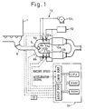
- Fig. 1 is a drawing schematically illustrating the general configuration of an embodiment of the present invention when it is applied to a diesel engine for an automobile.
- reference numeral 6 designates an exhaust gas passage of the diesel engine
- 6a and 6b designate branch exhaust gas passages diverged from the exhaust gas passage 6.
- a particulate filter (DPF) 10a and 10b which is provided with the function of a NO x absorbent is disposed on each branch passage 6a and 6b.
- the DPF 10a and 10b in this embodiment are made of, for example, a sintered metal or a metallic foam filter having numerous fine anfractuous exhaust gas paths therein.
- the DPF 10a and 10b in this embodiment are impinging trap type particulate filters.
- the NO x absorbent is attached to the wall surface of the exhaust gas paths in the DPF 10a and 10b in order to provide the function as the NO x absorbent to the DPF 10a and 10b. Therefore, in this embodiment, the upstream portions of the DPF 10a and 10b mainly act as particulate filters for trapping the particulate matter in the exhaust gas, and the downstream portions of the DPF 10a and 10b mainly act as NO x absorbent for removing NO x in the exhaust gas.
- the bodies of the DPF 10a and 10b are connected to an electric power supply (not shown) via a relay 11 in such a manner that electricity can be supplied to the DPF 10a and 10b separately.
- electricity is supplied to the DPF 10a and 10b separately during the SO x recovery operation and the regenerating operation in order to raise the temperature of the metallic bodies of the DPF 10a and 10b by the heat generated by the electric current flowing therethrough.
- the bodies of the DPF 10a and 10b act as electric heaters in this embodiment.
- numeral 9 designates a switching valve
- 9a designates an appropriate actuator for operating the switching valve 9 such as solenoid actuator or a vacuum actuator.
- a reducing agent supply unit 12 is provided for supplying reducing agent to the respective branch exhaust gas passages upstream of the DPF 10a and 10b.
- the reducing agent supply unit 12 is equipped with injection nozzles 12a and 12b which inject mists of fuel into the branch exhaust gas passages 6a and 6b upstream of the respective DPF 10a and 10b.
- the reducing agent supply unit 12 is used for lowering the oxygen concentration in the exhaust gas flowing into the DPF 10a and 10b during the NO x releasing operation and the SO x recovery operation of the DPF (NO x absorbents) 10a and 10b, as well as for the regenerating operation of the DPF 10a and 10b.
- a secondary air supply unit 13 for supplying secondary air to the respective branch exhaust gas passages 6a and 6b upstream of the DPF 10a and 10b is provided.
- the secondary air supply unit 13 includes a pressurized air source 13c such as an air pump or a pressurized air tank, and secondary air nozzles 13a and 13b disposed in the branch exhaust gas passage 6a and 6b.
- the secondary air supply unit 13 is used for supplying air for burning the particulate matter trapped in the DPF 10a and 10b during the regenerating operation of the DPF 10a and 10b.
- Numeral 30 in Fig. 1 designates an electronic control unit (ECU) of the engine.
- the ECU 30 in this embodiment comprises, for example, a microcomputer of a known type which has a CPU, a RAM, a ROM, and input and output ports all interconnected by a bi-directional bus.
- the ECU 30 performs fundamental control of the engine such as fuel injection control of the engine 1.
- the ECU 30 in this embodiment controls the NO x releasing operation and SO x recovery operation, as well as the regenerating operation, of the DPF 10a and 10b.
- various signals are fed to the input port of the ECU 30. These signals are, for example, an engine speed signal from an engine speed sensor disposed near the crankshaft (not shown) of the engine and an accelerator signal from an accelerator sensor disposed near an accelerator pedal (not shown) which represents the amount of depression of the accelerator pedal by the driver.
- the output port of the ECU 30 is connected to, for example, the fuel injection valves of the engine, the actuator 9a of the intake shutter valve 9, the reducing agent supply nozzles 12a and 12b, the secondary air nozzles 13a and 13b and the relay 11 in order to control the operations of these elements.
- the NO x absorbent in this embodiment comprises precious metals such as platinum (Pt) rhodium (Rh), and at least one substance selected from alkali metals such as potassium (K), sodium (Na), lithium (Li) and cesium (Cs); alkali-earth metals such as barium (Ba) and calcium (Ca); and rare-earth metals such as lanthanum (La) and yttrium (Y).
- the NO x absorbent absorbs NO x (nitrogen oxide) in the exhaust gas when the air-fuel ratio of the exhaust gas flowing through the DPF 10a and 10b is lean, and releases the absorbed NO x when the oxygen concentration of the exhaust gas flowing through the DPF 10a and 10b.
- the concentration of O 2 in the exhaust gas increases, i.e., when the air-fuel ratio of the exhaust gas becomes lean (i.e. when the excess air ratio ⁇ is larger than 1.0)
- the oxygen O 2 in the exhaust gas is deposited on the surface of platinum Pt in the form of O 2 - , or O 2- .
- NO in the exhaust gas reacts with O 2 - or O 2- on the surface of the platinum Pt and becomes NO 2 by the reaction 2NO + O 2 ⁇ 2NO 2 .
- NO 2 in the exhaust gas and the NO 2 produced on the platinum Pt are further oxidized on the surface of platinum Pt and absorbed into the NO x absorbent while bonding with the barium oxide BaO and diffusing in the absorbent in the form of nitric acid ions NO 3 - .
- NO x in the exhaust gas is absorbed by the NO x absorbent when the air-fuel ratio of the exhaust gas is lean.
- the NO x absorbent performs the absorbing and releasing operation of NO x in the exhaust gas in which NO x in the exhaust gas is absorbed by the NO x absorbent when the air-fuel ratio of the exhaust gas is lean and, when the air-fuel ratio of the exhaust gas becomes stoichiometric or rich, released from the NO x absorbent and reduced to N 2 .
- SO x in the exhaust gas is absorbed in the NO x absorbent when the air-fuel ratio of the exhaust gas is lean, by the same mechanism as the NO x absorbing operation.
- the absorbed SO x is held in the NO x absorbent in the form of particles of a sulfate such as BaSO 4 .
- the sulfate formed in the NO x absorbent is a stable substance.
- the sulfate held in the NO x absorbent can be also released from the NO x absorbent by the same mechanism as the NO x releasing operation when the air-fuel ratio of the exhaust gas becomes rich, it is necessary to raise the temperature of NO x absorbent to a temperature higher than the same in the NO x releasing operation, in order to release SO x from the NO x absorbent.
- SO x is not released from the NO x absorbent during the normal NO x releasing operation and tends to accumulate in the NO x absorbent.
- the amount of SO x in the NO x absorbent increases, the amount of the absorbent in the NO x absorbent which contributes to the NO x absorption decreases accordingly. Therefore, when the amount of SO x absorbed in the NO x absorbent increases, the capacity of the NO x absorbent for absorbing NO x decreases, i.e., S-deterioration occurs.
- the sulfate particles held in the NO x absorbent easily grow to larger size particles when the particles are exposed to a high temperature in a lean air-fuel ratio atmosphere.
- SO x can be released from the NO x absorbent by the SO x recovery operation in which the temperature of the NO x absorbent is raised to a temperature higher than the NO x releasing operation in a rich air-fuel ratio atmosphere, once the growth of the sulfate particles occurs, the particles are not decomposed even if they are exposed to a high temperature in a rich air-fuel ratio atmosphere. Therefore, when the growth of the sulfate particles occurs, it is difficult to recover the original NO x absorbing capacity of the NO x absorbent.
- a particulate filter When a particulate filter is disposed in the exhaust gas passage upstream of the NO x absorbent, such gas in this embodiment, usually a high temperature exhaust gas of a lean air-fuel ratio flows through the NO x absorbent during the regenerating operation of the particulate filter, and it becomes difficult to release SO x from the NO x absorbent by the SO x recovery operation due to the growth of the sulfate particles.
- the NO x releasing operation of the NO x absorbent, the SO x recovery operation of the NO x absorbent and the regenerating operation of the DPF are performed in the manner explained hereinafter in order to prevent the growth of the sulfate particles in the NO x absorbent.
- the ECU 30 switches the switching valve 9 to a position where substantially all the exhaust gas of the engine 1 is directed to one of the DPF (for example, to the DPF 10a). Since a diesel engine is used in this embodiment, the air-fuel ratio of the exhaust gas during the normal operation of the engine 1 is considerably lean. Therefore, the DPF (10a) to which the exhaust gas is directed absorbs NO x in the exhaust gas by the NO x absorbent attached to the wall surface of the exhaust gas passage in the DPF, in addition to trapping the particulate matter in the exhaust gas. When the amount of NO x absorbed in the DPF (10a) increases, the ECU 30 switches the switching valve 9 to the other position in order to direct the exhaust gas of the engine to the other DPF (10b). Thus, substantially no exhaust gas flows through the DPF (10a), and the other DPF (10b) absorbs NO x and traps particulate matter in the exhaust gas.
- the ECU 30 supplies a reducing agent to the DPF (10a) from the corresponding nozzle (12a) of the reducing agent supply unit 12.
- Substances which generate components such as hydrogen H 2 , hydrocarbon HC, and carbon monoxide CO can be used as the reducing agent. Therefore, reducing gases such as hydrogen gas or carbon monoxide gas, gaseous or liquid hydrocarbons such as propane, propylene or butane, and liquid fuels such as gasoline, diesel fuel or kerosene, etc., can be used as the reducing agent in the present invention.
- fuel of the engine 1, i.e., diesel fuel is used as reducing agent in order to facilitate the storage and replenishment thereof.
- the reducing agent When the reducing agent is supplied to the DPF, the reducing agent is oxidized on the surface of the platinum Pt in the NO x absorbent. This makes the air-fuel ratio of the exhaust gas rich, i.e., the oxygen concentration in the exhaust gas becomes low and HC and CO are generated by the oxidation of the reducing agent. Therefore, NO x absorbed in the NO x absorbent is released and reduced by HC and CO as explained before, i.e., the NO x releasing operation is performed.
- the ECU 30 performs the SO x recovery operation instead of the NO x releasing operation if the amount of SO x absorbed in the NO x absorbent becomes large.
- the SO x recovery operation similarly to the NO x releasing operation, the reducing agent is supplied to the DPF while stopping the exhaust gas flow.
- the temperature of the DPF is further raised by closing the contacts of the relay 11. When the relay is closed, electricity is supplied to the body of the DPF and the whole body of the DPF is heated by electric current.
- the temperature of the DPF rises to a temperature required for the SO x recovery operation (for example, about 500°C) in a short time.
- a temperature required for the SO x recovery operation for example, about 500°C
- the ECU 30 performs the regenerating operation of the DPF immediately after the completion of the SO x recovery operation. Namely, after releasing all the SO x absorbed in the NO x absorbent, the ECU 30 supplies secondary air to the DPF from the secondary air supply unit 13. Since the temperature of the DPF is high immediately after the SO x recovery operation, the particulate matter trapped in the DPF burns when air (oxygen) is supplied to the DPF. In this condition, the amount of secondary air must be sufficient to supply oxygen for burning particulate matter in the DPF. In this condition, the NO x absorbent in the DPF is exposed to a high temperature in a lean air-fuel ratio atmosphere.
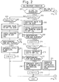
- Figs. 2 and 3 are a flowchart explaining the SO x recovery operation as explained above. This operation is performed by a routine executed by the ECU 30 at predetermined intervals.
- the ECU 30 determines which DPF is operating (i.e., to which DPF the exhaust gas is directed) from the position of the switching valve 9. If the DPF 10a, for example, is operating at step 201, the ECU 30 further determines whether the amount of SO x absorbed in the DPF 10a has increased to a predetermined value based on the value of a SO x counter CSA at step 203.
- CSA is a counter representing the amount of SO x absorbed in the DPF 10a and the value thereof is set by the operation in Fig. 4 which will be explained later.
- the ECU 30 switches the switching valve 9 to the position where all the exhaust gas is directed to the other DPF 10b at step 205.
- the ECU 30 further supplies electricity to the DPF 10a to raise the temperature of the DPF 10a to above a predetermined temperature (about 500°C and preferably 600°C) and supplies reducing agent to the DPF 10a from the reducing agent supply unit 12.
- the DPF 10a is isolated from the exhaust gas flow and exposed to a high temperature in a lean air-fuel ratio atmosphere and, thereby, the absorbed SO x is released from the DPF 10a.
- This SO x recovery operation is continued for a predetermined period at step 209.
- the period for continuing the SO x recovery operation is a period sufficient for releasing the amount of the absorbed SO x (i.e., the amount corresponding to the value CS 0 of the SO x counter) and determined by experiment.
- the ECU 30 clears the value of the SO x counter CSA at step 211.
- the ECU 30 After clearing the value of the SO x counter, the ECU 30 further determines whether the regenerating operation of the DPF 10a is required at step 213. Namely, at step 213, the ECU 30 determines whether the amount of the particulate matter trapped in the DPF 10a has reached a predetermined value by comparing the value of a particulate counter CPA with a predetermined value CP 0 .
- Particulate counter CPA is a counter representing the amount of particulate matter trapped in the DPF 10a, and the value thereof is set by the operation in Fig. 4.
- the ECU 30 supplies secondary air to the DPF 10a from the nozzle 13a of the secondary air supply unit 13 at step 215.
- the amount of secondary air and the amount of the reducing agent supplied to the DPF 10a is set in such a manner that the temperature of the DPF 10a does not become excessively high (for example, less than 800°C).
- this regenerating operation of the DPF 10 is continued for a predetermined period.
- the period for continuing the regenerating operation is a period sufficient for burning the amount of the trapped particulate matter (i.e., the amount corresponding to the value CP 0 of the particulate counter) and determined by experiment.
- the ECU 30 stops the supply of the reducing agent and secondary air as well as the supply of the electricity to the DPF 10a at step 218, and clears the value of the particulate counter CSA at step 219.
- the regenerating operation of the DPF 10a is completed.
- the DPF 10a is kept in this condition and isolated from the exhaust gas until the switching valve 9 is switched to the position where the exhaust gas is directed to the DPF 10a. If CPA ⁇ CP 0 at step 213, since this means that the regenerating operation of the DPF 10a is not necessary, the ECU 30 immediately stops the supply of the reducing agent and electricity to the DPF 10a.
- step 223 determines whether the NO x releasing operation of the DPF 10a is required.
- step 223 it is determined whether the value of a NO x counter CNA has increased to a predetermined value CN 0 .
- the NO x counter CNA represents the amount of NO x absorbed in the DPF 10a, and is set by the operation in Fig. 4.
- the ECU 30 isolates the DPF 10a from the exhaust gas by switching the switching valve 9 to the position where the exhaust gas is directed to the DPF 10b at step 225, and supplies the reducing agent to the DPF 10a from the nozzle 12a of the reducing agent supply unit 12 at step 227.
- the DPF 10a is exposed to a relatively low temperature and a rich air-fuel ratio atmosphere to perform the NO x releasing operation.
- the NO x releasing operation is continued for a predetermined period.
- the period for continuing the NO x releasing operation is a period required for releasing the amount of NO x absorbed in the DPF 10a (the amount corresponding to the value CN 0 of the counter CNA), and determined by experiment.
- the ECU 30 stops the supply of the reducing agent at step 230, and clears the value of the NO x counter CNA of the DPF 10a at step 231.
- the DPF 10a is reserved in this condition until the switching valve 9a is switched to the position where the exhaust gas is directed to the DPF 10a.
- step 201 If the DPF 10b is operating at step 201, the operations exactly the same as those explained above are performed for DPF 10b at steps 233 through 261 in Fig. 3. Since steps 233 through 261 in Fig. 3 are the same as steps 203 through 231 in Fig. 2, the detailed explanation is omitted.
- CSB, CPB and CNB in steps 233, 243 and 253 are the SO x counter, the particulate counter and the NO x counter of the DPF 10b.
- Fig. 4 is a flowchart explaining the setting operation of the SO x counters (CSA, CSB), the particulate counters (CPA, CPB) and the NO x counters (CNA, CNB) used in the operation in Figs. 2 and 3.
- This operation is performed by a routine executed by the ECU 30 at predetermined intervals. In this operation, the ECU 30 increases the values of the respective counters by the amounts determined by the operating condition of the engine.
- the values of the SO x counters, the particulate counters and the NO x counters represent the amounts of SO x , particulate and NO x absorbed or trapped in the respective DPF.
- the amount of SO x absorbed in the DPF is considered. It is considered that the amount of SO x absorbed by the DPF per unit time is proportional to the amount of SO x produced by the engine per unit time. Since the amount of SO x produced by the engine per unit time is determined by the engine load (i.e., the amount of fuel burned in the engine per unit time), the amount of SO x absorbed by the DPF per unit time is determined by the engine load. In this embodiment, the amounts of SO x absorbed by the DPF per unit time (the time corresponding to the interval for performing the operation in Fig.
- the ECU 30 calculates the amount of SO x absorbed by the DPF during the period since the operation was last performed based on the value of the accelerator signal and the engine speed using this numerical map, and increases the value of the SO x counter by the calculated amount.
- the value of the SO x counter represents the accumulated amount of SO x absorbed in the DPF, i.e. the amount of SO x held in the DPF.
- the amount of NO x absorbed in the DPF per unit time and the amount of particulate trapped by the DPF per unit time are determined by the engine load condition.
- the amount of NO x and the particulate absorbed or trapped in the DPF per unit time, at the various engine loads, are previously obtained, by experiment, and stored in the ROM of the ECU 30 as numerical tables similar to that of SO x .
- the ECU 30 also calculates the amounts of NO x and particulate absorbed or trapped by the DPF during the period since the operation was last performed, and increases the value of the NO x counter and the particulate counter by the calculated amounts.
- the values of the NO x counter and the particulate counter represent the amount of NO x and particulate, respectively, held in the DPF.
- ⁇ CS represents the amount of particulate trapped by the DPF since the operation was last performed
- ⁇ CS and ⁇ CN represent the amounts of SO x and NO x absorbed by the DPF, respectively, since the operation was last performed.
- the ECU 30 determines which of the DPFs is now operating and, if the DPF 10a is operating, increases the SO x counter CSA, the particulate counter CPA and the NO x counter CNA of the DPF 10a at steps 407 through 411 by the amounts ⁇ CS, ⁇ CP and ⁇ CN, respectively. If the DPF 10b is operating at step 405, the counters CSB, CPB and CNB are increased by the amounts ⁇ CS, ⁇ CP and ⁇ CN at steps 413 through 417, respectively. Therefore, by the operation in Fig. 4, the counters of the DPF 10a and 10b represent the amounts of SO x particulate and NO x absorbed or trapped in the respective DPF. As explained in Figs.
- the values of the SO x counters, the particulate counters and the NO x counters of the DPF 10a and 10b are cleared when the SO x recovery operation, the regenerating operation and the NO x releasing operation of the respective DPF is completed.
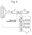
- Fig. 5 illustrates the general configuration of another embodiment of the present invention.
- reference numerals same as those in Fig. 1 designate the elements same as in Fig. 1.
- a diesel engine for an automobile is also used for the engine 1 in this embodiment.
- branch exhaust gas passages 6a and 6b are not provided to the exhaust gas passage 6 of the engine 1, and a three-way catalyst (or an oxidizing catalyst) 51 and a NO x absorbent 53 are disposed in the exhaust gas passage 6 in this order from the upstream side.
- an exhaust gas temperature sensor 55 is disposed in the exhaust gas passage 6 at the inlet of the NO x absorbent 53, and supply a voltage signal corresponding to the temperature of the exhaust gas flowing into the NO x absorbent 53.
- the reducing agent supply unit 12 and nozzles 12a and 12b are not provided.
- the three-way catalyst 51 in this embodiment uses a honeycomb substrate made of a material such as cordierite, and a thin coat of alumina is applied on the surface of the substrate. Catalytic components of precious metals, such as platinum (Pt), Palladium (Pd) or rhodium (Rh) are attached to the alumina coat.
- the three-way catalyst 51 oxidizes SOF (soluble organic fractions), as well as HC and CO in the exhaust gas when the air-fuel ratio of the exhaust gas is lean.
- SOF soluble organic fractions
- HC HC
- CO oxidizing ability for SOF and HC, CO can be obtained.
- the NO x absorbent 53 in this embodiment uses, for example, a honeycomb type substrate made of cordierite. On this substrate, an alumina layer which acts as a carrier of the catalytic components is applied. On this carrier, precious metals such as platinum (Pt) rhodium (Rh), and at least one substance selected from alkali metals such as potassium (K), sodium (Na), lithium (Li) and cesium (Cs); alkali-earth metals such as barium (Ba) and calcium (Ca); and rare-earth metals such as lanthanum (La) and yttrium (Y) is carried.
- the NO x absorbent 53 performs absorbing and releasing operation of NO x the same as that of the NO x absorbent in the embodiment in Fig. 1.
- the three-way catalyst 51 tends to suffer SOF-deterioration during the operation of the engine. Therefore, in order to resume the catalytic ability, the SOF recovery operation, in which the SOF attached to the surface of the catalyst is burned at a high temperature in a lean air-fuel ratio atmosphere, must be performed periodically.
- the NO x absorbent 53 is disposed in the exhaust gas passage 6 downstream of the three-way catalyst 51, the growth of the sulfate particles may occur when a lean air-fuel ratio exhaust gas at a high temperature flows through the NO x absorbent 53 during the SOF recovery operation of the three-way catalyst 51.
- the SO x recovery operation of the NO x absorbent 53 is performed always before the SOF recovery operation in order to release SO x in the NO x absorbent 53 before a lean air-fuel ratio exhaust gas at a high temperature flows into the NO x absorbent 53.
- the exhaust gas temperature of the diesel engine 1 is generally low, the exhaust gas temperature sometimes becomes high depending on the engine operating condition (the engine load). Therefore, in some cases, a high temperature and lean air-fuel ratio exhaust gas may flow through the NO x absorbent 53 depending on the operating condition of the engine 1 even if the SOF recovery operation is not performed. In this case, the growth of the sulfate particles in the NO x absorbent 53 occurs irrespective of the SOF recovery operation of the three-way catalyst 51.
- the SO x recovery operation is performed in accordance with the exhaust gas temperature in addition to the SO x recovery operations similar to that in the previous embodiment.
- the ECU 30 monitors the amount of SO x absorbed in the NO x absorbent, and performs the SO x recovery operation when the amount of the absorbed SO x reaches a predetermined amount. Further, the ECU 30 monitors the exhaust gas temperature TE, and performs the SO x recovery operation when the temperature TE reaches a predetermined temperature TE 0 even though the amount of SO x absorbed in the NO x absorbent 53 is lower than the predetermined amount.
- the temperature TE 0 is set at a temperature lower than a growth temperature at which the growth of the sulfate particles due to sintering occurs.
- the SO x recovery operation is performed by injecting fuel into the cylinders of the engine 1 during the expansion stroke or the exhaust stroke of the respective cylinders in addition to the normal fuel injection during the compression stroke.
- the injected fuel vaporizes in the cylinder without burning and is discharged from the cylinder with the exhaust gas. Therefore, when the additional fuel injection is performed during the expansion or exhaust stroke, the amount of HC (unburned fuel) largely increases. Further, since the fuel injected during the expansion or exhaust stroke does not burn in the cylinder, the maximum cylinder pressure and the output torque of the cylinder do not increase.
- the expansion stroke fuel injection the fuel injection during the expansion or exhaust strokes of the cylinders (hereinafter referred to as "the expansion stroke fuel injection"), it is possible to supply a rich air-fuel ratio exhaust gas to the NO x absorbent 53.
- the exhaust gas containing a relatively large amount of unburned fuel flows through the three-way catalyst 51 disposed upstream, and the unburned fuel in the exhaust gas is oxidized at the three-way catalyst 51.
- the oxygen concentration in the exhaust gas is lowered and, at the same time, the temperature of the exhaust gas rises. Therefore, a high temperature and a rich air-fuel ratio exhaust gas flows into the NO x absorbent 53 downstream of the three-way catalyst 51, and the SO x recovery operation of the NO x absorbent 53 is performed by this high temperature and rich air-fuel ratio exhaust gas.
- the SO x recovery operation of the NO x absorbent 53 is continued for a period required for releasing all SO x absorbed in the NO x absorbent 53 and, when all SO x in the NO x absorbent 53 is released, the amount of the expansion stroke fuel injection is decreased to the amount which makes the air-fuel ratio of the exhaust gas lean.
- the air-fuel ratio of the exhaust gas flowing through the three-way catalyst becomes lean, since a sufficient amount of oxygen is supplied to the three-way catalyst 51, the temperature of the three-way catalyst 51 increases due to the oxidation of the unburned fuel in the exhaust gas. Due to this high temperature and lean air-fuel ratio atmosphere, the SOF attached to the surface of the catalyst burns, and the SOF recovery operation of the three-way catalyst is performed.
- Figs. 6 and 7 are a flowchart explaining the SO x recovery operation of this embodiment. This operation is performed by a routine executed by the ECU 30 at predetermined timings.
- the ECU 30 reads the exhaust gas temperature TE at the inlet of the NO x absorbent 53 from the exhaust gas temperature sensor 55 and compares it with a predetermined temperature TE 0 . If TE ⁇ TE 0 at step 603, the ECU 30 determines whether the value of the SO x counter CS has reached a predetermined value CS 0 , i.e., whether the amount of SO x absorbed in the NO x absorbent 53 is larger than a predetermined value.
- the SO x counter CS is a counter similar to CSA, CSB in Figs. 2 and 3 and represents the amounts of SO x absorbed in the NO x absorbent 53.
- the value of the SO x counter is set by the operation in Fig. 8. If CS ⁇ CS 0 at step 603, i.e., if the amount of SO x absorbed in the NO x absorbent 53 is larger than the predetermined amount, the ECU 30 immediately performs an SO x recovery operation at steps 605 through 609. Namely, the expansion stroke fuel injection of the engine 1 is performed at step 605 to supply exhaust gas containing a large amount of unburned fuel to the three-way catalyst 51 upstream of the NO x absorbent 53.
- the temperature of the exhaust gas flowing through the three-way catalyst 51 becomes high due to the oxidation of fuel on she three-way catalyst, and a high temperature and rich air-fuel ratio exhaust gas flows into the NO x absorbent 53 downstream of the three-way catalyst 51.
- the absorbed SO x is released from the NO x absorbent 53.
- This SO x recovery operation is continued until a predetermined time elapses at step 607.
- the predetermined time at step 607 is a time sufficient for releasing all the absorbed SO x (the amount corresponding to CS 0 ) from the NO x absorbent 51, and is determined by experiment.
- the amount of the expansion stroke fuel injection is determined in such a manner that the air-fuel ratio of the exhaust gas flowing through the NO x absorbent 53 becomes a rich air-fuel ratio sufficient to release SO x from the NO x absorbent 53.
- the value of the SO x counter CS is cleared at step 609.
- an electric heater may be provided on the NO x absorbent 53. If the electric heater is provided, the heater is activated at step 605 to further raise the temperature of the NO x absorbent 53 in order to complete the SO x recovery operation in a short time.
- Steps 611 through 617 represent the SOF recovery operation of the three-way catalyst 51.
- the SOF recovery operation is performed after the completion of the SO x recovery operation of the NO x absorbent 53, also in this embodiment.
- the ECU 30 determines whether the value of the SOF counter CF has reached a predetermined value CF 0 .
- the SOF counter CF is a counter representing the amount of SOF attached to the three-way catalyst 51, and is set by the operation in Fig. 8.
- CF ⁇ CF 0 at step 611 i.e., if the amount of SO x attached to the three-way catalyst 51 is larger than a predetermined amount, the amount of the expansion stroke fuel injection is reduced to an amount which makes the air-fuel ratio of the exhaust gas flowing into the three-way catalyst lean.
- the amount of the expansion fuel injection is reduced, although the temperature of the three-way catalyst 51 is maintained at a high temperature due to the oxidation of the unburned fuel, the air-fuel ratio of the exhaust gas flowing through the three-way catalyst becomes lean.
- the three-way catalyst 51 is exposed to a lean air-fuel ratio atmosphere at a high temperature, and the SOF attached to the three-way catalyst burns.
- the high temperature lean air-fuel ratio exhaust gas from the three-way catalyst 51 flows into the NO x absorbent 53.
- SO x absorbed in the NO x absorbent 53 was already released by the SO x recovery operation at steps 605 through 609, the growth of the sulfate particles does not occur.
- the SOF recovery operation is performed by the expansion stroke fuel injection until the predetermined time elapses at step 615.
- the predetermined time at step 615 is a time sufficient for burning all the amount of SOF attached to the three-way catalyst 51 (the amount corresponding to CF 0 ), and determined by experiment.
- the expansion stroke fuel injection is terminated at step 619, i.e., the SOF recovery operation is not performed in this case.
- the ECU 30 executes step 621 in Fig. 7 to determine whether the NO x releasing operation of the NO x absorbent 53 is required. Namely, at step 621, the ECU 30 determines whether the value of the NO x counter CN has reached to a predetermined value CN 0 . If CN ⁇ CN 0 , since this means that the amount of NO x absorbed in the NO x absorbent 53 is large, the ECU 30 performs the NO x releasing operation at steps 623 through 627. At step 623, the expansion stroke fuel injection is performed to supply a rich air-fuel ratio exhaust gas to the NO x absorbent 53.
- the amount of the expansion stroke fuel injection during the NO x releasing operation is smaller than that during the SO x recovery operation, and is set at an amount sufficient for maintaining the air-fuel ratio of the exhaust gas flowing into the NO x absorbent 51 rich.
- the expansion stroke fuel injection is continued until a predetermined time elapses at step 625.
- the predetermined time in step 625 is a time sufficient for releasing the amount of NO x corresponding to CN 0 from the NO x absorbent 53, and determined by experiment.
- the expansion stroke fuel injection is terminated at step 626, and the value of the NO x counter CN is cleared at step 627.
- the NO x releasing operation of the NO x absorbent 53 is completed.
- Steps 629 through 633 represent the SO x recovery operation performed for preventing the growth of the sulfate particles when the exhaust gas temperature rises due to the operating condition of the engine. Since the temperature TE 0 is a temperature slightly lower than the growth temperature where the sulfate particles in the NO x absorbent grow in a lean air-fuel ratio atmosphere, if the exhaust gas temperature TE at the inlet of the NO x absorbent increases to TE 0 at step 601, the exhaust gas temperature may further increases to the growth temperature. Therefore, in this case, it is necessary to release all SO x absorbed in the NO x absorbent 53 before the exhaust gas temperature reaches the growth temperature, in order to prevent the growth of the sulfate particles.
- the ECU 30 executes step 629 in Fig. 6 to perform the SO x recovery operation and carries out the expansion stroke fuel injection irrespective of the amount of SO x absorbed in the NO x absorbent 53.
- the ECU 30 determines the time T required for releasing all the amount of SO x from the NO x absorbent 53 based on the value of the NO x counter CS. The time T required for continuing the SO x recovery operation varies in accordance with the amount of SO x absorbed in the NO x absorbent.
- the relationship between the amount of SO x absorbed in the NO x absorbent and the time T required for releasing all SO x absorbed in the NO x absorbent is previously obtained by experiment, and the required time T is stored in the ROM of ECU 30 as a function of the value of NO x counter CS.
- the time T required for continuing the SO x recovery operation is determined from the value of the SO x counter CS based on the relationship stored in the ROM.
- the SO x recovery operation is continued until the time T determined at step 631 elapses.
- the value of the SO x counter CS is cleared, and the ECU 30 executes step 611 in Fig. 7 and performs, if necessary, the SOF recovery operation of the three-way catalyst 51.
- a reducing agent supply unit similar to that in Fig. 1 may be provided to supply reducing agent to the exhaust gas passage upstream of the three-way catalyst 51.
- reducing agent diesel fuel
- steps 605, 613, 623 and 629 instead of performing the expansion stroke fuel injection.
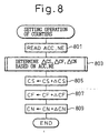
- Fig. 8 shows a flowchart explaining the setting operation of the counters CS, CF and CN used in the operation in Figs. 6 and 7.
- the values of the counters CS and CN are set by the manner same as that in Fig. 4. Namely, the amounts of SO x and NO x absorbed in the NO x absorbent ( ⁇ CS and ⁇ CN) per unit time are determined from the engine load (ACC) and the engine speed (NE) based on the numerical tables stored in the ROM (step 803) and the value of the counters CS and CN are set at the accumulated values of ⁇ CS and ⁇ CN, respectively (steps 805 and 809).
- the amount of SOF attached to the three-way catalyst per unit time ⁇ CF is obtained previously at various engine load and speeds, by experiment, and stored in the ROM of the ECU 30 as a form of a numerical table similar to those for SO x and NO x .
- the amount of SOF attached to the three-way catalyst per unit time ⁇ CF is determined from the engine load (ACC) and the engine speed (NE) (step 803) and the value of the SOF counter CF is set at the accumulated value of ⁇ CF (step 807).
- FIGs. 9 and 10 illustrate general configurations of other embodiments of the present invention.
- reference numerals same as those in Figs. 1 and 5 designate the same elements.
- Fig. 9 shows the case where the three-way catalyst 51 in Fig. 5 is replaced by a DPF 91.
- the DPF 91 has a construction similar to that of the DPF 10a and 10b in Fig. 1, except that NO x absorbent is not attached to the wall surfaces of the exhaust gas paths in the DPF 91.
- the reducing agent supply unit 12 are the nozzle 12a are provided for supplying reducing agent to the exhaust gas passage 6 upstream of the DPF 91.
- the DPF 91 and the NO x absorbent 53 in this embodiment use metal substrates similar to those in Fig. 1, which act as electric heaters. Therefore, the DPF 91 and the NO x absorbent 53 can be heated during the regenerating operation of the DPF 91 and the SO x recovery operation of the NO x absorbent 53 when the exhaust gas temperature is low.
- the ECU 30 monitors the amount of SO x absorbed in the NO x absorbent 53 by the SO x counter similar to the previous embodiments and, when the amount of SO x increases, the ECU 30 performs the SO x recovery operation by supplying reducing agent from the unit 12 to the exhaust gas and by heating the NO x absorbent 53 by supplying electricity to the substrate thereof. Further, the ECU monitors the amount of particulate trapped in the DPF 91 by the particulate counter similar to the previous embodiments and, if the amount of particulate increases, performs the regenerating operation after completing the SO x recovery operation of the NO x absorbent as explained above. The SO x recovery operation is also performed in the manner similar to that in the embodiment of Figs. 6 and 7 when the exhaust gas temperature increases to the predetermined temperature TE 0 to prevent the growth of the sulfate particles in the NO x absorbent 53.
- Fig. 10 shows the case where the DPF 91 and the NO x absorbent 53 in Fig. 9 are combined.
- the DPF 1001 in this embodiment carries the NO x absorbent and acts as both the particulate filter and the NO x absorbent.
- the respective recovery operations are performed by the expansion stroke fuel injection, and the reducing agent supply unit 12 in Fig. 9 is not provided.
- the SO x recovery operation, the NO x releasing operation and the regenerating operation of DPF 1001 is the same as the operation in the embodiment of Fig. 9, and a detailed explanation is omitted.
- this invention also can be applied to an other type of internal combustion engine, such as a gasoline engine, which can be operated at a lean air-fuel ratio.
- an exhaust gas passage of a diesel engine diverges into two branch pipes and a particulate filter (DPF) is disposed in each of the branch pipes.
- the DPF uses a metallic substrate and NO x absorbent is attached to the wall of the paths in the DPF. Therefore, the DPF act as both a normal particulate filter and a NO x absorbent.
- SO x SO x
- NO x NO x absorbent
- An electronic control unit monitors the amount of SO x absorbed in the DPF during the operation and, when the amount of SO x absorbed in one DPF increases, switches the exhaust gas flow to the other DPF.
- the ECU further performs the SO x recovery operation to release the absorbed SO x from the DPF.
- the ECU After completing the SO x recovery operation, the ECU performs the regenerating operation of the DPF in which the particulate matter trapped in the DPF is burned. Since SO x in DPF is already released by the previous SO x recovery operation when the regenerating operation of the DPF is performed, the growth of sulfate particle in the DPF does not occur even if the DPF is exposed to a high temperature lean air-fuel ratio atmosphere of the regenerating operation.
Abstract
Description
Claims (6)
- An exhaust gas purification device for an engine comprising:a NOx absorbent disposed in an exhaust gas passage of an internal combustion engine, wherein said NOx absorbent absorbs NOx in the exhaust gas of the engine when the air-fuel ratio of the exhaust gas is at a lean air-fuel ratio and releases the absorbed NOx when the oxygen concentration in the exhaust gas is lowered, and wherein said NOx absorbent absorbs SOx in the exhaust gas when the air-fuel ratio of the exhaust gas is at a lean air-fuel ratio and releases the absorbed SOx when the oxygen concentration in the exhaust gas is lowered and when the temperature of the NOx absorbent is higher than a SOx releasing temperature;SOx releasing means for raising the temperature of the NOx absorbent to a temperature higher than the SOx releasing temperature and for lowering the oxygen concentration of the exhaust gas flowing into the NOx absorbent to, thereby, release the absorbed SOx from the NOx absorbent; andSOx control means for controlling the amount of SOx absorbed in the NOx absorbent by controlling the SOx releasing means in such a manner that, when it is expected that the temperature of the NOx absorbent increases to a first predetermined temperature when the air-fuel ratio of the exhaust gas is lean, substantially all of the absorbed SOx is released from the NOx absorbent by the SOx releasing means before the temperature of the NOx absorbent reaches said first predetermined temp.
- An exhaust gas purification device as set forth in claim 1 wherein said NOx absorbent holds the absorbed SOx therein in the form of a particle of sulfate, and wherein said first predetermined temperature is a temperature at which the sulfate particles in the NOx absorbent starts to grow in a lean air-fuel ratio exhaust gas.
- An exhaust gas purification device as set forth in claim 1, wherein said SOx control means further comprises an exhaust gas temperature detecting means for detecting the temperature of the exhaust gas flowing into the NOx absorbent and activates the SOx releasing means when the temperature of the exhaust gas increases to a second predetermined temperature which is lower than the first predetermined temperature.
- An exhaust gas purification device as set forth in claim 1, further comprising:purifying means disposed in the exhaust gas passage upstream of the NOx absorbent for removing a specific component contained in the exhaust gas; andburning means for burning the specific component trapped by or attached to the purifying means by raising the temperature of the purifying means and by supplying a lean air-fuel ratio exhaust gas to the purifying means,
wherein said SOx controlling means activates the SOx releasing means before activating the burning means. - An exhaust gas purification device as set forth in claim 4, wherein said specific component is a soluble organic fraction, and said purifying means is an oxidizing catalyst or three-way catalyst which oxidizes the soluble organic fraction in the exhaust gas.
- An exhaust gas purification device as set forth in claim 4, wherein said specific component is particulate matter in the exhaust gas, and said purifying means is a particulate filter which traps the particulate matter in the exhaust gas.
Applications Claiming Priority (6)
| Application Number | Priority Date | Filing Date | Title |
|---|---|---|---|
| JP4893297 | 1997-03-04 | ||
| JP48932/97 | 1997-03-04 | ||
| JP4893297 | 1997-03-04 | ||
| JP03506898A JP3645704B2 (en) | 1997-03-04 | 1998-02-17 | Exhaust gas purification device for internal combustion engine |
| JP35068/98 | 1998-02-17 | ||
| JP3506898 | 1998-02-17 |
Publications (3)
| Publication Number | Publication Date |
|---|---|
| EP0862941A2 true EP0862941A2 (en) | 1998-09-09 |
| EP0862941A3 EP0862941A3 (en) | 1998-12-16 |
| EP0862941B1 EP0862941B1 (en) | 2002-08-28 |
Family
ID=26373979
Family Applications (1)
| Application Number | Title | Priority Date | Filing Date |
|---|---|---|---|
| EP98103727A Revoked EP0862941B1 (en) | 1997-03-04 | 1998-03-03 | An exhaust gas purification device for an internal combustion engine |
Country Status (4)
| Country | Link |
|---|---|
| US (1) | US5974791A (en) |
| EP (1) | EP0862941B1 (en) |
| JP (1) | JP3645704B2 (en) |
| DE (1) | DE69807370D1 (en) |
Cited By (38)
| Publication number | Priority date | Publication date | Assignee | Title |
|---|---|---|---|---|
| WO2000021647A1 (en) * | 1998-10-12 | 2000-04-20 | Johnson Matthey Public Limited Company | Process and apparatus for treating combustion exhaust gas |
| WO2000023702A1 (en) * | 1998-10-16 | 2000-04-27 | Volkswagen Aktiengesellschaft | METHOD AND DEVICE FOR DESULFURIZING A NOx ACCUMULATING CATALYST SYSTEM |
| WO2000028196A1 (en) * | 1998-11-06 | 2000-05-18 | Ceryx Incorporated | Integrated apparatus for removing pollutants from a fluid stream in a lean-burn environment with heat recovery |
| EP1072764A1 (en) * | 1999-07-28 | 2001-01-31 | Renault | System and method of treating exhaust gases of a combustion engine |
| EP1072763A1 (en) * | 1999-07-28 | 2001-01-31 | Renault | System and method of treating particles and nitrogen oxydes for an internal combustion engine |
| FR2796984A1 (en) * | 1999-07-28 | 2001-02-02 | Renault | In-line exhaust gas treatment system for diesel or lean burn petrol engines has trap absorbing and releasing nitrogen oxides under specified conditions |
| WO2001051779A1 (en) * | 2000-01-15 | 2001-07-19 | Volkswagen Aktiengesellschaft | METHOD AND DEVICE FOR CONTROL OF DESULPHURISATION OF AN NOx STORAGE CATALYST ARRANGED IN AN EXHAUST SYSTEM OF AN INTERNAL COMBUSTION ENGINE |
| EP1223312A1 (en) * | 2001-01-12 | 2002-07-17 | Renault | Exhaust gas after-treatment system for a combustion engine and method of controling such a system |
| WO2002090732A1 (en) * | 2001-05-10 | 2002-11-14 | Robert Bosch Gmbh | Method for operating an internal combustion engine, especially a motor vehicle internal combustion engine |
| FR2827796A1 (en) * | 2001-07-25 | 2003-01-31 | Inst Francais Du Petrole | MATERIAL FOR THE REMOVAL OF NITROGEN OXIDES WITH SHEET STRUCTURE |
| EP1041263A3 (en) * | 1999-03-30 | 2003-04-02 | Nissan Motor Co., Ltd. | Catalyst temperature control device and method of internal combustion engine |
| EP1174600A3 (en) * | 2000-07-21 | 2003-06-18 | Toyota Jidosha Kabushiki Kaisha | Emission control system and method of internal combustion engine |
| EP1108876A3 (en) * | 1999-12-16 | 2003-09-24 | Toyota Jidosha Kabushiki Kaisha | Internal combustion engine |
| EP1186764A3 (en) * | 2000-09-07 | 2003-11-12 | Nissan Motor Co., Ltd. | Engine exhaust gas purification device |
| EP1243766A3 (en) * | 2001-03-21 | 2003-11-12 | Nissan Motor Co., Ltd. | Exhaust gas purification device of internal combustion engine |
| EP1148227A3 (en) * | 2000-04-18 | 2003-11-26 | Toyota Jidosha Kabushiki Kaisha | Exhaust gas purification device |
| EP1300554A3 (en) * | 2001-10-04 | 2004-01-02 | Toyota Jidosha Kabushiki Kaisha | Exhaust gas purification device of internal combustion engine |
| FR2842247A1 (en) * | 2002-07-12 | 2004-01-16 | Toyota Motor Co Ltd | SYSTEM FOR CONTROLLING THE EXHAUST EMISSIONS OF AN INTERNAL COMBUSTION ENGINE |
| EP1229231A3 (en) * | 2001-02-06 | 2004-05-06 | Toyota Jidosha Kabushiki Kaisha | Direct injection type engine |
| EP1428567A1 (en) * | 2002-12-10 | 2004-06-16 | Toyota Jidosha Kabushiki Kaisha | Exhaust emission control apparatus for internal combustion engine |
| EP1510679A2 (en) * | 2003-08-29 | 2005-03-02 | Toyota Jidosha Kabushiki Kaisha | Excessive sulfur poisoning recovery control method and apparatus for exhaust gas control catalyst |
| EP1533490A1 (en) * | 2003-11-24 | 2005-05-25 | Institut Français du Pétrole | Mehod and apparatus for the desulphurisation of a NOx storage catalyst and the regeneration of a particulate filter |
| EP1583890A2 (en) * | 2002-12-04 | 2005-10-12 | HydrogenSource LLC | Continuous flow, nox-reduction adsorption unit for internal combustion engines |
| EP1600612A1 (en) * | 2000-05-12 | 2005-11-30 | Umicore AG & Co. KG | Process for separating nitrogen oxides and soot particles from a lean exhaust gas from a combustion engine and exhaust gas cleaning system therefor |
| EP1612382A2 (en) * | 1998-11-06 | 2006-01-04 | Ceryx Asset Recovery, LLC | Integrated apparatus for removing pollutants from a fluid stream in a lean-burn environment with heat recovery |
| EP1703106A1 (en) | 2005-02-04 | 2006-09-20 | International Truck Intellectual Property Company, LLC. | System and method for diesel particulate trap regeneration in a motor vehicle with an auxiliary power unit |
| EP1176290B1 (en) * | 2000-07-24 | 2007-02-28 | Toyota Jidosha Kabushiki Kaisha | Exhaust gas purification device for internal combustion engine |
| EP1789863A2 (en) * | 2004-09-13 | 2007-05-30 | International Engine Intellectual Property Company, LLC. | Transient compensation of egr and boost in an engine using accelerator pedal rate data |
| EP1882087A2 (en) * | 2005-05-19 | 2008-01-30 | General Motors Global Technology Operations, Inc. | Exhaust aftertreatment system and method of use for lean burn internal combustion engines |
| WO2008079808A1 (en) * | 2006-12-22 | 2008-07-03 | Alstom Technology Ltd | A method and apparatus for catalyst regeneration |
| US8499548B2 (en) | 2008-12-17 | 2013-08-06 | Donaldson Company, Inc. | Flow device for an exhaust system |
| US8539761B2 (en) | 2010-01-12 | 2013-09-24 | Donaldson Company, Inc. | Flow device for exhaust treatment system |
| US8915064B2 (en) | 2007-05-15 | 2014-12-23 | Donaldson Company, Inc. | Exhaust gas flow device |
| US8938954B2 (en) | 2012-04-19 | 2015-01-27 | Donaldson Company, Inc. | Integrated exhaust treatment device having compact configuration |
| US9670811B2 (en) | 2010-06-22 | 2017-06-06 | Donaldson Company, Inc. | Dosing and mixing arrangement for use in exhaust aftertreatment |
| US9707525B2 (en) | 2013-02-15 | 2017-07-18 | Donaldson Company, Inc. | Dosing and mixing arrangement for use in exhaust aftertreatment |
| CN114961926A (en) * | 2022-05-31 | 2022-08-30 | 潍柴动力股份有限公司 | Post-processing system and control method for post-processing system |
| CN114961926B (en) * | 2022-05-31 | 2024-04-16 | 潍柴动力股份有限公司 | Aftertreatment system and control method for aftertreatment system |
Families Citing this family (217)
| Publication number | Priority date | Publication date | Assignee | Title |
|---|---|---|---|---|
| DE19747670C1 (en) * | 1997-10-29 | 1998-12-10 | Daimler Benz Ag | Exhaust gas cleaning system for internal combustion engine |
| US6237330B1 (en) * | 1998-04-15 | 2001-05-29 | Nissan Motor Co., Ltd. | Exhaust purification device for internal combustion engine |
| EP0965734B1 (en) * | 1998-06-20 | 2004-10-20 | Dr.Ing. h.c.F. Porsche Aktiengesellschaft | Control strategy for NOx-accumulator |
| JP3228232B2 (en) * | 1998-07-28 | 2001-11-12 | トヨタ自動車株式会社 | Exhaust gas purification device for internal combustion engine |
| DE19842625C2 (en) * | 1998-09-17 | 2003-03-27 | Daimler Chrysler Ag | Method for operating an internal combustion engine system with sulfur enriching emission control component and thus operable internal combustion engine system |
| DE19843859A1 (en) * | 1998-09-25 | 2000-03-30 | Bosch Gmbh Robert | Improvement in exhaust gas composition, following degradation due to sulfur content, is brought about by rich regeneration when either oxygen storage capacity or total sulfur input falls outside set threshold. |
| US6560958B1 (en) * | 1998-10-29 | 2003-05-13 | Massachusetts Institute Of Technology | Emission abatement system |
| US6935105B1 (en) * | 1998-11-06 | 2005-08-30 | Ceryx Asset Recovery Llc | Integrated apparatus for removing pollutants from a fluid stream in a lean-burn environment with heat recovery |
| JP3557928B2 (en) * | 1998-12-22 | 2004-08-25 | トヨタ自動車株式会社 | Internal combustion engine having lean NOx catalyst |
| JP3225957B2 (en) * | 1999-02-02 | 2001-11-05 | トヨタ自動車株式会社 | Internal combustion engine |
| JP3649034B2 (en) * | 1999-03-25 | 2005-05-18 | 日産自動車株式会社 | Engine exhaust purification system |
| FR2792036B1 (en) * | 1999-04-06 | 2002-06-07 | Peugeot Citroen Automobiles Sa | SYSTEM FOR AIDING THE REGENERATION OF A PARTICLE FILTER INTEGRATED IN AN EXHAUST LINE OF A DIESEL ENGINE, PARTICULARLY A MOTOR VEHICLE |
| DE19922962C2 (en) * | 1999-05-19 | 2003-02-27 | Daimler Chrysler Ag | Method for the periodic desulfurization of a nitrogen oxide or sulfur oxide storage of an emission control system |
| JP2000337129A (en) * | 1999-05-21 | 2000-12-05 | Honda Motor Co Ltd | Exhaust emission control device for internal combustion engine |
| CA2309309A1 (en) * | 1999-05-28 | 2000-11-28 | Ford Global Technologies, Inc. | Nox trap and particulate filter system for an internal combustion engine |
| US6182444B1 (en) * | 1999-06-07 | 2001-02-06 | Ford Global Technologies, Inc. | Emission control system |
| JP3854013B2 (en) * | 1999-06-10 | 2006-12-06 | 三菱電機株式会社 | Exhaust gas purification device for internal combustion engine |
| US6293096B1 (en) * | 1999-06-23 | 2001-09-25 | Southwest Research Institute | Multiple stage aftertreatment system |
| US6615580B1 (en) | 1999-06-23 | 2003-09-09 | Southwest Research Institute | Integrated system for controlling diesel engine emissions |
| US6253543B1 (en) * | 1999-08-24 | 2001-07-03 | Ford Global Technologies, Inc. | Lean catalyst and particulate filter control |
| US6199375B1 (en) * | 1999-08-24 | 2001-03-13 | Ford Global Technologies, Inc. | Lean catalyst and particulate filter control system and method |
| US6237326B1 (en) * | 1999-08-24 | 2001-05-29 | Ford Global Technolgies, Inc. | Engine control system and method with lean catalyst and particulate filter |
| DE19952830A1 (en) * | 1999-11-02 | 2001-05-03 | Audi Ag | Process for exhaust gas aftertreatment by post-injection of fuel in a diesel internal combustion engine with a pre-catalytic converter and particle filter |
| FR2804169B1 (en) * | 2000-01-20 | 2002-04-12 | Peugeot Citroen Automobiles Sa | SYSTEM FOR AIDING THE REGENERATION OF A PARTICLE FILTER INTEGRATED IN AN EXHAUST LINE OF A DIESEL ENGINE OF A MOTOR VEHICLE |
| CN100398789C (en) * | 2000-02-16 | 2008-07-02 | 丰田自动车株式会社 | Exhaust gas cleaning method and apparatus thereof |
| US6311484B1 (en) * | 2000-02-22 | 2001-11-06 | Engelhard Corporation | System for reducing NOx transient emission |
| US6276139B1 (en) * | 2000-03-16 | 2001-08-21 | Ford Global Technologies, Inc. | Automotive engine with controlled exhaust temperature and oxygen concentration |
| US6360529B1 (en) | 2000-03-17 | 2002-03-26 | Ford Global Technologies, Inc. | Method and apparatus for enabling lean engine operation upon engine start-up |
| US6810659B1 (en) | 2000-03-17 | 2004-11-02 | Ford Global Technologies, Llc | Method for determining emission control system operability |
| US6434930B1 (en) | 2000-03-17 | 2002-08-20 | Ford Global Technologies, Inc. | Method and apparatus for controlling lean operation of an internal combustion engine |
| US6487849B1 (en) | 2000-03-17 | 2002-12-03 | Ford Global Technologies, Inc. | Method and apparatus for controlling lean-burn engine based upon predicted performance impact and trap efficiency |
| US6487850B1 (en) | 2000-03-17 | 2002-12-03 | Ford Global Technologies, Inc. | Method for improved engine control |
| US6708483B1 (en) | 2000-03-17 | 2004-03-23 | Ford Global Technologies, Llc | Method and apparatus for controlling lean-burn engine based upon predicted performance impact |
| US6308697B1 (en) | 2000-03-17 | 2001-10-30 | Ford Global Technologies, Inc. | Method for improved air-fuel ratio control in engines |
| US6843051B1 (en) | 2000-03-17 | 2005-01-18 | Ford Global Technologies, Llc | Method and apparatus for controlling lean-burn engine to purge trap of stored NOx |
| US6499293B1 (en) | 2000-03-17 | 2002-12-31 | Ford Global Technologies, Inc. | Method and system for reducing NOx tailpipe emissions of a lean-burn internal combustion engine |
| US6374597B1 (en) | 2000-03-17 | 2002-04-23 | Ford Global Technologies, Inc. | Method and apparatus for accessing ability of lean NOx trap to store exhaust gas constituent |
| US6327847B1 (en) | 2000-03-17 | 2001-12-11 | Ford Global Technologies, Inc. | Method for improved performance of a vehicle |
| US6539704B1 (en) | 2000-03-17 | 2003-04-01 | Ford Global Technologies, Inc. | Method for improved vehicle performance |
| US6629453B1 (en) | 2000-03-17 | 2003-10-07 | Ford Global Technologies, Llc | Method and apparatus for measuring the performance of an emissions control device |
| US6360530B1 (en) | 2000-03-17 | 2002-03-26 | Ford Global Technologies, Inc. | Method and apparatus for measuring lean-burn engine emissions |
| US6481199B1 (en) | 2000-03-17 | 2002-11-19 | Ford Global Technologies, Inc. | Control for improved vehicle performance |
| US6860100B1 (en) * | 2000-03-17 | 2005-03-01 | Ford Global Technologies, Llc | Degradation detection method for an engine having a NOx sensor |
| US6594989B1 (en) | 2000-03-17 | 2003-07-22 | Ford Global Technologies, Llc | Method and apparatus for enhancing fuel economy of a lean burn internal combustion engine |
| US6477832B1 (en) | 2000-03-17 | 2002-11-12 | Ford Global Technologies, Inc. | Method for improved performance of a vehicle having an internal combustion engine |
| US6427437B1 (en) | 2000-03-17 | 2002-08-06 | Ford Global Technologies, Inc. | Method for improved performance of an engine emission control system |
| US6438944B1 (en) | 2000-03-17 | 2002-08-27 | Ford Global Technologies, Inc. | Method and apparatus for optimizing purge fuel for purging emissions control device |
| US6308515B1 (en) | 2000-03-17 | 2001-10-30 | Ford Global Technologies, Inc. | Method and apparatus for accessing ability of lean NOx trap to store exhaust gas constituent |
| CN1325773C (en) * | 2000-03-27 | 2007-07-11 | 丰田自动车株式会社 | Exhaust gas cleaning device |
| DE10114971B4 (en) * | 2000-03-27 | 2011-08-11 | Toyota Jidosha Kabushiki Kaisha, Aichi-ken | Emission control system for an internal combustion engine |
| DE60113040T2 (en) | 2000-03-27 | 2006-06-22 | Toyota Jidosha K.K., Toyota | EXHAUST GAS CLEANING DEVICE FOR INTERNAL COMBUSTION ENGINES |
| US6568178B2 (en) | 2000-03-28 | 2003-05-27 | Toyota Jidosha Kabushiki Kaisha | Device for purifying the exhaust gas of an internal combustion engine |
| US6644022B2 (en) | 2000-03-29 | 2003-11-11 | Toyota Jidosha Kabushiki Kaisha | Exhaust gas purification device of internal combustion engine |
| US6467257B1 (en) | 2000-06-19 | 2002-10-22 | Southwest Research Institute | System for reducing the nitrogen oxide (NOx) and particulate matter (PM) emissions from internal combustion engines |
| US6490857B2 (en) * | 2000-06-29 | 2002-12-10 | Toyota Jidosha Kabushiki Kaisha | Device for purifying the exhaust gas of an internal combustion engine |
| US20020007629A1 (en) | 2000-07-21 | 2002-01-24 | Toyota Jidosha Kabushiki Kaisha | Device for purifying the exhaust gas of an internal combustion engine |
| DE10040554B4 (en) * | 2000-08-15 | 2013-05-02 | Daimler Ag | Method for operating an exhaust gas purification system with particle filter and nitrogen oxide storage |
| US6826906B2 (en) * | 2000-08-15 | 2004-12-07 | Engelhard Corporation | Exhaust system for enhanced reduction of nitrogen oxides and particulates from diesel engines |
| US6691507B1 (en) | 2000-10-16 | 2004-02-17 | Ford Global Technologies, Llc | Closed-loop temperature control for an emission control device |
| US6598387B2 (en) * | 2000-12-21 | 2003-07-29 | Ford Global Technologies, Llc | Reduction of exhaust smoke emissions following extended diesel engine idling |
| US6497095B2 (en) * | 2000-12-21 | 2002-12-24 | Ford Global Technologies, Inc. | Regeneration of diesel engine particulate filter only above low fuel levels |
| GB0100067D0 (en) * | 2001-01-03 | 2001-02-14 | Johnson Matthey Plc | Diesel exhaust system including NOx trap |
| DE10108720A1 (en) * | 2001-02-23 | 2002-09-05 | Bosch Gmbh Robert | Method and device for controlling an internal combustion engine |
| DE10150170A1 (en) * | 2001-03-16 | 2002-09-26 | Bosch Gmbh Robert | Automotive exhaust pipe has infinitely variable flap valve varying gas feed to two branch pipes with regeneration medium variable inlet |
| JP3624892B2 (en) * | 2001-03-29 | 2005-03-02 | トヨタ自動車株式会社 | Exhaust gas purification device for internal combustion engine |
| US6866610B2 (en) * | 2001-03-30 | 2005-03-15 | Toyota Jidosha Kabushiki Kaisha | Control apparatus and method for vehicle having internal combustion engine and continuously variable transmission, and control apparatus and method for internal combustion engine |
| JP3864723B2 (en) * | 2001-05-17 | 2007-01-10 | 日産自動車株式会社 | Exhaust gas purification device for internal combustion engine |
| US6691020B2 (en) | 2001-06-19 | 2004-02-10 | Ford Global Technologies, Llc | Method and system for optimizing purge of exhaust gas constituent stored in an emission control device |
| US6502387B1 (en) | 2001-06-19 | 2003-01-07 | Ford Global Technologies, Inc. | Method and system for controlling storage and release of exhaust gas constituents in an emission control device |
| US6463733B1 (en) | 2001-06-19 | 2002-10-15 | Ford Global Technologies, Inc. | Method and system for optimizing open-loop fill and purge times for an emission control device |
| US6546718B2 (en) | 2001-06-19 | 2003-04-15 | Ford Global Technologies, Inc. | Method and system for reducing vehicle emissions using a sensor downstream of an emission control device |
| US6604504B2 (en) | 2001-06-19 | 2003-08-12 | Ford Global Technologies, Llc | Method and system for transitioning between lean and stoichiometric operation of a lean-burn engine |
| US6650991B2 (en) | 2001-06-19 | 2003-11-18 | Ford Global Technologies, Llc | Closed-loop method and system for purging a vehicle emission control |
| US6694244B2 (en) | 2001-06-19 | 2004-02-17 | Ford Global Technologies, Llc | Method for quantifying oxygen stored in a vehicle emission control device |
| US6615577B2 (en) | 2001-06-19 | 2003-09-09 | Ford Global Technologies, Llc | Method and system for controlling a regeneration cycle of an emission control device |
| US6539706B2 (en) | 2001-06-19 | 2003-04-01 | Ford Global Technologies, Inc. | Method and system for preconditioning an emission control device for operation about stoichiometry |
| US6490860B1 (en) | 2001-06-19 | 2002-12-10 | Ford Global Technologies, Inc. | Open-loop method and system for controlling the storage and release cycles of an emission control device |
| US6553754B2 (en) | 2001-06-19 | 2003-04-29 | Ford Global Technologies, Inc. | Method and system for controlling an emission control device based on depletion of device storage capacity |
| US6467259B1 (en) | 2001-06-19 | 2002-10-22 | Ford Global Technologies, Inc. | Method and system for operating dual-exhaust engine |
| US6487853B1 (en) | 2001-06-19 | 2002-12-03 | Ford Global Technologies. Inc. | Method and system for reducing lean-burn vehicle emissions using a downstream reductant sensor |
| US6453666B1 (en) | 2001-06-19 | 2002-09-24 | Ford Global Technologies, Inc. | Method and system for reducing vehicle tailpipe emissions when operating lean |
| CN1513082A (en) * | 2001-06-26 | 2004-07-14 | �����ʩ���عɷݹ�˾ | Method of desulfation of NOX-adsorbers |
| JP4439910B2 (en) * | 2001-08-01 | 2010-03-24 | ジョンソン、マッセイ、パブリック、リミテッド、カンパニー | Gasoline engine with exhaust mechanism for burning particulate matter |
| US20030047146A1 (en) * | 2001-09-10 | 2003-03-13 | Daniel Michael J. | Plasmatron-internal combustion engine system having an independent electrical power source |
| JP3599012B2 (en) * | 2001-10-01 | 2004-12-08 | トヨタ自動車株式会社 | Exhaust gas purification device for internal combustion engine |
| WO2003031780A1 (en) * | 2001-10-11 | 2003-04-17 | Southwest Research Institute | Systems and method for controlling diesel engine emissions |
| JP3885545B2 (en) * | 2001-10-12 | 2007-02-21 | 日産自動車株式会社 | Exhaust gas purification device for internal combustion engine |
| GB0125890D0 (en) * | 2001-10-27 | 2001-12-19 | Johnson Matthey Plc | Exhaust system for an internal combustion engine |
| DE10158568A1 (en) * | 2001-11-29 | 2003-06-26 | Bosch Gmbh Robert | Process and plant for the regeneration, in particular desulfation, of a storage catalytic converter during exhaust gas cleaning |
| US6820417B2 (en) * | 2001-11-29 | 2004-11-23 | Analytical Engineering, Inc. | Exhaust aftertreatment system and method for an internal combustion engine |
| AU2002360311A1 (en) * | 2001-12-10 | 2003-06-23 | Donaldson Company, Inc. | Exhaust treatment control system for an internal combustion engine |
| JP4042399B2 (en) * | 2001-12-12 | 2008-02-06 | 三菱自動車工業株式会社 | Exhaust purification device |
| DE10161696A1 (en) * | 2001-12-15 | 2003-06-26 | Bayerische Motoren Werke Ag | Process for the catalytic exhaust aftertreatment of engine combustion exhaust gases |
| US20030113249A1 (en) * | 2001-12-18 | 2003-06-19 | Hepburn Jeffrey Scott | System and method for removing SOx and particulate matter from an emission control device |
| JP4022723B2 (en) * | 2002-01-11 | 2007-12-19 | 株式会社デンソー | Exhaust filter regeneration device and method |
| US6976353B2 (en) | 2002-01-25 | 2005-12-20 | Arvin Technologies, Inc. | Apparatus and method for operating a fuel reformer to provide reformate gas to both a fuel cell and an emission abatement device |
| US7021048B2 (en) * | 2002-01-25 | 2006-04-04 | Arvin Technologies, Inc. | Combination emission abatement assembly and method of operating the same |
| US6959542B2 (en) | 2002-01-25 | 2005-11-01 | Arvin Technologies, Inc. | Apparatus and method for operating a fuel reformer to regenerate a DPNR device |
| US7014930B2 (en) * | 2002-01-25 | 2006-03-21 | Arvin Technologies, Inc. | Apparatus and method for operating a fuel reformer to generate multiple reformate gases |
| JP3856118B2 (en) * | 2002-01-31 | 2006-12-13 | 日産自動車株式会社 | Exhaust purification device |
| US20040116276A1 (en) * | 2002-02-12 | 2004-06-17 | Aleksey Yezerets | Exhaust aftertreatment emission control regeneration |
| US6915629B2 (en) * | 2002-03-07 | 2005-07-12 | General Motors Corporation | After-treatment system and method for reducing emissions in diesel engine exhaust |
| JP3855818B2 (en) * | 2002-03-28 | 2006-12-13 | 日産自動車株式会社 | Diesel engine exhaust purification system |
| JP3870815B2 (en) * | 2002-03-29 | 2007-01-24 | 日産自動車株式会社 | Exhaust gas purification device for internal combustion engine |
| US6651597B2 (en) * | 2002-04-23 | 2003-11-25 | Arvin Technologies, Inc. | Plasmatron having an air jacket and method for operating the same |
| WO2003091551A1 (en) * | 2002-04-24 | 2003-11-06 | Arvin Technologies, Inc. | Apparatus and method for regenerating a particulate filter of an exhaust system of an internal combustion engine |
| US7661263B2 (en) * | 2004-08-27 | 2010-02-16 | Caterpillar, Inc. | Method of operating an internal combustion engine |
| JP4175022B2 (en) * | 2002-05-20 | 2008-11-05 | 日産自動車株式会社 | Exhaust gas purification device for internal combustion engine |
| US6758185B2 (en) | 2002-06-04 | 2004-07-06 | Ford Global Technologies, Llc | Method to improve fuel economy in lean burn engines with variable-displacement-like characteristics |
| JP3969196B2 (en) * | 2002-06-04 | 2007-09-05 | 株式会社デンソー | Fuel injection control device for internal combustion engine |
| US6715462B2 (en) | 2002-06-04 | 2004-04-06 | Ford Global Technologies, Llc | Method to control fuel vapor purging |
| US6736120B2 (en) | 2002-06-04 | 2004-05-18 | Ford Global Technologies, Llc | Method and system of adaptive learning for engine exhaust gas sensors |
| US6769398B2 (en) | 2002-06-04 | 2004-08-03 | Ford Global Technologies, Llc | Idle speed control for lean burn engine with variable-displacement-like characteristic |
| US6736121B2 (en) | 2002-06-04 | 2004-05-18 | Ford Global Technologies, Llc | Method for air-fuel ratio sensor diagnosis |
| US7168239B2 (en) | 2002-06-04 | 2007-01-30 | Ford Global Technologies, Llc | Method and system for rapid heating of an emission control device |
| US6745747B2 (en) | 2002-06-04 | 2004-06-08 | Ford Global Technologies, Llc | Method for air-fuel ratio control of a lean burn engine |
| US6735938B2 (en) | 2002-06-04 | 2004-05-18 | Ford Global Technologies, Llc | Method to control transitions between modes of operation of an engine |
| US6725830B2 (en) | 2002-06-04 | 2004-04-27 | Ford Global Technologies, Llc | Method for split ignition timing for idle speed control of an engine |
| US6568177B1 (en) | 2002-06-04 | 2003-05-27 | Ford Global Technologies, Llc | Method for rapid catalyst heating |
| JP4075573B2 (en) | 2002-06-13 | 2008-04-16 | 株式会社デンソー | Exhaust gas purification device for internal combustion engine |
| KR20030096939A (en) * | 2002-06-18 | 2003-12-31 | 현대자동차주식회사 | regeneration system of filter for eliminating particulate material of diesel engine |
| JP3791470B2 (en) * | 2002-07-02 | 2006-06-28 | トヨタ自動車株式会社 | Exhaust gas purification device for internal combustion engine |
| US7117667B2 (en) * | 2002-07-11 | 2006-10-10 | Fleetguard, Inc. | NOx adsorber aftertreatment system for internal combustion engines |
| US6745560B2 (en) * | 2002-07-11 | 2004-06-08 | Fleetguard, Inc. | Adsorber aftertreatment system having dual soot filters |
| US6820414B2 (en) * | 2002-07-11 | 2004-11-23 | Fleetguard, Inc. | Adsorber aftertreatment system having downstream soot filter |
| BR0318291B1 (en) * | 2002-07-25 | 2014-01-07 | Diesel exhaust aftertreatment system for cleaning regulated and non-regulated pollutants and diesel engine exhaust treatment method | |
| US6679051B1 (en) * | 2002-07-31 | 2004-01-20 | Ford Global Technologies, Llc | Diesel engine system for use with emission control device |
| DE10393043T5 (en) * | 2002-08-12 | 2005-08-04 | Arvin Technologies, Inc., Troy | Method and apparatus for controlling the oxygen / carbon ratio of a fuel reformer |
| US7055311B2 (en) * | 2002-08-31 | 2006-06-06 | Engelhard Corporation | Emission control system for vehicles powered by diesel engines |
| US6694727B1 (en) * | 2002-09-03 | 2004-02-24 | Arvin Technologies, Inc. | Exhaust processor |
| US20040050345A1 (en) * | 2002-09-17 | 2004-03-18 | Bauer Shawn D. | Fuel reformer control system and method |
| US6758035B2 (en) * | 2002-09-18 | 2004-07-06 | Arvin Technologies, Inc. | Method and apparatus for purging SOX from a NOX trap |
| US20040052693A1 (en) * | 2002-09-18 | 2004-03-18 | Crane Samuel N. | Apparatus and method for removing NOx from the exhaust gas of an internal combustion engine |
| US6702991B1 (en) | 2002-11-12 | 2004-03-09 | Arvin Technologies, Inc. | Apparatus and method for reducing power consumption of a plasma fuel reformer |
| US6715452B1 (en) | 2002-11-13 | 2004-04-06 | Arvin Technologies, Inc. | Method and apparatus for shutting down a fuel reformer |
| JP2004162626A (en) * | 2002-11-14 | 2004-06-10 | Hitachi Ltd | Exhaust emission control device |
| US6832473B2 (en) * | 2002-11-21 | 2004-12-21 | Delphi Technologies, Inc. | Method and system for regenerating NOx adsorbers and/or particulate filters |
| US6903259B2 (en) * | 2002-12-06 | 2005-06-07 | Arvin Technologies, Inc. | Thermoelectric device for use with fuel reformer and associated method |
| JP4288942B2 (en) * | 2002-12-20 | 2009-07-01 | トヨタ自動車株式会社 | Exhaust gas purification device for internal combustion engine |
| JP4241032B2 (en) * | 2002-12-26 | 2009-03-18 | 日産自動車株式会社 | Sulfur poisoning release control device for diesel engine catalyst |
| US6732507B1 (en) * | 2002-12-30 | 2004-05-11 | Southwest Research Institute | NOx aftertreatment system and method for internal combustion engines |
| US20040123588A1 (en) * | 2002-12-30 | 2004-07-01 | Stanglmaier Rudolf H. | Method for controlling exhaust gas temperature and space velocity during regeneration to protect temperature sensitive diesel engine components and aftertreatment devices |
| US6843054B2 (en) * | 2003-01-16 | 2005-01-18 | Arvin Technologies, Inc. | Method and apparatus for removing NOx and soot from engine exhaust gas |
| US20040139730A1 (en) * | 2003-01-16 | 2004-07-22 | William Taylor | Method and apparatus for directing exhaust gas and reductant fluid in an emission abatement system |
| US20040144030A1 (en) * | 2003-01-23 | 2004-07-29 | Smaling Rudolf M. | Torch ignited partial oxidation fuel reformer and method of operating the same |
| FR2850704A1 (en) * | 2003-01-31 | 2004-08-06 | Jean Claude Fayard | Diesel oil post injection process for diesel engine, involves increasing temperature of exhaust gas to accelerate speed of oxidation of carbon particles for regenerating filtration device of exhaust gas products |
| US6851398B2 (en) * | 2003-02-13 | 2005-02-08 | Arvin Technologies, Inc. | Method and apparatus for controlling a fuel reformer by use of existing vehicle control signals |
| DE10308287B4 (en) * | 2003-02-26 | 2006-11-30 | Umicore Ag & Co. Kg | Process for exhaust gas purification |
| US20040216378A1 (en) * | 2003-04-29 | 2004-11-04 | Smaling Rudolf M | Plasma fuel reformer having a shaped catalytic substrate positioned in the reaction chamber thereof and method for operating the same |
| US6779339B1 (en) * | 2003-05-02 | 2004-08-24 | The United States Of America As Represented By The Environmental Protection Agency | Method for NOx adsorber desulfation in a multi-path exhaust system |
| JP4052178B2 (en) * | 2003-05-15 | 2008-02-27 | 日産自動車株式会社 | Exhaust gas purification device for internal combustion engine |
| BRPI0411322A (en) | 2003-06-12 | 2006-07-18 | Donaldson Co Inc | method of distributing fuel in transient flow of a discharge system |
| JP3948437B2 (en) * | 2003-06-23 | 2007-07-25 | いすゞ自動車株式会社 | Exhaust gas purification method and exhaust gas purification system |
| US6883311B2 (en) * | 2003-07-02 | 2005-04-26 | Detroit Diesel Corporation | Compact dual leg NOx absorber catalyst device and system and method of using the same |
| JP4225153B2 (en) * | 2003-07-30 | 2009-02-18 | 日産自動車株式会社 | Exhaust filter regeneration control device |
| BRPI0412966A (en) * | 2003-08-29 | 2006-09-26 | Dow Global Technologies Inc | improved diesel exhaust filter element and process for depositing precipitated metal ions on the surfaces of a rigid porous wall |
| US7601316B2 (en) * | 2003-09-08 | 2009-10-13 | Shell Oil Company | Method of reducing NOx and particulates from internal combustion engines |
| JP3903977B2 (en) * | 2003-10-17 | 2007-04-11 | トヨタ自動車株式会社 | Exhaust purification device for internal combustion engine and exhaust purification method for internal combustion engine |
| US7285247B2 (en) * | 2003-10-24 | 2007-10-23 | Arvin Technologies, Inc. | Apparatus and method for operating a fuel reformer so as to purge soot therefrom |
| US7244281B2 (en) * | 2003-10-24 | 2007-07-17 | Arvin Technologies, Inc. | Method and apparatus for trapping and purging soot from a fuel reformer |
| US6988361B2 (en) * | 2003-10-27 | 2006-01-24 | Ford Global Technologies, Llc | Method and system for controlling simultaneous diesel particulate filter regeneration and lean NOx trap desulfation |
| JP2005155374A (en) * | 2003-11-21 | 2005-06-16 | Isuzu Motors Ltd | Exhaust emission control method and exhaust emission control system |
| US7249455B2 (en) * | 2003-12-23 | 2007-07-31 | Arvin Technologies, Inc. | Method and apparatus for regenerating a nitrogen oxides absorber |
| US20080028754A1 (en) * | 2003-12-23 | 2008-02-07 | Prasad Tumati | Methods and apparatus for operating an emission abatement assembly |
| US7614094B2 (en) * | 2004-03-02 | 2009-11-10 | Michael Lawrence Wolfe | Machine and method for proactive sensing and intervention to preclude swimmer entrapment, entanglement or evisceration |
| JP4248427B2 (en) * | 2004-03-11 | 2009-04-02 | トヨタ自動車株式会社 | Particulate matter regeneration control device for internal combustion engine exhaust purification device |
| JP4044908B2 (en) * | 2004-03-11 | 2008-02-06 | トヨタ自動車株式会社 | Exhaust gas purification device for internal combustion engine |
| JP4265497B2 (en) * | 2004-07-05 | 2009-05-20 | トヨタ自動車株式会社 | Exhaust purification device control method |
| US7047730B2 (en) * | 2004-07-08 | 2006-05-23 | International Engine Intellectual Property Company, Llc | De-sulfurization of a NOx adsorber catalyst in a diesel engine exhaust system |
| DE112005001835B4 (en) * | 2004-07-29 | 2013-03-14 | Nxtgen Emission Controls Inc. | Integrated system for reducing fuel consumption and emissions of an internal combustion engine |
| US8136345B2 (en) * | 2004-09-21 | 2012-03-20 | Shell Oil Company | Internal combustion engine exhaust treatment having a single valve directing exhaust to dual NOx traps |
| US20060101810A1 (en) * | 2004-11-15 | 2006-05-18 | Angelo Theodore G | System for dispensing fuel into an exhaust system of a diesel engine |
| US7770386B2 (en) * | 2004-12-28 | 2010-08-10 | Caterpillar Inc | Filter desulfation system and method |
| JP2006183599A (en) * | 2004-12-28 | 2006-07-13 | Nissan Motor Co Ltd | Exhaust emission control device of internal combustion engine |
| US7225613B2 (en) * | 2005-01-26 | 2007-06-05 | Ford Global Technologies, Llc | Diesel engine after treatment device for conversion of nitrogen oxide and particulate matter |
| US20060179825A1 (en) * | 2005-02-16 | 2006-08-17 | Eaton Corporation | Integrated NOx and PM reduction devices for the treatment of emissions from internal combustion engines |
| US7776280B2 (en) | 2005-05-10 | 2010-08-17 | Emcon Technologies Llc | Method and apparatus for selective catalytic reduction of NOx |
| US20060254260A1 (en) * | 2005-05-16 | 2006-11-16 | Arvinmeritor Emissions Technologies Gmbh | Method and apparatus for piezoelectric injection of agent into exhaust gas for use with emission abatement device |
| US20060283176A1 (en) * | 2005-06-17 | 2006-12-21 | Arvinmeritor Emissions Technologies Gmbh | Method and apparatus for regenerating a NOx trap and a particulate trap |
| US7698887B2 (en) * | 2005-06-17 | 2010-04-20 | Emcon Technologies Llc | Method and apparatus for determining local emissions loading of emissions trap |
| JP4781031B2 (en) * | 2005-07-19 | 2011-09-28 | トヨタ自動車株式会社 | Control device for exhaust purification system |
| DE102005038707A1 (en) * | 2005-08-15 | 2007-03-08 | Emitec Gesellschaft Für Emissionstechnologie Mbh | Method and device for treating an exhaust gas of an internal combustion engine |
| US8615988B2 (en) * | 2005-08-23 | 2013-12-31 | GM Global Technology Operations LLC | Electrical diesel particulate filter (DPF) regeneration |
| US7243488B2 (en) * | 2005-08-30 | 2007-07-17 | Delphi Technologies, Inc. | Method and apparatus for controlling regeneration temperature in a diesel particulate trap |
| US20070095053A1 (en) * | 2005-10-31 | 2007-05-03 | Arvin Technologies, Inc. | Method and apparatus for emissions trap regeneration |
| US7204082B1 (en) * | 2005-12-09 | 2007-04-17 | Delphi Technologies, Inc. | System for combustion of reformate in an engine exhaust stream |
| DE102005061873A1 (en) * | 2005-12-23 | 2007-07-05 | Robert Bosch Gmbh | Method and control unit for operating an integrated SCR / DPF system |
| US7531505B2 (en) * | 2006-01-11 | 2009-05-12 | Affinergy, Inc. | Compositions and methods for promoting attachment of cells of endothelial cell lineage to medical devices |
| DE102006027449A1 (en) * | 2006-06-12 | 2007-12-13 | Mann + Hummel Gmbh | Diesel internal combustion engine operating method involves feeding air, filtered by air filter, through intake section of internal combustion engine and conducting secondary air over secondary compressor in exhaust gas tract |
| KR100836367B1 (en) * | 2006-11-21 | 2008-06-09 | 현대자동차주식회사 | purification device for diminishing PM and NOx of diesel engine |
| US8800268B2 (en) * | 2006-12-01 | 2014-08-12 | Basf Corporation | Zone coated filter, emission treatment systems and methods |
| US7543446B2 (en) * | 2006-12-20 | 2009-06-09 | Cummins, Inc. | System for controlling regeneration of exhaust gas aftertreatment components |
| WO2008079283A2 (en) * | 2006-12-21 | 2008-07-03 | Cummins Inc. | Soot filter regeneration software, methods and systems |
| US20080163610A1 (en) * | 2007-01-05 | 2008-07-10 | Matthew Thomas Baird | Method and system for regenerating exhaust system filtering and catalyst components using variable high engine idle |
| EP2171225A2 (en) * | 2007-05-25 | 2010-04-07 | Refaat A. Kammel | System and method for the treatment of diesel exhaust particulate matter |
| US7735314B2 (en) | 2007-05-25 | 2010-06-15 | Southwest Research Institute | Exhaust after-treatment system with flow control for optimum temperature conditions |
| US8789363B2 (en) * | 2007-06-13 | 2014-07-29 | Faurecia Emissions Control Technologies, Usa, Llc | Emission abatement assembly having a mixing baffle and associated method |
| US8230678B2 (en) | 2007-06-21 | 2012-07-31 | Daimler Trucks North America Llc | Treatment of diesel engine exhaust |
| CN101849088B (en) * | 2007-08-30 | 2013-12-11 | 酷焰技术有限公司 | Engine system and method for substantially NOx-free combustion of a fuel in a compression ignition engine |
| JP4430705B2 (en) * | 2007-10-02 | 2010-03-10 | 本田技研工業株式会社 | Exhaust gas purification device for internal combustion engine |
| US20090178395A1 (en) * | 2008-01-15 | 2009-07-16 | Huffmeyer Christopher R | Method and Apparatus for Regenerating a Particulate Filter of an Emission Abatement Assembly |
| US20090180937A1 (en) * | 2008-01-15 | 2009-07-16 | Nohl John P | Apparatus for Directing Exhaust Flow through a Fuel-Fired Burner of an Emission Abatement Assembly |
| US20090178391A1 (en) * | 2008-01-15 | 2009-07-16 | Parrish Tony R | Method and apparatus for operating an emission abatement assembly |
| US20090178389A1 (en) * | 2008-01-15 | 2009-07-16 | Crane Jr Samuel N | Method and Apparatus for Controlling a Fuel-Fired Burner of an Emission Abatement Assembly |
| US8201398B2 (en) * | 2008-05-30 | 2012-06-19 | Daimler Trucks North America Llc | Diesel engine exhaust treatment system with drive shaft accommodating housing and method |
| US9009967B2 (en) * | 2008-07-31 | 2015-04-21 | Caterpillar Inc. | Composite catalyst substrate |
| US8388712B2 (en) * | 2009-02-12 | 2013-03-05 | Ford Global Technologies, Llc | Particulate matter retaining and purging system |
| US8312712B2 (en) * | 2009-06-29 | 2012-11-20 | GM Global Technology Operations LLC | Electrically heated particulate filter regeneration during engine start/stop operation |
| US20110041482A1 (en) * | 2009-08-20 | 2011-02-24 | Gm Global Technology Operations, Inc. | Method and apparatus for exhaust aftertreatment of an internal combustion engine |
| US8302387B2 (en) * | 2009-08-25 | 2012-11-06 | International Engine Intellectual Property Company, Llc | Method and apparatus for de-sulfurization on a diesel oxidation catalyst |
| US8387372B2 (en) * | 2010-03-11 | 2013-03-05 | GM Global Technology Operations LLC | Particulate filter system |
| JP2011220158A (en) * | 2010-04-07 | 2011-11-04 | Ud Trucks Corp | Exhaust emission control device for engine |
| KR20120011563A (en) * | 2010-07-29 | 2012-02-08 | 현대자동차주식회사 | Exhaust gas post processing system and control method thereof |
| US9080487B2 (en) * | 2012-11-30 | 2015-07-14 | Tenneco Automotive Operating Company, Inc. | Reductant injection control system |
| GB2510171B (en) | 2013-01-28 | 2015-01-28 | Cool Flame Technologies As | Method and cleaning apparatus for removal of SOx and NOx from exhaust gas |
| DE102018001923A1 (en) * | 2018-03-09 | 2019-09-12 | Daimler Ag | Method for operating a gasoline engine, in particular a motor vehicle, and motor vehicle |
| US11391192B1 (en) * | 2021-06-28 | 2022-07-19 | Tenneco Automotive Operating Company Inc. | Engine off selective catalytic reduction catalyst loading |
Citations (4)
| Publication number | Priority date | Publication date | Assignee | Title |
|---|---|---|---|---|
| US5406790A (en) * | 1992-12-11 | 1995-04-18 | Toyota Jidosha Kabushiki Kaisha | Exhaust gas purification device for an engine |
| DE19522165A1 (en) * | 1994-06-17 | 1995-12-21 | Mitsubishi Motors Corp | Absorption-estimating regulator for exhaust gas catalytic converter |
| EP0713959A2 (en) * | 1994-11-25 | 1996-05-29 | Toyota Jidosha Kabushiki Kaisha | An exhaust gas purification device for an engine |
| EP0758713A1 (en) * | 1995-08-14 | 1997-02-19 | Toyota Jidosha Kabushiki Kaisha | A method for purifying exhaust gas of a diesel engine |
Family Cites Families (6)
| Publication number | Priority date | Publication date | Assignee | Title |
|---|---|---|---|---|
| JP2780507B2 (en) * | 1991-03-29 | 1998-07-30 | 松下電器産業株式会社 | Filter regeneration device for internal combustion engine |
| US5591417A (en) * | 1992-04-15 | 1997-01-07 | Mobil Oil Corporation | Removing SOx, CO and NOx from flue gases |
| JP2605586B2 (en) * | 1992-07-24 | 1997-04-30 | トヨタ自動車株式会社 | Exhaust gas purification device for internal combustion engine |
| JP2845071B2 (en) * | 1992-12-29 | 1999-01-13 | トヨタ自動車株式会社 | Exhaust gas purification device for internal combustion engine |
| JP2727906B2 (en) * | 1993-03-19 | 1998-03-18 | トヨタ自動車株式会社 | Exhaust gas purification device for internal combustion engine |
| US5687565A (en) * | 1995-11-29 | 1997-11-18 | Amoco Corporation | Control of exhaust emissions from an internal combustion engine |
-
1998
- 1998-02-17 JP JP03506898A patent/JP3645704B2/en not_active Expired - Lifetime
- 1998-02-24 US US09/028,916 patent/US5974791A/en not_active Expired - Lifetime
- 1998-03-03 EP EP98103727A patent/EP0862941B1/en not_active Revoked
- 1998-03-03 DE DE69807370T patent/DE69807370D1/en not_active Revoked
Patent Citations (4)
| Publication number | Priority date | Publication date | Assignee | Title |
|---|---|---|---|---|
| US5406790A (en) * | 1992-12-11 | 1995-04-18 | Toyota Jidosha Kabushiki Kaisha | Exhaust gas purification device for an engine |
| DE19522165A1 (en) * | 1994-06-17 | 1995-12-21 | Mitsubishi Motors Corp | Absorption-estimating regulator for exhaust gas catalytic converter |
| EP0713959A2 (en) * | 1994-11-25 | 1996-05-29 | Toyota Jidosha Kabushiki Kaisha | An exhaust gas purification device for an engine |
| EP0758713A1 (en) * | 1995-08-14 | 1997-02-19 | Toyota Jidosha Kabushiki Kaisha | A method for purifying exhaust gas of a diesel engine |
Cited By (65)
| Publication number | Priority date | Publication date | Assignee | Title |
|---|---|---|---|---|
| WO2000021647A1 (en) * | 1998-10-12 | 2000-04-20 | Johnson Matthey Public Limited Company | Process and apparatus for treating combustion exhaust gas |
| US6863874B1 (en) | 1998-10-12 | 2005-03-08 | Johnson Matthey Public Limited Company | Process and apparatus for treating combustion exhaust gas |
| WO2000023702A1 (en) * | 1998-10-16 | 2000-04-27 | Volkswagen Aktiengesellschaft | METHOD AND DEVICE FOR DESULFURIZING A NOx ACCUMULATING CATALYST SYSTEM |
| EP1612382A3 (en) * | 1998-11-06 | 2006-04-05 | Ceryx Asset Recovery, LLC | Integrated apparatus for removing pollutants from a fluid stream in a lean-burn environment with heat recovery |
| WO2000028196A1 (en) * | 1998-11-06 | 2000-05-18 | Ceryx Incorporated | Integrated apparatus for removing pollutants from a fluid stream in a lean-burn environment with heat recovery |
| EP1612382A2 (en) * | 1998-11-06 | 2006-01-04 | Ceryx Asset Recovery, LLC | Integrated apparatus for removing pollutants from a fluid stream in a lean-burn environment with heat recovery |
| EP1041263A3 (en) * | 1999-03-30 | 2003-04-02 | Nissan Motor Co., Ltd. | Catalyst temperature control device and method of internal combustion engine |
| EP1072763A1 (en) * | 1999-07-28 | 2001-01-31 | Renault | System and method of treating particles and nitrogen oxydes for an internal combustion engine |
| FR2796985A1 (en) * | 1999-07-28 | 2001-02-02 | Renault | SYSTEM AND METHOD FOR TREATING PARTICLES AND NITROGEN OXIDES FOR A COMBUSTION ENGINE |
| FR2796984A1 (en) * | 1999-07-28 | 2001-02-02 | Renault | In-line exhaust gas treatment system for diesel or lean burn petrol engines has trap absorbing and releasing nitrogen oxides under specified conditions |
| FR2796986A1 (en) * | 1999-07-28 | 2001-02-02 | Renault | SYSTEM AND METHOD FOR TREATING THE EXHAUST GASES OF A COMBUSTION ENGINE |
| EP1072764A1 (en) * | 1999-07-28 | 2001-01-31 | Renault | System and method of treating exhaust gases of a combustion engine |
| EP1108876A3 (en) * | 1999-12-16 | 2003-09-24 | Toyota Jidosha Kabushiki Kaisha | Internal combustion engine |
| WO2001051779A1 (en) * | 2000-01-15 | 2001-07-19 | Volkswagen Aktiengesellschaft | METHOD AND DEVICE FOR CONTROL OF DESULPHURISATION OF AN NOx STORAGE CATALYST ARRANGED IN AN EXHAUST SYSTEM OF AN INTERNAL COMBUSTION ENGINE |
| EP1148227A3 (en) * | 2000-04-18 | 2003-11-26 | Toyota Jidosha Kabushiki Kaisha | Exhaust gas purification device |
| EP1600612A1 (en) * | 2000-05-12 | 2005-11-30 | Umicore AG & Co. KG | Process for separating nitrogen oxides and soot particles from a lean exhaust gas from a combustion engine and exhaust gas cleaning system therefor |
| EP1174600A3 (en) * | 2000-07-21 | 2003-06-18 | Toyota Jidosha Kabushiki Kaisha | Emission control system and method of internal combustion engine |
| EP1500800A1 (en) * | 2000-07-21 | 2005-01-26 | Toyota Jidosha Kabushiki Kaisha | Emission control system and method of internal combustion engine |
| EP1176290B1 (en) * | 2000-07-24 | 2007-02-28 | Toyota Jidosha Kabushiki Kaisha | Exhaust gas purification device for internal combustion engine |
| EP1186764A3 (en) * | 2000-09-07 | 2003-11-12 | Nissan Motor Co., Ltd. | Engine exhaust gas purification device |
| FR2819548A1 (en) * | 2001-01-12 | 2002-07-19 | Renault | EXHAUST GAS TREATMENT SYSTEM FOR A COMBUSTION ENGINE AND METHOD FOR CONTROLLING SUCH A SYSTEM |
| EP1223312A1 (en) * | 2001-01-12 | 2002-07-17 | Renault | Exhaust gas after-treatment system for a combustion engine and method of controling such a system |
| EP1229231A3 (en) * | 2001-02-06 | 2004-05-06 | Toyota Jidosha Kabushiki Kaisha | Direct injection type engine |
| EP1243766A3 (en) * | 2001-03-21 | 2003-11-12 | Nissan Motor Co., Ltd. | Exhaust gas purification device of internal combustion engine |
| WO2002090732A1 (en) * | 2001-05-10 | 2002-11-14 | Robert Bosch Gmbh | Method for operating an internal combustion engine, especially a motor vehicle internal combustion engine |
| US7162866B2 (en) | 2001-05-10 | 2007-01-16 | Robert Bosch Gmbh | Method for operating an internal combustion engine, especially a motor vehicle internal combustion engine |
| FR2827796A1 (en) * | 2001-07-25 | 2003-01-31 | Inst Francais Du Petrole | MATERIAL FOR THE REMOVAL OF NITROGEN OXIDES WITH SHEET STRUCTURE |
| WO2003009918A1 (en) * | 2001-07-25 | 2003-02-06 | Institut Francais Du Petrole | Material for eliminating nitrogen oxides with laminated structure |
| EP1300554A3 (en) * | 2001-10-04 | 2004-01-02 | Toyota Jidosha Kabushiki Kaisha | Exhaust gas purification device of internal combustion engine |
| FR2842247A1 (en) * | 2002-07-12 | 2004-01-16 | Toyota Motor Co Ltd | SYSTEM FOR CONTROLLING THE EXHAUST EMISSIONS OF AN INTERNAL COMBUSTION ENGINE |
| EP1583890A4 (en) * | 2002-12-04 | 2006-02-15 | Hydrogensource Llc | Continuous flow, nox-reduction adsorption unit for internal combustion engines |
| EP1583890A2 (en) * | 2002-12-04 | 2005-10-12 | HydrogenSource LLC | Continuous flow, nox-reduction adsorption unit for internal combustion engines |
| US7111456B2 (en) | 2002-12-10 | 2006-09-26 | Toyota Jidosha Kabushiki Kaisha | Exhaust emission control apparatus for internal combustion engine |
| EP1428567A1 (en) * | 2002-12-10 | 2004-06-16 | Toyota Jidosha Kabushiki Kaisha | Exhaust emission control apparatus for internal combustion engine |
| EP1510679A2 (en) * | 2003-08-29 | 2005-03-02 | Toyota Jidosha Kabushiki Kaisha | Excessive sulfur poisoning recovery control method and apparatus for exhaust gas control catalyst |
| EP1510679A3 (en) * | 2003-08-29 | 2010-03-24 | Toyota Jidosha Kabushiki Kaisha | Excessive sulfur poisoning recovery control method and apparatus for exhaust gas control catalyst |
| FR2862708A1 (en) * | 2003-11-24 | 2005-05-27 | Inst Francais Du Petrole | METHOD AND DEVICE FOR DESULFATATION OF A NITRIC OXIDE TRAP AND REGENERATION OF A PARTICLE FILTER |
| EP1533490A1 (en) * | 2003-11-24 | 2005-05-25 | Institut Français du Pétrole | Mehod and apparatus for the desulphurisation of a NOx storage catalyst and the regeneration of a particulate filter |
| US7918082B2 (en) | 2003-11-24 | 2011-04-05 | Institut Francais Du Petrole | Method and device intended for desulfation of a nitric oxide trap and regeneration of a particle filter |
| EP1789863A4 (en) * | 2004-09-13 | 2008-10-01 | Int Engine Intellectual Prop | Transient compensation of egr and boost in an engine using accelerator pedal rate data |
| EP1789863A2 (en) * | 2004-09-13 | 2007-05-30 | International Engine Intellectual Property Company, LLC. | Transient compensation of egr and boost in an engine using accelerator pedal rate data |
| EP1703106A1 (en) | 2005-02-04 | 2006-09-20 | International Truck Intellectual Property Company, LLC. | System and method for diesel particulate trap regeneration in a motor vehicle with an auxiliary power unit |
| EP1882087A2 (en) * | 2005-05-19 | 2008-01-30 | General Motors Global Technology Operations, Inc. | Exhaust aftertreatment system and method of use for lean burn internal combustion engines |
| EP1882087A4 (en) * | 2005-05-19 | 2010-11-17 | Gen Motors Global Technology | Exhaust aftertreatment system and method of use for lean burn internal combustion engines |
| WO2008079808A1 (en) * | 2006-12-22 | 2008-07-03 | Alstom Technology Ltd | A method and apparatus for catalyst regeneration |
| US7563423B2 (en) | 2006-12-22 | 2009-07-21 | Alstom Technology Ltd | Method and apparatus for catalyst regeneration |
| US8915064B2 (en) | 2007-05-15 | 2014-12-23 | Donaldson Company, Inc. | Exhaust gas flow device |
| US8499548B2 (en) | 2008-12-17 | 2013-08-06 | Donaldson Company, Inc. | Flow device for an exhaust system |
| US9925502B2 (en) | 2008-12-17 | 2018-03-27 | Donaldson Company, Inc. | Flow device for an exhaust system |
| US8539761B2 (en) | 2010-01-12 | 2013-09-24 | Donaldson Company, Inc. | Flow device for exhaust treatment system |
| US9810126B2 (en) | 2010-01-12 | 2017-11-07 | Donaldson Company, Inc. | Flow device for exhaust treatment system |
| US9670811B2 (en) | 2010-06-22 | 2017-06-06 | Donaldson Company, Inc. | Dosing and mixing arrangement for use in exhaust aftertreatment |
| US10294841B2 (en) | 2010-06-22 | 2019-05-21 | Donaldson Company, Inc. | Dosing and mixing arrangement for use in exhaust aftertreatment |
| US11608764B2 (en) | 2010-06-22 | 2023-03-21 | Donaldson Company, Inc. | Dosing and mixing arrangement for use in exhaust aftertreatment |
| US10968800B2 (en) | 2010-06-22 | 2021-04-06 | Donaldson Company, Inc. | Dosing and mixing arrangement for use in exhaust aftertreatment |
| US10533477B2 (en) | 2012-04-19 | 2020-01-14 | Donaldson Company, Inc. | Integrated exhaust treatment device having compact configuration |
| US8938954B2 (en) | 2012-04-19 | 2015-01-27 | Donaldson Company, Inc. | Integrated exhaust treatment device having compact configuration |
| US9598999B2 (en) | 2012-04-19 | 2017-03-21 | Donaldson Company, Inc. | Integrated exhaust treatment device having compact configuration |
| US9458750B2 (en) | 2012-04-19 | 2016-10-04 | Donaldson Company, Inc. | Integrated exhaust treatment device having compact configuration |
| US10245564B2 (en) | 2013-02-15 | 2019-04-02 | Donaldson Company, Inc. | Dosing and mixing arrangement for use in exhaust aftertreatment |
| US10603642B2 (en) | 2013-02-15 | 2020-03-31 | Donaldson Company, Inc. | Dosing and mixing arrangement for use in exhaust aftertreatment |
| US11110406B2 (en) | 2013-02-15 | 2021-09-07 | Donaldson Company, Inc. | Dosing and mixing arrangement for use in exhaust aftertreatment |
| US9707525B2 (en) | 2013-02-15 | 2017-07-18 | Donaldson Company, Inc. | Dosing and mixing arrangement for use in exhaust aftertreatment |
| CN114961926A (en) * | 2022-05-31 | 2022-08-30 | 潍柴动力股份有限公司 | Post-processing system and control method for post-processing system |
| CN114961926B (en) * | 2022-05-31 | 2024-04-16 | 潍柴动力股份有限公司 | Aftertreatment system and control method for aftertreatment system |
Also Published As
| Publication number | Publication date |
|---|---|
| US5974791A (en) | 1999-11-02 |
| EP0862941B1 (en) | 2002-08-28 |
| EP0862941A3 (en) | 1998-12-16 |
| DE69807370D1 (en) | 2002-10-02 |
| JPH10306717A (en) | 1998-11-17 |
| JP3645704B2 (en) | 2005-05-11 |
Similar Documents
| Publication | Publication Date | Title |
|---|---|---|
| EP0862941B1 (en) | An exhaust gas purification device for an internal combustion engine | |
| US5746989A (en) | Method for purifying exhaust gas of a diesel engine | |
| US6367246B1 (en) | Exhaust gas purification device for internal combustion engine | |
| EP0761286B1 (en) | A method for purifying exhaust gas of an internal combustion engine | |
| US20050153828A1 (en) | Exhaust gas decontamination system and method of controlling the same | |
| US20110258990A1 (en) | Exhaust gas control device of internal combustion engine | |
| JP3858752B2 (en) | Exhaust gas purification device for internal combustion engine | |
| JP2009092076A (en) | Exhaust emission control device of diesel engine | |
| JPH06272541A (en) | Exhaust emission control device for internal combustion engine | |
| JP2003176715A (en) | Exhaust emission control device | |
| JP3201237B2 (en) | Exhaust gas purification device for internal combustion engine | |
| JP3858749B2 (en) | Exhaust gas purification device for internal combustion engine | |
| EP1176298B1 (en) | Emission control system and method for internal combustion engine | |
| EP1553269B1 (en) | Apparatus for purifying exhaust gas and method for purifying exhaust gas | |
| JP3353650B2 (en) | Catalyst poisoning regeneration equipment for internal combustion engines | |
| JP4341351B2 (en) | How to recover the purification capacity of an exhaust purifier | |
| JP3496557B2 (en) | Exhaust gas purification device for internal combustion engine | |
| JP3397175B2 (en) | Exhaust gas purification device for internal combustion engine | |
| WO2007029339A1 (en) | Exhaust gas purifying apparatus for internal combustion engine and method for exhaust gas purification | |
| JP4175031B2 (en) | Exhaust gas purification device for internal combustion engine | |
| JP4178797B2 (en) | Exhaust gas purification device for internal combustion engine | |
| JP2003083028A (en) | Exhaust emission control device of internal combustion engine | |
| JP3480431B2 (en) | Exhaust gas purification device for internal combustion engine | |
| JP3578107B2 (en) | Exhaust gas purification method | |
| JP3858750B2 (en) | Exhaust gas purification device for internal combustion engine |
Legal Events
| Date | Code | Title | Description |
|---|---|---|---|
| PUAI | Public reference made under article 153(3) epc to a published international application that has entered the european phase |
Free format text: ORIGINAL CODE: 0009012 |
|
| 17P | Request for examination filed |
Effective date: 19980303 |
|
| AK | Designated contracting states |
Kind code of ref document: A2 Designated state(s): DE FR GB |
|
| AX | Request for extension of the european patent |
Free format text: AL;LT;LV;MK;RO;SI |
|
| PUAL | Search report despatched |
Free format text: ORIGINAL CODE: 0009013 |
|
| AK | Designated contracting states |
Kind code of ref document: A3 Designated state(s): AT BE CH DE DK ES FI FR GB GR IE IT LI LU MC NL PT SE |
|
| AX | Request for extension of the european patent |
Free format text: AL;LT;LV;MK;RO;SI |
|
| AKX | Designation fees paid |
Free format text: DE FR GB |
|
| GRAG | Despatch of communication of intention to grant |
Free format text: ORIGINAL CODE: EPIDOS AGRA |
|
| GRAH | Despatch of communication of intention to grant a patent |
Free format text: ORIGINAL CODE: EPIDOS IGRA |
|
| 17Q | First examination report despatched |
Effective date: 20011105 |
|
| GRAH | Despatch of communication of intention to grant a patent |
Free format text: ORIGINAL CODE: EPIDOS IGRA |
|
| GRAA | (expected) grant |
Free format text: ORIGINAL CODE: 0009210 |
|
| AK | Designated contracting states |
Kind code of ref document: B1 Designated state(s): DE FR GB |
|
| REG | Reference to a national code |
Ref country code: GB Ref legal event code: FG4D |
|
| REF | Corresponds to: |
Ref document number: 69807370 Country of ref document: DE Date of ref document: 20021002 |
|
| ET | Fr: translation filed | ||
| PLBQ | Unpublished change to opponent data |
Free format text: ORIGINAL CODE: EPIDOS OPPO |
|
| PLBI | Opposition filed |
Free format text: ORIGINAL CODE: 0009260 |
|
| PLAX | Notice of opposition and request to file observation + time limit sent |
Free format text: ORIGINAL CODE: EPIDOSNOBS2 |
|
| 26 | Opposition filed |
Opponent name: PEUGEOT CITROEN AUTOMOBILES SA Effective date: 20030528 |
|
| PLAX | Notice of opposition and request to file observation + time limit sent |
Free format text: ORIGINAL CODE: EPIDOSNOBS2 |
|
| PLBB | Reply of patent proprietor to notice(s) of opposition received |
Free format text: ORIGINAL CODE: EPIDOSNOBS3 |
|
| RDAF | Communication despatched that patent is revoked |
Free format text: ORIGINAL CODE: EPIDOSNREV1 |
|
| APBP | Date of receipt of notice of appeal recorded |
Free format text: ORIGINAL CODE: EPIDOSNNOA2O |
|
| APAH | Appeal reference modified |
Free format text: ORIGINAL CODE: EPIDOSCREFNO |
|
| APBQ | Date of receipt of statement of grounds of appeal recorded |
Free format text: ORIGINAL CODE: EPIDOSNNOA3O |
|
| PGFP | Annual fee paid to national office [announced via postgrant information from national office to epo] |
Ref country code: GB Payment date: 20090225 Year of fee payment: 12 |
|
| PLAB | Opposition data, opponent's data or that of the opponent's representative modified |
Free format text: ORIGINAL CODE: 0009299OPPO |
|
| PGFP | Annual fee paid to national office [announced via postgrant information from national office to epo] |
Ref country code: DE Payment date: 20090226 Year of fee payment: 12 |
|
| APBU | Appeal procedure closed |
Free format text: ORIGINAL CODE: EPIDOSNNOA9O |
|
| RDAG | Patent revoked |
Free format text: ORIGINAL CODE: 0009271 |
|
| STAA | Information on the status of an ep patent application or granted ep patent |
Free format text: STATUS: PATENT REVOKED |
|
| PGFP | Annual fee paid to national office [announced via postgrant information from national office to epo] |
Ref country code: FR Payment date: 20090316 Year of fee payment: 12 |
|
| 27W | Patent revoked |
Effective date: 20090908 |
|
| GBPR | Gb: patent revoked under art. 102 of the ep convention designating the uk as contracting state |
Effective date: 20090908 |