EP0862095A2 - Fixing oil coating apparatus - Google Patents
Fixing oil coating apparatus Download PDFInfo
- Publication number
- EP0862095A2 EP0862095A2 EP97122191A EP97122191A EP0862095A2 EP 0862095 A2 EP0862095 A2 EP 0862095A2 EP 97122191 A EP97122191 A EP 97122191A EP 97122191 A EP97122191 A EP 97122191A EP 0862095 A2 EP0862095 A2 EP 0862095A2
- Authority
- EP
- European Patent Office
- Prior art keywords
- oil
- oil coating
- fixing
- mentioned
- roller
- Prior art date
- Legal status (The legal status is an assumption and is not a legal conclusion. Google has not performed a legal analysis and makes no representation as to the accuracy of the status listed.)
- Granted
Links
Images


Classifications
-
- G—PHYSICS
- G03—PHOTOGRAPHY; CINEMATOGRAPHY; ANALOGOUS TECHNIQUES USING WAVES OTHER THAN OPTICAL WAVES; ELECTROGRAPHY; HOLOGRAPHY
- G03G—ELECTROGRAPHY; ELECTROPHOTOGRAPHY; MAGNETOGRAPHY
- G03G15/00—Apparatus for electrographic processes using a charge pattern
- G03G15/20—Apparatus for electrographic processes using a charge pattern for fixing, e.g. by using heat
- G03G15/2003—Apparatus for electrographic processes using a charge pattern for fixing, e.g. by using heat using heat
- G03G15/2014—Apparatus for electrographic processes using a charge pattern for fixing, e.g. by using heat using heat using contact heat
- G03G15/2017—Structural details of the fixing unit in general, e.g. cooling means, heat shielding means
- G03G15/2025—Structural details of the fixing unit in general, e.g. cooling means, heat shielding means with special means for lubricating and/or cleaning the fixing unit, e.g. applying offset preventing fluid
-
- G—PHYSICS
- G03—PHOTOGRAPHY; CINEMATOGRAPHY; ANALOGOUS TECHNIQUES USING WAVES OTHER THAN OPTICAL WAVES; ELECTROGRAPHY; HOLOGRAPHY
- G03G—ELECTROGRAPHY; ELECTROPHOTOGRAPHY; MAGNETOGRAPHY
- G03G2215/00—Apparatus for electrophotographic processes
- G03G2215/20—Details of the fixing device or porcess
- G03G2215/2093—Release agent handling devices
Definitions
- the present invention relates to a fixing oil coating apparatus and more specifically to a fixing oil coating apparatus to coat oil on an outer circumferential surface of a fixing roller in order to fix a toner image on a supporting material such as a recording sheet and the like.
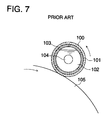
- an oil coating roller employed in the fixing oil coating apparatus as shown in Fig. 7, there has been disclosed an apparatus having a structure in that a hollow pipe-shaped metal core 101 is wound with felt cloth 100; in the inner hollow portion of the above-mentioned core 101, oil 102 is stored and the oil is supplied to the above-mentioned felt cloth through a plurality of holes 103 formed by penetrating the circumferential wall of the above-mentioned core 101 (refer to Japanese Utility Model Publication Open to Public Inspection 59-73762, etc.).
- the reference numeral 104 shows a rotation axis of an oil coating roller and the reference numeral 105 shows a fixing roller on which the oil is coated by the above-mentioned oil coating roller.
- the present invention has been accomplished and can prevent the clogging of the oil coating member and provides a fixing oil coating apparatus which can coat uniformly oil on a fixing roller.
- Another object of the present invention is to provide a fixing oil coating apparatus which can uniformly supply oil to an oil coating member such as felt, brush, etc. and can prevent oil drips in a sheet passing portion.
- the fixing oil coating apparatus of the present invention is a fixing oil coating apparatus to coat oil on the outer circumferential surface of a fixing roller to fix a toner image on a support material and is constructed in such a way that the construction of an oil coating roller is that the oil is impregnated and held in a cylindrical ceramic member having a number of exceedingly small pores, and a brush-shaped oil coating member is fixed to an outer circumference of the above-mentioned ceramic member and the oil is coated on the outer circumferential surface of the above-mentioned fixing roller, while the oil coating member of the oil coating roller is brought into contact with the above-mentioned fixing roller.
- the construction is that a regulating sheet is arranged between the above-mentioned ceramic member and oil coating member in order to regulate a supply of the oil from the above-mentioned ceramic member to the above-mentioned oil coating member.
- the structure is that a scraper is provided to scrape off the toner adhered to the tip portion of the brush of the above-mentioned oil coating member.
- the construction is that the oil is supplied to the above-mentioned scraper.
- the above-mentioned scraper is composed of an oil holding pad impregnated with the oil.
- Fig. 1 is a general schematic diagram showing a construction of a laser color printer to which the fixing oil coating apparatus according to the present invention is applied.
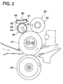
- Fig. 2 is a schematic diagram showing an embodiment of the fixing oil coating apparatus according to the present invention.
- Fig. 3 is a sectional view of an oil coating roller in the above-mentioned embodiment.
- Fig. 4 is a state diagram showing the relationship between an adhered toner and a oil pass in the above-mentioned embodiment.
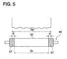
- Fig. 5 is a front view showing a sealing portion of the oil coating roller in the above-mentioned embodiment.
- Fig. 6 is a graph of an optimum circumferential velocity of an oil coating roller.
- Fig. 7 is a fragmentary sectional view of a conventional oil coating roller.
- Fig. 1 shows a construction of a laser color printer constructed employing a fixing device provided with the fixing oil coating apparatus according to the present invention.
- the printer constructed employing the fixing device is not limited to neither a laser type nor color.
- a photoreceptor drum 10 whose surface is coated with an OPC photosensitive layer is rotationally driven in one direction (in Fig. 1, clockwise direction), and after the charge is removed using charge elimination by a PCL (pre-charging) 11, the circumferential surface is uniformly charged by a charging device 12.
- an image exposure is performed by an image exposing means 13 according to an image signal.
- a laser beam emitted from a laser source not shown, is rotationally scanned by a polygon mirror 131; is led through a f ⁇ lens 132; is turned by a reflection mirror 133; is projected onto the circumferential surface of the photoreceptor drum 10 uniformly charged in advance and a latent image is formed on the surface of the photoreceptor drum 10.
- developing devices 14A to 14D which are loaded with each of developers composed of mixtures of each of yellow (Y), magenta (M), cyan (C) and black (K) toners with a carrier. And at first, the development of the first color (yellow Y) is carried out; after the development of the first color is finished, an image forming process of the second color (magenta M) is commenced; the photoreceptor 10 is uniformly charged again and a latent image is formed by the image exposing means 13 according to the image data of the second color. As to the third color (cyan C) and fourth color (black K), the similar image forming processes are carried out and the development of all the four colors are carried out on the circumferential surface of the photoreceptor drum 10.
- a recording sheet P (supporting material) transported by a sheet transport mechanism 22 from a sheet cassette 21 is advanced to a transfer device 30, wherein the multicolor toner images on the circumferential surface of the photoreceptor drum 10 is simultaneously transferred to the recording sheet P.
- the recording sheet is conveyed to a fixing device 23 composed of two rollers, upper and lower having a heater in the interior of at least one of rollers; the toners on the recording sheet P are fused and fixed between the fixing rollers by the application of heat and pressure and the recording sheet subjected to fixing is ejected from the apparatus by an sheet ejecting mechanism 24.
- a fixing device 23 composed of two rollers, upper and lower having a heater in the interior of at least one of rollers; the toners on the recording sheet P are fused and fixed between the fixing rollers by the application of heat and pressure and the recording sheet subjected to fixing is ejected from the apparatus by an sheet ejecting mechanism 24.
- Fig. 2 shows details of the construction of the above-mentioned fixing device 23.
- the construction is that after the transfer, the recording sheet P is transported from the left side in the figure against the upper and lower rollers 41 and 42. Heat and pressure is applied to the recording sheet P between the above-mentioned fixing rollers 41 and 42, and the toner is fixed and the recording sheet P is successively conveyed from the left side to the right side in the drawing.
- the above-mentioned upper fixing roller 41 is constructed so that it is rotationally driven counter clockwise by a motor, not shown, and for example, it is prepared by applying Teflon treatment to a cylindrical metal surface and has a heater for heating in the interior.
- the above-mentioned lower roller 42 is prepared, for example, by winding silicone rubber on a metal core and is brought into pressure contact with the above-mentioned upper fixing roller 41 and is driven clockwise in the drawing according to the rotation of the upper fixing roller 41.
- the construction is that a cleaning roller 43 and an oil coating roller 44 are additionally arranged to the above-mentioned upper fixing roller 41; the outer circumferential surface of the upper fixing roller 41 which has passed a nip portion (pressure contact portion) of the two fixing rollers 41 and 42 is, at first, subjected to removal of offset toner (toner adhered to the upper fixing roller 41, which is not fixed on a recording sheet P) by pressure contact with the above-mentioned cleaning roller 43; after the cleaning, oil is coated by contact with the above-mentioned oil coating roller 44 and is again led to the nip portion.
- the outer circumferential surface of the above-mentioned cleaning roller 43 is formed by silicone foam and the offset toner adhered to the above-mentioned upper fixing roller 41 is captured by the above-mentioned silicone foam and the offset toner is removed from the fixing roller 41.
- the above-mentioned cleaning roller 43 is composed of the cylindrical ceramic member 52 having a number of exceedingly small pores to which a metal rotation shaft is inserted, a regulating paper 53 composed of nonwoven fabric, etc. wound on the outer circumference of the ceramic member 52 and a brush-shaped oil coating member 54 which is wound on the outer circumference of the above-mentioned regulating sheet 53, and at both the ends in the axial direction of the above-mentioned ceramic member 52, metal flanges 55 and 56 are attached.
- the above-mentioned fixing roller 41 is brought into pressure contact with the oil coating member 54 of the above-mentioned oil coating roller 44 and the oil coating roller 44 is driven by the rotation of the fixing roller 41 so that the oil coating roller is frictionally rotated at the same circumferential speed.
- the oil coating roller 44 may be rotationally driven at the same or less circumferential speed as that of the fixing roller 41, while being subjected to rotational driving force of the motor which rotationally drives the fixing roller 41 through a gear, etc. which are provided coaxially with the above-mentioned oil coating roller 44.
- the above-mentioned ceramic member 52 is impregnated with oil (silicone oil) and functions as an oil holding layer for coating the oil on the above-mentioned upper fixing roller 41. And the oil impregnated in the above-mentioned ceramic member 52 is adjusted by the above-mentioned regulating paper 53, is supplied to the above-mentioned brush-shaped oil coating member 54 and is coated on the above-mentioned upper fixing roller 41 from the tip portion of the brush of the oil coating member 54.
- oil silicone oil
- the above-mentioned brush-shaped oil coating member 54 is such that, for example, a brush having a length of 2 to 3 mm is planted on a base for fixing the brush.
- the above-mentioned regulating paper 53 is adhered to the above-mentioned ceramic member 52 and the above-mentioned brush-shaped oil coating member 54 is adhered and fixed to the above-mentioned regulating paper 53.
- the above-mentioned adhered portion becomes an oil sealing portion, non-uniform supply of the oil is prevented, for example, by coating an adhesive in a spiral pattern and the like.
- the oil When constructed as mentioned above in that the oil is coated on the fixing roller 41 by the oil coating roller 44, the oil is impregnated and held in the ceramic member 52 having a number of exceedingly small pores. As a result, the oil can be supplied almost uniformly to the oil coating member 54 from the whole circumference of the ceramic member 52. Thus, the oil can be uniformly coated on the fixing roller 41. Furthermore, because the oil coating member 54 is shaped as a brush-like, clogging is hardly caused even if the offset toner is adhered, and the oil can be consistently coated on the fixing roller 41.
- the degradation in coating properties due to the offset toner can be avoided by rendering the oil coating member 54 brush-like.
- the adhered offset toner 71 adheres in a mat shape to the tip potion of the brush to likely cause a problem in the oil coating.
- a scraper is preferably provided which scrapes the offset toner adhered to the tips of the brush of the oil coating member 54.
- the reference numeral 72 represents the adhered position.
- an oil holding pad 62 in which a heat resistant felt 61 is impregnated with the oil is provided at the position where it is brought into contact with the brush of the above-mentioned oil coating member 54 while supported by a bracket 63.
- a plate made of resin may be employed. Even in the case of employing the above, a construction in that as the scraper, the oil stored in a tank is supplied to the resin plate can decrease remarkably the amount of the toner adhered to the tips of the brush.
- the scraper in which the oil is supplied to the resin plate, when constructed by employing the oil holding pad as described above, it is preferable that the scraper is conveniently constructed which can remarkably decrease the adhesion amount of the toner.
- the construction in that oil is impregnated and held in the cylindrical ceramic member having a number of exceedingly small pores makes it possible to supply uniformly the oil to the oil coating member and employing a member shaped like a brush as the above-mentioned oil coating member exhibits an advantage in the prevention of clogging of the oil coating member caused by the toner.
- the amount of the oil supplied to the oil coating member is adjusted to an optimum amount by the regulating paper arranged between the ceramic member and the oil coating member and an advantage is exhibited in that the above-mentioned supply amount and further excessive and deficient oil amount adhered to the fixing roller can be prevented.
- the scraper which makes it possible to decrease remarkably the amount of toner adhered to the tips of the brush of the oil coating member is readily constructed without employing an oil tank, etc.
- the above-mentioned ceramic member 52 has exceedingly small pores, as mentioned above, and the exceedingly small pores formed almost evenly around the whole circumference are capable of supplying almost uniformly the oil to the whole region in the axial direction of the oil coating member 54.
- the construction is that the circumferential surfaces of both ends in the axial direction of the above-mentioned ceramic member 52 undergo sealing and the length in the axial direction of the non-sealing portion of the above-mentioned ceramic member 52 is equal to the maximum sheet passing width or less.
- an adhesive for example, Si series adhesives
- the axial direction length D 0 of the above-mentioned non-sealing portion is equal to the maximum sheet passing width D P or less.
- the oil spot which is formed in such a way that the oil is supplied to the no sheet passing portion where no oil is consumed and accumulated; the accumulated oil moves to the sheet passing portion and the oil spot remains on a recording sheet.
- the boundary of the above-mentioned sealing layer 57 may be accorded with both the ends of the maximum sheet passing width D p .
- the oil supplied to the oil coating member 54 from the ceramic member 52 is penetrated to a portion where no oil is directly supplied from the ceramic member 52.
- the above-mentioned sealing boundary is positioned in the inside of both the ends of the above-mentioned maximum sheet passing width D p .
- the above-mentioned distance d is preferably adjusted in the range of 0 ⁇ d ⁇ 10 mm.
- a construction is that a driving force of a motor which rotationally drives the above-mentioned fixing roller 41 is transmitted to the above-mentioned oil coating roller 44 through a driving gear and the above-mentioned oil coating roller 44 is rotationally driven at a less circumferential speed than that of the fixing roller 41.
- a construction may be employed in that the oil coating roller 44 is driven by the rotation of the fixing roller 41 employing the frictional force at the pressure contact portion of the fixing roller 41 with the oil coating roller 44.
- a portion of the oil coating member 54 is collectively stained with the toner on account of the slip of the oil coating roller 44 and defects are caused on an image by spewing the adhered toner (phenomenon in which the toner adhered on the oil coating roller 44 is again adhered by the fixing roller 41), etc.
- the oil coating roller 44 is constructed so as to be rotationally driven, the above-mentioned slip can be prevented and staining collectively a portion of the oil coating member 54 with the toner can be avoided. Furthermore, the above-mentioned toner spewing tends to increase as the oil coating amount increases. Therefore, it is possible to avoid more effectively the above-mentioned toner spewing by decreasing the circumferential speed of the oil coating roller 44. However, when the circumferential speed is decreased excessively, the coating amount of oil becomes insufficient to degrade the degree of the recording sheet separation. Therefore, it is required to set the circumferential speed of the oil coating roller 44 at faster than the speed to secure the necessary oil coating amount (refer to Fig. 6.).
- the advantage is that the generation of oil drips on the oil coating member corresponding to the no sheet passing portion can be prevented by the sealing.
- the advantage is that by performing the sealing so that the sealing boundary is positioned in an inside of 0 to 10 mm from each of both the ends of the maximum sheet passing width, the oil can be securely coated on the fixing roller within the sheet passing width, while avoiding the formation of oil drips.
- the advantage is that the sealing for the ceramic member is conveniently performed by adhesive coating.
- the advantage is that by being rotationally driven so that the circumferential speed of the oil coating roller is less than that of the fixing roller, no degradation of oil coating properties occurs due to the slip of the oil coating roller against the fixing roller and a necessary amount of oil can be coated on the whole circumferential surface of the fixing roller.
Abstract
Description
Claims (6)
- A fixing oil coating apparatus comprising:(a) a fixing roller for fixing a toner image on a recording sheet; and(b) an oil coating roller includinga cylindrical porous member impregnated with oil therein, anda brush-shaped oil applying member fixed on an outer circumferential surface of the porous member,
wherein the brush-shaped oil applying member is brought into contact with an outer circumferential surface of the fixing roller so that the oil is coated to the fixing roller. - The fixing oil coating apparatus of claim 1, wherein the oil coating roller further comprises a regulating sheet provided between the porous member and the oil applying member for regulating a supplying amount of the oil from the porous member to the oil applying member.
- The fixing oil coating apparatus of claim 1 further comprising a scraper for scraping off toner adhered on tip ends of brush of the oil applying member.
- The fixing oil coating apparatus of claim 3, wherein the oil is supplied to the scraper.
- The fixing oil coating apparatus of claim 3, wherein the scraper includes an oil holding pad impregnated with the oil.
- The fixing oil coating apparatus of claim 1, wherein the porous member is made of ceramic.
Applications Claiming Priority (3)
| Application Number | Priority Date | Filing Date | Title |
|---|---|---|---|
| JP34125996 | 1996-12-20 | ||
| JP341259/96 | 1996-12-20 | ||
| JP34125996A JP3945547B2 (en) | 1996-12-20 | 1996-12-20 | Fixing oil application device |
Publications (3)
| Publication Number | Publication Date |
|---|---|
| EP0862095A2 true EP0862095A2 (en) | 1998-09-02 |
| EP0862095A3 EP0862095A3 (en) | 1999-01-27 |
| EP0862095B1 EP0862095B1 (en) | 2003-03-19 |
Family
ID=18344660
Family Applications (1)
| Application Number | Title | Priority Date | Filing Date |
|---|---|---|---|
| EP97122191A Expired - Lifetime EP0862095B1 (en) | 1996-12-20 | 1997-12-16 | Fixing oil coating apparatus |
Country Status (4)
| Country | Link |
|---|---|
| US (1) | US5937256A (en) |
| EP (1) | EP0862095B1 (en) |
| JP (1) | JP3945547B2 (en) |
| DE (1) | DE69719956D1 (en) |
Cited By (1)
| Publication number | Priority date | Publication date | Assignee | Title |
|---|---|---|---|---|
| US8897889B2 (en) | 2008-10-09 | 2014-11-25 | Boston Scientific Neuromodulation Corporation | Electrode design for leads of implantable electric stimulation systems and methods of making and using |
Citations (6)
| Publication number | Priority date | Publication date | Assignee | Title |
|---|---|---|---|---|
| JPS58215675A (en) * | 1982-06-09 | 1983-12-15 | Konishiroku Photo Ind Co Ltd | Heat roll fixation device |
| JPS6026971A (en) * | 1983-07-25 | 1985-02-09 | Konishiroku Photo Ind Co Ltd | Roller fixing device |
| US5253025A (en) * | 1990-11-28 | 1993-10-12 | Hitachi, Ltd. | Apparatus for fixing a toner image, fixing method and electrophotographic recording equipment |
| US5267004A (en) * | 1991-12-18 | 1993-11-30 | Eastman Kodak Company | Rotating wick for fusing apparatus having improved oil laydown |
| JPH05323822A (en) * | 1992-05-21 | 1993-12-07 | Sharp Corp | Fixing device |
| JPH0744052A (en) * | 1993-07-30 | 1995-02-14 | Toshiba Corp | Fixing device |
Family Cites Families (10)
| Publication number | Priority date | Publication date | Assignee | Title |
|---|---|---|---|---|
| JPS5820034B2 (en) * | 1975-04-30 | 1983-04-21 | 株式会社リコー | Fixing device of dry type electrophotographic copying machine |
| IT1091263B (en) * | 1977-12-01 | 1985-07-06 | Olivetti & Co Spa | MELTING ROLLER FIXING DEVICE FOR PERFECTED ELECTROPHOTOGRAPHIC COPIER MACHINE |
| JPS5836339B2 (en) * | 1978-09-19 | 1983-08-09 | ミノルタ株式会社 | Fixing device in electrophotographic copying machine |
| US4512650A (en) * | 1983-11-04 | 1985-04-23 | Eastman Kodak Company | Fuser apparatus having a uniform heat distribution |
| JPS619679A (en) * | 1984-06-25 | 1986-01-17 | Konishiroku Photo Ind Co Ltd | Fixing device with heat roller |
| US5047809A (en) * | 1988-01-26 | 1991-09-10 | Konica Corporation | Fixing apparatus with oil supply apparatus |
| EP0430677B1 (en) * | 1989-11-29 | 1994-09-21 | Canon Kabushiki Kaisha | Fixing device |
| US5200786A (en) * | 1991-11-26 | 1993-04-06 | Xerox Corporation | Donor brush ram system |
| US5802440A (en) * | 1995-06-30 | 1998-09-01 | Canon Kabushiki Kaisha | Cleaning apparatus for cleaning heat fixing member, heat fixing method and image forming method |
| US5732317A (en) * | 1995-11-02 | 1998-03-24 | Eastman Kodak Company | Rotating wick device |
-
1996
- 1996-12-20 JP JP34125996A patent/JP3945547B2/en not_active Expired - Fee Related
-
1997
- 1997-12-12 US US08/989,972 patent/US5937256A/en not_active Expired - Fee Related
- 1997-12-16 DE DE69719956T patent/DE69719956D1/en not_active Expired - Lifetime
- 1997-12-16 EP EP97122191A patent/EP0862095B1/en not_active Expired - Lifetime
Patent Citations (6)
| Publication number | Priority date | Publication date | Assignee | Title |
|---|---|---|---|---|
| JPS58215675A (en) * | 1982-06-09 | 1983-12-15 | Konishiroku Photo Ind Co Ltd | Heat roll fixation device |
| JPS6026971A (en) * | 1983-07-25 | 1985-02-09 | Konishiroku Photo Ind Co Ltd | Roller fixing device |
| US5253025A (en) * | 1990-11-28 | 1993-10-12 | Hitachi, Ltd. | Apparatus for fixing a toner image, fixing method and electrophotographic recording equipment |
| US5267004A (en) * | 1991-12-18 | 1993-11-30 | Eastman Kodak Company | Rotating wick for fusing apparatus having improved oil laydown |
| JPH05323822A (en) * | 1992-05-21 | 1993-12-07 | Sharp Corp | Fixing device |
| JPH0744052A (en) * | 1993-07-30 | 1995-02-14 | Toshiba Corp | Fixing device |
Non-Patent Citations (3)
| Title |
|---|
| PATENT ABSTRACTS OF JAPAN vol. 008, no. 068 (P-264), 30 March 1984 & JP 58 215675 A (KONISHIROKU SHASHIN KOGYO KK), 15 December 1983 * |
| PATENT ABSTRACTS OF JAPAN vol. 009, no. 148 (P-366), 22 June 1985 & JP 60 026971 A (KONISHIROKU SHASHIN KOGYO KK), 9 February 1985 * |
| PATENT ABSTRACTS OF JAPAN vol. 018, no. 149 (P-1708), 11 March 1994 & JP 05 323822 A (SHARP CORP), 7 December 1993 * |
Cited By (1)
| Publication number | Priority date | Publication date | Assignee | Title |
|---|---|---|---|---|
| US8897889B2 (en) | 2008-10-09 | 2014-11-25 | Boston Scientific Neuromodulation Corporation | Electrode design for leads of implantable electric stimulation systems and methods of making and using |
Also Published As
| Publication number | Publication date |
|---|---|
| JP3945547B2 (en) | 2007-07-18 |
| JPH10186924A (en) | 1998-07-14 |
| DE69719956D1 (en) | 2003-04-24 |
| US5937256A (en) | 1999-08-10 |
| EP0862095B1 (en) | 2003-03-19 |
| EP0862095A3 (en) | 1999-01-27 |
Similar Documents
| Publication | Publication Date | Title |
|---|---|---|
| JP2000075764A (en) | Process cartridge and image forming device | |
| EP0505168B1 (en) | Colour picture image formation devices | |
| US20100092205A1 (en) | Developing device and image forming device | |
| US5937256A (en) | Fixing oil coating apparatus, and fixing unit therewith | |
| JPH08265570A (en) | Image forming device | |
| EP1288731B1 (en) | Toner scattering suppressing apparatus and image forming apparatus | |
| JP4206314B2 (en) | Laser printer mixing roller and developing device | |
| US6965748B2 (en) | Drive roller for belt in an electrophotographic image forming apparatus | |
| JPH10186926A (en) | Fixing oil coating device | |
| EP0628894B1 (en) | Image forming apparatus | |
| JP3501640B2 (en) | Multicolor electrophotographic image forming apparatus | |
| JPS62209579A (en) | Fixing device | |
| JPH10213949A (en) | Primary electrostatic charging roller and laser printer/ cartridge | |
| JPH0723809Y2 (en) | Developing device for electrophotographic recording device | |
| KR100243237B1 (en) | Development apparatus in electrographic printer | |
| JP2003066797A (en) | Image forming apparatus and process cartridge | |
| JP3243363B2 (en) | Release agent coating device and fixing device provided with the same | |
| KR100477664B1 (en) | Liquid image developing apparatus | |
| KR200157961Y1 (en) | An image forming apparatus | |
| JP2000075647A (en) | Developing device, developing cartridge, and electrophotographic image forming device | |
| JPH02196267A (en) | Drying mechanism for adhesive transferring system | |
| JPS6333704B2 (en) | ||
| JP2001265123A (en) | Liquid material supply apparatus and image forming device | |
| JPH08334970A (en) | Developer supplying body, developing cartridge, image forming device and method for working developer supplying body | |
| JPH11143211A (en) | Developing device, process cartridge and image forming device |
Legal Events
| Date | Code | Title | Description |
|---|---|---|---|
| PUAI | Public reference made under article 153(3) epc to a published international application that has entered the european phase |
Free format text: ORIGINAL CODE: 0009012 |
|
| AK | Designated contracting states |
Kind code of ref document: A2 Designated state(s): DE FR GB |
|
| AX | Request for extension of the european patent |
Free format text: AL;LT;LV;MK;RO;SI |
|
| PUAL | Search report despatched |
Free format text: ORIGINAL CODE: 0009013 |
|
| AK | Designated contracting states |
Kind code of ref document: A3 Designated state(s): AT BE CH DE DK ES FI FR GB GR IE IT LI LU MC NL PT SE |
|
| AX | Request for extension of the european patent |
Free format text: AL;LT;LV;MK;RO;SI |
|
| 17P | Request for examination filed |
Effective date: 19990726 |
|
| AKX | Designation fees paid |
Free format text: DE FR GB |
|
| 17Q | First examination report despatched |
Effective date: 20010627 |
|
| GRAG | Despatch of communication of intention to grant |
Free format text: ORIGINAL CODE: EPIDOS AGRA |
|
| GRAG | Despatch of communication of intention to grant |
Free format text: ORIGINAL CODE: EPIDOS AGRA |
|
| GRAH | Despatch of communication of intention to grant a patent |
Free format text: ORIGINAL CODE: EPIDOS IGRA |
|
| GRAH | Despatch of communication of intention to grant a patent |
Free format text: ORIGINAL CODE: EPIDOS IGRA |
|
| GRAA | (expected) grant |
Free format text: ORIGINAL CODE: 0009210 |
|
| AK | Designated contracting states |
Designated state(s): DE FR GB |
|
| PG25 | Lapsed in a contracting state [announced via postgrant information from national office to epo] |
Ref country code: FR Free format text: LAPSE BECAUSE OF FAILURE TO SUBMIT A TRANSLATION OF THE DESCRIPTION OR TO PAY THE FEE WITHIN THE PRESCRIBED TIME-LIMIT Effective date: 20030319 |
|
| REG | Reference to a national code |
Ref country code: GB Ref legal event code: FG4D |
|
| REF | Corresponds to: |
Ref document number: 69719956 Country of ref document: DE Date of ref document: 20030424 Kind code of ref document: P |
|
| PG25 | Lapsed in a contracting state [announced via postgrant information from national office to epo] |
Ref country code: DE Free format text: LAPSE BECAUSE OF FAILURE TO SUBMIT A TRANSLATION OF THE DESCRIPTION OR TO PAY THE FEE WITHIN THE PRESCRIBED TIME-LIMIT Effective date: 20030621 |
|
| PLBE | No opposition filed within time limit |
Free format text: ORIGINAL CODE: 0009261 |
|
| STAA | Information on the status of an ep patent application or granted ep patent |
Free format text: STATUS: NO OPPOSITION FILED WITHIN TIME LIMIT |
|
| EN | Fr: translation not filed | ||
| 26N | No opposition filed |
Effective date: 20031222 |
|
| PGFP | Annual fee paid to national office [announced via postgrant information from national office to epo] |
Ref country code: GB Payment date: 20081210 Year of fee payment: 12 |
|
| GBPC | Gb: european patent ceased through non-payment of renewal fee |
Effective date: 20091216 |
|
| PG25 | Lapsed in a contracting state [announced via postgrant information from national office to epo] |
Ref country code: GB Free format text: LAPSE BECAUSE OF NON-PAYMENT OF DUE FEES Effective date: 20091216 |