EP0861636A2 - Device for positioning bone and/or bone fragments - Google Patents
Device for positioning bone and/or bone fragments Download PDFInfo
- Publication number
- EP0861636A2 EP0861636A2 EP98103359A EP98103359A EP0861636A2 EP 0861636 A2 EP0861636 A2 EP 0861636A2 EP 98103359 A EP98103359 A EP 98103359A EP 98103359 A EP98103359 A EP 98103359A EP 0861636 A2 EP0861636 A2 EP 0861636A2
- Authority
- EP
- European Patent Office
- Prior art keywords
- spherical
- fastening screw
- screw
- perforated plate
- recess
- Prior art date
- Legal status (The legal status is an assumption and is not a legal conclusion. Google has not performed a legal analysis and makes no representation as to the accuracy of the status listed.)
- Granted
Links
- 210000000988 bone and bone Anatomy 0.000 title claims description 31
- 239000012634 fragment Substances 0.000 title claims description 12
- 230000000295 complement effect Effects 0.000 claims description 5
- 239000000463 material Substances 0.000 claims description 5
- 239000007943 implant Substances 0.000 claims description 4
- 229910000831 Steel Inorganic materials 0.000 claims description 2
- 239000010959 steel Substances 0.000 claims description 2
- OKTJSMMVPCPJKN-UHFFFAOYSA-N Carbon Chemical compound [C] OKTJSMMVPCPJKN-UHFFFAOYSA-N 0.000 claims 1
- 229910052799 carbon Inorganic materials 0.000 claims 1
- 210000000245 forearm Anatomy 0.000 claims 1
- 239000002184 metal Substances 0.000 claims 1
- 229920003023 plastic Polymers 0.000 claims 1
- 239000004033 plastic Substances 0.000 claims 1
- 230000006378 damage Effects 0.000 description 4
- 208000027418 Wounds and injury Diseases 0.000 description 3
- 208000014674 injury Diseases 0.000 description 3
- 238000004519 manufacturing process Methods 0.000 description 3
- 210000005036 nerve Anatomy 0.000 description 2
- RTAQQCXQSZGOHL-UHFFFAOYSA-N Titanium Chemical compound [Ti] RTAQQCXQSZGOHL-UHFFFAOYSA-N 0.000 description 1
- 241001105097 Trox Species 0.000 description 1
- 230000001154 acute effect Effects 0.000 description 1
- 229910045601 alloy Inorganic materials 0.000 description 1
- 239000000956 alloy Substances 0.000 description 1
- 230000009286 beneficial effect Effects 0.000 description 1
- 238000010276 construction Methods 0.000 description 1
- 238000011161 development Methods 0.000 description 1
- 230000018109 developmental process Effects 0.000 description 1
- 238000000034 method Methods 0.000 description 1
- 230000003716 rejuvenation Effects 0.000 description 1
- 229910052719 titanium Inorganic materials 0.000 description 1
- 239000010936 titanium Substances 0.000 description 1
- 230000007704 transition Effects 0.000 description 1
Images


Classifications
-
- A—HUMAN NECESSITIES
- A61—MEDICAL OR VETERINARY SCIENCE; HYGIENE
- A61B—DIAGNOSIS; SURGERY; IDENTIFICATION
- A61B17/00—Surgical instruments, devices or methods, e.g. tourniquets
- A61B17/56—Surgical instruments or methods for treatment of bones or joints; Devices specially adapted therefor
- A61B17/58—Surgical instruments or methods for treatment of bones or joints; Devices specially adapted therefor for osteosynthesis, e.g. bone plates, screws, setting implements or the like
- A61B17/68—Internal fixation devices, including fasteners and spinal fixators, even if a part thereof projects from the skin
- A61B17/70—Spinal positioners or stabilisers ; Bone stabilisers comprising fluid filler in an implant
- A61B17/7001—Screws or hooks combined with longitudinal elements which do not contact vertebrae
- A61B17/7002—Longitudinal elements, e.g. rods
- A61B17/701—Longitudinal elements with a non-circular, e.g. rectangular, cross-section
-
- A—HUMAN NECESSITIES
- A61—MEDICAL OR VETERINARY SCIENCE; HYGIENE
- A61B—DIAGNOSIS; SURGERY; IDENTIFICATION
- A61B17/00—Surgical instruments, devices or methods, e.g. tourniquets
- A61B17/56—Surgical instruments or methods for treatment of bones or joints; Devices specially adapted therefor
- A61B17/58—Surgical instruments or methods for treatment of bones or joints; Devices specially adapted therefor for osteosynthesis, e.g. bone plates, screws, setting implements or the like
- A61B17/68—Internal fixation devices, including fasteners and spinal fixators, even if a part thereof projects from the skin
- A61B17/70—Spinal positioners or stabilisers ; Bone stabilisers comprising fluid filler in an implant
- A61B17/7001—Screws or hooks combined with longitudinal elements which do not contact vertebrae
- A61B17/7002—Longitudinal elements, e.g. rods
- A61B17/7004—Longitudinal elements, e.g. rods with a cross-section which varies along its length
- A61B17/7007—Parts of the longitudinal elements, e.g. their ends, being specially adapted to fit around the screw or hook heads
-
- A—HUMAN NECESSITIES
- A61—MEDICAL OR VETERINARY SCIENCE; HYGIENE
- A61B—DIAGNOSIS; SURGERY; IDENTIFICATION
- A61B17/00—Surgical instruments, devices or methods, e.g. tourniquets
- A61B17/56—Surgical instruments or methods for treatment of bones or joints; Devices specially adapted therefor
- A61B17/58—Surgical instruments or methods for treatment of bones or joints; Devices specially adapted therefor for osteosynthesis, e.g. bone plates, screws, setting implements or the like
- A61B17/68—Internal fixation devices, including fasteners and spinal fixators, even if a part thereof projects from the skin
- A61B17/70—Spinal positioners or stabilisers ; Bone stabilisers comprising fluid filler in an implant
- A61B17/7058—Plates mounted on top of bone anchor heads or shoulders
-
- A—HUMAN NECESSITIES
- A61—MEDICAL OR VETERINARY SCIENCE; HYGIENE
- A61B—DIAGNOSIS; SURGERY; IDENTIFICATION
- A61B17/00—Surgical instruments, devices or methods, e.g. tourniquets
- A61B17/56—Surgical instruments or methods for treatment of bones or joints; Devices specially adapted therefor
- A61B17/58—Surgical instruments or methods for treatment of bones or joints; Devices specially adapted therefor for osteosynthesis, e.g. bone plates, screws, setting implements or the like
- A61B17/68—Internal fixation devices, including fasteners and spinal fixators, even if a part thereof projects from the skin
- A61B17/70—Spinal positioners or stabilisers ; Bone stabilisers comprising fluid filler in an implant
- A61B17/7001—Screws or hooks combined with longitudinal elements which do not contact vertebrae
- A61B17/7002—Longitudinal elements, e.g. rods
- A61B17/7011—Longitudinal element being non-straight, e.g. curved, angled or branched
-
- A—HUMAN NECESSITIES
- A61—MEDICAL OR VETERINARY SCIENCE; HYGIENE
- A61B—DIAGNOSIS; SURGERY; IDENTIFICATION
- A61B17/00—Surgical instruments, devices or methods, e.g. tourniquets
- A61B17/56—Surgical instruments or methods for treatment of bones or joints; Devices specially adapted therefor
- A61B17/58—Surgical instruments or methods for treatment of bones or joints; Devices specially adapted therefor for osteosynthesis, e.g. bone plates, screws, setting implements or the like
- A61B17/68—Internal fixation devices, including fasteners and spinal fixators, even if a part thereof projects from the skin
- A61B17/70—Spinal positioners or stabilisers ; Bone stabilisers comprising fluid filler in an implant
- A61B17/7001—Screws or hooks combined with longitudinal elements which do not contact vertebrae
- A61B17/7035—Screws or hooks, wherein a rod-clamping part and a bone-anchoring part can pivot relative to each other
Definitions
- the invention relates to a device for positioning and Fixation of bones and / or bone fragments after the Preamble of claim 1.
- Aesculap is a spine system with the name SOCON known in which two screws over intermediate elements are connected by means of a threaded rod.
- the intermediate elements are designed so that they are on the one hand on the Threaded rod can be moved axially by turning and on the other hand, around an axis that is perpendicular to the screw axis and is pivoted perpendicular to the axis of the threaded rod can be.
- This spine system has the disadvantage that when Swivel the screws around the axis of the threaded rods at the same time moving the screws along the threaded rod occurs. Except when swiveling the screw around axis perpendicular to the screw and threaded rod axis for example, when using two screws, the are not connected via the threaded rod, to pivot a screw without at the same time Change the distance between the two screws.
- the foregoing spinal system becomes transpedicular Used screws that have a conventional thread runout and therefore have no screw-in depth stop. This can be the same as the presence of hard surface edges lead to injuries on the connecting parts.
- This system can be freely pivoted around a ball head Screws can be clamped in the desired position. There however, the clamping is not in the direction of the axis of symmetry Clamping takes place, tilting of the clamping piece as well of the threaded rod occur, creating tension in the device be introduced, which are transferred to the bones.
- the object of the invention is therefore a device for positioning and fixing bones and / or bone fragments to create with the possible in all device-related Bones and / or bone fragments remained the same Strength without the occurrence of undesirable prestresses are fixable and positionable, with the device with a small construction volume, the risk of injury is minimized and not pre-assembling individual parts of the device should be required.
- this object is in a device for positioning and fixing bones and / or bone fragments solved by the features in claim 1.
- Beneficial Developments are the subject of claim 1 directly or indirectly related claims.
- These holding devices are on a prosthesis plate serving perforated plate having at least two holes can be fastened and fixed using a lock nut, that the holding devices slidably held in the perforated plate Align perpendicular to the perforated plate.
- Holding device not only eliminates pre-assembly, but in particular there is no assembly of the holding device forming parts by the operating doctor during the operation.
- the perforated plate has at least two elongated holes this slidable with respect to the holding device, so that no pre-tension when fixing the screws to the perforated plate occur over the screws in the bones and / or bone fragments would be introduced.
- the fastening screws preferably have a cylindrical core with a screw thread, that has a constant outside diameter.
- the outer flank ends of the screw threads are very rounded, so that on the one hand due to the screw shape and on the other hand due to the flank ends, the bones are stressed as little as possible will. It can also advantageously the screw-in depth of the screws can be corrected at any time if necessary will.
- the free ends of the fastening screws rounded.
- the screws on upper end of the screw thread optionally one cylindrical approach, through which on the one hand the maximum Screw-in depth is limited and on the other hand a better one Load distribution in the screw head support is realized.
- the device has a head part of the fastening screw Recess with a truncated cone and an adjoining one spherical area, being in the spherical Area a conical end part of a connecting part is used and by the frustoconical area the possible swivel range is fixed. So is the screw around the spherical end part of the connecting part rotatable and swiveling.
- the spherical end part of the connecting part goes into one stretchable shaft part over, which in turn in a threaded part ends with an external thread.
- an opening preferably designed as an elongated hole Perforated plate inserted the stretchable shaft of the connecting part and on the threaded part is preferably with a Screwed on fine thread profiled nut.
- the first Line of the connecting rod between the fastening screw and modified the perforated plate according to the invention in such a way that the screw at an adjustable distance from the perforated plate can be fixed.
- a spherical Head part of the fastening screw in which the opposite Embodiment described above, no recesses is provided in a complementary to the spherical head part Area stored inside a sleeve.
- the sleeve on that facing away from the fastening screw End a cylindrical recess with an internal thread in which the connecting part designed as a threaded rod is screwed in. Furthermore, the sleeve is to be attached a tool, for example a wrench, outside formed as a hexagon. It is also a threaded rod trained connecting part by means of two nuts for example, adjustable in height in an elongated hole in the perforated plate and fixable in this position.
- the distance between the perforated plate and the fastening screw over the threaded rod is therefore particularly advantageous.
- the threaded rod on the headboard the end facing the fastening screw one of the curvature of the spherical head part corresponding concave recess on.
- screw head and the nut can also specify in the edges of the elongated holes for example, conical or spherical hollows be.
- both embodiments according to the invention provided all or some of the contact surfaces statistically between the individual elements of the device to be profiled or provided with fine transverse grooves. Consequently there is a secure hold between the individual elements, since the friction is increased by positive locking.
- perforated plates are of any shape and any any number of arranged and shaped elongated holes conceivable.
- All elements of the invention are preferably Device made of the same material, such as Implant steels according to DIN 17443, such as 1.4428 or 1.4461, or from special alloys such as CoCrMo, or grade 4 or 5 titanium, such as TI6-A14-V.
- the device according to the invention has the additional Advantage of having only a small number of tools is required, which is also easy to use. It deals these are primarily standard tools.
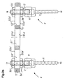
- Fig.1b is a serving as a prosthesis plate, in section shown perforated plate 5, for example in Fig.1b has three slots 50 to 52.
- the two outer slots 50 and 52 of the perforated plate 5 is one Holding device 4 used, the essential elements in Fig.1b from top to bottom, a lock nut 3 and a Connecting part 2 and a fastening screw 1 are.
- the Fastening screws 1 of the two holding devices 4 are in vertebrae previously indicated schematically by an operator 24 trained channels, not shown in FIG. 1b screwed in.
- FIG. 1a a first is preferred Embodiment of the holding device 4 based on a Sectional view along the line I-I described in Fig.1b.
- 1a shows the fastening screw 1 of the holding device 4 a cylindrical core with a screw thread 11 which has a constant outside diameter.
- the Flanks of the screw thread 11 have rounded flank ends 12 on.
- the lower free end 13 of the screw 1 in FIG. 1 is also rounded.
- annular extension 14 which is preferably cylindrical is formed and whose outer diameter is larger than the outer diameter of the screw thread 11.
- the annular extension 14 merges into a head part 15, the outer dimension of which is larger than that of the annular extension and is preferably designed on the outside as a hexagon 15 1 in order to be able to attach a suitable tool, for example a commercially available open-ended spanner.
- the head part 15 has a spherical recess 15 2 .
- the spherical recess 15 2 merges into a frustoconical recess 15 3 which is symmetrical with the dashed center axis of the screw 11 and which is open at the top in FIG.
- the smaller radius of the frustoconical recess 15 3 is adjacent to the upper part of the spherical recess 15 2 .
- the extensions of the frustoconical recess 15 3 shown in dashed lines in the sectional view in FIG. 1a preferably include an acute angle ⁇ of 30 ° -40 °.
- the hexagon 15 1 of the head part 15 merges into a spherical shell-shaped section 15 4 .
- the diameter of the spherical recess 15 2 in the head part 15 is larger than the adjacent smaller diameter of the frustoconical recess 15 3 .
- an undercut occurs at the transition area between the frustoconical recess 15 3 and the spherical recess 15 2 .
- a spherical end part 21 of the connecting part 2 complementary to the spherical recess 15 2 is inserted.
- the end facing away from the spherical end part 21 of the connecting part 2 is of circular cylindrical design and is provided with an external thread 22 which is preferably designed as a fine thread profile.
- the head part 15 has to be manufactured from two individual parts for manufacturing reasons.
- the dividing line between the two individual parts forming the head part 15 can be, for example, the dividing line entered with dash-dot lines.
- this part After inserting the spherical end part 21 of the connecting part 2 into the lower part of the head part which forms a unit with the fastening screw 1, this part is firmly connected to the part of the head part 15 shown above the dash-dotted line, for example welded or possibly also glued, so that the Head part 15 then forms a unit shown in Fig.1a with the fastening screw.
- the connecting part 2 in the head part 15 can be rotated on the one hand about the axis represented by the broken line and on the other hand in the area defined by the frustoconical recess 15 3 also pivotable with respect to the center axis shown in dashed lines.
- the angular range in which the connecting part 2 can be pivoted relative to the fastening screw 1 corresponds to the angular range designated by ⁇ in FIG. 1a and is in the order of magnitude of 30 ° to 35 in the embodiment of FIG. 1a °.
- the lock nut 3 preferably as a hex nut is formed, one of the fine thread profiling of the External thread 22 of the connecting part 2 corresponding thread and on the lower side in Fig.1a an annular approach 31 with a chamfer 32.
- Fig.1b which is a sectional view along the line II-II 1a is the perforated plate serving as a prosthesis plate 5 partially shown in section.
- the perforated plate 5 in FIG. 1b has three elongated holes 50 to 52 on.
- the upper edges 50b to 52b in FIG. 1b are suitable for the chamfer 32 of the annular projection 31 of the lock nut 3 beveled.
- edges 50a to 52a of the elongated holes 50 to 52 are rounded so that their rounding corresponds to the spherical end section 15 4 of the head part 15 at the upper end of the fastening screw 1.
- the radius of the concave edge regions 50a to 52a of the three elongated holes 50 to 52 thus corresponds to the radius of the spherical section 15 4 of the head part 15. Due to the concave design of the edge regions 50a to 52a, a corresponding tilting or inclination of the fastening screws 1 with respect to the as Perforated plate serving for prosthesis plate 5 (see Fig.1c).
- the perforated plate serving as a prosthesis plate is attached to a pedicle as follows: First, the surgeon inserts a pedicle channel into a vertebra 24. Appropriately, a thread corresponding to the screw thread 11 of the fastening screw 1 to be inserted should also be cut in the pedicle channel. By attaching a tool, for example an open-ended wrench, to the hexagon 15 1 on the head part 15 of the fastening screw 1, this is screwed in together with the connecting part 2 inserted into the head part 15 so that the head part 15 and the connecting part 2 protruding therefrom in the correct altitude.
- a tool for example an open-ended wrench
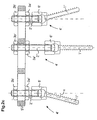
- a second preferred one is given below Embodiment according to the invention described.
- a holding device 4 ' which consists of a Fixing screw 1 'and a threaded rod Connecting part 2 ', nuts 3a' and 3b 'as well a perforated plate 5 is shown.
- the area of the fastening screw provided with a screw thread 11 ' 1 ' corresponds in principle to the corresponding one Area of the mounting screw 1 in Fig.1a and therefore points also has a cylindrical core on which a screw thread 11 'is provided with a constant outer diameter.
- the flank ends 12 ' like the free end 13', are rounded.
- the outer diameter of the outer diameter corresponds to the screw thread 11 '.
- the ring-shaped Approach 14 ' goes into a spherical head part 15' about, which is received in a sleeve 6 '.
- the sleeve 6 ' consists of manufacturing reasons two sleeve parts 6a 'and 6b', which are firmly connected are.
- the lower sleeve part 6b 'in FIG. 2a has one through recess, whose lower end in Fig.2a frustoconical area 60 '.
- the upper sleeve part 6a 'in FIG. 2a which is on the common Contact surface 6ab 'is connected to the sleeve part 6b', in turn has a continuous recess, which by a cylindrical region 62 'in FIG a cylindrical area provided with an internal thread 63 'passes over.
- the sleeve part 6a ' is preferably in the form of a hexagon trained to use an appropriate tool, if necessary to be able to attach a cranked spanner.
- the thread the internal thread which is preferably designed as a fine thread corresponds to the sleeve part 6a '.
- the threaded rod 2 ' points at the spherical head part 15 'of the fastening screw 1 'adjacent end 21' a concave bulge whose curvature is that of the spherical head part Corresponds to 15 '.
- the opposite end 20 'of the threaded rod 2 ' is rounded.
- FIG. 2a In the upper end part of the threaded rod 2 'in FIG. 2a is also a symmetrical to the dashed center axis Recess 24 'is provided, which is preferably a shape corresponding to an Allen key or TROX key having.
- a lower one in FIG. 2a is placed on the threaded rod 2 ' Screwed nut 3a '.
- the threaded rod 2 'through a in Fig. 2a unspecified slot of a perforated plate 5 'is inserted on the free upper end of the threaded rod 2 'screwed the nut 3b', which then at least the threaded rod 2 'is fixed with respect to the perforated plate 5'.
- Fig.2b which is a sectional view of the second preferred Embodiment along the line IV-IV in Fig. 2a is two fastening screws 1 'over sleeves 6', threaded rods 2 'and two nuts 3a' and 3b 'with the perforated plate 5' connected.
- the perforated plate 5 ' has three elongated holes in Fig.2b 50 'to 52', the middle areas of which are rectangular in plan view are and their end regions in plan view each are semicircular. Therefore, the nuts 3a 'and 3b' simple nuts, each on the Perforated plate 5 'facing side just executed and only are chamfered on the outside. To simplify the manufacture of the nuts, The nuts are so that they are confusion-free Completely identical as hexagon nuts.
- the edges 50a 'to 52b' can, for example, as described with reference to Fig.1a.
- the nuts 3a 'and 3b' must also fall open at least one side which corresponds to the chamfering of the edges 50a 'to 52a' or 50b 'to 52b' have a corresponding shape.
- Fig.2c of the second embodiment correspond to the device according to the invention the two outer brackets attached to the perforated plate 5 ' 4 'including the angle of inclination shown ⁇ of the representation in Fig.1c.
- Fig.1c in Fig.2c is a third, shown in the middle Fixing device fixed to the perforated plate 5 ', in which the dashed center axis of the fastening screw 1 ' and the threaded rod 2 'are aligned.
- Fig. 2c also shows that the second preferred Embodiment of the invention the length of the threaded rods 2 'or 2' 'can be freely selected. This is also the Location of the respective mounting device 4 'with respect to Perforated plate 5 'or the distance between the underside of the sleeve 6' from the perforated plate 5 'according to the respective circumstances selectable and adaptable. A fine adjustment or precise setting of the position is then particularly through given the choice of the position of the lower screws 3a 'in FIG. 2c.
- FIG.3a shows a perforated plate 5a, which has three elongated holes 6a, 6b and 6c, that on a dashed center line are arranged and, as also shown in Fig.3a, different Can have lengths.
- FIG. 3b shows a T-shaped perforated plate 5b, which two elongated holes arranged in series and of the same size in FIG. 3b 7b and 7c and one arranged perpendicular to them, for example Has elongated hole 7a.
- 3c shows an arcuate perforated plate 5c, for example three elongated holes 8a, 8b and 8c of the same size has along a dashed curved line are aligned.
- Fig.3d an L-shaped perforated plate 5d is shown two arranged in a row in series, the same in Fig.3d large slots 9b, 9c and a slot perpendicular to these 9a.
- any other combinations of are different dimensioned elongated holes conceivable.
- the in Fig.3a to Perforated plates shown in 3d are shown as flat in themselves.
- the individual perforated plates can also be preformed in this way be, for example, their two end areas upwards are angled or one end area down and the other is angled upwards or only one end area at all is angled or cranked while the other end region has just been executed.
- one of the fastening screw 1 is enlarged Fig.1a corresponding mounting screw 1 '' and one of the Fastening screw 1 'in Fig.2a corresponding fastening screw 1 '' 'reproduced.
Abstract
Description
Die Erfindung betrifft eine Vorrichtung zum Positionieren und
Fixieren von Knochen und/oder knochenfragmenten nach dem
Oberbegriff des Anspruchs 1.The invention relates to a device for positioning and
Fixation of bones and / or bone fragments after the
Preamble of
Von der Firma Aesculap ist ein Wirbelsäulensystem mit dem Namen SOCON bekannt, bei welchem zwei Schrauben über Zwischenelemente mittels einer Gewindestange verbunden sind. Die Zwischenelemente sind so ausgebildet, daß sie einerseits auf der Gewindestange durch Drehen axial verschoben werden können und andererseits um eine Achse, die senkrecht zur Schraubenachse und senkrecht zur Achse der Gewindestange ist, verschwenkt werden können.From the company Aesculap is a spine system with the name SOCON known in which two screws over intermediate elements are connected by means of a threaded rod. The intermediate elements are designed so that they are on the one hand on the Threaded rod can be moved axially by turning and on the other hand, around an axis that is perpendicular to the screw axis and is pivoted perpendicular to the axis of the threaded rod can be.
Dieses Wirbelsäulensystem weist den Nachteil auf, daß beim Schwenken der Schrauben um die Achse der Gewindestangen gleichzeitig ein Verschieben der Schrauben entlang der Gewindestange auftritt. Außer beim Schwenken der Schraube um die zur Schrauben- und zur Gewindestangenachse senkrechte Achse ist es beispielsweise beim Verwenden von zwei Schrauben, die über die Gewindestange miteinander verbunden sind, nicht möglich, eine Schraube zu verschwenken, ohne gleichzeitig den Abstand zwischen den beiden Schrauben zu verändern.This spine system has the disadvantage that when Swivel the screws around the axis of the threaded rods at the same time moving the screws along the threaded rod occurs. Except when swiveling the screw around axis perpendicular to the screw and threaded rod axis for example, when using two screws, the are not connected via the threaded rod, to pivot a screw without at the same time Change the distance between the two screws.
Außerdem werden bei vorstehendem Wirbelsäulensystem transpedikuläre Schrauben verwendet, die einen herkömmlichen Gewindeauslauf und somit keinen Einschraubtiefenanschlag aufweisen. Dies kann ebenso wie das Vorhandensein harter Oberflächenkanten an den Verbindungsteilen zu Verletzungen führen.In addition, the foregoing spinal system becomes transpedicular Used screws that have a conventional thread runout and therefore have no screw-in depth stop. This can be the same as the presence of hard surface edges lead to injuries on the connecting parts.
Da die verwendeten Schrauben ferner spitz enden, können beispielsweise beim Austritt der Schraube aus einem Knochen anliegendes Gewebe oder Nerven verletzt werden.Since the screws used also end pointedly, for example when the screw emerges from a bone Tissue or nerves are injured.
Des weiteren handelt es sich bei vorstehend beschriebenem Wirbelsäulensystem um eine relativ voluminöse Vorrichtung, deren Handhabung schwierig ist und eine relativ hohe Anzahl an Montagewerkzeugen erforderlich macht. Furthermore, it is the one described above Spine system around a relatively voluminous device, their handling is difficult and a relatively high number on assembly tools.
Ein weiteres Wirbelsäulensystem zum Positionieren und Fixieren von Wirbelkörpern ist von der Firma Boehringer unter dem Namen DEPUY MOTECH bekannt, bei dem ebenfalls Schrauben mit spitzen Enden und harten Gewindekanten verwendet werden, wodurch, wie vorstehend beschrieben, Verletzungen hervorgerufen werden können. Ferner sind die Gewinde nicht für einen Einsatz bei Knochen optimiert. Die Schrauben weisen ebenso wie die des Wirbelsäulensystems SOCON keinen Einschraubtiefenanschlag auf.Another spine system for positioning and fixing of vertebral bodies is from Boehringer under the Name DEPUY MOTECH known, which also has screws with pointed ends and hard thread edges are used, which, injury as described above can be. Furthermore, the threads are not for use optimized for bones. The screws point as well that of the SOCON spine system does not have a screw-in depth stop on.
Die bei diesem System um einen Kugelkopf frei schwenkbaren Schrauben können in der gewünschten Lage geklemmt werden. Da die Klemmung jedoch nicht in der Symmetrieachsen-Richtung des Klemmstücks erfolgt, kann ein Verkippen des Klemmstücks sowie des Gewindestabs auftreten, wodurch Spannungen in die Vorrichtung eingebracht werden, die sich auf die Knochen übertragen.This system can be freely pivoted around a ball head Screws can be clamped in the desired position. There however, the clamping is not in the direction of the axis of symmetry Clamping takes place, tilting of the clamping piece as well of the threaded rod occur, creating tension in the device be introduced, which are transferred to the bones.
Bei beiden vorstehend beschriebenen Vorrichtungen ist es erforderlich, einzelne Elemente der Vorrichtung vorzumontieren. Dies schränkt die Handhabbarkeit der einzelnen Elemente erheblich ein.With both devices described above, it is necessary pre-assemble individual elements of the device. This considerably limits the handling of the individual elements a.
Aufgabe der Erfindung ist es daher, eine Vorrichtung zum Positionieren und Fixieren von Knochen und/oder Knochenfragmenten zu schaffen, mit der in allen vorrichtungsbedingt möglichen Lagen Knochen und/oder Knochenfragmente bei gleichbleibender Festigkeit ohne Auftreten unerwünschter Vorspannungen fixierbar und positionierbar sind, wobei mit der Vorrichtung bei geringem Bauvolumen die Verletzungsgefahr minimiert werden und ein Vormontieren einzelner Vorrichtungsteile nicht erforderlich sein soll.The object of the invention is therefore a device for positioning and fixing bones and / or bone fragments to create with the possible in all device-related Bones and / or bone fragments remained the same Strength without the occurrence of undesirable prestresses are fixable and positionable, with the device with a small construction volume, the risk of injury is minimized and not pre-assembling individual parts of the device should be required.
Ferner ist es Aufgabe der Erfindung, zusätzlich ein Ausrichten der Knochen und/oder Knochenfragmente in einer Höhenlage zueinander zu ermöglichen. It is also an object of the invention to additionally align the bones and / or bone fragments at an altitude to enable each other.
Gemäß der Erfindung ist diese Aufgabe bei einer Vorrichtung
zum Positionieren und Fixieren von Knochen und/oder Knochenfragmenten
durch die Merkmale im Anspruch 1 gelöst. Vorteilhafte
Weiterbildungen sind Gegenstand der auf Anspruch 1 unmittelbar
oder mittelbar rückbezogenen Ansprüche.According to the invention, this object is in a device
for positioning and fixing bones and / or bone fragments
solved by the features in
Erfindungsgemäß weist die Vorrichtung zum Positionieren und Fixieren von Knochen und/oder Knochenfragmenten Haltevorrichtungen auf, die jeweils aus einer Befestigungsschraube und einem an dieser schwenkbar gehalterten Verbindungsteil bestehen. Diese Haltevorrichtungen sind an einer als Protheseplatte dienenden, mindestens zwei Löcher aufweisenden Lochplatte mittels einer Sicherungsmutter so befestigbar und fixierbar, daß sich die in der Lochplatte verschiebbar gehalterten Haltevorrichtungen senkrecht zur Lochplatte ausrichten.According to the invention, the device for positioning and Fixing bones and / or bone fragments on, each consisting of a fastening screw and exist on this pivotally connected connecting part. These holding devices are on a prosthesis plate serving perforated plate having at least two holes can be fastened and fixed using a lock nut, that the holding devices slidably held in the perforated plate Align perpendicular to the perforated plate.
Aufgrund dieser Ausbildung der gemäß der Erfindung vorgesehenen Haltevorrichtung entfällt nicht nur ein Vormontieren, sondern insbesondere entfällt ein Zusammensetzen der die Haltevorrichtung bildenden Teile durch den operierenden Arzt während der Operation. Nachdem die einzelnen Befestigungsschrauben der benötigten Haltevorrichtungen in die vorbereiteten Pedikelkanäle, in welche zweckmäßigerweise auch ein dem Schraubgewinde der Befestigungsschrauben entsprechendes Gewinde geschnitten ist, eingeschraubt sind, brauchen die Halterungsteile lediglich noch durch die Löcher, vorzugsweise in Form von Langlöchern der als Protheseplatte dienenden Lochplatte gesteckt zu werden und die Sicherungsschrauben aufgeschraubt und mit einem Drehmomentschlüssel angezogen werden.Because of this design the provided according to the invention Holding device not only eliminates pre-assembly, but in particular there is no assembly of the holding device forming parts by the operating doctor during the operation. After the individual fastening screws of the required fixtures in the prepared ones Pedicle channels, in which also a conveniently Screw thread of the fastening screws corresponding thread is cut, screwed in, need the bracket parts only through the holes, preferably in Form of elongated holes of the perforated plate serving as a prosthesis plate to be inserted and the locking screws screwed on and tightened with a torque wrench.
Da die Lochplatte mindestens zwei Langlöcher aufweist, ist diese bezüglich der Haltevorrichtung verschiebbar, so daß beim Fixieren der Schrauben an der Lochplatte keine Vorspannungen auftreten, die über die Schrauben in die Knochen und/oder Knochenfragmente eingeleitet würden.Since the perforated plate has at least two elongated holes this slidable with respect to the holding device, so that no pre-tension when fixing the screws to the perforated plate occur over the screws in the bones and / or bone fragments would be introduced.
Aufgrund der in den Lochplatten vorgesehen Langlöcher können beim Verbinden von zwei oder mehr Schrauben über eine Lochplatte diese einzeln zueinander verschoben werden. Da das Verschwenken der Schrauben unabhängig vom Verschieben der Haltevorrichtungen in den Langlöchern der Lochplatte erfolgt, wird die Handhabbarkeit der Vorrichtung erleichtert und kann bezüglich der Knochen und/oder Knochenfragmente in die erforderliche Höhe (beispielsweise zum Repositionieren) gebracht, wenn es gewünscht oder erforderlich ist.Due to the elongated holes provided in the perforated plates when connecting two or more screws via a perforated plate these are individually shifted to each other. Since that Swiveling the screws regardless of moving the Holding devices in the elongated holes of the perforated plate, the handling of the device is facilitated and can regarding the bones and / or bone fragments in the required Height (for example to be repositioned), if desired or required.
Erfindungsgemäß weisen die Befestigungsschrauben vorzugsweises einen zylindrischen Kern mit einem Schraubgewinde auf, das einen konstanten Außendurchmesser hat. Zusätzlich sind die äußeren Flankenenden der Schraubgewinde stark abgerundet, so daß einerseits aufgrund der Schraubenform und andererseits aufgrund der Flankenenden die Knochen möglichst wenig beansprucht werden. Ferner kann zusätzlich in vorteilhafter Weise die Einschraubtiefe der Schrauben bei Bedarf jederzeit nachkorrigiert werden.According to the invention, the fastening screws preferably have a cylindrical core with a screw thread, that has a constant outside diameter. In addition are the outer flank ends of the screw threads are very rounded, so that on the one hand due to the screw shape and on the other hand due to the flank ends, the bones are stressed as little as possible will. It can also advantageously the screw-in depth of the screws can be corrected at any time if necessary will.
Um zu verhindern, daß beim Austreten eines Schraubenendes aus dem festen Knochen das anliegende Gewebe oder anliegende Nerven verletzt werden, sind die freien Enden der Befestigungsschrauben abgerundet. Des weiteren weisen die Schrauben am oberen kopfseitigen Ende des Schraubgewindes wahlweise einen zylindrischen Ansatz auf, durch den einerseits die maximale Einschraubtiefe begrenzt wird und andererseits eine bessere Lastverteilung in der Schraubenkopfauflage verwirklicht ist.To prevent a screw end from escaping the attached bone or the attached nerves the free ends of the fastening screws rounded. Furthermore, the screws on upper end of the screw thread optionally one cylindrical approach, through which on the one hand the maximum Screw-in depth is limited and on the other hand a better one Load distribution in the screw head support is realized.
Bei einer bevorzugten Ausführungsform der erfindungsgemäßen Vorrichtung weist ein Kopfteil der Befestigungsschraube eine Aussparung mit einem kegelstumpfförmigen und einem daran angrenzenden kugelförmigen Bereich auf, wobei in den kugelförmigen Bereich ein kegelförmiger Endteil eines Verbindungsteils eingesetzt ist und durch den kegelstumpfförmigen Bereich der mögliche Schwenkbereich festgelegt ist. Somit ist die Schraube um den kugelförmigen Endteil des Verbindungsteils drehbar und schwenkbar.In a preferred embodiment of the invention The device has a head part of the fastening screw Recess with a truncated cone and an adjoining one spherical area, being in the spherical Area a conical end part of a connecting part is used and by the frustoconical area the possible swivel range is fixed. So is the screw around the spherical end part of the connecting part rotatable and swiveling.
Der kugelförmige Endteil des Verbindungsteils geht in einen dehnbaren Schaftteil über, der seinerseits in einem Gewindeteil mit Außengewinde endet. Zum Fixieren der Schraube wird durch eine vorzugsweise als Langloch ausgebildete Öffnung der Lochplatte der dehnbare Schaft des Verbindungsteils gesteckt und auf dessen Gewindeteil wird die vorzugsweise mit einer Feingewindeprofilierung versehene Mutter aufgeschraubt.The spherical end part of the connecting part goes into one stretchable shaft part over, which in turn in a threaded part ends with an external thread. To fix the screw through an opening, preferably designed as an elongated hole Perforated plate inserted the stretchable shaft of the connecting part and on the threaded part is preferably with a Screwed on fine thread profiled nut.
Bei einer weiteren bevorzugten Ausführungsform ist in erster Linie der Verbindungsteli zwischen der Befestigungsschraube und der Lochplatte erfindungsgemäß in der Weise abgeändert, daß die Schraube in einem einstellbaren Abstand zu der Lochplatte fixiert werden kann. Hierzu wird ein kugelförmiger Kopfteil der Befestigungsschraube, in welchem entgegen der vorstehend beschriebenen Ausführungsform keine Aussparungen vorgesehen ist, in einem zu dem kugelförmigen Kopfteil komplementären Bereich im Inneren einer Hülse gelagert.In another preferred embodiment, the first Line of the connecting rod between the fastening screw and modified the perforated plate according to the invention in such a way that the screw at an adjustable distance from the perforated plate can be fixed. For this, a spherical Head part of the fastening screw, in which the opposite Embodiment described above, no recesses is provided in a complementary to the spherical head part Area stored inside a sleeve.
Ferner weist die Hülse an dem der Befestigungsschraube abgewandten Ende eine zylindrische Aussparung mit Innengewinde auf, in welches der als Gewindestange ausgebildete Verbindungsteil eingeschraubt ist. Ferner ist die Hülse zum Ansetzen eines Werkzeugs, beispielsweise eines Maulschlüssels, außen als ein Sechskant ausgebildet. Ferner ist der als Gewindestange ausgebildete Verbindungsteil mittels zweier Muttern beispielsweise in einem Langloch der Lochplatte höheneinstellbar und in dieser Lage fixierbar.Furthermore, the sleeve on that facing away from the fastening screw End a cylindrical recess with an internal thread in which the connecting part designed as a threaded rod is screwed in. Furthermore, the sleeve is to be attached a tool, for example a wrench, outside formed as a hexagon. It is also a threaded rod trained connecting part by means of two nuts for example, adjustable in height in an elongated hole in the perforated plate and fixable in this position.
Um die Befestigungsschraube in einem Schwenkbereich von bis zu 90° verschwenken zu können, ist in dem der Befestigungsschraube zugewandten Ende der Hülse eine entsprechend groß bemessene kegelstumpfförmige Aussparung ausgebildet. To the fastening screw in a swivel range of up to To be able to swivel to 90 ° is in the fastening screw facing end of the sleeve a correspondingly large designed frustoconical recess.
Somit ist bei dieser Ausführungsform besonders vorteilhaft, daß der Abstand zwischen Lochplatte und Befestigungsschraube über die Gewindestange, deren Länge ohnehin entsprechend dem vorliegenden Erfordernissen wählbar ist, frei einstellbar ist. Um den Kopfteil der Befestigungsschraube zuverlässig fixieren zu können, weist die Gewindestange an dem dem Kopfteil der Befestigungsschraube zugewandten Ende eine der Wölbung des kugelförmigen Kopfteils entsprechende konkave Ausnehmung auf.In this embodiment, it is therefore particularly advantageous that the distance between the perforated plate and the fastening screw over the threaded rod, the length of which corresponds to that anyway existing requirements can be selected, freely adjustable is. To fix the head part of the fastening screw reliably to be able to, the threaded rod on the headboard the end facing the fastening screw one of the curvature of the spherical head part corresponding concave recess on.
Bei der erstgenannten Ausführungsform der Schrauben sind die oberen bzw. unteren Kanten der Langlöcher in den Lochplatten, angefast bzw. kugelsegmentförmig ausgebildet. Bei der zweitgenannten Ausführungsform sind die Platten mit annähernd rechtwinkligen Kanten an den Rändern der Langlöcher ausgeführt, da auf der Ober- und der Unterseite der Platten jeweils die Muttern aufliegen. Der Kopfbereich der Schraube und der der Lochplatte zugewandte Bereich der auf den Verbindungsteil geschraubten Mutter bzw. Muttern weisen jeweils eine zu den Kanten der Langlöcher passende Form auf.In the first-mentioned embodiment of the screws upper and lower edges of the elongated holes in the perforated plates, chamfered or spherical segment-shaped. The second Embodiment are approximately with the plates rectangular edges on the edges of the elongated holes, because on the top and bottom of the plates, respectively the nuts are on. The head area of the screw and the area facing the perforated plate that on the connecting part screwed nut or nuts each have one shape matching the edges of the elongated holes.
Somit ist sichergestellt, daß beim Fixieren der Schraube durch Anziehen der Mutter die Mittelachse des Zwischenelements stets senkrecht zu der Lochplatte ausgerichtet wird. Daher besteht zwischen Mutter und Lochplatte bzw. zwischen Schraubenkopf und Lochplatte bei der erstgenannten Ausführung immer Linienberührung, so daß an der Lochplatte eine gleichmäßige Lastverteilung auftritt. In der zweitgenannten Ausführung liegen die Muttern immer flächig auf.This ensures that when fixing the screw by tightening the nut the central axis of the intermediate element is always aligned perpendicular to the perforated plate. Therefore, there is between the nut and the perforated plate or between Screw head and perforated plate in the former version always touching the line, so that on the perforated plate even load distribution occurs. In the second Execution, the nuts always lie flat.
Um bestimmte Vorzugslagen des Schraubenkopfs und der Mutter vorzugeben, können zusätzlich in die Kanten der Langlöcher beispielsweise kegel- oder kugelförmige Mulden eingearbeitet sein.To certain preferred positions of the screw head and the nut can also specify in the edges of the elongated holes for example, conical or spherical hollows be.
Vorzugsweise ist bei beiden Ausführungsformen gemäß der Erfindung vorgesehen, sämtliche oder einzelne der Berührflächen zwischen den einzelnen Elementen der Vorrichtung statistisch zu profilieren oder mit feinen Querrillen zu versehen. Somit besteht zwischen den einzelnen Elementen ein sicherer Halt, da die Reibung durch Formschluß erhöht ist.Preferably, in both embodiments according to the invention provided all or some of the contact surfaces statistically between the individual elements of the device to be profiled or provided with fine transverse grooves. Consequently there is a secure hold between the individual elements, since the friction is increased by positive locking.
Des weiteren sind Lochplatten mit beliebiger Form und beliebig angeordneten und geformten Langlöchern in beliebiger Anzahl denkbar.Furthermore, perforated plates are of any shape and any any number of arranged and shaped elongated holes conceivable.
Vorzugsweise sind sämtliche Elemente der erfindungsgemäßen
Vorrichtung aus demselben Material, wie beispielsweise aus
Implantatstählen nach DIN 17443, wie beispielsweise 1.4428
oder 1.4461, oder aus Sonderlegierungen, wie beispielsweise
CoCrMo, oder aus Titan mit dem Grad 4 oder 5, wie beispielsweise
TI6-A14-V.All elements of the invention are preferably
Device made of the same material, such as
Implant steels according to DIN 17443, such as 1.4428
or 1.4461, or from special alloys such as
CoCrMo, or
Außerdem weist die erfindungsgemäße Vorrichtung den zusätzlichen Vorteil auf, daß nur eine geringe Anzahl an Werkzeugen erforderlich ist, die zudem leicht zu handhaben ist. Es handelt sich hierbei in erster Linie um Standardwerkzeuge.In addition, the device according to the invention has the additional Advantage of having only a small number of tools is required, which is also easy to use. It deals these are primarily standard tools.
Nachfolgend wird die Erfindung anhand bevorzugter Ausführungsformen unter Bezugnahme auf die anliegenden Zeichnungen im einzelnen erläutert. Es zeigen:
- Fig.1a
- eine Schnittansicht einer ersten bevorzugten Ausführungsform entlang der Linie I-I in Fig.1b;
- Fig.1b
- eine Schnittansicht der ersten bevorzugten Ausführungsform entlang der Linie II-II in Fig.1a;
- Fig.1c
- eine Vorderansicht der ersten bevorzugten Ausführungsform;
- Fig.2a
- eine Schnittansicht einer zweiten bevorzugten Ausführungsform entlang der Linie III-III in Fig.2b;
- Fig.2b
- eine Schnittansicht der zweiten bevorzugten Ausführungsform entlang der Linie IV-IV in Fig.2a;
- Fig.2c
- eine Vorderansicht der zweiten bevorzugten Ausführungsform;
- Fig.3a
- bis 3d bevorzugte Ausführungsformen von Lochplatten, die bei der erfindungsgemäßen Vorrichtung zum Positionieren und Fixieren von Knochen und/oder Knochenfragmenten verwendbar sind, und
- Fig.4
- in einer vergrößerten Darstellung eine weitere vorteilhafte Ausführungsform einer Befestigungsschraube.
- Fig.1a
- a sectional view of a first preferred embodiment along the line II in Fig.1b;
- Fig.1b
- a sectional view of the first preferred embodiment along the line II-II in Figure 1a;
- Fig.1c
- a front view of the first preferred embodiment;
- Fig.2a
- a sectional view of a second preferred embodiment along the line III-III in Figure 2b;
- Fig.2b
- a sectional view of the second preferred embodiment along the line IV-IV in Figure 2a;
- Fig. 2c
- a front view of the second preferred embodiment;
- Fig.3a
- to 3d preferred embodiments of perforated plates which can be used in the device according to the invention for positioning and fixing bones and / or bone fragments, and
- Fig. 4
- in an enlarged view a further advantageous embodiment of a fastening screw.
In Fig.1b ist eine als Prothesenplatte dienende, im Schnitt
dargestellte Lochplatte 5 dargestellt, die in Fig.1b beispielsweise
drei Langlöcher 50 bis 52 aufweist. In die beiden
äußeren Langlöcher 50 und 52 der Lochplatte 5 ist je eine
Haltevorrichtung 4 eingesetzt, deren wesentliche Elemente, in
Fig.1b von oben nach unten, eine Sicherungsmutter 3 und ein
Verbindungsteil 2 und eine Befestigungsschraube 1 sind. Die
Befestigungsschrauben 1 der beiden Haltevorrichtungen 4 sind
in von einem Operateur vorher in schematisch angedeutete Wirbel
24 ausgebildete, in Fig.1b nicht näher bezeichnete Kanäle
eingeschraubt.In Fig.1b is a serving as a prosthesis plate, in section
shown
Unter Bezugnahme auf Fig.1a wird nunmehr eine erste bevorzugte
Ausführungsform der Haltevorrichtung 4 anhand einer
Schnittansicht entlang der Linie I-I in Fig.1b beschrieben.
In Fig.1a weist die Befestigungsschraube 1 der Haltevorrichtung
4 einen zylindrischen Kern mit einem Schraubgewinde 11
auf, welches somit einen konstanten Außendurchmesser hat. Die
Flanken des Schraubgewindes 11 weisen abgerundete Flankenenden
12 auf. Das in Fig.1 untere freie Ende 13 der Schraube 1
ist ebenfalls abgerundet. Referring now to Figure 1a, a first is preferred
Embodiment of the holding
Am in Fig.1a oberen Ende des Schraubgewindes 11 geht dieses
in einen ringförmigen Ansatz 14 über, der vorzugsweise zylindrisch
ausgebildet ist und dessen Außendurchmesser größer als
der Außendurchmesser des Schraubgewindes 11 ist.This goes at the upper end of the
Der ringförmige Ansatz 14 geht in einen Kopfteil 15 über,
dessen Außenabmessung größer als derjenige des ringförmigen
Ansatzes ist und vorzugsweise außen als Sechskant 151 ausgebildet
ist, um ein geeignetes Werkzeug, beispielsweise einen
handelsüblichen Maulschlüssel ansetzen zu können. Im Inneren
weist der Kopfteil 15 eine kugelförmige Aussparung 152 auf.
Die kugelförmige Aussparung 152 geht in eine zur gestrichelt
wiedergegebenen Mittenachse der Schraube 11 symmetrische kegelstumpfförmige
Aussparung 153 über, die in Fig.1 nach oben
offen ist.The
Der kleinere Radius der kegelstumpfförmigen Aussparung 153
grenzt an den oberen Teil der kugelförmigen Aussparung 152
an. Die in der Schnittansicht der Fig.1a gestrichelt wiedergegebenen
Verlängerungen der kegelstumpfförmigen Aussparung
153 schließen vorzugsweise einen spitzen Winkel α von 30° -
40° ein. Der Sechskant 151 des Kopfteils 15 geht in einen kugelschalenförmigen
Abschnitt 154 über.The smaller radius of the
Der Durchmesser der kugelförmigen Aussparung 152 im Kopfteil
15 ist größer als der angrenzende kleinere Durchmesser der
kegelstumpfförmigen Aussparung 153. Somit entsteht, wie
Fig.1a deutlich zu entnehmen ist, an dem Übergangsbereich
zwischen der kegelstumpfförmigen Aussparung 153 und der kugelförmigen
Aussparung 152 eine Unterschneidung.The diameter of the
In die kugelförmige Aussparung 152 des Kopfteils 15 der Befestigungsschraube
list in Fig.1a ein zu der kugelförmigen Aussparung
152 komplementärer kugelförmiger Endteil 21 des Verbindungsteils
2 eingesetzt. Das dem kugelförmigen Endteil 21
des Verbindungsteils 2 abgewandte Ende ist kreiszylindrisch
ausgebildet und ist mit einem vorzugsweise als Feingewindeprofilierung
ausgebildeten Außengewinde 22 versehen.1a in the
Zwischen dem kugelförmigen Endteil 21 und dem mit dem Außengewinde
22 versehenen zylindrischen Bereich des Verbindungsteils
2 ist ein gegenüber dem zylindrischen Endteil verjüngter
Schaftteil 23 ausgebildet. Aufgrund der Verjüngung handelt
es sich bei dem Schaftteil 23 um einen in engen Grenzen
dehnbaren Schaftteil.Between the
Um den kugelförmigen Endteil 21 des Verbindungsteils 2 in die
kugelförmige Aussparung 152 des Kopfteils 15 der Befestigungsschraube
1 einbringen zu können, muß der Kopftel 15 aus
fertigungstechnischen Gründen aus zwei Einzelteilen hergestellt
werden. Hierbeikann die Trennlinie zwischen den beiden
den Kopfteil 15 bildenden Einzelteilen, beispielsweise die
strichpunktiert eingetragenen Trennlinie sein. Nach dem Einsetzen
des kugelförmigen Endteils 21 des Verbindunsgteils 2
in den unteren, mit der Befestigungsschraube 1 eine Einheit
bildenden Teil des Kopfteils wird dieser mit dem oberhalb der
strichpunktierten Linie dargestellten Teil des Kopfteils 15
fest verbunden, beispielsweise verschweißt oder gegebenenfalls
auch verklebt, so daß der Kopfteil 15 anschließend eine
in Fig.1a dargestellte Einheit mit der Befestigungsschraube
bildet.In order to be able to introduce the
Da der kugelförmige Endteil 21 des Verbindungsteils 2 und die
kugelförmige Aussparung 152 im Kopfteil 15 komplementär ausgebildet
sind, ist der Verbindungsteil 2 in dem Kopfteil 15
zum einen um die gestrichelt wiedergegebene Achse drehbar und
zum anderen in dem durch die kegelstumpfförmige Aussparung
153 festgelegten Bereich bezüglich der gestrichelt wiedergegebenen
Mittenachse auch schwenkbar. (Siehe hierzu beispielsweise
Fig.1c) Der Winkelbereich, in welchen der Verbindungsteil
2 gegenüber der Befestigungsschraube 1 schwenkbar ist,
entspricht dem in Fig.1a mit α bezeichneten Winkelbereich
und liegt bei der Ausführungsform der Fig.1a in der Größenordnung
von 30° bis 35°.Since the
Die Sicherungsmutter 3, die vorzugsweise als Sechskantmutter
ausgebildet ist, weist ein der Feingewindeprofilierung des
Außengewindes 22 des Verbindungsteils 2 entsprechendes Gewinde
und auf der in Fig.1a unteren Seite einen ringförmigen Ansatz
31 mit einer Anfasung 32 auf.The
In Fig.1b, welche eine Schnittansicht entlang der Linie II-II
in Fig.1a ist, ist die als Prothesenplatte dienende Lochplatte
5 teilweise im Schnitt dargestellt. Wie bereits erwähnt,
weist die Lochplatte 5 in Fig.1b drei Langlöcher 50 bis 52
auf. Die in Fig.1b oberen Kanten 50b bis 52b sind passend zu
der Anfasung 32 des ringförmigen Ansatzes 31 der Sicherungsmutter
3 abgeschrägt.In Fig.1b, which is a sectional view along the line II-II
1a is the perforated plate serving as a
Die Kanten 50a bis 52a der Langlöcher 50 bis 52 sind so ausgerundet,
daß deren Ausrundung dem kugelförmigen Endabschnitt
154 des Kopfteils 15 am oberen Ende der Befestigungsschraube
1 entspricht. Der Radius der konkav ausgebildeten Kantenbereiche
50a bis 52a der drei Langlöcher 50 bis 52 entspricht
somit dem Radius des kugelförmigen Abschnitts 154 des Kopfteils
15. Aufgrund der konkaven Ausbildung der Kantenbereiche
50a bis 52a ist ein entsprechendes Kippen bzw. Neigen der Befestigungsschrauben
1 bezüglich der als Prothesenplatte dienenden
Lochplatte 5 ermöglicht (siehe Fig.1c).The
Die als Prothesenplatte dienende Lochplatte wird an einem Pedikel
wie folgt befestigt: Zunächst wird von dem Operateur
ein Pedikelkanal in einen Wirbel 24 eingebracht. Zweckmäßigerweise
sollte in dem Pedikelkanal auch ein dem Schraubgewinde
11 der einzubringenden Befestigungsschraube 1 entsprechendes
Gewinde geschnitten werden. Durch Ansetzen eines
Werkzeugs, beispielsweise eines Maulschlüssels, an dem Sechskant
151 am Kopfteil 15 der Befestigungsschraube 1 wird diese
zusammen mit dem in den Kopfteil 15 eingesetzten Verbindungsteil
2 so weit eingedreht, daß sich der Kopfteil 15 und der
aus diesem vorstehende Verbindungsteil 2 in der richtigen Höhenlage
befinden.The perforated plate serving as a prosthesis plate is attached to a pedicle as follows: First, the surgeon inserts a pedicle channel into a
Anschließend wird der Verbindungsteil 2 der Haltevorrichtung
4 durch eines der Langlöcher 50 bis 52 der Lochplatte 5 gesteckt.
Hierauf wird die Sicherungsmutter 3 auf das Außengewinde
22 des Verbindungsteils 2 aufgeschraubt und mittels eines
Werkzeugs, vorzugsweise eines Drehmomentenschlüssels so
weit angezogen, bis das erforderliche und zulässige Drehmoment
erreicht ist.Then the connecting
Die gleiche Prozedur wird mit der oder den übrigen Halterungsvorrichtungen
durchgeführt, so daß dann über die als
Prothesenplatte dienende Lochplatte 5 eine genaue Positionierung
und Fixierung von Knochen, beispielsweise Wirbeln
und/oder auch von Knochenfragmenten erreicht ist.The same procedure is used with the other bracket (s)
carried out so that then over the as
Perforated plate serving
Der Unterschied zwischen der Schnittansicht in Fig.1b und der
Vorderansicht in Fig.1c besteht im wesentlichen darin, daß in
Fig.1b die gestrichelt wiedergegebenen Mittenachsen der Befestigungsschrauben
1 und der Verbindungsteile 2 der beiden in
Fig.1a und 1b dargestellten Haltevorrichtungen 4 fluchten,
während in Fig.1c die dort strichpunktiert eingetragene Mittenachse
der Befestigungsschrauben 1 mit der gestrichelt wiedergegebenen
Mittenachse der Verbindungsteile 2 einen spitzen
Winkel in der Größenordnung von etwa 15 bis 20° miteinander
einschließen. Hierbei soll es sich bei dem Neigungswinkel α
in Fig.1c um den maximal möglichen Schwenkbereich handeln,
welcher mit der in Fig.1a wiedergegebenen Haltevorrichtung 4
möglich ist.The difference between the sectional view in Fig.1b and the
Front view in Fig.1c consists essentially in that in
Fig.1b the dashed center axes of the mounting
Anhand von Fig.2a bis 2c wird nachstehend eine zweite bevorzugte
Ausführungsform gemäß der Erfindung beschrieben. In der
in Fig.2a wiedergegebenen Schnittansicht entlang der Linie
III-III in Fig.2b sind eine Haltevorrichtung 4', die aus einer
Befestigungsschraube 1' und einem als Gewindestange ausgeführten
Verbindungsteil 2' besteht, Muttern 3a' und 3b' sowie
eine Lochplatte 5 dargestellt.2a to 2c, a second preferred one is given below
Embodiment according to the invention described. In the
2a shown in sectional view along the line
III-III in Fig.2b are a holding device 4 ', which consists of a
Fixing screw 1 'and a threaded rod
Connecting part 2 ', nuts 3a' and 3b 'as well
a
Der mit einem Schraubgewinde 11' versehene Bereich der Befestigungsschraube
1' entspricht prinzipiell dem entsprechenden
Bereich der Befestigungsschraube 1 in Fig.1a und weist daher
auch einen zylindrischen Kern auf, auf dem ein Schraubgewinde
11' mit konstantem Außendurchmesser versehen ist. Die Flankenenden
12' sind ebenso wie das freie Ende 13' abgerundet.
Am oberen Ende des Schraubgewindes 11' ist ein ringförmiger
Ansatz 14' ausgebildet, dessen Außendurchmesser dem Außendurchmesser
des Schraubgewindes 11' entspricht. Der ringförmige
Ansatz 14' geht in einen kugelförmigen Kopfteil 15'
über, der in einer Hülse 6' aufgenommen ist.The area of the fastening screw provided with a screw thread 11 '
1 'corresponds in principle to the corresponding one
Area of the mounting
Die Hülse 6' besteht aus fertigungstechnischen Gründen aus
zwei Hülsenteilen 6a' und 6b', welche fest miteinander verbunden
sind. Der in Fig.2a untere Hülsenteil 6b' weist eine
durchgehende Ausnehmung auf, deren in Fig.2a unteres Ende ein
kegelstumpfförmiger Bereich 60' ist. An den kegelstumpfförmigen
Bereich 60' grenzt ein kugelsegmentförmiger Bereich 61'
an, dessen Innendurchmesser dem Außendurchmesser des kugelförmigen
Kopfteils 15' der Befestigungsschraube 1' entspricht.The sleeve 6 'consists of manufacturing reasons
two
Der in Fig.2a obere Hülsensteil 6a', der an der gemeinsamen
Berührungsfläche 6ab' mit dem Hülsenteil 6b' verbunden ist,
weist seinerseits eine durchgehende Aussparung auf, die von
einem in Fig.2a unten liegenden zylindrischen Bereich 62' in
einen mit einem Innengewinde versehenen zylindrischen Bereich
63' übergeht. Vorzugsweise der Hülsenteil 6a' ist als Sechskant
ausgebildet, um ein entsprechendes Werkzeug, gegebenenfalls
einen gekröpften Maulschlüssel ansetzen zu können.The
In das Innengewinde des Hülsenteils 6a', das vorzugsweise als
ein Feingewinde ausgeführt ist, ist der als eine Gewindestange
ausgeführte Verbindungsteil 2' eingeschraubt, dessen Gewinde
dem vorzugsweise als Feingewinde ausgeführten Innengewinde
des Hülsenteils 6a' entspricht. Die Gewindestange 2'
weist an ihrem dem kugelförmigen Kopfteil 15' der Befestigungsschraube
1' benachbarten Ende 21' eine konkave Auswölbung
auf, deren Krümmung derjenigen des kugelförmigenn Kopfteils
15' entspricht. Das gegenüberliegende Ende 20' der Gewindestange
2' ist abgerundet.In the internal thread of the
In dem in Fig.2a oberen Endteil der Gewindestange 2' ist außerdem
eine zur gestrichelt wiedergegebenen Mittenachse symmetrische
Ausnehmung 24' vorgesehen, die vorzugsweise eine
einem Imbusschlüssel oder TROX-Schlüssel entsprechende Form
aufweist. Auf die Gewindestange 2' wird eine in Fig.2a untere
Mutter 3a' geschraubt. Sobald die Gewindestange 2' durch ein
in Fig.2a nicht näher bezeichnetes Langloch einer Lochplatte
5' gesteckt ist, wird auf das freie obere Ende der Gewindestange
2' die Mutter 3b' geschraubt, wodurch dann zumindest
die Gewindestange 2' bezüglich der Lochplatte 5' fixiert ist.In the upper end part of the threaded rod 2 'in FIG. 2a is also
a symmetrical to the dashed center axis
Recess 24 'is provided, which is preferably a
shape corresponding to an Allen key or TROX key
having. A lower one in FIG. 2a is placed on the threaded rod 2 '
Screwed
In Fig.2b, welche eine Schnittansicht der zweiten bevorzugten
Ausführungsform entlang der Linie IV-IV in Fig.2a ist, sind
zwei Befestigungsschrauben 1' über Hülsen 6', Gewindestangen
2' und jeweils zwei Muttern 3a' und 3b' mit der Lochplatte 5'
verbunden. Die Lochplatte 5' weist in Fig.2b drei Langlöcher
50' bis 52' auf, deren mittlere Bereiche in Draufsicht rechtwinklig
sind und deren Endbereiche in Draufsicht jeweils
halbkreisförmig ausgebildet sind. Daher können die Muttern
3a' und 3b' einfache Muttern sein, die jeweils auf der der
Lochplatte 5' zugewandten Seite eben ausgeführt und lediglich
außen angefast sind. Um die Herstellung der Muttern zu vereinfachen,
damit sie verwechslungssicher sind, sind die Muttern
vollkommen identisch als Sechskantmuttern ausgeführt.In Fig.2b, which is a sectional view of the second preferred
Embodiment along the line IV-IV in Fig. 2a is
two fastening screws 1 'over sleeves 6', threaded rods
2 'and two
Um jedoch die Lage der Gewindestangen 1' in den Langlöchern
50' bis 52' der Lochplatte 5' besser und genauer zu positionieren,
können die Kanten 50a' bis 52b' beispielsweise so,
wie anhand von Fig.1a beschrieben, angefast sein. In diesem
Fall müssen jedoch auch die Muttern 3a' und 3b' zumindest auf
einer Seite die den Anfasungen der Kanten 50a' bis 52a' bzw.
50b' bis 52b' entsprechende Form aufweisen.However, the position of the threaded rods 1 'in the elongated holes
To position 50 'to 52' of the perforated plate 5 'better and more precisely,
the
In der in Fig.2c dargestellten Vorderansicht der zweiten Ausführungsform der erfindungsgemäßen Vorrichtung entsprechen die beiden äußeren, an der Lochplatte 5' befestigten Halterungsvorrichtungen 4' einschließlich des wiedergegebenen Neigungswinkels α der Darstellung in Fig.1c. Im Unterschied zu Fig.1c ist in Fig.2c eine dritte, in der Mitte wiedergegebene Halterungsvorrichtung an der Lochplatte 5' fixiert, bei welcher die gestrichelte Mittenachse der Befestigungsschraube 1' und der Gewindestange 2' fluchten.In the front view shown in Fig.2c of the second embodiment correspond to the device according to the invention the two outer brackets attached to the perforated plate 5 ' 4 'including the angle of inclination shown α of the representation in Fig.1c. In contrast to Fig.1c in Fig.2c is a third, shown in the middle Fixing device fixed to the perforated plate 5 ', in which the dashed center axis of the fastening screw 1 ' and the threaded rod 2 'are aligned.
Außerdem ist Fig.2c zu entnehmen, daß bei der zweiten bevorzugten
Ausführungsform der Erfindung der Länge der Gewindestangen
2' bzw. 2'' frei wählbar ist. Dadurch ist auch die
Lage der jeweiligen Halterungsvorrichtung 4' bezüglich der
Lochplatte 5' bzw. der Abstand der Unterseite der Hülse 6'
von der Lochplatte 5' entsprechend den jeweiligen Gegebenheiten
wählbar und diesen anpaßbar. Eine Feineinstellung bzw.
präzise Einstellung der Position ist dann insbesondere durch
die Wahl der Position der in Fig.2c unteren Schrauben 3a' gegeben.Fig. 2c also shows that the second preferred
Embodiment of the invention the length of the threaded rods
2 'or 2' 'can be freely selected. This is also the
Location of the respective mounting device 4 'with respect to
Perforated plate 5 'or the distance between the underside of the sleeve 6'
from the perforated plate 5 'according to the respective circumstances
selectable and adaptable. A fine adjustment or
precise setting of the position is then particularly through
given the choice of the position of the
In Fig.3a bis 3d sind beispielhaft mögliche Ausführungsformen
von Lochplatten 5a, 5b, 5c und 5d dargestellt. Fig.3a zeigt
eine Lochplatte 5a, die drei Langlöcher 6a, 6b und 6c aufweist,
die auf einer gestrichelt wiedergegebenen Mittellinie
angeordnet sind und, wie auch in Fig.3a dargestellt, unterschiedliche
Längen haben können.3a to 3d are exemplary embodiments
of
In Fig.3b ist eine T-förmige Lochplatte 5b dargestellt, die
zwei in Reihe angeordnete, in Fig.3b gleich große Langlöcher
7b und 7c und ein zu diesen beispielsweise senkrecht angeordnetes
Langloch 7a aufweist.3b shows a T-shaped
In Fig.3c ist eine bogenförmige Lochplatte 5c dargestellt,
die beispielsweise drei gleichgroße Langlöcher 8a, 8b und 8c
aufweist, die entlang einer gestrichelten gekrümmten Linie
ausgerichtet sind.3c shows an arcuate
In Fig.3d ist eine L-förmige Lochplatte 5d dargestellt, die
zwei in Reihe hintereinander angeordnete, in Fig.3d gleich
große Langlöcher 9b, 9c sowie ein zu diesen senkrechtes Langloch
9a aufweist.In Fig.3d an L-shaped
Ferner sind auch andere beliebige Kombinationen von unterschiedlich bemessenen Langlöchern denkbar. Die in Fig.3a bis 3d dargestellten Lochplatten sind als in sich eben dargestellt. Die einzelnen Lochplatten können auch so vorgeformt sein, daß beispielsweise ihre beiden Endbereiche nach oben abgewinkelt sind oder ein Endbereich nach unten und der andere nach oben abgewinkelt ist oder überhaupt nur ein Endbereich abgewinkelt bzw. gekröpft ist, während der andere Endbereich eben ausgeführt ist.Furthermore, any other combinations of are different dimensioned elongated holes conceivable. The in Fig.3a to Perforated plates shown in 3d are shown as flat in themselves. The individual perforated plates can also be preformed in this way be, for example, their two end areas upwards are angled or one end area down and the other is angled upwards or only one end area at all is angled or cranked while the other end region has just been executed.
In Fig.4 sind vergrößert eine der Befestigungsschraube 1 in
Fig.1a entsprechende Befestigungsschraube 1'' sowie eine der
Befestigungsschraube 1' in Fig.2a entsprechende Befestigungsschraube
1''' wiedergegeben. Der wesentliche Unterschied zwischen
den Befestigungsschrauben 1 und 1' in Fig.1a bzw. 2a
und den beiden Befestigungsschrauben 1'' und 1''' in Fig.4 besteht
darin, daß die zuletzt genannten Befestigungsschrauben
1'' und 1''' ein konisch verlaufendes Schraubgewinde 11'' bzw.
11''' aufweisen, bei welchem ebenfalls die Flankenenden 12''
und 12''' sowie das in Fig.4 untere freie Ende 13'' bzw. 13'''
abgerundet sind.4 one of the
Bei Einsetzen der in Fig.4 dargestellten Befestigungsschrauben 1'' und 1''' mit den erwähnten in Fig.4 nach unten konisch zulaufenden Schraubgewinden 11'' und 11''' sollte auf jeden Fall, um unnötige Spannungen und Beschädigungen am und im Knochenmaterial auszuschließen, neben dem entsprechend ausgeführten Pedikelkanal in diesen auch ein dem Schraubgewinde 11'' bzw. 11''' entsprechendes Gewinde geschnitten werden.When inserting the fastening screws shown in Fig. 4 1 '' and 1 '' 'with those mentioned in Fig.4 downwards tapered screw threads 11 '' and 11 '' 'should be on everyone Case to avoid unnecessary tension and damage to and in Exclude bone material, in addition to the correspondingly executed Pedicle channel in this also the screw thread 11 '' or 11 '' 'threads are cut.
Claims (24)
Priority Applications (1)
| Application Number | Priority Date | Filing Date | Title |
|---|---|---|---|
| EP03018817A EP1364621B1 (en) | 1997-02-26 | 1998-02-26 | Device for positioning and fixing bone and/or bone fragments |
Applications Claiming Priority (2)
| Application Number | Priority Date | Filing Date | Title |
|---|---|---|---|
| DE19707677 | 1997-02-26 | ||
| DE19707677 | 1997-02-26 |
Related Child Applications (1)
| Application Number | Title | Priority Date | Filing Date |
|---|---|---|---|
| EP03018817.1 Division-Into | 2003-08-19 |
Publications (3)
| Publication Number | Publication Date |
|---|---|
| EP0861636A2 true EP0861636A2 (en) | 1998-09-02 |
| EP0861636A3 EP0861636A3 (en) | 1998-09-23 |
| EP0861636B1 EP0861636B1 (en) | 2003-10-22 |
Family
ID=7821535
Family Applications (2)
| Application Number | Title | Priority Date | Filing Date |
|---|---|---|---|
| EP98103359A Expired - Lifetime EP0861636B1 (en) | 1997-02-26 | 1998-02-26 | Device for positioning bone and/or bone fragments |
| EP03018817A Expired - Lifetime EP1364621B1 (en) | 1997-02-26 | 1998-02-26 | Device for positioning and fixing bone and/or bone fragments |
Family Applications After (1)
| Application Number | Title | Priority Date | Filing Date |
|---|---|---|---|
| EP03018817A Expired - Lifetime EP1364621B1 (en) | 1997-02-26 | 1998-02-26 | Device for positioning and fixing bone and/or bone fragments |
Country Status (2)
| Country | Link |
|---|---|
| EP (2) | EP0861636B1 (en) |
| DE (3) | DE59809941D1 (en) |
Cited By (3)
| Publication number | Priority date | Publication date | Assignee | Title |
|---|---|---|---|---|
| WO2001003593A1 (en) * | 1999-07-07 | 2001-01-18 | Synthes Ag Chur | Bone screw with axially two-part screw head |
| FR2799947A1 (en) | 1999-10-22 | 2001-04-27 | Transco Esquisse | Self-shearing pedicular screw has transverse aperture in central zone leaving slot for screwdriver when upper section is detached |
| WO2013014589A1 (en) | 2011-07-25 | 2013-01-31 | Medicrea International | Anchor member for vertebral osteosynthesis equipment |
Families Citing this family (4)
| Publication number | Priority date | Publication date | Assignee | Title |
|---|---|---|---|---|
| EP1474053A1 (en) * | 2002-02-13 | 2004-11-10 | Cross Medical Products, Inc. | Posterior polyaxial system for the spine |
| FR2880255B1 (en) * | 2004-12-30 | 2013-07-05 | Neuro France Implants | IMPLANT DEVICE FOR POSTERIOR VERTEBRAL OSTEOSYNTHESIS SYSTEM |
| US7604652B2 (en) | 2005-10-11 | 2009-10-20 | Impliant Ltd. | Spinal prosthesis |
| US8470008B2 (en) * | 2006-03-01 | 2013-06-25 | Warsaw Othropedic, Inc. | Modular fastener assemblies for spinal stabilization systems and methods |
Citations (5)
| Publication number | Priority date | Publication date | Assignee | Title |
|---|---|---|---|---|
| DE2747312A1 (en) * | 1977-10-21 | 1979-04-26 | Ullrich | Bone piece joining screw - has round-section thread with radiused lands to avoid hairline cracks in bone |
| US4946458A (en) * | 1986-04-25 | 1990-08-07 | Harms Juergen | Pedicle screw |
| WO1991006254A1 (en) * | 1989-11-03 | 1991-05-16 | Lutz Biedermann | Pedicel screw, and correction and retaining device with said pedicel screw |
| WO1996029947A1 (en) * | 1995-03-27 | 1996-10-03 | Smith & Nephews, Inc. | Multiangle bone bolt |
| DE19512709A1 (en) * | 1995-04-08 | 1996-10-10 | Rehder Guenther | Holding device for prosthesis |
-
1998
- 1998-02-26 EP EP98103359A patent/EP0861636B1/en not_active Expired - Lifetime
- 1998-02-26 DE DE59809941T patent/DE59809941D1/en not_active Expired - Fee Related
- 1998-02-26 DE DE19807827A patent/DE19807827A1/en not_active Withdrawn
- 1998-02-26 DE DE59811607T patent/DE59811607D1/en not_active Expired - Fee Related
- 1998-02-26 EP EP03018817A patent/EP1364621B1/en not_active Expired - Lifetime
Patent Citations (5)
| Publication number | Priority date | Publication date | Assignee | Title |
|---|---|---|---|---|
| DE2747312A1 (en) * | 1977-10-21 | 1979-04-26 | Ullrich | Bone piece joining screw - has round-section thread with radiused lands to avoid hairline cracks in bone |
| US4946458A (en) * | 1986-04-25 | 1990-08-07 | Harms Juergen | Pedicle screw |
| WO1991006254A1 (en) * | 1989-11-03 | 1991-05-16 | Lutz Biedermann | Pedicel screw, and correction and retaining device with said pedicel screw |
| WO1996029947A1 (en) * | 1995-03-27 | 1996-10-03 | Smith & Nephews, Inc. | Multiangle bone bolt |
| DE19512709A1 (en) * | 1995-04-08 | 1996-10-10 | Rehder Guenther | Holding device for prosthesis |
Cited By (7)
| Publication number | Priority date | Publication date | Assignee | Title |
|---|---|---|---|---|
| WO2001003593A1 (en) * | 1999-07-07 | 2001-01-18 | Synthes Ag Chur | Bone screw with axially two-part screw head |
| US6663635B2 (en) | 1999-07-07 | 2003-12-16 | Synthes (U.S.A.) | Bone screw with two-part screw head |
| FR2799947A1 (en) | 1999-10-22 | 2001-04-27 | Transco Esquisse | Self-shearing pedicular screw has transverse aperture in central zone leaving slot for screwdriver when upper section is detached |
| WO2013014589A1 (en) | 2011-07-25 | 2013-01-31 | Medicrea International | Anchor member for vertebral osteosynthesis equipment |
| FR2978343A1 (en) * | 2011-07-25 | 2013-02-01 | Medicrea International | ANCHORING BODY FOR VERTEBRAL OSTEOSYNTHESIS EQUIPMENT |
| JP2014527855A (en) * | 2011-07-25 | 2014-10-23 | メディクレア インターナショナル | Fixing member for vertebral joint device |
| US9192412B2 (en) | 2011-07-25 | 2015-11-24 | Medicrea International | Anchor member for vertebral osteosynthesis equipment |
Also Published As
| Publication number | Publication date |
|---|---|
| DE19807827A1 (en) | 1998-11-26 |
| EP0861636B1 (en) | 2003-10-22 |
| EP0861636A3 (en) | 1998-09-23 |
| DE59811607D1 (en) | 2004-07-29 |
| EP1364621A1 (en) | 2003-11-26 |
| DE59809941D1 (en) | 2003-11-27 |
| EP1364621B1 (en) | 2004-06-23 |
Similar Documents
| Publication | Publication Date | Title |
|---|---|---|
| EP3117787B1 (en) | Pedicle screw with tulip | |
| EP2114274B1 (en) | Plate-implant, in particular for use on a spinal column | |
| EP1274354B1 (en) | Device for the articulated connection of two bodies | |
| DE69628757T2 (en) | MULTILAYER LOCKING DEVICE | |
| EP1430846B1 (en) | Bone screw for spinal or orthopaedic surgery | |
| DE60108662T2 (en) | CONNECTING DEVICE FOR VARIABLE ANGLE IN A SPINAL IMPLANT SYSTEM | |
| EP0379551B1 (en) | Correction and restraining device, in particular for the vertebral column | |
| EP1567075B1 (en) | Device for osteosynthesis | |
| DE19507141B4 (en) | Locking | |
| EP1281365B1 (en) | Fastening device | |
| EP0328883B1 (en) | Supporting device for the human spinal column | |
| WO2004032774A1 (en) | Bone anchoring element | |
| EP0758217A1 (en) | Joint prosthesis and device for making a drilling in at least one bone head | |
| DE3807335C2 (en) | ||
| EP0146872A2 (en) | Apparatus for osteosynthesis | |
| WO2008075160A1 (en) | Plate implant, in particular for use on a spinal column, with a screw fastener system | |
| EP0861636A2 (en) | Device for positioning bone and/or bone fragments | |
| EP1491165A1 (en) | Vertebral prosthesis | |
| DE4113083C2 (en) | Ring fixator for osteosynthesis | |
| EP3487433B1 (en) | Bone anchor for triangular iliosacral osteosynthesis | |
| DE10005134B4 (en) | Grafting system for spinal fusion of the lumbar spine and pedicle screw and anvil for use in such | |
| EP3630018B1 (en) | Radial-capitellar implant | |
| EP0303773A2 (en) | Protection device for the vertebrae of the spinal column | |
| DE10132712B4 (en) | Bone screw and osteosynthesis device | |
| EP1269927B1 (en) | Connection system for the spinal fusion of the lumbar column |
Legal Events
| Date | Code | Title | Description |
|---|---|---|---|
| PUAI | Public reference made under article 153(3) epc to a published international application that has entered the european phase |
Free format text: ORIGINAL CODE: 0009012 |
|
| PUAL | Search report despatched |
Free format text: ORIGINAL CODE: 0009013 |
|
| AK | Designated contracting states |
Kind code of ref document: A2 Designated state(s): DE FR GB |
|
| AX | Request for extension of the european patent |
Free format text: AL;LT;LV;MK;RO;SI |
|
| RIN1 | Information on inventor provided before grant (corrected) |
Inventor name: WOLF, OLEG, DR. Inventor name: BALAZS, MATTHIAS, |
|
| AK | Designated contracting states |
Kind code of ref document: A3 Designated state(s): AT BE CH DE DK ES FI FR GB GR IE IT LI LU MC NL PT SE |
|
| AX | Request for extension of the european patent |
Free format text: AL;LT;LV;MK;RO;SI |
|
| 17P | Request for examination filed |
Effective date: 19981210 |
|
| AKX | Designation fees paid |
Free format text: DE FR GB |
|
| RBV | Designated contracting states (corrected) |
Designated state(s): DE FR GB |
|
| 17Q | First examination report despatched |
Effective date: 20000814 |
|
| GRAH | Despatch of communication of intention to grant a patent |
Free format text: ORIGINAL CODE: EPIDOS IGRA |
|
| GRAS | Grant fee paid |
Free format text: ORIGINAL CODE: EPIDOSNIGR3 |
|
| GRAA | (expected) grant |
Free format text: ORIGINAL CODE: 0009210 |
|
| AK | Designated contracting states |
Kind code of ref document: B1 Designated state(s): DE FR GB |
|
| REG | Reference to a national code |
Ref country code: GB Ref legal event code: FG4D Free format text: NOT ENGLISH |
|
| GBT | Gb: translation of ep patent filed (gb section 77(6)(a)/1977) |
Effective date: 20031022 |
|
| REF | Corresponds to: |
Ref document number: 59809941 Country of ref document: DE Date of ref document: 20031127 Kind code of ref document: P |
|
| ET | Fr: translation filed | ||
| PLBE | No opposition filed within time limit |
Free format text: ORIGINAL CODE: 0009261 |
|
| STAA | Information on the status of an ep patent application or granted ep patent |
Free format text: STATUS: NO OPPOSITION FILED WITHIN TIME LIMIT |
|
| 26N | No opposition filed |
Effective date: 20040723 |
|
| PGFP | Annual fee paid to national office [announced via postgrant information from national office to epo] |
Ref country code: FR Payment date: 20060215 Year of fee payment: 9 |
|
| PGFP | Annual fee paid to national office [announced via postgrant information from national office to epo] |
Ref country code: DE Payment date: 20070208 Year of fee payment: 10 |
|
| GBPC | Gb: european patent ceased through non-payment of renewal fee |
Effective date: 20070226 |
|
| REG | Reference to a national code |
Ref country code: FR Ref legal event code: ST Effective date: 20071030 |
|
| PG25 | Lapsed in a contracting state [announced via postgrant information from national office to epo] |
Ref country code: GB Free format text: LAPSE BECAUSE OF NON-PAYMENT OF DUE FEES Effective date: 20070226 Ref country code: FR Free format text: LAPSE BECAUSE OF NON-PAYMENT OF DUE FEES Effective date: 20070228 |
|
| PGFP | Annual fee paid to national office [announced via postgrant information from national office to epo] |
Ref country code: GB Payment date: 20060221 Year of fee payment: 9 |
|
| PG25 | Lapsed in a contracting state [announced via postgrant information from national office to epo] |
Ref country code: DE Free format text: LAPSE BECAUSE OF NON-PAYMENT OF DUE FEES Effective date: 20080902 |