EP0860892A2 - Radio receiver with a stabilisation of the antenna connector - Google Patents
Radio receiver with a stabilisation of the antenna connector Download PDFInfo
- Publication number
- EP0860892A2 EP0860892A2 EP98101133A EP98101133A EP0860892A2 EP 0860892 A2 EP0860892 A2 EP 0860892A2 EP 98101133 A EP98101133 A EP 98101133A EP 98101133 A EP98101133 A EP 98101133A EP 0860892 A2 EP0860892 A2 EP 0860892A2
- Authority
- EP
- European Patent Office
- Prior art keywords
- radio receiver
- antenna
- receiver
- junction box
- radio
- Prior art date
- Legal status (The legal status is an assumption and is not a legal conclusion. Google has not performed a legal analysis and makes no representation as to the accuracy of the status listed.)
- Granted
Links
Images


Classifications
-
- H—ELECTRICITY
- H01—ELECTRIC ELEMENTS
- H01Q—ANTENNAS, i.e. RADIO AERIALS
- H01Q21/00—Antenna arrays or systems
- H01Q21/30—Combinations of separate antenna units operating in different wavebands and connected to a common feeder system
-
- H—ELECTRICITY
- H01—ELECTRIC ELEMENTS
- H01Q—ANTENNAS, i.e. RADIO AERIALS
- H01Q1/00—Details of, or arrangements associated with, antennas
- H01Q1/12—Supports; Mounting means
- H01Q1/1207—Supports; Mounting means for fastening a rigid aerial element
-
- H—ELECTRICITY
- H01—ELECTRIC ELEMENTS
- H01R—ELECTRICALLY-CONDUCTIVE CONNECTIONS; STRUCTURAL ASSOCIATIONS OF A PLURALITY OF MUTUALLY-INSULATED ELECTRICAL CONNECTING ELEMENTS; COUPLING DEVICES; CURRENT COLLECTORS
- H01R2201/00—Connectors or connections adapted for particular applications
- H01R2201/02—Connectors or connections adapted for particular applications for antennas
Abstract
Description
Die Erfindung geht von einem Rundfunkempfänger nach der Gattung des Hauptanspruchs aus.The invention relates to a radio receiver according to the Genus of the main claim.
Aus der noch nicht vorveröffentlichten deutschen
Patentanmeldung mit dem Aktenzeichen 1 96 44 648.1-35 ist
bereits ein Rundfunkempfänger bekannt, in den ein
Funktelefon integriert ist und der einen Antennenanschluß an
seiner Gehäuserück- oder -seitenwand aufweist, wobei der
Antennenanschluß in paralleler Richtung oder in kleinem
Winkel zu der Gehäuserück- oder -seitenwand verläuft.From the not yet published German
Patent application with the
Der erfindungsgemäße Rundfunkempfänger mit den Merkmalen des Hauptanspruchs hat demgegenüber den Vorteil, daß ein einheitliches Antennenanschlußmodul mit definierten Antennenbuchsenpositionen vorsehbar ist, das lediglich empfängerseitig an den jeweiligen Gerätetyp anzupassen ist, jedoch antennenseitig genormte Antennenbuchsen und -anschlußpositionen aufweisen kann. Auf diese Weise werden teure Kabelschwänze außerhalb des Gehäuses des Rundfunkempfängers nicht nur für das Rundfunkempfangsteil sondern auch für weitere im Rundfunkempfänger integrierte Empfangsteile beispielsweise für Mobilfunk und Positionsermittlungsempfänger vermieden.The radio receiver according to the invention with the features of The main claim has the advantage that a uniform antenna connection module with defined Antenna socket positions can be provided, that only must be adapted to the respective device type on the receiver side, however standardized antenna sockets on the antenna side and can have connection positions. That way expensive cable tails outside the housing of the Radio receiver not only for the radio receiver part but also for others integrated in the radio receiver Receiving parts for example for mobile radio and Position determination recipient avoided.
Vorteilhaft ist weiterhin, daß der Anschlußkasten nicht in das Gehäuse des Rundfunkempfängers integriert ist, sondern kraftschlüssig mit diesem verbunden ist. Durch diese Modularisierung des Antennenanschlusses wird die Herstellung des Rundfunkempfängers weiter vereinfacht, wodurch zusätzlich Kosten eingespart werden können.It is also advantageous that the junction box is not in the housing of the radio receiver is integrated, but is positively connected to this. Through this The modularization of the antenna connection becomes the manufacture of the radio receiver further simplified, whereby additional costs can be saved.
Ein weiterer Vorteil besteht auch darin, daß ein Antennenanschluß, der kabelförmig aus der Gehäuserück- oder -seitenwand des Rundfunkempfängers herausgeführt ist, durch Verbindung mit der entsprechenden Antennenbuchse des Anschlußkastens in seiner Position stabilisiert bzw. fixiert und vor äußeren Einflüssen geschützt wird. Auf diese Weise ist dieser Antennenanschluß einfacher und schneller zugänglich, wodurch der Komfort für den Benutzer erhöht wird.Another advantage is that a Antenna connection, the cable-shaped from the back or -side wall of the radio receiver is led out through Connection to the corresponding antenna socket of the Junction box stabilized in its position or fixed and is protected from external influences. In this way this antenna connection is easier and faster accessible, which increases the comfort for the user becomes.
Durch die in den Unteransprüchen aufgeführten Maßnahmen sind vorteilhafte Weiterbildungen und Verbesserungen des im Hauptanspruch angegebenen Rundfunkempfängers möglich.By the measures listed in the subclaims advantageous further developments and improvements of the Main claim specified radio receiver possible.
Vorteilhaft ist es, daß der Anschlußkasten eine äußere Haltevorrichtung aufweist und daß in der äußeren Haltevorrichtung ein Antennenrohr insbesondere für Rundfunkempfang führbar ist. Auf diese Weise kann durch den Anschlußkasten zusätzlich eine Antenne in ihrer Lage stabilisiert werden. Dadurch wird ein beispielsweise durch Vibrationen verursachtes Lösen des Antennenrohrs von der zugehörigen Antennenbuchse des Rundfunkempfängers verhindert.It is advantageous that the junction box has an outer Holding device and that in the outer Holding device an antenna tube especially for Broadcast reception is feasible. In this way, through the Junction box additionally an antenna in its position be stabilized. This will, for example, by Vibrations caused the antenna tube to come loose from the associated antenna socket of the radio receiver prevented.
Vorteilhaft ist außerdem, daß die mindestens eine Antennenbuchse am Anschlußkasten und die Verbindungsleitung durch Haltevorrichtungen im Anschlußkasten in ihrer Lage fixiert sind. Auf dies Weise wird die mindestens eine Antennenbuchse und die Verbindungsleitung weiter stabilisiert, so daß insbesondere die axialen Kräfte vom Anschlußkasten aufgenommen werden, die mindestens eine Antennenbuchse und die Verbindungsleitung nicht belastet werden und daher weniger verschleißen.It is also advantageous that the at least one Antenna socket on the connection box and the connecting line by holding devices in the junction box in their position are fixed. This way the at least one Antenna socket and the connecting line continue stabilized so that in particular the axial forces from Junction box to be included, at least one Antenna socket and the connecting cable are not loaded and therefore wear less.
Vorteilhaft ist auch, daß der Anschlußkasten mit der Gehäuserück- oder -seitenwand des Rundfunkempfängers verschraubt ist. Auf diese Weise ist eine einfache Möglichkeit zur Verbindung des Anschlußkastens mit der Gehäuserück- oder -seitenwand des Rundfunkempfängers gegeben.It is also advantageous that the junction box with the Radio receiver rear or side wall is screwed. This way is an easy one Possibility to connect the junction box with the Radio receiver rear or side wall given.
Eine einfache und kostengünstige Herstellung ergibt sich in vorteilhafter Weise dadurch, daß der Anschlußkasten zweistückig aus einem vorzugsweise durch Spritzguß hergestellten Gehäußeteil und einem vorzugsweise ebenfalls aus Spritzguß hergestellten Verschlußdeckel gebildet ist. Auf diese Weise ist der Anschlußkasten auch besonders stabil und verschleißarm.A simple and inexpensive manufacture results in advantageously in that the junction box in two pieces, preferably by injection molding manufactured housing part and preferably also is made of injection molded closure cover. In this way, the connection box is also particularly stable and low wear.
Vorteilhaft ist außerdem, daß der Anschlußkasten HF-mäßig abgeschirmt ist. Auf diese Weise wird die Einkopplung von hochfrequenten Störungen am Anschlußkasten verhindert.It is also advantageous that the junction box is HF-like is shielded. In this way the coupling of high-frequency interference on the junction box prevented.
Ein Ausführungsbeispiel der Erfindung ist in der Zeichnung dargestellt und in der nachfolgenden Beschreibung näher erläutert. Es zeigen Figur 1 eine Vorderansicht eines Anschlußkastens, Figur 2 einen an die Gehäuserückwand eines Rundfunkempfängers angeschraubten Anschlußkasten, Figur 3 eine Rückansicht eines Anschlußkastens, Figur 4 eine Innenansicht eines Anschlußkastens ohne Verschlußdeckel und Figur 5 ein Blockschaltbild eines erfindungsgemäßen Rundfunkempfängers.An embodiment of the invention is in the drawing shown and in the following description explained. FIG. 1 shows a front view of a Junction box, Figure 2 one on the rear wall of a Radio receiver screwed connection box, Figure 3 a rear view of a junction box, Figure 4 a Interior view of a junction box without cover and Figure 5 is a block diagram of an inventive Radio receiver.
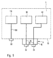
In Figur 5 kennzeichnet 1 einen als Autoradio ausgebildeten
Rundfunkempfänger mit einem Rundfunkempfangsteil 115, einem
Funktelefon 30 und einem Empfänger 40 zur
Positionsermittlung, der im vorliegenden Ausführungsbeispiel
als GPS-Empfänger (Global Positioning System) ausgebildet
ist. Weitere Baugruppen der Datenein- und -ausgabe des
Rundfunkempfängers 1 sind in für den Fachmann bekannter
Weise ausgeführt und in Figur 5 nicht dargestellt. An einer
Gehäuserückwand 10 des Rundfunkempfängers 1 ist eine erste
Antennenbuchse 60 für das Rundfunkempfangsteil 115
angeordnet und mit dem Rundfunkempfangsteil 115 über eine
erste Verbindungsleitung 120 verbunden. An der
Gehäuserückwand 10 des Rundfunkempfängers 1 ist außerdem ein
Antennenanschluß 5 angeordnet, der einen Anschlußkasten 15
mit einer zweiten Antennenbuchse 20 und einer dritten
Antennenbuchse 25 umfaßt. Die zweite Antennenbuchse 20 ist
dabei über eine zweite Verbindungsleitung 35 mit dem
Funktelefon 30 verbunden und die dritte Antennenbuchse 25
ist über eine dritte Verbindungsleitung 45 mit dem GPS-Empfänger
40 verbunden.In FIG. 5, 1 denotes a car radio
Radio receiver with a
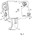
In Figur 1 ist der Anschlußkasten 15 dargestellt. Er besteht
aus einem Gehäuseteil 85 und einem Verschlußdeckel 90. Dabei
ist der Anschlußkasten 15 quaderförmig ausgebildet, wobei
der Verschlußdeckel 90 eine Längsseite des Anschlußkastens
15 abdeckt. Gemäß Figur 2 ist der Anschlußkasten 15 an
seinem Verschlußdeckel 90 über eine an der dem
Verschlußdeckel 90 gegenüberliegenden Seite des
Anschlußkastens 15 zugängliche Schraube 100 mit der
Gehäuserückwand 10 des Rundfunkempfängers 1 kraftschlüssig
verschraubt. Dabei sind auch andere kraftschlüssige
Verbindungsarten, wie beispielsweise Verkleben möglich. An
einer seiner Schmalseiten weist der Anschlußkasten 15 die
zweite Antennenbuchse 20 und die dritte Antennenbuchse 25
auf, die eine platzsparende Zuführung des jeweiligen
Antennenkabels parallel oder in kleinem Winkel zur
Gehäuserückwand 10 ermöglichen. Dies ist insbesondere bei
der Installation des Rundfunkempfängers 1 in einem
Einbauschacht eines Kraftfahrzeugs von Vorteil, der das
Volumen des Autoradios begrenzt. Der Anschlußkasten 15 weist
an einer weiteren Schmalseite eine äußere Haltevorrichtung
50 auf, die gemäß Figur 2 ein Antennenrohr 55 für
Rundfunkempfang in ebenfalls zur Gehäuserückwand 10
paralleler Führung bzw. kleinem Winkel hält. Das
Antennenrohr 55 ist dabei in Höhe der ersten Antennenbuchse
60 rechtwinklig abgewinkelt und mit der ersten
Antennenbuchse 60 an der Gehäuserückwand 10 des
Rundfunkempfängers 1 verbunden.In Figure 1, the
In Figur 3 ist eine Rückansicht des Anschlußkastens 15
dargestellt. Dabei ist im Verschlußdeckel 90 eine
Schraubenöffnung 110 zur Aufnahme der Schraube 100
dargestellt. Weiterhin ist am Verschlußdeckel 90 ein
Steckermodul 95 erkennbar, über das die zweite
Verbindungsleitung 35 mit einem Gegensteckkontakt der
Gehäuserückwand 10 des Rundfunkempfängers 1 verbunden ist.
Aus einer Öffnung 125 des Verschlußdeckels 90 ragt außerdem
die dritte Verbindungsleitung 45 heraus, die über eine
Öffnung der Gehäuserückwand 10 bis zum GPS-Empfänger 40
geführt ist.FIG. 3 is a rear view of the
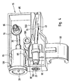
In Figur 4 ist das Innere des Anschlußkastens 15 bzw. des
Gehäuseteils 85 dargestellt. Dabei weist das Gehäuseteil 85
an der Schmalseite mit den beiden Antennenbuchsen 20, 25
einen ersten Antennenbuchsendurchbruch 130 und einen zweiten
Antennenbuchsendurchbruch 135 auf. Der erste
Antennenbuchsendurchbruch 130 dient dabei der Aufnahme der
zweiten Antennenbuchse 20 und der zweite
Antennenbuchsendurchbruch 135 dient der Aufnahme der dritten
Antennenbuchse 25. Eine zusätzliche Halterung erfährt die
zweite Antennenbuchse 20 dabei durch eine erste
Haltevorrichtung 65 im Innern des Gehäuseteils 85. Das durch
einen Durchbruch 140 des Verschlußdeckels 90 gemäß Figur 3
geführte Steckestmodul 95 ist gemäß Figur 4 über die zweite
Verbindungsleitung 35 mit der zweiten Antennenbuchse 20
verbunden und wird über eine zweite Haltevorrichtung 70 im
Gehäuseteil 85 stabilisiert. Die erste Haltevorrichtung 65
umgreift dabei die zylinderförmige zweite Antennenbuchse 20
durch einander gegenüberliegende und mit der dem
Verschlußdeckel 90 abgewandten Längsseite des Gehäuseteils
85 verbundenen entsprechend gebogenen Stegen. Die zweite
Haltevorrichtung 70 umschließt das Steckermodul 95
ringförmig und ist ebenfalls mit der dem Verschlußdeckel 90
gegenüberliegenden Längsseite des Gehäuseteils 85 verbunden.
Die dritte Verbindungsleitung 45 wird im Gehäuseteil 85
durch eine dritte Haltevorrichtung 75 in Form eines
Kabelkanals geführt. Die ebenfalls kreiszylinderförmig
ausgebildete dritte Antennenbuchse 25 wird durch eine vierte
Haltevorrichtung 80 im Gehäuseteil 85 in ihrer Lage fixiert.
Die vierte Haltevorrichtung 80 umschließt dabei die dritte
Antennenbuchse 25 ebenfalls mittels zweier einander
gegenüberliegender und mit der dem Verschlußdeckel 90
gegenüberliegenden Längsseite des Gehäuseteils 85
verbundenen Stegen. Im Gehäuseteil 85 ist weiterhin eine
zylinderförmige Schraubenführung 105 angeordnet, die zur
Aufnahme der Schraube 100 dient. Durch die vier
Haltevorrichtungen 65, 70, 75, 80 im Anschlußkasten 15 sind
also die zweite und die dritte Antennenbuchse 20, 25 und die
zweite und die dritte Verbindungsleitung 35, 45 in ihrer
Lage fixiert.In Figure 4, the interior of the
In einem weiteren Ausführungsbeispiel kann der
Anschlußkasten 15 auch an einer Gehäuseseitenwand des
Rundfunkempfängers 1 angeordnet sein.In a further embodiment, the
Das Gehäuseteil 85 und der Verschlußdeckel 90 sind
vorzugsweise aus Spritzguß hergestellt. Dabei kann das
Gehäuseteil 85 mit dem Verschlußdeckel 90 verklebt oder
verschweißt oder auf andere Weise verbunden sein. Eine
Verbindung des Gehäusteils 85 mit dem Verschlußdeckel 90 ist
auch dann gegeben, wenn beide Teile über die Schraube 100
kraftschlüssig mit der Gehäuserückwand 10 des
Rundfunkempfängers 1 verbunden sind.The
Zwischen die zweite und die dritte Antennenbuchse 20, 25 und
die zweite und die dritte Verbindungsleitung 35,45 ist im
ansonsten aus Kunststoff gebildeten Anschlußkasten 15 ein
Einlegeteil 200 aus Metall oder Bimetall zur
hochfrequenzmäßigen Abschirmung angeordnet. Mittels der vier
Haltevorrichtungen 65, 70, 75, 80 und der beiden
Antennenbuchsendurchbrüche 130, 135 sind die zweite und die
dritte Antennenbuchse 20, 25 und die zweite und die dritte
Verbindungsleitung 35, 45 so in den Anschlußkasten 15
eingesetzt, daß vor allem axiale Kräfte vom Anschlußkasten
15 aufgenommen werden und somit der Verschleiß der beiden
Antennenbuchsen 20, 25 und der beiden Verbindungsleitungen
35, 45 zumindest vermindert wird. Durch die vier
Haltevorrichtungen 65, 70, 75, 80 und die zwei
Antennenbuchsendurchbrüche 130, 135 werden die zweite und
die dritte Antennenbuchse 20, 25 und die zweite und die
dritte Verbindungsleitung 35, 45 auch in der Höhe gehalten
und so in ihrer Position fixiert.Between the second and the
Mit Hilfe des beschriebenen Anschlußkastens 15 ist eine
normierte Positionierung der zweiten und der dritten
Antennenbuchse 20, 25 möglich, so daß beispielsweise eine
Überprüfung der Funktion des Rundfunkempfängers 1 in der
Fertigung über eine einheitliche, mit den beiden
Antennenbuchsen 20, 25 des Anschlußkastens 15 zu verbindende
Adapterbaugruppe möglich ist.With the help of the described
Der Anschlußkasten 15 kann je nach Gerätetyp des
Rundfunkempfängers 1, das heißt in Abhängigkeit der Anzahl
der im Rundfunkempfänger 1 angeordneten Sende- und
Empfangsmodule, mit den notwendigen Antennenbuchsen bestückt
werden.The
Auch die erste Antennenbuchse 60 für das
Rundfunkempfangsteil 115 kann im Anschlußkasten 15
angeordnet sein.The
Claims (7)
Applications Claiming Priority (2)
| Application Number | Priority Date | Filing Date | Title |
|---|---|---|---|
| DE19706709 | 1997-02-20 | ||
| DE1997106709 DE19706709C2 (en) | 1997-02-20 | 1997-02-20 | Radio receiver |
Publications (3)
| Publication Number | Publication Date |
|---|---|
| EP0860892A2 true EP0860892A2 (en) | 1998-08-26 |
| EP0860892A3 EP0860892A3 (en) | 2000-07-19 |
| EP0860892B1 EP0860892B1 (en) | 2006-03-29 |
Family
ID=7820932
Family Applications (1)
| Application Number | Title | Priority Date | Filing Date |
|---|---|---|---|
| EP19980101133 Expired - Lifetime EP0860892B1 (en) | 1997-02-20 | 1998-01-23 | Radio receiver with a stabilisation of the antenna connector |
Country Status (2)
| Country | Link |
|---|---|
| EP (1) | EP0860892B1 (en) |
| DE (2) | DE19706709C2 (en) |
Families Citing this family (1)
| Publication number | Priority date | Publication date | Assignee | Title |
|---|---|---|---|---|
| DE10352169A1 (en) | 2003-11-05 | 2005-06-09 | Siemens Ag | Adapter for car radios |
Citations (5)
| Publication number | Priority date | Publication date | Assignee | Title |
|---|---|---|---|---|
| US4881910A (en) * | 1987-09-21 | 1989-11-21 | Walter Odemer Co., Inc. | Quick release minimum profile shuttle for vehicle radios and tape players |
| EP0483956A2 (en) * | 1990-10-30 | 1992-05-06 | Nokia Mobile Phones (U.K.) Limited | Combined broadcast radio receiver and radio telephone |
| DE4110897A1 (en) * | 1991-02-27 | 1992-09-03 | Siria Srl | Connection system for car radio aerial |
| US5190461A (en) * | 1991-06-17 | 1993-03-02 | Fujitsu Limited | Connector assembly with both functions of coaxial connector and multiple contact connector |
| DE19644648C1 (en) * | 1996-10-26 | 1998-05-20 | Bosch Gmbh Robert | Radio receiver |
-
1997
- 1997-02-20 DE DE1997106709 patent/DE19706709C2/en not_active Expired - Fee Related
-
1998
- 1998-01-23 DE DE59813464T patent/DE59813464D1/en not_active Expired - Lifetime
- 1998-01-23 EP EP19980101133 patent/EP0860892B1/en not_active Expired - Lifetime
Patent Citations (5)
| Publication number | Priority date | Publication date | Assignee | Title |
|---|---|---|---|---|
| US4881910A (en) * | 1987-09-21 | 1989-11-21 | Walter Odemer Co., Inc. | Quick release minimum profile shuttle for vehicle radios and tape players |
| EP0483956A2 (en) * | 1990-10-30 | 1992-05-06 | Nokia Mobile Phones (U.K.) Limited | Combined broadcast radio receiver and radio telephone |
| DE4110897A1 (en) * | 1991-02-27 | 1992-09-03 | Siria Srl | Connection system for car radio aerial |
| US5190461A (en) * | 1991-06-17 | 1993-03-02 | Fujitsu Limited | Connector assembly with both functions of coaxial connector and multiple contact connector |
| DE19644648C1 (en) * | 1996-10-26 | 1998-05-20 | Bosch Gmbh Robert | Radio receiver |
Also Published As
| Publication number | Publication date |
|---|---|
| EP0860892A3 (en) | 2000-07-19 |
| EP0860892B1 (en) | 2006-03-29 |
| DE19706709A1 (en) | 1998-09-03 |
| DE59813464D1 (en) | 2006-05-18 |
| DE19706709C2 (en) | 2003-12-18 |
Similar Documents
| Publication | Publication Date | Title |
|---|---|---|
| EP1851567B1 (en) | Modular ultrasonic sensor | |
| DE60205562T2 (en) | Directionless squib connector for automotive airbag systems | |
| EP3383709B1 (en) | Cable conduit device for connection cables of an airbag module, wiring system, airbag module, and steering wheel or vehicle comprising a cable conduit device of said type | |
| DE10393763B4 (en) | Connector assembly with a dielectric cover | |
| DE102018205919A1 (en) | Electrical connection box and wiring harness | |
| EP2816372A2 (en) | Distance sensor for a motor vehicle, and assembly of a plurality of distance sensors | |
| DE102011081016A1 (en) | Sensor module and method for producing a sensor module | |
| DE102016223642A1 (en) | Engaging structure, electronic component module and electrical connection box | |
| WO2007131826A1 (en) | Mounting system and mounting procedure for a vehicle antenna | |
| DE202008004580U1 (en) | Device for receiving a mobile terminal | |
| DE102011078284A1 (en) | Connectors, in particular electrical connectors | |
| DE102010049297A1 (en) | Optical connector | |
| DE10084595B4 (en) | Electrical connection box | |
| DE19729854C2 (en) | Device for connecting an external antenna | |
| EP0860892B1 (en) | Radio receiver with a stabilisation of the antenna connector | |
| DE112017004830T5 (en) | coaxial connector | |
| EP0932522B1 (en) | Radio receiver | |
| DE102015016467A1 (en) | Motor vehicle door handle with integrated electronic module | |
| DE102018126448A1 (en) | Electrical connector and electrical connector | |
| DE102020124092B4 (en) | Connector arrangement for connecting an electrical line to an electrical component | |
| EP3465818B1 (en) | Communication device for a diagnostic system of a motor vehicle | |
| EP2991165B1 (en) | Electrical connector, connector element and use | |
| DE19647925C1 (en) | Cable connector for electrical ribbon cable used in motor vehicle steering wheel | |
| DE102016219421A1 (en) | Housing with strain relief for a cable | |
| DE60131119T2 (en) | Optical hybrid connector for an optical network |
Legal Events
| Date | Code | Title | Description |
|---|---|---|---|
| PUAI | Public reference made under article 153(3) epc to a published international application that has entered the european phase |
Free format text: ORIGINAL CODE: 0009012 |
|
| AK | Designated contracting states |
Kind code of ref document: A2 Designated state(s): DE FR IT |
|
| PUAL | Search report despatched |
Free format text: ORIGINAL CODE: 0009013 |
|
| AK | Designated contracting states |
Kind code of ref document: A3 Designated state(s): AT BE CH DE DK ES FI FR GB GR IE IT LI LU MC NL PT SE |
|
| RIC1 | Information provided on ipc code assigned before grant |
Free format text: 7H 01Q 1/12 A, 7H 01Q 21/30 B |
|
| 17P | Request for examination filed |
Effective date: 20010119 |
|
| AKX | Designation fees paid |
Free format text: DE FR IT |
|
| 17Q | First examination report despatched |
Effective date: 20030827 |
|
| GRAP | Despatch of communication of intention to grant a patent |
Free format text: ORIGINAL CODE: EPIDOSNIGR1 |
|
| GRAS | Grant fee paid |
Free format text: ORIGINAL CODE: EPIDOSNIGR3 |
|
| GRAA | (expected) grant |
Free format text: ORIGINAL CODE: 0009210 |
|
| AK | Designated contracting states |
Kind code of ref document: B1 Designated state(s): DE FR IT |
|
| PG25 | Lapsed in a contracting state [announced via postgrant information from national office to epo] |
Ref country code: IT Free format text: LAPSE BECAUSE OF FAILURE TO SUBMIT A TRANSLATION OF THE DESCRIPTION OR TO PAY THE FEE WITHIN THE PRE;WARNING: LAPSES OF ITALIAN PATENTS WITH EFFECTIVE DATE BEFORE 2007 MAY HAVE OCCURRED AT ANY TIME BEFORE 2007. THE CORRECT EFFECTIVE DATE MAY BE DIFFERENT FROM THE ONE RECORDED.SCRIBED TIME-LIMIT Effective date: 20060329 |
|
| REF | Corresponds to: |
Ref document number: 59813464 Country of ref document: DE Date of ref document: 20060518 Kind code of ref document: P |
|
| ET | Fr: translation filed | ||
| PLBE | No opposition filed within time limit |
Free format text: ORIGINAL CODE: 0009261 |
|
| STAA | Information on the status of an ep patent application or granted ep patent |
Free format text: STATUS: NO OPPOSITION FILED WITHIN TIME LIMIT |
|
| 26N | No opposition filed |
Effective date: 20070102 |
|
| PGFP | Annual fee paid to national office [announced via postgrant information from national office to epo] |
Ref country code: IT Payment date: 20110129 Year of fee payment: 14 |
|
| PG25 | Lapsed in a contracting state [announced via postgrant information from national office to epo] |
Ref country code: IT Free format text: LAPSE BECAUSE OF NON-PAYMENT OF DUE FEES Effective date: 20120123 |
|
| PGFP | Annual fee paid to national office [announced via postgrant information from national office to epo] |
Ref country code: FR Payment date: 20130207 Year of fee payment: 16 |
|
| REG | Reference to a national code |
Ref country code: FR Ref legal event code: ST Effective date: 20140930 |
|
| PG25 | Lapsed in a contracting state [announced via postgrant information from national office to epo] |
Ref country code: FR Free format text: LAPSE BECAUSE OF NON-PAYMENT OF DUE FEES Effective date: 20140131 |
|
| PGFP | Annual fee paid to national office [announced via postgrant information from national office to epo] |
Ref country code: DE Payment date: 20160322 Year of fee payment: 19 |
|
| REG | Reference to a national code |
Ref country code: DE Ref legal event code: R119 Ref document number: 59813464 Country of ref document: DE |
|
| PG25 | Lapsed in a contracting state [announced via postgrant information from national office to epo] |
Ref country code: DE Free format text: LAPSE BECAUSE OF NON-PAYMENT OF DUE FEES Effective date: 20170801 |