EP0860180A2 - Device for delivering localized X-ray radiation to an interior of a body and method of manufacture - Google Patents
Device for delivering localized X-ray radiation to an interior of a body and method of manufacture Download PDFInfo
- Publication number
- EP0860180A2 EP0860180A2 EP98102901A EP98102901A EP0860180A2 EP 0860180 A2 EP0860180 A2 EP 0860180A2 EP 98102901 A EP98102901 A EP 98102901A EP 98102901 A EP98102901 A EP 98102901A EP 0860180 A2 EP0860180 A2 EP 0860180A2
- Authority
- EP
- European Patent Office
- Prior art keywords
- getter
- diamond film
- cathode
- vacuum housing
- disposed
- Prior art date
- Legal status (The legal status is an assumption and is not a legal conclusion. Google has not performed a legal analysis and makes no representation as to the accuracy of the status listed.)
- Granted
Links
Images


Classifications
-
- A—HUMAN NECESSITIES
- A61—MEDICAL OR VETERINARY SCIENCE; HYGIENE
- A61N—ELECTROTHERAPY; MAGNETOTHERAPY; RADIATION THERAPY; ULTRASOUND THERAPY
- A61N5/00—Radiation therapy
- A61N5/10—X-ray therapy; Gamma-ray therapy; Particle-irradiation therapy
- A61N5/1001—X-ray therapy; Gamma-ray therapy; Particle-irradiation therapy using radiation sources introduced into or applied onto the body; brachytherapy
-
- H—ELECTRICITY
- H01—ELECTRIC ELEMENTS
- H01J—ELECTRIC DISCHARGE TUBES OR DISCHARGE LAMPS
- H01J35/00—X-ray tubes
- H01J35/32—Tubes wherein the X-rays are produced at or near the end of the tube or a part thereof which tube or part has a small cross-section to facilitate introduction into a small hole or cavity
-
- A—HUMAN NECESSITIES
- A61—MEDICAL OR VETERINARY SCIENCE; HYGIENE
- A61N—ELECTROTHERAPY; MAGNETOTHERAPY; RADIATION THERAPY; ULTRASOUND THERAPY
- A61N5/00—Radiation therapy
- A61N5/10—X-ray therapy; Gamma-ray therapy; Particle-irradiation therapy
- A61N5/1001—X-ray therapy; Gamma-ray therapy; Particle-irradiation therapy using radiation sources introduced into or applied onto the body; brachytherapy
- A61N5/1002—Intraluminal radiation therapy
-
- H—ELECTRICITY
- H01—ELECTRIC ELEMENTS
- H01J—ELECTRIC DISCHARGE TUBES OR DISCHARGE LAMPS
- H01J2235/00—X-ray tubes
- H01J2235/20—Arrangements for controlling gases within the X-ray tube
- H01J2235/205—Gettering
Definitions
- the present invention is directed to a catheter device and method of fabrication, and more particularly to a catheter device and method for fabrication for delivering localized radiation to vessels, lumens, or cavities of a body, such as cardiovascular tissue, to treat restenosis and other conditions.
- Cardiovascular diseases affect millions of people, often causing heart attacks and death.
- One common aspect of many cardiovascular diseases is stenosis, or the thickening of the artery or vein, decreasing blood flow through the vessel.
- Angioplasty procedures have been developed to reopen clogged arteries without resorting to a bypass operation.
- arteries become occluded again after an angioplasty procedure.
- This recurrent thickening of the vessel is termed restenosis. Restenosis frequently requires a second angioplasty and eventual bypass surgery. Bypass surgery is very stressful on the patient, requiring the chest to be opened, and presents risks from infection, anesthesia, and heart failure.
- Effective methods of preventing or treating restenosis could benefit millions of people.
- One approach uses drug therapy to prevent or minimize restenosis.
- Heparin has been used as an anticoagulant and an inhibitor of arterial smooth muscle proliferation.
- Dexamethasone is another drug which may prevent smooth muscle proliferation. It has been suggested that such anticoagulants and antiproliferative agents may be effective at preventing restenosis after an angioplasty procedure thereby eliminating the necessity to repeat the procedure.
- a drug delivery device that is adapted to traverse the human cardiovascular or circulatory system must be used. Such a device must be capable of entering small blood vessels with diameters of about two to four millimeters. Such a device must also be capable of making hairpin turns at it follows a tortuous path.
- catheters have therefore been developed to deliver these and other effective drugs to the site of the restenosis. These catheters frequently use pressure to drive the drug into the tissue or plaque, potentially causing damage to the lumen wall. Techniques of delivery which do not use pressure use occlusion balloons to isolate the area from blood flow to enable sufficient absorption of the medication. However, the blood flow in an artery can only be occluded for a limited period of time while the drug is delivered. Due to these and other problems, localized delivery of drugs has not provided adequate treatment to prevent or reduce restenosis.
- Another treatment for restenosis that has been attempted is beta-irradiation of the vessel wall by positioning radioactive isotopes in the vessel at the site of the restenosis.
- the depth of the penetration of the radiation is impossible to control with this method.
- the depth of the radiation is determined by the type of the radio-isotope used.
- the radioactive source will also irradiate other healthy parts of the body as it is brought to the site to be treated.
- Another disadvantage is that medical personnel must take extensive precautions when handling the radioactive material.
- the present invention provides a device for insertion into a body of a subject being treated to deliver localized x-ray radiation, and a method for fabricating such a device.
- the device includes a cathode structure that has a thin diamond film disposed within a vacuum housing.
- the device further comprises an anode disposed within the vacuum housing, the diamond film being operative with the anode to produce localized x-ray radiation.
- a method for fabricating a device for localized x-ray radiation which includes the formation of a thin diamond film on a shaped getter.
- the method further includes the steps of providing a getter with a shaped surface, where the getter has an activation temperature, and forming a thin diamond film cathode on the getter at temperatures below the activation temperature.
- the method further comprises disposing the cathode in a vacuum housing an increasing the temperature to the activation temperature of the getter.
- the present invention is applicable to a variety of devices, methods of fabrication, methods of use, systems and arrangements which irradiate lumens, vessels, or interior sites in a body with x-ray radiation.
- the invention is particularly advantageous in preventing restenosis in the cardiovascular system. While the present invention is not so limited, an appreciation of various aspects of the invention is best gained through a discussion of application examples operating in such an environment.
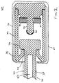
- Fig. 1 illustrates a first embodiment in which a cathode of an x-ray device 20 comprises a thin diamond film 28 which may be used to deliver localized x-ray radiation to treat, for example, restenosis.
- a cathode of an x-ray device 20 comprises a thin diamond film 28 which may be used to deliver localized x-ray radiation to treat, for example, restenosis.
- keV kiloelectronvolts
- the ability to lower the required electric field at the cathode results in a less expensive manufacturing technique.
- Small irregularities on the surface of the cathode result in an increase in the magnitude of the electrical field for an applied voltage, thereby increasing the chance of electrical flashover.
- the weaker the required electrical field at the cathode the more imperfections can be tolerated on the cathode surface without risking flashover.
- x-ray radiation is produced, while keeping the required electrical field low, by using a diamond film as a cathode.
- Diamond coatings display attractive properties as field emitters, losing electrons easily as a field is applied.
- the electrical field required to produce about 8-10 keV of radiation is about 20 keV/micron.
- the required electrical field to produce a similar level of radiation from a metal emitter is well over 1,000 keV/micron.
- a diamond-coated cathode is used to achieve x-ray treatment radiation while producing significantly weaker electrical fields at the cathode.
- the x-ray device 20 comprises a flexible catheter shaft 22 adapted for insertion into blood vessels, lumens, or other body cavities. While in this particular embodiment a catheter shaft is shown, generally, many different elements could be used to guide the x-ray device of the present invention to a treatment site.
- the shaft 22 has a proximal and distal portion, the distal portion being shown in Fig. 1.
- the device may be inserted in the body at the femoral artery and threaded through a network of blood vessels to reach the heart.
- the shaft must be extremely flexible and have a maximum diameter less than or equal to about 3 millimeters. In other applications, the properties of the shaft must meet the requirements of the task.
- a vacuum housing 23 which encloses the x-ray source components.
- the x-ray source components include an anode 24, a cathode base 26, a thin diamond film 28 located on the cathode base 26, and a getter 30.
- the outer diameter of the integrated x-ray device shown in Fig. 1 is less than or equal to approximately 2.5 millimeters.
- a coaxial cable 38 may be disposed within the shaft 22.
- the coaxial cable 38 is coupled to a high voltage generator, not shown, at the proximal end of the shaft 22.
- An internal conductor 40 of the coaxial cable 38 is coupled to the anode 24 at the appropriate voltage.
- An external conductive layer 42 of the coaxial cable 38 is held at ground and coupled to the cathode base 26 via a conductive solder 44.
- Other known methods may also be used to apply the electric field across the anode and cathode.
- a coronary artery after dilatation by angioplasty typically has a diameter of only about 3.0 millimeters. Therefore, a coaxial cable and any covering used in this device must have a diameter of less than or equal to 3.0 millimeter. The cable must also be able to carry the required voltages and have sufficient flexibility to make numerous sharp turns as it follows the artery path. Standard high voltage coaxial cables are generally not flexible enough. However, the inventors have found that miniature high frequency coaxial cables with an outer diameter of approximately 1.0 millimeter to 3.0 millimeters are available which also exhibit sufficient flexibility. These types of cables are typically used in high frequency applications at voltages less than several kilovolts (KV).
- KV kilovolts
- a cable with an outer diameter less than or equal to 3.0 millimeters is used.
- the cable has an outer diameter of 1-2 millimeters.
- Such cables are manufactured by, for example, New England Electric Wire Corporation, Lisborn, New Hampshire.
- a heavy metal material can be used for the anode 24, such as tungsten or gold.
- the material used for the cathode base 26 depends on how the diamond film is formed.
- the thin diamond film 28 can be obtained by chemical vapor deposition, as is known in the art.
- Various materials may serve as an effective substrate for diamond film synthesis by chemical vapor deposition, such as tungsten, molybdenum, and tantalum.
- the diamond film could also be fabricated by other methods, such as by laser ion deposition, making a wider range of materials available for the base of the cathode.
- diamond film contemplates a coating of carbon having diamond-like bonds which demonstrate negative electron affinity. It is also desirable to have sufficient conductivity to create a constant supply of electrons to the surface of the cathode. The presence of some graphite bonds in the diamond films will contribute to conductivity. Thus a combination of a diamond film having both sp3 carbon bonds, to function as a cathode, and some sp2 carbon bonds, to facilitate conductivity, is particularly suited for use in such a system. Other elements may also be present in the film in small quantities. According to the invention, the diamond film will have the property that it can emit electrons at electrical fields greater than or equal to about 20 KV/micron. This required electric field is significantly lower when compared to that required for metal emitters such as molybdenum or silicon, which require greater than 1,000 KV/micron.
- a getter 30 is disposed within the vacuum housing 23 in order to aid in creating and maintaining a vacuum condition of high quality.
- the getter 30 has an activation temperature, at which it will react with stray gas molecules in the vacuum. After the getter 30 is disposed within the vacuum housing and the housing pumped out, the device is heated to the activation temperature. It is desirable that the getter used have an activation temperature that is not so high that the x-ray device will be damaged when heated to the activation temperature.
- a SAES ST 101 alloy getter could be used, which has an activation temperature in the range 750 to 900°C and is composed of approximately 64% zirconium and 16% aluminum.
- a ST 707 alloy getter could also be used, which has an activation temperature in the range 400-500°C and is composed of approximately 70% zirconium, 24.6% vanadium, and 5.4% iron.
- a wall of the vacuum chamber 36 should be transparent to x-rays in order to allow the full dosage to reach the lumen wall.
- the wall 36 can comprise boron nitride, or another metal or ceramic material which is transparent to x-rays.
- Other possibilities include pyrolytic boron nitride, isotropic boron nitride, anisotropic boron nitride, beryllium, beryllium oxide, aluminum, aluminum oxide, or graphite.
- an electrical field ex ists at the surface of the cathode 26 and current flows from the cathode 26 to the anode 24, while just on the outside of the vacuum housing a conductive braid or solder 44 is held at ground.
- these two potentials must be insulated from each other or electrical flashover will occur.
- a vacuum wall of pyrolytic boron nitride can provide some insulation. If a metal is used as the vacuum chamber wall 36, an insulative layer is necessary.
- an electrically insulating material 50 can be placed at the joints of the vacuum chamber wall.
- the vacuum chamber further includes a biocompatible coating 46, such as polyethylene, polyurethane or Teflon® material.
- the joints 34 between the vacuum chamber wall 36 and the anode 24 can be vacuum furnace brazed.
- the x-ray device When used to radiate the wall of a lumen, according to one embodiment of the invention, the x-ray device is placed within a catheter.
- the catheter is introduced into the lumen to be treated through the skin.
- the x-ray device is then guided through the lumen, using techniques known in the art, until it is positioned near the area to be radiated.
- the high voltage generator is activated and an electrical field is established across the cathode 28 and the anode 24.
- the thin diamond coating 28 loses electrons which are accelerated toward the anode 24.
- electromagnetic radiation is emitted by the material of the anode 24.
- x-ray radiation is produced by the Bremsstrahlung effect.
- the x-ray catheter device can be used to effectively prevent restenosis.
- the voltage source is discontinued and the catheter withdrawn from the body.
- the dosage of x-ray radiation to be applied to the interior of a body will generally be within the scope of the attending physicians judgment, and will be based on individual conditions, such as the severity of the condition at the site to be treated and the particular patient.
- irradiation in the range of 10 to 50 Grays may be applied to an area of the interior of the esophagus to treat Barrett's esophagus or prevent restenosis of the esophagus.
- x-ray radiation in the range of 15 to 30 Grays may be applied to the esophagus.
- irradiation by about 10 to 50 grays could be used to prevent restenosis after dilation. Irradiation by about 20 grays is believed to be effective in limiting restenosis.
- the treatment will be structured to last about 2 to 10 minutes, or, more preferably, 3 to 5 minutes.
- the x-ray emitter may be repositioned during the course of radiation treatment, depending on the length of the area requiring treatment.
- a certain amount of heat is generally generated by the x-ray unit at the anode. Thus, some mechanism for cooling the structure may be required.
- the typical blood flow to an artery is about 50-60 cm 3 /minute, which aids in dissipating heat conducted through the vacuum housing.
- additional cooling methods may be required.
- Fig. 2 another embodiment of the x-ray device of the present invention is illustrated.
- a thin diamond film is placed directly on a getter.
- the getter into the cathode structure, significant size advantages can be obtained.
- Laser ion source deposition may be used to place the diamond film directly upon a getter.
- a traditional chemical vapor deposition process takes place at approximately 900°C. Therefore, a getter used as a substrate in such a process would be activated and used up during the deposition process.
- the use of a laser ion source deposition process which can be carried out at room temperature, allows a diamond film to be created on a getter without activating the getter.
- a laser ion source deposition process is described in U.S. Patent No. 4,987,007, Wagal et al. U.S. Patent No. 4,987,007.
- a graphite target and the substrate to be coated are disposed in a vacuum chamber.
- the graphite target is radiated with a focused laser beam from a pulse laser.
- the laser beam ejects a plume of carbon vapor from the graphite target. A portion of the atoms in the plume are ionized by the focused laser beam, and the positive carbon ions are accelerated towards the substrate by the accelerating grid.
- the outer diameter of the integrated x-ray device of the embodiment illustrated in Fig. 2 will be less than or equal to approximately one and one quarter millimeters.
- Fig. 1 The outer vacuum housing features of Fig. 1 may also be used in the embodiment shown in Fig. 2, although these features are not illustrated in Fig. 2.
- the outer biocompatible layer, vacuum furnace brazed joints and insulating material may be used in the embodiment of Fig. 2.
- a conductive solder material 52 provides an electrical connection between the external conductive layer 42 of the coaxial cable and the cathode base 48.
- the getter 56 will be conductive enough to provide the electrical connection between the thin diamond film 28 and the conductive solder 52.
- the ST 707 alloy getter could also be used, which has an activation temperature in the range 400-500°C and is composed of approximately 70% zirconium, 24.6% vanadium, and 5.4% iron.
- Fig. 3 shows a method for creating the x-ray device of the second embodiment.
- the getter is machined into a desirable shape for the cathode in step 70.
- a cone shape or rounded cone shape, for example, may be used for the shape of the cathode.
- a thin diamond film is formed on a tip portion of the getter in step 72.
- the tip portion of the getter corresponds to a cathode structure.
- the diamond film formation is carried out at a temperature below the activation temperature of the getter using, for example, laser ion source deposition techniques.
- Two subassemblies are constructed. In step 74, one subassembly comprises the cathode structure and an end cap 59.
- the other subassembly of step 76 comprises the anode 24 and the vacuum chamber walls 36. These two subassemblies are sealed in a high vacuum furnace and heated to approximately 400-500°C to bake out gas molecules from the materials for about two hours in step 78. The subassemblies are sealed together in step 80, while still at high vacuum furnace conditions. The temperature is increased to approximately 500-700°C for step 82 high vacuum furnace brazing of the joints of the x-ray device. The device is maintained at a high temperature for several hours to thoroughly activate the getter in step 84. The device is cooled in step 86, tested, and cables are attached.
- the getter is a miniature vacuum pump disposed within the vacuum housing. This method permits the manufacture of an x-ray device having an outer diameter of less than or equal to approximately one and one-quarter millimeter.
Abstract
Description
Claims (11)
- A device for insertion into a body of a subject being treated, the device delivering localized x-ray radiation, comprising:a shaft, including a proximal and a distal portion;a vacuum housing coupled to the distal portion of the shaft;an anode disposed within the vacuum housing; anda cathode structure disposed within the vacuum housing, the cathode structure including a thin diamond film, the thin diamond film being operative with the anode to produce the localized x-ray radiation.
- The device of claim 1, wherein the cathode structure includes a base on which the thin diamond film is disposed, the base comprising material selected from the group consisting of molybdenum, tungsten and tantalum.
- The device of claim 1, wherein an outer diameter of the integrated device is less than or equal to approximately two and one-half millimeter.
- The device of claim 1, wherein an outer diameter of the integrated device is less than or equal to one and one-quarter millimeter.
- A device of claim 1, wherein the vacuum housing comprises material selected from the group consisting of boron nitride, isotropic boron nitride, anisotropic boron nitride and pyrolytic boron nitride.
- The device of claim 1 further comprising a getter disposed within the vacuum housing.
- The device of claim 1 wherein the cathode structure further comprises a getter on which the thin diamond film is disposed.
- The device of claim 6 or 7 wherein the getter is comprised of material selected from zirconium, vanadium, aluminium, iron and combinations thereof.
- The device of claim 1, wherein the shaft includes a catheter and the vacuum housing is disposed within the catheter.
- The device of claim 1, further comprising a flexible coaxial cable in the shaft, the coaxial cable having an outer diameter of three millimeters or less, wherein the cable is capable of conducting a voltage greater than or equal to 10 kilovolts without electrical discharge.
- A method for fabricating a device for producing localized x-ray radiation, the device being capable of insertion into a body of a subject being treated, the method comprising the steps of:providing a getter having a tip portion corresponding to a cathode structure where the getter has an activation temperature;forming a thin diamond film on the tip portion of the getter at a temperature less than the activation temperature to provide a thin diamond film cathode;disposing the cathode within a vacuum housing; andincreasing the temperature to the activation temperature to activate the getter.
Applications Claiming Priority (2)
| Application Number | Priority Date | Filing Date | Title |
|---|---|---|---|
| US806244 | 1997-02-21 | ||
| US08/806,244 US6377846B1 (en) | 1997-02-21 | 1997-02-21 | Device for delivering localized x-ray radiation and method of manufacture |
Publications (3)
| Publication Number | Publication Date |
|---|---|
| EP0860180A2 true EP0860180A2 (en) | 1998-08-26 |
| EP0860180A3 EP0860180A3 (en) | 1999-04-07 |
| EP0860180B1 EP0860180B1 (en) | 2003-09-24 |
Family
ID=25193633
Family Applications (1)
| Application Number | Title | Priority Date | Filing Date |
|---|---|---|---|
| EP98102901A Expired - Lifetime EP0860180B1 (en) | 1997-02-21 | 1998-02-19 | Device for delivering localized X-ray radiation to an interior of a body and method of manufacture |
Country Status (4)
| Country | Link |
|---|---|
| US (1) | US6377846B1 (en) |
| EP (1) | EP0860180B1 (en) |
| DE (1) | DE69818322T2 (en) |
| DK (1) | DK0860180T3 (en) |
Cited By (16)
| Publication number | Priority date | Publication date | Assignee | Title |
|---|---|---|---|---|
| WO1999005694A1 (en) * | 1997-07-25 | 1999-02-04 | Xrt Corp. | Miniature x-ray device having cold cathode |
| WO1999009580A1 (en) * | 1997-08-18 | 1999-02-25 | Xrt Corp. | Cathode from getter material |
| WO2000010643A1 (en) * | 1998-08-21 | 2000-03-02 | Xrt Corp. | Cathode structure with getter material and diamond film, and methods of manufacture thereof |
| US6289079B1 (en) | 1999-03-23 | 2001-09-11 | Medtronic Ave, Inc. | X-ray device and deposition process for manufacture |
| US6320935B1 (en) | 2000-02-28 | 2001-11-20 | X-Technologies, Ltd. | Dosimeter for a miniature energy transducer for emitting X-ray radiation |
| US6324257B1 (en) | 1998-06-04 | 2001-11-27 | X-Technologies Inc. | Radiotherapeutical device and use thereof |
| WO2002007183A1 (en) * | 2000-07-19 | 2002-01-24 | Saes Getters S.P.A. | Process for manufacturing assemblies comprising a base and a device integrating the functions of cathode and getter for miniaturized x-ray emitters and assemblies so produced |
| US6353658B1 (en) | 1999-09-08 | 2002-03-05 | The Regents Of The University Of California | Miniature x-ray source |
| US6390967B1 (en) | 2000-09-14 | 2002-05-21 | Xoft Microtube, Inc. | Radiation for inhibiting hyperplasia after intravascular intervention |
| WO2002056952A2 (en) * | 2001-01-17 | 2002-07-25 | Medtronic Ave, Inc. | Miniature x-ray device and method of its manufacture |
| US6463124B1 (en) | 1998-06-04 | 2002-10-08 | X-Technologies, Ltd. | Miniature energy transducer for emitting x-ray radiation including schottky cathode |
| US6464625B2 (en) | 1999-06-23 | 2002-10-15 | Robert A. Ganz | Therapeutic method and apparatus for debilitating or killing microorganisms within the body |
| US6537195B2 (en) | 2001-05-07 | 2003-03-25 | Xoft, Microtube, Inc. | Combination x-ray radiation and drug delivery devices and methods for inhibiting hyperplasia |
| EP1494260A1 (en) * | 2003-06-30 | 2005-01-05 | Nucletron B.V. | Miniature X-ray source device |
| EP1520603A1 (en) * | 2003-10-03 | 2005-04-06 | Nucletron B.V. | Solid state brachytherapy applicator |
| US7018371B2 (en) | 2001-05-07 | 2006-03-28 | Xoft, Inc. | Combination ionizing radiation and radiosensitizer delivery devices and methods for inhibiting hyperplasia |
Families Citing this family (15)
| Publication number | Priority date | Publication date | Assignee | Title |
|---|---|---|---|---|
| US6377846B1 (en) | 1997-02-21 | 2002-04-23 | Medtronic Ave, Inc. | Device for delivering localized x-ray radiation and method of manufacture |
| EP1205216A3 (en) * | 2000-11-09 | 2004-01-02 | Radi Medical Technologies AB | Miniature x-ray source insulation structure |
| DE60100027T2 (en) * | 2001-02-09 | 2003-04-30 | Radi Medical Technologies Ab U | Medical system with a miniaturized x-ray tube |
| US6875165B2 (en) * | 2001-02-22 | 2005-04-05 | Retinalabs, Inc. | Method of radiation delivery to the eye |
| US6953425B2 (en) * | 2003-04-25 | 2005-10-11 | Medtronic Vascular, Inc. | Method of treating vulnerable plaque using a catheter-based radiation system |
| EP1720608B1 (en) * | 2004-02-12 | 2010-11-17 | NeoVista, Inc. | Apparatus for intraocular brachytherapy |
| US7563222B2 (en) * | 2004-02-12 | 2009-07-21 | Neovista, Inc. | Methods and apparatus for intraocular brachytherapy |
| US7200203B2 (en) * | 2004-04-06 | 2007-04-03 | Duke University | Devices and methods for targeting interior cancers with ionizing radiation |
| CA2629648A1 (en) * | 2005-11-15 | 2007-05-24 | Neovista Inc. | Methods and apparatus for intraocular brachytherapy |
| US9220837B2 (en) | 2007-03-19 | 2015-12-29 | Insuline Medical Ltd. | Method and device for drug delivery |
| US8622991B2 (en) * | 2007-03-19 | 2014-01-07 | Insuline Medical Ltd. | Method and device for drug delivery |
| CN104069567A (en) | 2007-03-19 | 2014-10-01 | 茵苏莱恩医药有限公司 | Drug delivery device |
| EP2231229A1 (en) | 2007-12-18 | 2010-09-29 | Insuline Medical Ltd. | Drug delivery device with sensor for closed-loop operation |
| EP2296756A1 (en) | 2008-06-04 | 2011-03-23 | Neovista, Inc. | Handheld radiation delivery system for advancing a radiation source wire |
| MX2011004817A (en) | 2008-11-07 | 2011-07-28 | Insuline Medical Ltd | Device and method for drug delivery. |
Citations (1)
| Publication number | Priority date | Publication date | Assignee | Title |
|---|---|---|---|---|
| US4987007A (en) | 1988-04-18 | 1991-01-22 | Board Of Regents, The University Of Texas System | Method and apparatus for producing a layer of material from a laser ion source |
Family Cites Families (119)
| Publication number | Priority date | Publication date | Assignee | Title |
|---|---|---|---|---|
| US3125679A (en) | 1964-03-17 | Ryohei | ||
| GB230183A (en) | 1923-12-06 | 1925-03-06 | Ruben Samuel | Improvements in or relating to x-ray tubes |
| US1881448A (en) | 1928-08-15 | 1932-10-11 | Formell Corp Ltd | X-ray method and means |
| US1786373A (en) | 1929-11-30 | 1930-12-23 | Ralph C Walker | Electrically-heated therapeutical appliance |
| US2173258A (en) | 1937-11-27 | 1939-09-19 | Rca Corp | Active metal compound for vacuum tubes |
| US2467812A (en) | 1947-04-01 | 1949-04-19 | Gen Electric | Noncontacting thickness gauge |
| US2766385A (en) | 1952-09-11 | 1956-10-09 | Herrnring Gunther | Optical image-forming plural reflecting mirror systems |
| US3005096A (en) | 1958-05-14 | 1961-10-17 | Bell Telephone Labor Inc | Irradiation of monoclinic glycine sulphate |
| US3073960A (en) | 1958-07-14 | 1963-01-15 | Westinghouse Electric Corp | Teletherapy device |
| US3388314A (en) | 1959-04-06 | 1968-06-11 | Control Data Corp | Apparatus for generating radiation of frequencies higher than those of light |
| NL129734C (en) | 1960-07-22 | |||
| US3256439A (en) | 1962-12-17 | 1966-06-14 | Field Emission Corp | High voltage and high current pulse generator in combination with field emission type x-ray tube |
| AT273311B (en) | 1963-07-09 | 1969-08-11 | Oesterr Studien Atomenergie | Device for screening and for making parts of the human body immediately visible, in particular the oral cavity |
| US3348051A (en) | 1965-11-22 | 1967-10-17 | Automation Ind Inc | Power supply for an X-ray tube having a frequency responsive feedback means for a variable frequency converter |
| US3508059A (en) | 1966-03-10 | 1970-04-21 | Charles Enoch Vanderpool | Portable x-ray apparatus |
| US3538919A (en) | 1967-04-07 | 1970-11-10 | Gregory System Inc | Depilation by means of laser energy |
| US3617939A (en) | 1967-04-11 | 1971-11-02 | Bell Telephone Labor Inc | Pumping arrangements for lasers operating at wavelengths shorter than visible light |
| US3484721A (en) | 1967-04-11 | 1969-12-16 | Bell Telephone Labor Inc | X-ray laser |
| US3564251A (en) | 1968-03-04 | 1971-02-16 | Dresser Ind | Casing inspection method and apparatus |
| NL6804720A (en) | 1968-04-04 | 1969-10-07 | ||
| US3691417A (en) | 1969-09-02 | 1972-09-12 | Watkins Johnson Co | X-ray generating assembly and system |
| US3628021A (en) | 1970-05-25 | 1971-12-14 | Angus C Macdonald | X-ray collimator having a fiber optic light source therein for alignment purposes |
| DE2030624B2 (en) | 1970-06-22 | 1980-10-09 | Irmgard Fischer-Elektronik Konstruktionsbuero Und Werkstaetten Fuer Elektro- Und Vakuumtechnik, 7801 Voerstetten | X-ray tracer with a hollow anode X-ray tube for dental X-rays |
| US3714486A (en) | 1970-10-07 | 1973-01-30 | Crary J Mc | Field emission x-ray tube |
| DE2054738A1 (en) | 1970-11-06 | 1972-05-10 | Univ Berlin Humboldt | Combined measuring probe for simultaneous ultrasound echography and isotope diagnosis of tumors |
| US3883760A (en) | 1971-04-07 | 1975-05-13 | Bendix Corp | Field emission x-ray tube having a graphite fabric cathode |
| CA980022A (en) | 1972-05-15 | 1975-12-16 | Douglas Whitfield | Remotely controlled brachytherapy unit |
| GB1443048A (en) | 1972-12-05 | 1976-07-21 | Strahlen Umweltforsch Gmbh | X-ray source |
| US4058486A (en) | 1972-12-29 | 1977-11-15 | Battelle Memorial Institute | Producing X-rays |
| US4104526A (en) | 1973-04-24 | 1978-08-01 | Albert Richard D | Grid-cathode controlled X-ray tube |
| US3878394A (en) | 1973-07-09 | 1975-04-15 | John P Golden | Portable X-ray device |
| US3970884A (en) | 1973-07-09 | 1976-07-20 | Golden John P | Portable X-ray device |
| US3987281A (en) | 1974-07-29 | 1976-10-19 | The United States Of America As Represented By The Department Of Health, Education And Welfare | Method of radiation therapy treatment planning |
| US4164680A (en) | 1975-08-27 | 1979-08-14 | Villalobos Humberto F | Polycrystalline diamond emitter |
| CH597834A5 (en) | 1975-10-06 | 1978-04-14 | Comet Ges Fuer Elektronische R | |
| JPS5918051B2 (en) | 1976-02-29 | 1984-04-25 | 三菱油化株式会社 | catheter |
| DE2608418C2 (en) | 1976-03-01 | 1984-03-08 | Siemens AG, 1000 Berlin und 8000 München | Dental X-ray diagnostic facility |
| US4104530A (en) | 1976-04-01 | 1978-08-01 | Thoro-Ray Inc. | Dental and medical X-ray apparatus |
| US4097759A (en) | 1976-07-21 | 1978-06-27 | Picker Corporation | X-ray tube |
| US4104531A (en) | 1976-10-04 | 1978-08-01 | Thoro-Ray Inc. | Electron beam target carrier with ceramic window for dental or medical X-ray use |
| US4109154A (en) | 1977-03-18 | 1978-08-22 | Applied Radiation | X-ray beam compensation |
| FR2386958A1 (en) | 1977-04-06 | 1978-11-03 | Cgr Mev | COMPACT IRRADIATION DEVICE USING A LINEAR ACCELERATOR OF CHARGED PARTICLES |
| US4117334A (en) | 1977-04-11 | 1978-09-26 | Magnaflux Corporation | Portable x-ray unit with self-contained voltage supply |
| US4143275A (en) | 1977-09-28 | 1979-03-06 | Battelle Memorial Institute | Applying radiation |
| US4158138A (en) | 1977-10-25 | 1979-06-12 | Cgr Medical Corporation | Microprocessor controlled X-ray generator |
| SE415804B (en) | 1978-06-21 | 1980-10-27 | Nils Johannes Baecklund | SET FOR MEDIUM X-RAY META CONTAIN THE CONTENT OR QUANTITY OF A PRESET-PREPARED SUBSTANCE IN A SAMPLE, AND DEVICE FOR EXECUTING THE SET |
| US4368538A (en) | 1980-04-11 | 1983-01-11 | International Business Machines Corporation | Spot focus flash X-ray source |
| US4359660A (en) | 1980-12-15 | 1982-11-16 | Physics International Company | Series diode X-ray source |
| DK147778C (en) | 1981-12-29 | 1985-05-20 | Andrex Radiation Prod As | ROENTGENSTRAALEGENERATOR |
| US4636195A (en) | 1982-04-02 | 1987-01-13 | Harvey Wolinsky | Method and apparatus for removing arterial constriction |
| NL8420021A (en) | 1983-02-08 | 1985-01-02 | Commw Scient Ind Res Org | RADIATION SOURCE. |
| US4646338A (en) | 1983-08-01 | 1987-02-24 | Kevex Corporation | Modular portable X-ray source with integral generator |
| EP0165993A1 (en) | 1983-12-27 | 1986-01-02 | The Board Of Trustees Of The Leland Stanford Junior University | Catheter for treatment of tumors and method for using same |
| US4607380A (en) | 1984-06-25 | 1986-08-19 | General Electric Company | High intensity microfocus X-ray source for industrial computerized tomography and digital fluoroscopy |
| JPS61114448A (en) | 1984-11-09 | 1986-06-02 | Hitachi Ltd | Plasma x-ray generator |
| US4702228A (en) | 1985-01-24 | 1987-10-27 | Theragenics Corporation | X-ray-emitting interstitial implants |
| EP0195375B1 (en) | 1985-03-22 | 1994-09-21 | Massachusetts Institute Of Technology | Catheter for laser angiosurgery |
| US4913142A (en) | 1985-03-22 | 1990-04-03 | Massachusetts Institute Of Technology | Catheter for laser angiosurgery |
| US4669467A (en) | 1985-03-22 | 1987-06-02 | Massachusetts Institute Of Technology | Mode mixer for a laser catheter |
| US4824436A (en) | 1985-04-09 | 1989-04-25 | Harvey Wolinsky | Method for the prevention of restenosis |
| US4670894A (en) | 1985-05-20 | 1987-06-02 | Quantum Diagnostics Ltd. | X-ray source employing cold cathode gas discharge tube with collimated beam |
| US4694480A (en) | 1985-07-30 | 1987-09-15 | Kevex Corporation | Hand held precision X-ray source |
| US5000185A (en) | 1986-02-28 | 1991-03-19 | Cardiovascular Imaging Systems, Inc. | Method for intravascular two-dimensional ultrasonography and recanalization |
| US4794931A (en) | 1986-02-28 | 1989-01-03 | Cardiovascular Imaging Systems, Inc. | Catheter apparatus, system and method for intravascular two-dimensional ultrasonography |
| US4856036A (en) | 1986-05-15 | 1989-08-08 | Xi Tech Inc. | Method for production of fluoroscopic and radiographic x-ray images and hand held diagnostic apparatus incorporating the same |
| DK336486A (en) | 1986-07-15 | 1988-01-16 | Andrex Radiation Prod As | CLUTCH FOR POWER SUPPLY OF A ROENT GENERATOR |
| US4976266A (en) | 1986-08-29 | 1990-12-11 | United States Department Of Energy | Methods of in vivo radiation measurement |
| US4800581A (en) | 1986-10-27 | 1989-01-24 | Kabushiki Kaisha Toshiba | X-ray tube |
| JPS6446056U (en) | 1987-09-17 | 1989-03-22 | ||
| US4924485A (en) | 1987-09-22 | 1990-05-08 | Hoeberling Robert F | Portable radiography system using a relativistic electron beam |
| US5228176A (en) | 1988-03-28 | 1993-07-20 | Telectronics Pacing Systems, Inc. | Method of manufacture of probe tip ultrasonic transducer |
| US5098737A (en) | 1988-04-18 | 1992-03-24 | Board Of Regents The University Of Texas System | Amorphic diamond material produced by laser plasma deposition |
| US4966596A (en) | 1988-08-08 | 1990-10-30 | The Beth Israel Hospital Association | Laser atherectomy catheter |
| IT1227338B (en) | 1988-09-12 | 1991-04-08 | Getters Spa | GETTER TAPE SUITABLE FOR EMITTING MERCURY VAPORS, USABLE IN THE FORMATION OF COLD CATHODES FOR FLUORESCENT LAMPS. |
| AU4945490A (en) | 1989-01-06 | 1990-08-01 | Angioplasty Systems Inc. | Electrosurgical catheter for resolving atherosclerotic plaque |
| US5087244A (en) | 1989-01-31 | 1992-02-11 | C. R. Bard, Inc. | Catheter and method for locally applying medication to the wall of a blood vessel or other body lumen |
| US5425735A (en) | 1989-02-22 | 1995-06-20 | Psi Medical Products, Inc. | Shielded tip catheter for lithotripsy |
| US5077771A (en) | 1989-03-01 | 1991-12-31 | Kevex X-Ray Inc. | Hand held high power pulsed precision x-ray source |
| CN1049287A (en) | 1989-05-24 | 1991-02-20 | 住友电气工业株式会社 | The treatment conduit |
| EP0419729A1 (en) | 1989-09-29 | 1991-04-03 | Siemens Aktiengesellschaft | Position finding of a catheter by means of non-ionising fields |
| US4979199A (en) | 1989-10-31 | 1990-12-18 | General Electric Company | Microfocus X-ray tube with optical spot size sensing means |
| US5059166A (en) | 1989-12-11 | 1991-10-22 | Medical Innovative Technologies R & D Limited Partnership | Intra-arterial stent with the capability to inhibit intimal hyperplasia |
| US5199939B1 (en) | 1990-02-23 | 1998-08-18 | Michael D Dake | Radioactive catheter |
| US5100424A (en) | 1990-05-21 | 1992-03-31 | Cardiovascular Imaging Systems, Inc. | Intravascular catheter having combined imaging abrasion head |
| US5442678A (en) | 1990-09-05 | 1995-08-15 | Photoelectron Corporation | X-ray source with improved beam steering |
| US5369679A (en) | 1990-09-05 | 1994-11-29 | Photoelectron Corporation | Low power x-ray source with implantable probe for treatment of brain tumors |
| US5153900A (en) | 1990-09-05 | 1992-10-06 | Photoelectron Corporation | Miniaturized low power x-ray source |
| US5452720A (en) * | 1990-09-05 | 1995-09-26 | Photoelectron Corporation | Method for treating brain tumors |
| US5101422A (en) | 1990-10-31 | 1992-03-31 | Cornell Research Foundation, Inc. | Mounting for X-ray capillary |
| US5090043A (en) | 1990-11-21 | 1992-02-18 | Parker Micro-Tubes, Inc. | X-ray micro-tube and method of use in radiation oncology |
| WO1992010932A1 (en) | 1990-12-17 | 1992-07-09 | Microwave Medical Systems, Inc. | Therapeutic probe for radiating microwave and nuclear radiation |
| JP2719239B2 (en) | 1991-02-08 | 1998-02-25 | 工業技術院長 | Field emission device |
| US5148463A (en) | 1991-11-04 | 1992-09-15 | General Electric Company | Adherent focal track structures for X-ray target anodes having diffusion barrier film therein and method of preparation thereof |
| US5437277A (en) | 1991-11-18 | 1995-08-01 | General Electric Company | Inductively coupled RF tracking system for use in invasive imaging of a living body |
| US5313950A (en) | 1992-02-25 | 1994-05-24 | Fujitsu Limited | Ultrasonic probe |
| US5165093A (en) | 1992-03-23 | 1992-11-17 | The Titan Corporation | Interstitial X-ray needle |
| US5465732A (en) | 1992-03-31 | 1995-11-14 | Boston Scientific Corporation | Fluoroscopically viewable multifilar calibrated guidewire and method of measuring occlusions with calibrated guidewires |
| US5264801A (en) | 1992-05-05 | 1993-11-23 | Picker International, Inc. | Active carbon barrier for x-ray tube targets |
| US5283500A (en) | 1992-05-28 | 1994-02-01 | At&T Bell Laboratories | Flat panel field emission display apparatus |
| US5222116A (en) | 1992-07-02 | 1993-06-22 | General Electric Company | Metallic alloy for X-ray target |
| US5453575A (en) | 1993-02-01 | 1995-09-26 | Endosonics Corporation | Apparatus and method for detecting blood flow in intravascular ultrasonic imaging |
| US5442254A (en) | 1993-05-04 | 1995-08-15 | Motorola, Inc. | Fluorescent device with quantum contained particle screen |
| FR2706132B1 (en) * | 1993-06-07 | 1995-09-01 | Atea | Device for treating brain lesions by gamma radiation, and corresponding treatment device. |
| JP2710913B2 (en) | 1993-06-18 | 1998-02-10 | 浜松ホトニクス株式会社 | X-ray generating tube |
| US5414748A (en) | 1993-07-19 | 1995-05-09 | General Electric Company | X-ray tube anode target |
| US5442677A (en) | 1993-10-26 | 1995-08-15 | Golden; John | Cold-cathode x-ray emitter and tube therefor |
| US5474075A (en) | 1993-11-24 | 1995-12-12 | Thomas Jefferson University | Brush-tipped catheter for ultrasound imaging |
| US5503613A (en) | 1994-01-21 | 1996-04-02 | The Trustees Of Columbia University In The City Of New York | Apparatus and method to reduce restenosis after arterial intervention |
| DE69523457D1 (en) | 1994-07-12 | 2001-11-29 | Photoelectron Corp | X-RAY RADIATOR FOR DOSING A PREDICTED RADIATION FLOW ON THE INNER SURFACES OF BODY CAVES |
| US5566221A (en) | 1994-07-12 | 1996-10-15 | Photoelectron Corporation | Apparatus for applying a predetermined x-radiation flux to an interior surface of a body cavity |
| US5511107A (en) | 1994-08-05 | 1996-04-23 | Photoelectron Corporation | X-ray phantom apparatus |
| US5623139A (en) | 1994-08-05 | 1997-04-22 | Photoelectron Corporation | CCD X-ray microdensitometer system |
| JP3612795B2 (en) | 1994-08-20 | 2005-01-19 | 住友電気工業株式会社 | X-ray generator |
| US5709577A (en) | 1994-12-22 | 1998-01-20 | Lucent Technologies Inc. | Method of making field emission devices employing ultra-fine diamond particle emitters |
| AU6857796A (en) * | 1995-08-24 | 1997-03-19 | Interventional Innovations Corporation | X-ray catheter |
| US6377846B1 (en) | 1997-02-21 | 2002-04-23 | Medtronic Ave, Inc. | Device for delivering localized x-ray radiation and method of manufacture |
| US5729583A (en) | 1995-09-29 | 1998-03-17 | The United States Of America As Represented By The Secretary Of Commerce | Miniature x-ray source |
| US5635709A (en) | 1995-10-12 | 1997-06-03 | Photoelectron Corporation | Method and apparatus for measuring radiation dose distribution |
| EP0860181B1 (en) | 1997-02-21 | 2004-04-28 | Medtronic Ave, Inc. | X-ray device having a dilatation structure for delivering localized radiation to an interior of a body |
-
1997
- 1997-02-21 US US08/806,244 patent/US6377846B1/en not_active Expired - Fee Related
-
1998
- 1998-02-19 DE DE69818322T patent/DE69818322T2/en not_active Expired - Fee Related
- 1998-02-19 EP EP98102901A patent/EP0860180B1/en not_active Expired - Lifetime
- 1998-02-19 DK DK98102901T patent/DK0860180T3/en active
Patent Citations (1)
| Publication number | Priority date | Publication date | Assignee | Title |
|---|---|---|---|---|
| US4987007A (en) | 1988-04-18 | 1991-01-22 | Board Of Regents, The University Of Texas System | Method and apparatus for producing a layer of material from a laser ion source |
Cited By (24)
| Publication number | Priority date | Publication date | Assignee | Title |
|---|---|---|---|---|
| WO1999005694A1 (en) * | 1997-07-25 | 1999-02-04 | Xrt Corp. | Miniature x-ray device having cold cathode |
| WO1999009580A1 (en) * | 1997-08-18 | 1999-02-25 | Xrt Corp. | Cathode from getter material |
| US6463124B1 (en) | 1998-06-04 | 2002-10-08 | X-Technologies, Ltd. | Miniature energy transducer for emitting x-ray radiation including schottky cathode |
| US6324257B1 (en) | 1998-06-04 | 2001-11-27 | X-Technologies Inc. | Radiotherapeutical device and use thereof |
| WO2000010643A1 (en) * | 1998-08-21 | 2000-03-02 | Xrt Corp. | Cathode structure with getter material and diamond film, and methods of manufacture thereof |
| US6289079B1 (en) | 1999-03-23 | 2001-09-11 | Medtronic Ave, Inc. | X-ray device and deposition process for manufacture |
| US6890346B2 (en) | 1999-06-23 | 2005-05-10 | Lumerx Inc. | Apparatus and method for debilitating or killing microorganisms within the body |
| US6464625B2 (en) | 1999-06-23 | 2002-10-15 | Robert A. Ganz | Therapeutic method and apparatus for debilitating or killing microorganisms within the body |
| US6491618B1 (en) | 1999-06-23 | 2002-12-10 | Robert A. Ganz | Apparatus and method for debilitating or killing microorganisms within the body |
| US6353658B1 (en) | 1999-09-08 | 2002-03-05 | The Regents Of The University Of California | Miniature x-ray source |
| US6320935B1 (en) | 2000-02-28 | 2001-11-20 | X-Technologies, Ltd. | Dosimeter for a miniature energy transducer for emitting X-ray radiation |
| WO2002007183A1 (en) * | 2000-07-19 | 2002-01-24 | Saes Getters S.P.A. | Process for manufacturing assemblies comprising a base and a device integrating the functions of cathode and getter for miniaturized x-ray emitters and assemblies so produced |
| US6390967B1 (en) | 2000-09-14 | 2002-05-21 | Xoft Microtube, Inc. | Radiation for inhibiting hyperplasia after intravascular intervention |
| WO2002056952A2 (en) * | 2001-01-17 | 2002-07-25 | Medtronic Ave, Inc. | Miniature x-ray device and method of its manufacture |
| WO2002056952A3 (en) * | 2001-01-17 | 2003-10-02 | Medtronic Ave Inc | Miniature x-ray device and method of its manufacture |
| US6537195B2 (en) | 2001-05-07 | 2003-03-25 | Xoft, Microtube, Inc. | Combination x-ray radiation and drug delivery devices and methods for inhibiting hyperplasia |
| US7041046B2 (en) | 2001-05-07 | 2006-05-09 | Xoft, Inc. | Combination ionizing radiation and immunomodulator delivery devices and methods for inhibiting hyperplasia |
| US7018371B2 (en) | 2001-05-07 | 2006-03-28 | Xoft, Inc. | Combination ionizing radiation and radiosensitizer delivery devices and methods for inhibiting hyperplasia |
| EP1494260A1 (en) * | 2003-06-30 | 2005-01-05 | Nucletron B.V. | Miniature X-ray source device |
| US7016471B2 (en) | 2003-06-30 | 2006-03-21 | Nucletron B.V. | Miniature X-ray source device |
| AU2004202248B2 (en) * | 2003-06-30 | 2008-05-01 | Nucletron B.V. | Miniature X-ray source device |
| JP2005111252A (en) * | 2003-10-03 | 2005-04-28 | Nucletron Bv | Solid state brachytherapy applicator |
| EP1520603A1 (en) * | 2003-10-03 | 2005-04-06 | Nucletron B.V. | Solid state brachytherapy applicator |
| US7217235B2 (en) | 2003-10-03 | 2007-05-15 | Nucletron B.V. | Solid state brachytherapy applicator |
Also Published As
| Publication number | Publication date |
|---|---|
| DE69818322D1 (en) | 2003-10-30 |
| DE69818322T2 (en) | 2004-07-01 |
| DK0860180T3 (en) | 2004-02-02 |
| US6377846B1 (en) | 2002-04-23 |
| EP0860180B1 (en) | 2003-09-24 |
| EP0860180A3 (en) | 1999-04-07 |
Similar Documents
| Publication | Publication Date | Title |
|---|---|---|
| EP0860180B1 (en) | Device for delivering localized X-ray radiation to an interior of a body and method of manufacture | |
| EP0998748B1 (en) | Miniature x-ray device having cold cathode | |
| US6108402A (en) | Diamond vacuum housing for miniature x-ray device | |
| US6095966A (en) | X-ray device having a dilation structure for delivering localized radiation to an interior of a body | |
| US6477235B2 (en) | X-Ray device and deposition process for manufacture | |
| US6415016B1 (en) | Crystal quartz insulating shell for X-ray catheter | |
| US6799075B1 (en) | X-ray catheter | |
| US6464625B2 (en) | Therapeutic method and apparatus for debilitating or killing microorganisms within the body | |
| JP2001513002A (en) | Ultra-small ionizing radiation source and method of supplying the radiation | |
| US7338487B2 (en) | Device for delivering localized x-ray radiation and method of manufacture | |
| US6514192B2 (en) | Medical system comprising a miniaturized X-ray tube | |
| US6438206B1 (en) | Continuously pumped miniature X-ray emitting device and system for in-situ radiation treatment | |
| JP3090314B2 (en) | Apparatus for applying localized X-ray radiation inside a target object and method for manufacturing the same | |
| US20040218724A1 (en) | Miniature x-ray emitter | |
| US20020063500A1 (en) | Miniature X-ray tube constructions | |
| US6914960B2 (en) | Miniature x-ray emitter having independent current and voltage control | |
| WO2001047596A2 (en) | Apparatus and method for in-situ radiation treatment |
Legal Events
| Date | Code | Title | Description |
|---|---|---|---|
| PUAI | Public reference made under article 153(3) epc to a published international application that has entered the european phase |
Free format text: ORIGINAL CODE: 0009012 |
|
| AK | Designated contracting states |
Kind code of ref document: A2 Designated state(s): BE CH DE DK FR GB IT LI NL SE |
|
| AX | Request for extension of the european patent |
Free format text: AL;LT;LV;MK;RO;SI |
|
| PUAL | Search report despatched |
Free format text: ORIGINAL CODE: 0009013 |
|
| AK | Designated contracting states |
Kind code of ref document: A3 Designated state(s): AT BE CH DE DK ES FI FR GB GR IE IT LI LU MC NL PT SE |
|
| AX | Request for extension of the european patent |
Free format text: AL;LT;LV;MK;RO;SI |
|
| 17P | Request for examination filed |
Effective date: 19990430 |
|
| AKX | Designation fees paid |
Free format text: BE CH DE DK FR GB IT LI NL SE |
|
| RAP1 | Party data changed (applicant data changed or rights of an application transferred) |
Owner name: MEDTRONIC AVE, INC. |
|
| GRAH | Despatch of communication of intention to grant a patent |
Free format text: ORIGINAL CODE: EPIDOS IGRA |
|
| GRAS | Grant fee paid |
Free format text: ORIGINAL CODE: EPIDOSNIGR3 |
|
| GRAA | (expected) grant |
Free format text: ORIGINAL CODE: 0009210 |
|
| AK | Designated contracting states |
Kind code of ref document: B1 Designated state(s): BE CH DE DK FR GB IT LI NL SE |
|
| PG25 | Lapsed in a contracting state [announced via postgrant information from national office to epo] |
Ref country code: FR Free format text: LAPSE BECAUSE OF FAILURE TO SUBMIT A TRANSLATION OF THE DESCRIPTION OR TO PAY THE FEE WITHIN THE PRESCRIBED TIME-LIMIT Effective date: 20030924 |
|
| REG | Reference to a national code |
Ref country code: GB Ref legal event code: FG4D |
|
| REG | Reference to a national code |
Ref country code: CH Ref legal event code: EP |
|
| REF | Corresponds to: |
Ref document number: 69818322 Country of ref document: DE Date of ref document: 20031030 Kind code of ref document: P |
|
| REG | Reference to a national code |
Ref country code: CH Ref legal event code: NV Representative=s name: PATENTANWAELTE FELDMANN & PARTNER AG |
|
| PGFP | Annual fee paid to national office [announced via postgrant information from national office to epo] |
Ref country code: GB Payment date: 20040107 Year of fee payment: 7 |
|
| PGFP | Annual fee paid to national office [announced via postgrant information from national office to epo] |
Ref country code: NL Payment date: 20040112 Year of fee payment: 7 Ref country code: DK Payment date: 20040112 Year of fee payment: 7 |
|
| REG | Reference to a national code |
Ref country code: SE Ref legal event code: TRGR |
|
| PGFP | Annual fee paid to national office [announced via postgrant information from national office to epo] |
Ref country code: FR Payment date: 20040202 Year of fee payment: 7 |
|
| REG | Reference to a national code |
Ref country code: DK Ref legal event code: T3 |
|
| PGFP | Annual fee paid to national office [announced via postgrant information from national office to epo] |
Ref country code: SE Payment date: 20040203 Year of fee payment: 7 |
|
| PGFP | Annual fee paid to national office [announced via postgrant information from national office to epo] |
Ref country code: CH Payment date: 20040319 Year of fee payment: 7 |
|
| PGFP | Annual fee paid to national office [announced via postgrant information from national office to epo] |
Ref country code: BE Payment date: 20040518 Year of fee payment: 7 |
|
| PLBE | No opposition filed within time limit |
Free format text: ORIGINAL CODE: 0009261 |
|
| STAA | Information on the status of an ep patent application or granted ep patent |
Free format text: STATUS: NO OPPOSITION FILED WITHIN TIME LIMIT |
|
| 26N | No opposition filed |
Effective date: 20040625 |
|
| EN | Fr: translation not filed | ||
| PG25 | Lapsed in a contracting state [announced via postgrant information from national office to epo] |
Ref country code: IT Free format text: LAPSE BECAUSE OF NON-PAYMENT OF DUE FEES;WARNING: LAPSES OF ITALIAN PATENTS WITH EFFECTIVE DATE BEFORE 2007 MAY HAVE OCCURRED AT ANY TIME BEFORE 2007. THE CORRECT EFFECTIVE DATE MAY BE DIFFERENT FROM THE ONE RECORDED. Effective date: 20050219 Ref country code: GB Free format text: LAPSE BECAUSE OF NON-PAYMENT OF DUE FEES Effective date: 20050219 |
|
| PG25 | Lapsed in a contracting state [announced via postgrant information from national office to epo] |
Ref country code: SE Free format text: LAPSE BECAUSE OF NON-PAYMENT OF DUE FEES Effective date: 20050220 |
|
| PG25 | Lapsed in a contracting state [announced via postgrant information from national office to epo] |
Ref country code: LI Free format text: LAPSE BECAUSE OF NON-PAYMENT OF DUE FEES Effective date: 20050228 Ref country code: DK Free format text: LAPSE BECAUSE OF NON-PAYMENT OF DUE FEES Effective date: 20050228 Ref country code: CH Free format text: LAPSE BECAUSE OF NON-PAYMENT OF DUE FEES Effective date: 20050228 Ref country code: BE Free format text: LAPSE BECAUSE OF NON-PAYMENT OF DUE FEES Effective date: 20050228 |
|
| BERE | Be: lapsed |
Owner name: *MEDTRONIC AVE INC. Effective date: 20050228 |
|
| PG25 | Lapsed in a contracting state [announced via postgrant information from national office to epo] |
Ref country code: NL Free format text: LAPSE BECAUSE OF NON-PAYMENT OF DUE FEES Effective date: 20050901 |
|
| REG | Reference to a national code |
Ref country code: DK Ref legal event code: EBP |
|
| EUG | Se: european patent has lapsed | ||
| GBPC | Gb: european patent ceased through non-payment of renewal fee |
Effective date: 20050219 |
|
| REG | Reference to a national code |
Ref country code: CH Ref legal event code: PL |
|
| NLV4 | Nl: lapsed or anulled due to non-payment of the annual fee |
Effective date: 20050901 |
|
| PGFP | Annual fee paid to national office [announced via postgrant information from national office to epo] |
Ref country code: DE Payment date: 20060228 Year of fee payment: 9 |
|
| BERE | Be: lapsed |
Owner name: *MEDTRONIC AVE INC. Effective date: 20050228 |
|
| PG25 | Lapsed in a contracting state [announced via postgrant information from national office to epo] |
Ref country code: DE Free format text: LAPSE BECAUSE OF NON-PAYMENT OF DUE FEES Effective date: 20070901 |