BACKGROUND OF THE INVENTION
Field of the Invention
The present invention relates to a driving force transmission system
to be applied to a transmission, transfer or differential of a vehicle.
Related Art
Generally in the driving force transmission system of the vehicle,
there are arranged a plurality of rotary members, through which the output
of an engine is transmitted to wheels. When a clutch mechanism is
arranged in the driving force transmission system between the rotary
members, on the other hand, the transmission/interruption of a torque can
be arbitrarily switched by applying/releasing the clutch mechanism, if
necessary. One example of the driving force transmission system, in which
the clutch mechanism is arranged in the torque transmission path of the
rotary members, is disclosed in Japanese Patent Laid-Open No.
282019/1991 (JP-A-3-282019).
The driving force transmission system, as disclosed, is equipped with
a differential carrier made hollow, a connecting shaft (or a first rotary
member) inserted in the differential carrier, and a hub (or a second rotary
member) arranged in the differential carrier and made rotatable relative to
the connecting shaft. The connecting shaft and the hub are arranged on an
axis, and a bearing is fitted between the differential carrier and the
connecting shaft.
On the differential carrier, on the other hand, there is fitted an
annular electromagnet which is stopped in its rotation relative to the
differential carrier by means of bolts. On the connecting shaft, moreover,
there is fixed a cylindrical side wall to set a predetermined air gap between
the side wall and the electromagnet. A drum is jointed to the outer
circumference of the side wall, and a pilot clutch and a main clutch are
arranged between the drum and the hub.
The pilot clutch is equipped with a clutch disc splined in the inner
circumference of the drum, a cam member fitted axially movably on the
outer circumference of the hub, a clutch plate splined in the outer
circumference of the cam member, and an armature to be attracted toward
the side wall by an electromagnetic force. On the other hand, the main
clutch is equipped with a clutch disc splined in the inner circumference of
the drum, and a clutch plate splined in the flange of the hub.
Between the cam member and the main clutch, moreover, there is
arranged an axially movable push member. Between the cam member and
the push member, still moreover, here are fitted balls. On the other hand,
a drive pinion shaft is jointed to the hub, and the drive pinion shaft is
jointed to the differential constructed by the gear mechanism.
According to the driving force transmission system thus constructed,
when no electric current is fed to the electromagnet, the pilot clutch is
released so that the torque of the connecting shaft is not transmitted to the
hub. When the electric current is fed to the electromagnet, on the other
hand, the magnetic flux passes through the side wall and the armature so
that the armature is attracted toward the side wall by the electromagnetic
force.
Then, the pilot clutch is applied to rotate the cam member, and this
rotation is transmitted to the balls so that the push member is activated in
the axial direction to apply the main clutch thereby to transmit the torque of
the connecting shaft to the hub. The torque thus transmitted to the hub is
transmitted through the drive pinion shaft, the differential and axles to the
wheels.
On the other hand, the differential carrier is filled in its internal
space with oil for lubricating and cooling the pilot clutch, the main clutch
and the differential.
Here, in the pilot clutch or the main clutch, the torque is transmitted
by the frictional force between the surfaces of the clutch disc and the clutch
plate. It is, therefore, preferable to select the oil which can keep the wear
resistance, the oil cutting property or the judder resistance of the clutch disc
and the clutch plate satisfactory. In the differential, on the other hand, the
torque is transmitted and differentiated by the meshing resistance of the
gears. It is, therefore, preferable to select the oil which is low in the fluid
point, and is excellent in the heat resistance and oxidation stability and
load resistance.
In the driving force transmission system described in the
aforementioned publication, however, the pilot clutch, the main clutch and
the differential are arranged in a common space of the differential carrier.
This makes it difficult to employ the oil which is suited individually for the
pilot clutch, the main clutch and the differential. As a result, the active
characteristics of the pilot clutch and the main clutch may be degraded to
lower the transmission function of the driving force.
Moreover, the oil, as confined in the differential carrier, may wet the
electromagnet to make the magnetic permeability of a magnetic circuit
heterogeneous and to lower the transmission function of the clutch
mechanism for the driving force. Still moreover, a foreign substance such
as wear powder, as produced at the side of the differential, may enter the
clearance between the clutch disc and the clutch plate to wear or break the
clutch mechanism thereby to lower the durability or the transmission
function of the driving force.
SUMMARY OF THE INVENTION
A main object of the invention is to provide a driving force
transmission system capable of using the oil suited for the action
characteristics of a clutch mechanism and sealing the clutch mechanism to
be controlled by an electromagnet, from another mechanism.
Another object of the invention is to improve the accuracy of a gap to
be formed between an electromagnet and a magnetic member.
Still another object of the invention is to reduce the number of parts
of the driving force transmission system.
Still another object of the invention is to facilitate the handling of an
electric wire for energizing the electromagnet.
Still another object of the invention is to improve the positioning
accuracy of a first rotary member in the radial direction.
Still another object of the invention is to make it possible to mount
the driving force transmission system on a vehicle such that it is arranged
in a longitudinal intermediate portion of the propeller shaft.
Still another object of the invention is to prevent the vibration at the
vehicle body side from being transmitted to the electromagnet.
Still another object of the invention is to make it possible to mount
the driving force transmission system on the vehicle without any special
case and to arrange the same without modifying the transfer or differential.
Still another object of the invention is to suppress the entrance of a
foreign substance into an electromagnet housing chamber.
Still another object of the invention is to improve the durability of a
clutch mechanism.
Still another object of the invention is to facilitate the positioning of
an annular electromagnet and a casing relative to each other in the circumferential
direction.
Still another object of the invention is to suppress the plastic
deformation of a first rotary member or nuts when stud bolts are embedded
in the first rotary member and when the nuts are fastened after a fitting
member is attached.
Still another object of the invention is to enhance the action efficiency
for the clutch mechanism of the driving force transmission system of this
kind by preventing the leakage of a magnetic flux establishing a magnetic
path and to improve the controllability of the electromagnet for the clutch
mechanism by preventing the fluctuation of the magnetic flux density in the
magnetic path.
Still another object of the invention is to reduce the weight of the
driving force transmission system.
Still another object of the invention is to enhance the applying force
for the clutch mechanism thereby to increase the torque to be transmitted
between the first rotary member and the second rotary member.
Still another object of the invention is to promote the cut of an oil film
to be formed between a clutch plate composing the clutch mechanism and an
armature or magnetic member for clamping the clutch plate.
Still another object of the invention is to make the clutch mechanism
compact.
Still another object of the invention is to retain a low coercive force of
a magnetic path establishing member acting as a path for a magnetic flux,
as established by energizing the electromagnet, and a high hardness in a
predetermined portion of the magnetic path establishing member.
Still another object of the invention is to suppress the difference in
the magnetic attraction of the electromagnet among the products by
minimizing the width of a welded portion, into which the materials for a
body portion and an annular portion composing the first rotary member are
welded, at the welding time thereby to minimize the influence upon the
magnetic flux density of the magnetic path to be established.
Still another object of the invention is to joint the body portion and
the annular portion of the first rotary member by adopting no welding
means.
Still another object of the invention is to improve the joint strength
between the body portion and the annular portion.
Still another object of the invention is to improve the working
efficiency of electromagnetic type control means for the clutch mechanism.
Still another object of the invention is to improve the control
performance of the electromagnet control means for the clutch mechanism.
Still another object of the invention is to suppress the noise or
vibration of the clutch mechanism and the rotational chattering of a cam
mechanism for applying the clutch mechanism.
According to the invention, therefore, there is provided a driving force
transmission system comprising: a clutch mechanism to be kept wet with
oil; and control means including an electromagnet for controlling the
applied state of the clutch mechanism, and the clutch mechanism and the
oil are housed in an oil chamber made liquid-tight. As a result, the oil,
which is excellent in the effects for keeping satisfactory the characteristics
of the clutch mechanism such as the wear resistance, the oil cutting or the
judder resistance, can be used independently of another lubricating oil so
that the transmission function of the driving force is improved.
Moreover, the oil chamber and the surrounding space are isolated
liquid-tight by an isolating mechanism so that the oil, as confined in the oil
chamber, is hard to leak to the electromagnet. As a result, the magnetic
permeability of the magnetic circuit, as made of the electromagnet, is kept
constant to stabilize the applying force for the clutch mechanism and
additionally the transmission function of the driving force.
Moreover, the oil chamber and the surrounding space are isolated
liquid-tight by the isolating mechanism so that the foreign substance, as
may be present in the space around the oil chamber, can be prevented from
entering the oil chamber. As a result, the wear or damage of the clutch
mechanism is prevented to improve the durability of the clutch mechanism
and the transmission function of the driving force.
In the driving force transmission system of the invention, on the
other hand, the electromagnet is fitted on a stationary member, and a first
rotary member is supported by a bearing with respect to the electromagnet
and is rotatably supported by another bearing with respect to the stationary
member.
As a result, a gap to be formed between the electromagnet and the
first rotary member is accurately sized to suppress the fluctuation in the
magnitude of the electromagnetic force for actuating the clutch mechanism.
As a result, the applying force for the clutch mechanism, i.e., the
torque capacity is easily controlled to improve the transmission function of
the driving force to be mutually transmitted between the first rotary
member and the second rotary member. On the other hand, the first
bearing and the second bearing are so arranged in substantially identical
positions as to overlap in the radial direction. As a result, the space for
arranging the first bearing and the second bearing in the axial direction can
be made as small as possible to reduce the size of the driving force
transmission system in the axial direction.
In the driving force transmission system of the invention, a connector
accompanying the electromagnet engages with the stationary member to fix
the electromagnet in the circumferential direction. As a result, the number
of parts is suppressed. When the electromagnet is fixed ii, the rotating
direction, on the other hand, the connector comes into a predetermined
position of the stationary member so that the electric wire is easily
connected with the connector.
In the driving force transmission system of the invention. the
electromagnet can be fitted on the stationary portion such as the vehicle
body. By this construction, the driving force transmission system of the
invention can be arranged in an intermediate portion of a propeller shaft of
the vehicle. In this case, the noise or vibration can be suppressed by interposing
an elastic member between the stationary portion and the driving
force transmission system.
The driving force transmission system of the invention is equipped
with not only the oil chamber and an electromagnet housing chamber
housing the electromagnet, and this chamber is isolated liquid-tight from
the surrounding chamber. Thus, it is possible to prevent a foreign
substance, as may be present outside of the electromagnet housing
chamber, from entering this chamber. As a result, the foreign substance is
hard to enter the air gap which is formed between the electromagnet and
the magnetic member, to keep the magnetic permeability of the air gap at a
constant level thereby to improve the driving force transmission function of
the clutch mechanism.
Since the electromagnet housing chamber is formed adjacent to the
oil chamber and filled with a cooling fluid, the heat, as generated by
applying the clutch mechanism, is cooled with the cooling fluid so that the
wear or breakage of the clutch mechanism is suppressed to improve the
durability of the clutch mechanism. As a result, the torque transmission
performance of the driving force transmission system is kept satisfactory.
In the driving force transmission system of the invention, the
electromagnet is fitted in the opening of a casing through a positioning
mechanism. Since the positioning mechanism is arranged to face the
opening, the worker can observe the positioning mechanism visually from
the outside of the casing trough the opening when the casing and the
annular electromagnet are to be positioned in the circumferential direction
on the axis. Moreover, when the annular electromagnet (or unit) and the
casing are out of phase in the circumferential direction, this phase
difference can be corrected into coincidence not by moving the
electromagnet and the casing in the axial direction but only by rotating the
electromagnet. As a result, the works of positioning the electromagnet and
the casing in the circumferential direction can be performed easily and
promptly to improve the assembly of the driving force transmission system.
The driving force transmission system of the invention is composed of
a plurality of parts, and stud bolts are employed for fitting those parts.
Each of these stud bolts has such threaded portions at its two end portions
that their external diameters are set according to the strengths of the parts
to be screwed thereon. As a result, the strength of the embedded side
externally threaded portion and the strength of the nut side externally
threaded portion can be suited for the strength of either the member to be
fixed or the nut, so that the shearing stress to act on the fixed member or the
threaded nut portion can be lightened to suppress its plastic deformation.
On the other hand, the strength of the stud bolt is set by setting the external
diameter of the embedded side externally threaded portion and the external
diameter of the nut side externally threaded portion to different values. As
a result, the axial length of the stud bolt can be suppressed to make
contribution to the size reduction of the fixed member.
In the driving force transmission system of the invention, a magnetic
path is established to circulate through a rear housing supporting the
electromagnet, a friction clutch mechanism and the armature when an
electromagnetic coil composing the electromagnet is energized, so that the
armature is attracted by the magnetic induction. As a result, the armature
applies the clutch mechanism frictionally so that the first and second rotary
members are brought into a torque transmitting state by the frictional applying
force thereby to transmit the torque according to the frictional
applying force for the clutch mechanism between the first and second rotary
members.
Thus, a front housing to be contacted by magnetic path establishing
members including the rear housing, the clutch mechanism and the
armature is made of a non-magnetic material. As a result, the magnetic
flux forming the magnetic path is hard to leak from the front housing
thereby to reduce no magnetic flux density. As a result, the working
efficiency of the electromagnetic type control means for the clutch
mechanism can be improved over that of the driving force transmission
system of this type of the prior art.
In the driving force transmission system of the invention, the front
housing is made of an aluminum alloy, and the rear housing is made of a
magnetic material such as iron. Then, the first rotary member can be
lightened to reduce the size of the driving force transmission system itself.
In the driving force transmission system of the invention, nut
members are so screwed on the rear end portion of the rear housing as to
move forward and backward thereby to fasten the front housing from the
rear end side. This can eliminate the chattering, as might otherwise be
caused by the screwing between the front housing and the rear housing,
thereby to hold the air gap between a yoke and the rear housing always at a
constant value.
As a result, the fluctuation, as might be caused by the fluctuation in
the air gap, in the magnetic flux density is not caused to eliminate the
fluctuation in the attraction for the armature. As a result, a stable
frictional applying force is generated from the clutch mechanism to improve
the controllability of the electromagnetic type control means for the clutch
mechanism.
In the driving force transmission system of the invention, on the
other hand, there are interposed between the first and second rotary
members: a main clutch for transmitting, when frictionally applied, the
torque between the two rotary members; a pilot clutch to be frictionally
applied by the electromagnetic force generated by the electromagnet; and a
cam mechanism interposed between the main clutch and the pilot clutch for
converting the frictional applying force of the pilot clutch into a force for
pushing the main clutch. As a result, the frictional applying force of the
pilot clutch can be smoothly amplified and transmitted to the main clutch
through the cam mechanism.
As a result, the main clutch can be sufficiently applied frictionally to
raise the torque to be transmitted between the first and second rotary
members thereby to improve the driving force transmitting characteristics
of the driving force transmission system.
According to the driving force transmission system of the invention,
when the electromagnet is energized, the magnetic path is established to
circulate through the side wall, the clutch mechanism and the armature so
that the armature is attracted toward the side wall by the magnetic
induction. As a result, the armature pushes the clutch plate into frictional
engagement to connect the two rotary members in a torque transmitting
state so that the torque according to the frictional applying force is
transmitted between the two rotary members.
Moreover, the clutch plate, as confronting the armature, of the clutch
mechanism is so constructed as to rotate integrally with the armature, and
an oil film is formed in the clearance between the confronting faces of the
clutch plate and the armature. However, the cutting of this oil film is
promoted by oil film cut promoting means which is formed on at least one of
the confronting faces of the clutch plate and the armature. This
suppresses the drop, as might otherwise be caused by the formation of the
oil film, in the action responsiveness of the clutch mechanism.
In the driving force transmission system of the invention, the clutch
plate, as confronting the side wall of the first rotary member, of the clutch
mechanism is made rotatable integrally with that side wall. Then, an oil
film is formed in the clearance between the confronting faces of the clutch
plate and the side wall. However, the oil film cutting is promoted by the oil
film cut promoting means which is formed on at least one of the confronting
faces of the clutch plate and the side wall. This suppresses the drop, as
might otherwise be caused by the formation of the oil film, in the action
responsiveness of the clutch mechanism.
Here, in the driving force transmission system of the invention, the
clutch plate, as confronting the armature, in the clutch mechanism is made
rotatable integrally with the armature, and the clutch plate, as confronting
the side wall of the first rotary member, in the clutch mechanism is made
rotatable integrally with the side wall. In this case, oil film cut promoting
means is provided on at least one of the confronting faces of the clutch plate
and the armature and on at least one of the confronting faces of the clutch
plate and the side wall. As a result, the oil film cutting is promoted
between the clutch plate and the armature and between the clutch plate
and the side wall, so that the reduction, as might otherwise be caused by the
formation of the oil film, in the action responsiveness of the clutch
mechanism is more effectively prevented.
In the driving force transmission system of the invention, the clutch
plate, as confronting the armature, of the clutch mechanism is made
rotatable relative to the armature thereby to form an oil film in the
clearance between the confronting faces of the clutch plate and the
armature. However, the oil film cutting is promoted by oil film cut
promoting means which is formed on at least one of the confronting faces of
the clutch plate and the armature. This suppresses the reduction, as
might otherwise be caused by the formation of the oil film, in the action
responsiveness of the clutch mechanism.
In this case, the armature can function as one clutch plate of the
clutch mechanism. As a result, the clutch mechanism can be made
compact while retaining a predetermined function.
In the driving force transmission system of the invention, the clutch
plate, as confronting the side wall of the first rotary member, in the clutch
mechanism and the side wall are made rotatable relative to each other.
Then, an oil film is formed in the clearance between the confronting faces of
the clutch plate and the armature. However, the oil film cutting is
promoted by oil film cut promoting means which is formed on at least one of
the confronting faces of the clutch plate and the side wall. This suppresses
the reduction, as might otherwise be caused by the formation of the oil film,
in the action responsiveness of the clutch mechanism.
In this case, the side wall of the first rotary member can function as
one clutch plate of the clutch mechanism. As a result, the clutch
mechanism can be made compact while retaining a predetermined function.
In the driving force transmission system of the invention, the clutch
plate, as confronting the armature, in the clutch mechanism is made
rotatable relative to the armature, and the clutch plate, as confronting the
side wall of the first rotary member, in the clutch mechanism and the side
wall are made rotatable relative to each other. In this case, oil film cut
promoting means is fitted on at least one of the confronting faces of the
clutch plate and the armature and on at least one of the confronting faces of
the clutch plate and the side wall.
Thus, the oil film cutting is promoted between the clutch plate and
the armature and between the clutch plate and the side wall. As a result,
the reduction, as caused by the formation of the oil film, in the action
responsiveness of the clutch mechanism can be more effectively prevented,
and the clutch mechanism can be made more compact.
The driving force transmission system of the invention is equipped,
between the two rotary members, with: the main clutch for transmitting,
when frictionally applied, the torque between the two rotary members; the
electromagnetic type pilot clutch to be frictionally applied when energized;
and the cam mechanism interposed between the main clutch and the pilot
clutch for converting the frictional applying force for the pilot clutch into a
force for pushing the main clutch. As a result, the frictional applying force
for the pilot clutch can be smoothly amplified and transmitted to the main
clutch through the cam mechanism.
As a result, the main clutch can be forcibly applied frictionally to
raise the torque to be transmitted between the two rotary members thereby
to improve the driving force transmitting characteristics of the driving force
transmission system.
In the driving force transmission system of the invention, when the
electromagnet is energized, the magnetic path is formed to circulate through
the side wall of the first rotary member, the clutch mechanism and the
armature so that the armature is attracted toward the side wall by the
magnetic induction. As a result, the armature applies the clutch
mechanism frictionally so that the two rotary members are connected to
transmit the torque by the frictional applying force thereby to transmit the
torque according to the frictional applying force for the clutch mechanism
between the two rotary members.
Here, the magnetic path establishing members for establishing the
magnetic path, when the electromagnet is energized, between the
electromagnet and the armature are made of a low-carbon magnetic
material, and the sliding portions of the magnetic path establishing
members have highly hard surfaces. As a result, the magnetic path
establishing members have a high magnetic permeability as a whole and a
low coercive force, and have hard surfaces only at the sliding portions
requiring the high hardness so that they are excellent in heat resistance
and wear resistance.
As a result, it is possible to retain not only the low coercive force of
the magnetic path establishing members but also the high hardness of the
necessary portions. When the feed of the electric current to the
electromagnet is interrupted, the magnetic path, as established in the
magnetic path establishing members, promptly disappears to cause no
delay in response to the interruption of the magnetic path. As a result, as
soon as the current feed to the electromagnet is interrupted, the clutch
mechanism interrupts its action thereby to interrupt the torque
transmission between the two rotary members.
According to the driving force transmission system of the invention,
the sliding portions of the magnetic path establishing members are given
the highly hard surfaces by a surface hardening treatment. This surface
hardening treatment to be applied to the sliding portions of the magnetic
path establishing members include a carburizing treatment and a
quenching treatment. The surfaces can be easily hardened either by
carburizing and quenching only the surfaces of the sliding portions of the
magnetic path establishing members or by carburizing the whole surfaces of
the magnetic path establishing members, machining the carburized surface
portions excepting the sliding portions of the magnetic path establishing
members and quenching the portions left unmachined.
In the driving force transmission system of the invention, the
magnetic path establishing members are exemplified by the side wall of the
first rotary member. This first rotary member is constructed of a bottomed
cylindrical front housing made of a non-magnetic material, and a rear
housing screwed on the rear end opening of the front housing to cover the
rear end opening and made of a magnetic material. The rear housing
constructs the side wall of the first rotary member. As a result, only the
sliding portions can be easily subjected to the surface hardening treatment
if the rear housing can be made to have a high magnetic permeability and a
low coercive force.
The driving force transmission system of the invention is equipped,
between the two rotary members, with the main clutch for transmitting,
when frictionally applied, the torque between those rotary members, the
electromagnetic type pilot clutch to be frictionally applied when energized,
and the cam mechanism interposed between the main clutch and the pilot
clutch for converting the frictional applying force for the pilot clutch into the
force for pushing the main clutch. As a result, the frictional applying force
for the pilot clutch can be smoothly amplified and transmitted to the main
clutch through the cam mechanism.
As a result, the main clutch can be sufficiently applied frictionally to
raise the transmission torque between the two rotary members thereby to
improve the driving force transmitting characteristics of the driving force
transmission system.
In the driving force transmission system of the invention, when the
electromagnet is energized, the magnetic path is established so that the
clutch mechanism is frictionally applied by the magnetic induction. By
this frictional applying force, the two rotary members are connected to
transmit the torque so that the torque according to the frictional applying
force for the clutch mechanism is transmitted between the two rotary
members.
Moreover, the first rotary member is equipped with the front housing
of a non-magnetic material and the rear housing, and the rear housing is
composed of a body portion made of a magnetic material, and an annular
portion made of a non-magnetic material and fitted on the radially
intermediate portion of the body portion. The body portion and the
annular portion are jointed by the electron-beam welding method.
According to this electron-beam welding method, the welded portion,
in which the two materials making the body portion and the annular
portion are welded into each other, is extended narrow and deep so that the
influences of the magnetic permeability upon the rear housing can be
reduced. As a result, it is possible to suppress the difference in the
magnetic attraction of the electromagnet among the products of the driving
force transmission system and to retain the welding depth of the welded
portions sufficiently thereby to improve the joint strength between the body
portion and the annular portion.
In the driving force transmission system of the invention, the first
rotary member is equipped with the front housing of a non-magnetic
material and the rear housing, and the rear housing is composed of a body
portion made of a magnetic material, and an annular portion made of a
non-magnetic material and fitted on the radially intermediate portion of the
body portion. Moreover, the annular portion is formed into a conical
cylinder and is jointed to the body portion by fitting it in the conical annular
hole formed in the body portion.
Thus, the joint of the annular portion, as composing the rear housing,
to the body portion is strong, and no welding means need be adopted for
jointing the annular portion and the body portion. As a result, the
influences, as caused from the welded portion, of the magnetic permeability
can be eliminated to suppress the difference in the magnetic attraction of
the electromagnet among the products of the driving force transmission
system. Moreover, the welding means can be omitted to lower the
production cost.
According to the driving force transmission system of the invention,
when the active force is applied for urging the annular portion of the rear
housing to the body portion in the axial direction, the body portion is fitted
to bite in a wedge shape into the annular portion. As a result, the joint
strength of the annular portion to the body portion is further enhanced.
According to the driving force transmission system of the invention,
the electromagnetic type control means for applying the clutch mechanism
frictionally is equipped with the electromagnet positioned outside of the
front housing and confronting one side of the clutch mechanism, as
positioned in the front housing, through the rear housing, and the armature
positioned in the front housing at the other side of the clutch mechanism
and adapted to be attracted in the axial direction, when the coil of the
electromagnet is energized, to push the clutch mechanism. Moreover, the
front housing to be contacted by the clutch mechanism and the armature is
made of a non-magnetic material. As a result, the magnetic flux
establishing the magnetic path is hard to leak from the front housing so that
it will not reduce the magnetic flux density. As a result, the working
efficiency of the electromagnetic control means for the clutch mechanism
can be improved over that of the driving force transmission system of this
kind of the prior art.
According to the driving force transmission system of the invention,
the front housing is made of an aluminum alloy so that the first rotary
member can be lightened to reduce the weight of the driving force
transmission system itself.
According to the driving force transmission system of the invention,
the nut members are so screwed on the rear end portion of the rear housing
as to move forward and backward thereby to fasten the front housing from
the rear end side. As a result, it is possible to eliminate the chattering, as
might otherwise be caused by the screwing between the front housing and
the rear housing, and to retain the air gap to be formed by the
electromagnet, always at a constant value. As a result, the fluctuation, as
might otherwise be caused by the fluctuation in the air gap, is eliminated to
eliminate the fluctuation in the attraction for the armature. In the clutch
mechanism, therefore, the frictional applying force is stabilized to improve
the control performance of the electromagnetic type control means for the
clutch mechanism.
The driving force transmission system of the invention is equipped,
between the two rotary members, with the main clutch for transmitting,
when frictionally applied, the torque between the two rotary members, the
electromagnetic type pilot clutch to be frictionally applied when energized,
and the cam mechanism interposed between the main clutch and the pilot
clutch for converting the frictional applying force for the pilot clutch into the
force for pushing the main clutch. As a result, the frictional applying force
for the pilot clutch can be smoothly amplified and transmitted to the main
clutch through the cam mechanism. As a result, the main clutch can be
sufficiently applied frictionally to increase the transmission torque between
the two rotary members thereby to improve the driving power transmitting
characteristics of the driving force transmission system.
According to the driving force transmission system of the invention,
when a coil composing the pilot mechanism is inactive, the armature is
inactive to activate neither the two cam mechanisms nor the clutch
mechanism so that no torque transmission is performed between the first
rotary member and the second rotary member.
When the coil composing the pilot mechanism is energized, on the
other hand, it attaches and moves the armature in the axial direction.
This moving force is converted by the first cam mechanism into a rotational
force, which is converted by the second cam mechanism into a force for
urging the clutch mechanism in the axial direction. As a result, the clutch
mechanism is frictionally applied to transmit the torque between the first
and second rotary members. In this case, the frictional applying force for
the clutch mechanism rises in proportion to the flow of an electric current to
be fed to the coil, so that the torque to be transmitted between the first and
second rotary members rises in proportion to the increase in the flow of the
current to be fed to the coil.
Here, the driving force transmission system is constructed such that
the force for moving the armature composing the pilot mechanism in the
axial direction is converted by the first cam mechanism into a rotational
force, and such that this rotational force is converted by the second cam
mechanism into a force for urging the clutch mechanism in the axial direction.
This makes it unnecessary for the pilot mechanism to generate the
frictional applying force. As a result, there can be adopted a pilot
mechanism which is composed of the coil and the armature to be attracted,
when the coil is energized, to move in the axial direction but is not equipped
with the frictional clutch. As a result, it is possible to prevent the noises or
vibration in the pilot mechanism.
In the driving force transmission system, on the other hand, the
moving direction of the armature is always in the same axial direction no
matter whether the directions of the relative rotations of the first rotary
member and the second rotary member might be forward or backward. As
a result, the action directions of the first cam mechanism and the second
cam mechanism are unchanged so that the increase in the chattering of
those cams in the rotational direction can be suppressed.
According to the driving force transmission system of the invention,
the pilot mechanism is constructed of the coil and the armature to be
attracted, when the coil is energized, to move in the axial direction. The
armature is made to act as a first cam member of the first cam mechanism,
whereas a second cam member of the first cam mechanism is made to act as
the first cam member of the second cam mechanism. As a result, all the
mechanisms including the pilot mechanism, the first cam mechanism and
the second cam mechanism can be made compact to reduce the size of the
driving force transmission system.
The above and further objects and novel features of the invention will
more fully appear from the following detailed description when the same is
read with reference to the accompanying drawings. It is to be expressly
understood, however, that the drawings are for the purpose of illustration
only and are not intended as a definition of the limits of the invention.
BRIEF DESCRIPTION OF THE DRAWINGS
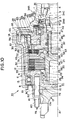
Fig. 1 is a sectional front elevation showing one half of a driving force
transmission system of the invention;
Fig. 2 is a sectional front elevation showing the other half of the
driving force transmission system of the invention;
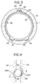
Fig. 3 is a side section taken along line III - III of Fig. 1 and shows a
construction of a cylindrical portion of an electromagnet and a cylindrical
portion of a casing;
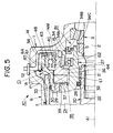
Fig. 4 is a section showing a portion of a construction a cam, ball and
a piston to be applied for applying a main clutch shown in Figs. 1 and 2;
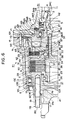
Fig. 5 is a sectional front elevation showing one half of another
example of the construction of a rotation stopping mechanism and first and
second bearings to be applied to the driving force transmission system of the
invention;
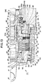
Fig. 6 is a sectional front elevation showing one half of a driving force
transmission system according to still another embodiment of the invention;
Fig. 7 is a sectional front elevation showing the other half of the
driving force transmission system of Fig. 6;
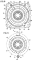
Fig. 8 is a righthand side elevation showing an essential portion of
the driving force transmission system of Fig. 6, that is a cover, an
electromagnet, a shaft and a rotor;
Fig. 9 is a righthand side elevation showing an example of the
construction of an opening of a differential carrier shown in Figs. 6 and 7;
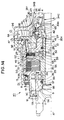
Fig. 10 is a sectional front elevation showing one half of a driving
force transmission system according to still another embodiment of the
invention;
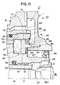
Fig. 11 is a sectional front elevation showing one half of a portion of
still another embodiment, in which the construction of the driving force
transmission system of Fig. 6 is partially modified;
Fig. 12 is a sectional front elevation showing one half of a driving
force transmission system according to still another embodiment of the
invention;
Fig. 13 is a sectional front elevation showing the other half of the
driving force transmission system of Fig. 12;
Fig. 14 is a sectional front elevation showing one half of a driving
force transmission system according to still another embodiment of the
invention;
Fig. 15 is a sectional front elevation showing one half of a portion of
another example of a sealing device to be used in the driving force
transmission system of the invention;
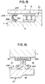
Fig. 16 is a sectional front elevation showing one half of a portion of
still another embodiment of the sealing device;
Fig. 17 is a sectional front elevation showing one half of a portion of a
construction, as used in the driving force transmission system of the invention,
in the vicinity of a stud bolt;
Fig. 18 is a sectional front elevation showing one half of a portion of
another construction of the stud bolt to be used in the invention;
Fig. 19 is a sectional front elevation showing a driving force
transmission system according to still another embodiment of the invention;
Fig. 20 is a longitudinal front section showing a portion of a driving
force transmission system according to still another embodiment of the
invention;
Fig. 21 is a schematic diagram showing a construction of a four-wheel
drive vehicle on which a driving force transmission system of the invention
is mounted;
Fig. 22 is a righthand section taken along line XXII - XXII of Fig. 20
and shows the driving force transmission system of the invention;
Fig. 23 is a longitudinal front section showing a portion of still
another embodiment of the driving force transmission system of Fig. 20, in
which the coil case of an electromagnet is fitted by another fitting
mechanism;
Fig. 24 is a longitudinal front section showing still another
embodiment of the driving force transmission system of Fig. 20, in which the
coil case of the electromagnet is fitted by still another fitting mechanism;
Fig. 25 is a skeleton diagram showing a vehicle, on which a driving
force transmission system according to the invention is mounted;
Fig. 26 is a section showing a portion of the state in which a coupling
case and a rotor of the driving force transmission system according to the
invention are screwed;
Fig. 27 is a section showing a portion of a pilot clutch constructing the
driving force transmission system of the invention;
Fig. 28 is a side elevation showing a clutch disc constructing the pilot
clutch shown in Fig. 27;
Fig. 29 is a section showing a portion of a driving force transmission
system according to still another embodiment of the invention;
Fig. 30 is a section showing a portion of another construction of the
pilot clutch shown in Fig. 29;
Fig. 31 is a partially omitted section showing a rotor or a magnetic
path establishing member constructing a first rotary member of the driving
force transmission system;
Fig. 32 is a section showing a portion of the state in which the
components of the rotor composing the driving force transmission system
are jointed to each other by an electron-beam welding;
Fig. 33 is a section showing a portion of a comparison of the state in
which the components of the rotor are jointed by another welding means;
Fig. 34 is an enlarged section showing still another embodiment of
the driving force transmission system;
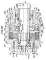
Fig. 35 is a section showing a driving force transmission system
according to still another embodiment of the invention;
Fig. 36 is an enlarged transverse section of a portion showing a
relation between a cam groove and cam followers in a first cam mechanism
constructing the driving force transmission system shown in Fig. 35;
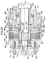
Fig. 37 is a section showing a driving force transmission system
according to still another embodiment of the invention; and
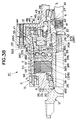
Fig. 38 is a partially omitted section showing a driving force
transmission system according to still another embodiment of the invention.
DETAILED DESCRIPTION OF THE PREFERRED EMBODIMENTS
The invention will be described in detail in connection with its
embodiments with reference to the accompanying drawings. Figs. 1 and 2
are sectional front elevations showing the halves of a driving force
transmission system K1 which is mounted on a standby four-wheel drive
vehicle. This driving force transmission system K1 is arranged between a
propeller shaft and a differential. Reference numeral 1 appearing in Figs.
1 and 2 designates a differential carrier which is irrotationally fixed. In
this differential carrier 1, there is arranged a drive pinion shaft 2 which is
to be rotated on an axis A1. In the inner circumference of the differential
carrier 1, there is fitted a bearing 3, by which the drive pinion shaft 2 is
rotatably supported.
To the drive pinion shaft 2, there are attached a sleeve 4 and a nut 5
which are located at the two sides of the bearing 3 in the direction of the axis
A1. The bearing 3 is clamped by the sleeve 4 and the nut 5 so that the
drive pinion shaft 2 and the differential carrier 1 are positioned in the
direction of the axis A1. Here in the differential carrier 1, there is
arranged the differential which is constructed of the well-known gear train.
On the open end of the differential carrier 1, on the other hand, there
is fixed a cylindrical cover 6 which is centered by the axis A1. From the
outside of the cover 6 to the inside of the cover 6 and to the inside of the
differential carrier 1, moreover, there is arranged a bottomed cylindrical
coupling case 7. This coupling case 7 is made of a non-magnetic material
such as an aluminum alloy. The coupling case 7 is formed of a
diametrically smaller cylindrical portion 9, a bottom portion 10, an annular
joint portion 11 and a diametrically larger cylindrical portion 12.
The diametrically smaller cylindrical portion 9 is arranged in an
opening 8 of the cover 6, and the outer end portion of the cover 6 in the
diametrically smaller cylindrical portion 9 is closed by the bottom portion
10. The annular joint portion 11 is extended to the outer circumferential
side from the inner side end portion of the cover 6 in the diametrically
smaller cylindrical portion 9. The diametrically larger cylindrical portion
12 is arranged toward the inner side of the differential carrier 1 from the
outer circumferential end of the joint portion 11.
In the diametrically smaller cylindrical portion 9, there is formed an
oil inlet 9A which extends therethrough in the direction of the axis A1.
This oil inlet 9A is provided for pouring the oil into the (later-described)
coupling oil chamber and is sealed liquid-tight by press-fitting a ball 9B in
the oil inlet 9A after pouring the oil. Moreover, the oil inlet 9A is caulked
at its entrance so that the ball 9B is prevented from coming out of the oil
inlet 9A by the pressure in the coupling oil chamber. Here, the outer end
face of the diametrically smaller cylindrical portion 9 is internally threaded
at 9C in its four portions on a circumference on the axis A1.
In the inner circumference of the end portion at the side of the
opening 8 of the cover 6, there is fixed a seal bearing 13. This seal bearing
13 is given the well-known structure in which a seal member 13C is fitted
between an inner race 13A and an outer race 13B. At the end face 14 of the
differential carrier 1 at the side of the cover 6, on the other hand, there is
formed a cylindrical portion 15 which is protruded on the axis A1 toward the
cover 6. On the outer circumference of the cylindrical portion 15, there is
fixed a seal bearing 16. This seal bearing 16 is given the well-known
construction in which a seal member 16c is fitted between an inner race 16A
and an outer race 16B so as to seal these races.
On the other hand, the seal bearings 13 and 16 are filled therein with
lubricating grease. Moreover, the inner race 13A of the seal bearing 13 is
mounted on the outer circumference of the diametrically smaller cylindrical
portion 9 of the coupling case 7, and the outer race 16B of the seal bearing
16 is mounted in the inner circumference of the end portion of the
diametrically larger cylindrical portion 12 at the side of the differential
carrier 1. In short, the coupling case 7 is so supported by the seal bearings
13 and 16 as to rotate on the axis A1.
On the end face of the diametrically smaller cylindrical portion 9 of
the coupling case 7 at the outer side of the cover 6, on the other hand, there
is fitted a flange 17. In this flange 17, there are formed four holes 17A on a
circumference on the axis A1. Moreover, bolts 18 are inserted into the individual
holes 17A and are driven into the internally threaded portions 9C
to fix the diametrically smaller cylindrical portion 9 and the flange 17.
This flange 17 is jointed to the (not-shown) propeller shaft. On the outer
circumference of the diametrically smaller cylindrical portion 9, there is
fitted a cylindrical dust deflector 19 for preventing the dust from coming
from the outside. On the other hand, the opening 8 is sealed by the seal
bearing 13.
In the cover 6, there is arranged a shaft 20 which is rotated on the
axis A1. In this shaft 20, there are formed recesses 22 and 23 which are
defined in the direction of the axis A1 by a partition 21. These recesses 22
and 23 are column-shaped spaces on the axis A1. In the inner
circumference of the recess 22 arranged at the side of the differential carrier
1, moreover, there is splined the leading end of the drive pinion shaft 2.
On the other hand, the axial length of the shaft 20 is set to such a
value that it extends from the open end of the differential carrier 1 to the
inside of the diametrically smaller cylindrical portion 9 of the coupling case
7. Between the inner circumference of the diametrically smaller
cylindrical portion 9 and the outer circumference of the end portion of the
shaft 20 at the side of the diametrically smaller cylindrical portion 9,
moreover, there is mounted a bearing 24 which supports the shaft 20
rotatably. Moreover, the bearing 24 is clamped between a snap ring 25
mounted in the inner circumference of the diametrically smaller cylindrical
portion 9 and a snap ring 26 mounted in the outer circumference of the shaft
20 thereby to position the shaft 20 and the coupling case 7 in the axial
direction.
Around the shaft 20, there is arranged an annular rotor 27. This
rotor 27 is given an axial length to reach the inside of the differential carrier
1 from the inside of the coupling case 7. The rotor 27 can rotate on the axis
A1 and is composed of: an inner cylindrical portion 28 having a generally
L-shaped radial section; an annular shielding member 29 fixed on the outer
circumference of the inner cylindrical portion 28; and an outer cylindrical
portion 30 fixed on the outer circumference of the shielding member 29.
The inner cylindrical portion 28 and the outer cylindrical portion 30
are made of a magnetic material such as iron, and the shielding member 29
is made of a non-magnetic material such as stainless steel. Moreover, the
outer cylindrical portion 30 of the rotor 27 is screwed into the inner
circumference of the coupling case 7 and is irrotationally fixed by the welding.
In other words, the rotor 27 is screwed in the rear end opening of the
coupling case 7 thereby to cover the opening. As a result, the coupling case
7 and the rotor 27 are integrally rotated.
In the inner circumference of the inner cylindrical portion 28 of the
rotor 27, on the other hand, there is fitted a metallic bushing 31. This
bushing 31 supports the shaft 20 so that the rotor 27 and the shaft 20 can
rotate relative to each other. Between the inner circumference of the inner
cylindrical portion 28 and the outer circumference of the shaft 20, moreover,
there is mounted an X-ring 32 which is made of a rubber elastomer. By
this X-ring 32, a liquid-tight seal is established between the shaft 20 and
the rotor 27. Between the outer circumference of the outer cylindrical
portion 30 and the inner circumference of the coupling case 7, moreover,
there is mounted an O-ring 33 which is made of a rubber elastomer. By
this O-ring 33, a liquid-tight seal is established between the rotor 27 and
the coupling case 7.
Between the bearing 3 and the cylindrical portion 15 in the inner
circumference of the differential carrier 1, still moreover, there is mounted
an oil seal 34, which is composed of an annular seal body 34A and a
reinforcing metal ring 34B embedded in the seal body 34A. A single seal
lip 34C is formed at the inner circumference side of the seal body 34A. By
this oil seal 34, a liquid-tight seal is established between the differential
carrier 1 and the rotor 27. In the differential carrier 1, moreover, there is
formed a differential oil chamber B1 which is sealed liquid-tight by the X-ring
32 and the oil seal 34. The drive pinion shaft 2 is arranged in the
differential oil chamber B1.
On the other hand, the space, as defined by the differential carrier 1,
the cover 6, the coupling case 7 and the rotor 27, is sealed liquid-right and
gas-tight from the surrounding space by the oil seal 34, the O-ring 33 and
the seal bearing 13, thereby to form an electromagnet housing chamber C1.
Moreover, the space, as defined by the coupling case 7, the shaft 20 and the
rotor 27 is sealed liquid-tight from the surrounding space by the O-ring 33
and the X-ring 32 thereby to form a coupling oil chamber D1.
In the electromagnet housing chamber C1, there is arranged an
electromagnet 35. This electromagnet 35 is equipped with an annular iron
core 36 made of a magnetic material, a coil 37 wound on the iron core 36,
and an electric wire 38 for feeding electric current to the coil 37. Between
the inner cylindrical portion 28 and the outer cylindrical portion 30 of the
rotor 27, there is formed an annular recess 39. The electromagnet 35 is
arranged in this recess 39.
Between a cylindrical portion 40 formed integrally with the iron core
36 at the side of the differential carrier 1 and the inner cylindrical portion
28 of the rotor 27, moreover, there is mounted a (radial) bearing 41 so that
the electromagnet 35 and the rotor 27 can rotate relative to each other.
Moreover, the electromagnet 35 and the rotor 27 are positioned in the axial
direction and in the radial direction by the bearing 41, by a snap ring 42
mounted on the inner cylindrical portion 28 and by a snap ring 43 mounted
on the iron core 36. Thus, an (air) gap E1 between the inner circumference
of the iron core 36 and the inner cylindrical portion 28 and an (air) gap F1
between the outer circumference of the iron core 36 and the outer cylindrical
portion 30 are set by the single bearing 41.
On the other hand, the electromagnet 35 and the differential carrier 1
are so jointed to each other by a rotation stopping mechanism that they
cannot rotate relative to each other. This rotation stopping mechanism
will be described with reference to Fig. 3. Fig. 3 presents a radial section
showing the cylindrical portion 40 of the iron core 36 and the cylindrical
portion 15 of the differential carrier 1. On the outer circumference of the
cylindrical portion 40 of the iron core 36, there are formed a plurality of
ridges 44 which are protruded outward. Moreover, the electric wire 38 is
buried in one of the ridges 44.
In the inner circumference of the cylindrical portion 15 of the
differential carrier 1, on the other hand, there are formed a plurality of
grooves 45 which are positioned to correspond to the ridges 44. Moreover,
the cylindrical portion 40 of the iron core 36 is arranged in the cylindrical
portion 15 of the differential carrier 1 so that the ridges 44 are individually
fitted in the grooves 45. These engaging forces between the ridges 44 and
the grooves 45 prevent the relative rotations between the differential carrier
1 and the electromagnet 35. Here, the ridges 44 and the grooves 45 may be
individually provided by at least one. These cylindrical portion 15, ridges
44 and grooves 45 are arranged to face an opening 6A of the cover 6 and an
opening 1A of the differential carrier 1.
Thus, the rotation stopping mechanism for preventing the relative
rotation between the differential carrier 1 and the electromagnet 35 is
arranged radially outside of the bearing 41 on the axis A1, and the seal
bearing 16 is arranged radially outside of the rotation stopping mechanism.
In the cylindrical portion 15, there is formed a cut-off portion 46 for
providing the communication between one groove 45 and the outer
circumference of the cylindrical portion 15. This cut-off portion 46 is
provided for passing the electric wire 38 when the cylindrical portion 40 of
the electromagnet 35 is inserted into the cylindrical portion 15 of the
differential carrier 1.
In the end face 14 of the differential carrier 1 at the side of the cover
6, there is formed a groove 14M, along which the electric wire 38 is
arranged. This electric wire 38 is guided through a through groove 47, as
formed in the abutting faces of the differential carrier 1 and the cover 6, to
the outside of the differential carrier 1 and the cover 6 to be connected with
a not-shown power source. An annular shim 48 is fitted on the outer
circumference of the cylindrical portion 15 of the differential carrier 1, and
the seal bearing 16 is made to abut against the end face of the shim 48.
Moreover, the electric wire 38, as threaded in the groove 14, is held by the
shim 48 so that it is fixed.
In the coupling oil chamber D1, there are arranged a pilot clutch 49 to
be applied/released by the electromagnetic force of the electromagnet 35,
and a main clutch 50 to be applied in association with the application of the
pilot clutch 49 to transmit the torque of the coupling case 7 to the shaft 20.
The pilot clutch 49 is equipped with an armature 51, a plurality of
clutch discs 52 and a plurality of clutch plates 54. The armature 51 is
arranged at a predetermined spacing from the rotor 27. On the other
hand, the clutch discs 52 are arranged between the armature 51 and the
rotor 27. Moreover, the clutch discs 52 and the clutch plates 54 are
arranged alternately of each other. The outer circumferences of these
armature 51 and clutch discs 52 are splined in the inner circumference of
the coupling case 7.
On the other hand, an annular cam 53 is mounted on the outer
circumference of the shaft 20, and the inner circumference of the clutch
plate 54 is splined on the outer circumference of the cam 53. The annular
cam 53 and the shaft 20 are constructed to rotate relative to each other.
Between the cam 53 and the inner cylindrical portion 28 of the rotor 27, on
the other hand, there is arranged a thrust bearing 20A. This thrust
bearing 20A is provided for bearing a thrust load to act on the cam 53 and
for keeping the rotor 27 and the can, 53 rotatable relative to each other.
On the other hand, the main clutch 50 is arranged between the pilot
clutch 49 and the diametrically smaller cylindrical portion 9 of the coupling
case 7. This main clutch 50 is equipped with a plurality of clutch discs 55
and a plurality of clutch plates 56 arranged alternately of the clutch discs
55. The outer circumferences of the clutch discs 55 are splined in the inner
circumference of the coupling case 7, and the inner circumferences of the
clutch plates 56 are splined in the outer circumference of the shaft 20.
Between the main clutch 50 and the pilot clutch 49, moreover, there
is arranged an annular piston 57. This piston 57 is splined in the outer
circumference of the shaft 20. As shown in Fig. 4, grooves 58 and 59
having trapezoidal sections are formed in the confronting faces of the piston
57 and the cam 53. Oppositely sloped pressure receiving faces 58A and
59A are formed in the grooves 58 and 59, respectively. Balls 60 are
arranged in the grooves 58 and 59.
The coupling oil chamber D1 is filled with the coupling oil which is
characterized to keep satisfactory the wear resistance, the oil cut and the
judder resistance of the clutch discs 52 and 55 and the clutch plates 54 and
56. This coupling oil is prepared by adding various kinds of additives to
mineral lubricating oil. On the other hand, the differential oil chamber B1
is filled with the lubricating oil which is characterized to have little viscosity
change due to the temperature, a low fluid point, an excellent heat
resistance, an excellent oxidation stability and an excellent load resistance.
This lubricating oil is exemplified by lubricating mineral oil.
Here will be described the correspondence between the construction
of the driving force transmission system K1 and the invention.
Specifically, the differential carrier 1 and the cover 6 correspond to a
stationary member of the invention, and the coupling case 7 and the rotor
27 correspond to a first rotary member of the invention. On the other
hand; the shaft 20 and the drive pinion shaft 2 correspond to a second rotary
member of the invention; the pilot clutch 49 and the main clutch 50
correspond to a clutch mechanism of the invention; and the outer cylindrical
portion 30 and the inner cylindrical portion 28 correspond to a magnetic
member of the invention. On the other hand, the rotor 27, the armature 51
and the electromagnet 35 correspond to electromagnetic control means of
the invention. On the other hand, the cam 53, the piston 57 and the balls
60 correspond to a cam mechanism of the invention.
Moreover, the cylindrical portion 15 of the differential carrier 1, the
grooves 45 formed in the cylindrical portion 15, the cylindrical portion 40 of
the iron core 36 and the ridges 44 formed on the cylindrical portion 40
correspond to a rotation stopping mechanism or a positioning mechanism of
the invention. On the other hand, the bearing 41 corresponds to a first
bearing of the invention, and the seal bearing 16 corresponds to a second
bearing of the invention. On the other hand, the seal bearing 13
corresponds to a third bearing of the invention.
On the other hand, the differential carrier 1, the cover 6, the coupling
case 7, the O-ring 33, the oil seal 34, the seal bearings 13 and 16, the rotor
27, the shaft 20 and the X-ring 32 correspond to an isolating mechanism of
the invention, and the coupling oil chamber D1 corresponds to a clutch
housing chamber of the invention.
Moreover, the coupling 7, the pilot clutch 49, the main clutch 50 and
the electromagnet 35 thus integrally assembled construct one unit.
Here will be described the actions of the driving force transmission
system K1 having the construction thus far described. At first, when no
electric current is fed to the electromagnet 35, the pilot clutch 49 and the
main clutch 50 are released. As a result, the torque, as transmitted from
the not-shown propeller shaft to the coupling case 7, is not transmitted to
the shaft 20 and the drive pinion shaft 2.
When the electric current is fed to the electromagnet 35, on the other
hand, the magnetic flux passes through the iron core 36, the outer
cylindrical portion 30, the armature 51 and the inner cylindrical portion 28
to establish a magnetic circuit. As a result, the armature 51 is moved
toward the outer cylindrical portion 30 and the inner cylindrical portion 28
by the electromagnetic force (or the magnetic attraction). Then, the clutch
discs 52 and the clutch plates 54 are applied. As a result, the torque of the
coupling case 7 is transmitted through the pilot clutch 49 to the cam 53.
When the torque is transmitted to the cam 53, the can, 53 and the
piston 57 are rotated relative to each other in the direction of arrow, as
shown in Fig. 4. Then, the balls 60 are pushed onto the pressure receiving
faces 58a and 59A, as sloped in the same direction, so that the force acts for
the pressure receiving faces 58A and 59A to push the balls 60 out of the
grooves 58 and 59. As a result, there is established a thrust load which is
directed to move the cam 53 and the piston 57 away from each other in the
direction of the axis A1.
Here, the cam 53 is received by the thrust bearing 20A so that it is
prevented from moving toward the rotor 27. As a result, the piston 57 is
pushed toward the main clutch 50 by the thrust load thereby to apply the
clutch discs 55 and the clutch plates 56. In other words, the applying force
of the pilot clutch 49 is amplified by the cam 53, the balls 60 and the piston
57 and is transmitted to the main clutch 50. When the main clutch 50 is
applied, the torque of the coupling case 7 is transmitted through the main
clutch 50 to the shaft 20 and the drive pinion shaft 2. Here, the main
clutch 50 and the pilot clutch 49 are cooled, when applied to generate heat,
with the oil which is confined in the coupling oil chamber D1.
According to the driving force transmission system K1, moreover, the
gaps E1 and F1 are set by the bearing 41 or the single component which is
mounted between the inner cylindrical portion 28 and the electromagnet 35.
Here, the bearing 41 or the radial bearing is intrinsically given a sizing
accuracy capable of accurately setting the relative positions of the member
to be mounted and the support member in the radial direction. As a result,
the setting accuracy of the gaps E1 and F1 is improved as much as possible.
It is, therefore, easy to control the applying force (or the torque
capacity) between the clutch discs 52 and the clutch plates 54. As a result,
it is easy to control the applying force (or the torque capacity) between the
clutch discs 55 and the clutch plates 56. In short, the function to transmit
the driving force to be transmitted from the coupling case 7 to the shaft 20 is
improved.
On the other hand, the components such as the bearing 41, the
rotation stopping mechanism and the seal bearing 16 are arranged in
substantially identical positions in the direction of the axis A1 and with
overlaps in the radial direction. As a result, the space for arranging those
components in the axial direction can be reduced as much as possible to
reduce the size of the driving force transmission system K1 in the direction
of the axis A1. Here, it is possible to adopt a construction in which the
bearing 41, the rotation stopping mechanism and the seal bearing 16 are
partially overlapped in the axial direction.
In this embodiment, moreover, one axial end of the coupling case 7 is
supported by the seal bearing 16, and the other axial end of the coupling
case 7 is supported by the seal bearing 13. As a result, the coupling case 7
is highly accurately positioned in the radial direction thereby to suppress
the vibration of the coupling case 7 and the noise (or the booming noise) to
be caused by the vibration.
Moreover, the rotation stopping mechanism for preventing the
relative rotation between the electromagnet 35 and the differential carrier 1
is equipped with the ridges 44 formed on the electromagnet 35 itself and the
grooves 45 formed in the differential carrier 1 itself, and establishes the
rotation stopping function by the engaging forces between the ridges 44 and
the grooves 45.
Here will be described the works of assembling the unit in the
differential carrier 1. Specifically, the electromagnet 35 and the
differential carrier 1 are moved relative to each other in the axial direction
to insert the cylindrical portion 40 of the electromagnet 35 into the
cylindrical portion 15 of the differential carrier 1. By these simple works,
it is possible to stop the rotation of the electromagnet 35 and the differential
carrier 1. As a result, the driving force transmission system K1 can be
assembled easily and promptly.
In order to prevent the relative rotation between the electromagnet
35 and the differential carrier 1, on the other hand, no other part need be
attached to reduce the number of parts of the driving force transmission
system K1. As a result, the assembling works of the driving force
transmission system K1 can be further improved to reduce the weight of the
driving force transmission system K1.
On the other hand, the electromagnet housing chamber C1 and its
surrounding space are sealed fluid-tight (i.e., liquid-tight and gas-tight) by
the differential carrier 1, the cover 6, the coupling case 7, the oil seal 34, the
O-ring 33 and the seal bearing 13. Moreover, the electromagnet 35 and the
gaps E1 and F1 are arranged in the electromagnet housing chamber C1.
This arrangement suppresses the entrance of a foreign substance such as
the differential oil confined in the differential oil chamber B1 or the wear
powder, as produced by the meshing engagement of the gears, into the
electromagnet housing chamber C1.
By the O-ring 33, on the other hand, the coupling oil, as confined in
the coupling oil chamber D1, is prevented from entering the electromagnet
housing chamber C1. By the seal bearing 13, moreover, the water or the
foreign substance outside of the differential carrier 1 is prevented from
entering the electromagnet housing chamber C1. Still moreover, the
lubricating grease, as confined in the seal bearing 13 and the seal bearing
16, is prevented from entering the electromagnet housing chamber C1.
As a result, only the air is present in the gaps E1 and F1, which are
formed between the iron core 36 of the electromagnet 35 and the outer
cylindrical portion 30 and the inner cylindrical portion 28 of the rotor 27,
and it is possible to prevent the water, oil or foreign substance from entering
the (air) gaps E1 and F1. As a result, the magnetic permeabilities of the
gaps E1 and F1 can be kept homogeneous to stabilize the magnetic
attraction to be established by the electromagnet 35. In other words, the
relation between the current to be fed to the electromagnet 35 and the
applying force of the pilot clutch 49 is stabilized. As a result, the applying
force of the main clutch 50 is easily controlled to improve the driving force
transmitting performance of the driving force transmission system K1.
In this embodiment, moreover, the coupling oil chamber D1 and the
differential oil chamber B1 are sealed liquid-tight. On the other hand, the
electromagnet housing chamber C1 is an air chamber, and the through
groove 47 is formed in a position to face the electromagnet housing chamber
C1. The electric wire 38 is inserted into the through groove 47. As a
result, the oil has no possibility to leak out of the through groove 47 so that
no special seal mechanism need be provided in the through groove 47. As a
result, the assembly of the differential carrier 1 and the cover 6 is simplified
to improve the workability.
Since no seal is required for the through groove 47, on the other hand,
the through groove 47 can be formed in the abutting faces between the
differential carrier 1 and the cover 6. As a result, when the electromagnet
35 is to be fitted in the differential carrier 1 and the cover 6, it is sufficient to
form the through hole 47 which is sized to admit the electric wire 38. In
other words, a through hole as large as to admit the (not-shown) socket
mounted on the leading end of the electric wire 38 need not be formed for
the differential carrier 1 or the cover 6, so that the facility of design in space
is improved.
In this embodiment, on the other hand, the coupling oil chamber D1,
as sealed liquid-fight by the O-ring 33 and the X-ring 32, is formed in the
coupling case 7. Moreover, the pilot clutch 49 and the main clutch 50 are
arranged in the coupling oil chamber D1. On the other hand, the coupling
oil chamber D1 is filled with the coupling oil. Here, the X-ring 32 is
excellent in the pressure resistance because of its structure. This
suppresses the entrance of the coupling oil of the coupling oil chamber D1
into the differential oil chamber B1 and the entrance of the differential oil of
the differential oil chamber B1 into the coupling oil chamber D1.
As a result, it is possible to separately select and fill the oil matching
the characteristics demanded by the coupling oil chamber D1 and the oil
matching the characteristics and performance demanded by the differential
oil chamber B1. Specifically, the coupling oil chamber D1 is filled with the
coupling oil which is characterized to keep satisfactory the wear resistance,
the oil cut and the judder resistance of the clutch plates and discs composing
the pilot clutch 49 and the main clutch 50. This coupling oil is prepared by
adding various additives to lubricating mineral oil. On the other hand, the
differential oil chamber B1 is filled with the lubricating oil which has little
viscosity change due to the temperature, a low fluid point, an excellent heat
resistance, an excellent oxidation stability and an excellent load resistance.
This lubricating oil is exemplified by lubricating mineral oil.
Moreover, the place for mounting the driving force transmission
system K1 is located in the transmission, between the propeller shaft and
the differential or on the transfer of a four-wheel drive vehicle. No matter
what place the driving force transmission system K1 might be mounted on,
the coupling oil matching the characteristics or performance of the pilot
clutch 49 or the main clutch 50 can be selected independently of the
matching with the function and characteristics demanded for the remaining
power transmission system and its components. As a result, the degree of
freedom for the mounting position and layout of the driving force
transmission system K1 is increased.
In this embodiment, on the other hand, there is formed the single
unit which is equipped with the coupling case 7, the pilot clutch 49 and the
main clutch 50. Moreover, the torque transmission characteristics such as
the wear resistance, the oil cut and the judder resistance of the pilot clutch
49 or the main clutch 50 can be managed or evaluated by the single unit.
In the vehicle manufacturing process, therefore, the performance is easily
managed at the unit before the step at which the driving force transmission
system K1 is mounted on the vehicle.
Moreover, the shaft 20 and the rotor 27 are sealed liquid-tight by the
X-ring 32. As a result, the foreign substance such as the wear powder, as
produced at the side of the differential oil chamber B1, is prevented from
entering the coupling oil chamber D1. As a result, no foreign substance
will possibly enter the clearances between the clutch discs 52 and the clutch
plates 54 of the pilot clutch 49 or between the clutch discs 55 and the clutch
plates 56 of the main clutch 50. As a result, the applying/releasing actions
of the pilot clutch 49 and the main clutch 50 are stabilized while preventing
the wear or damage of the clutch discs and plates to improve the driving
force transmitting function and the durability.
In the shaft 20, on the other hand, there is formed the recess 23 which
is opened into the coupling oil chamber D1. This recess 23 increases the
capacity of the coupling oil chamber D1. In other words, the coupling oil is
accommodated by making use of the recess 23 of the shaft 20, as arranged in
the coupling case 7. Without enlarging the size of the coupling case 7,
therefore, the capacity for the coupling oil can be made as high as possible to
improve the durability of the coupling oil.
Fig. 5 is a section showing a portion of another embodiment of the
driving force transmission system K1. In Fig. 5, the support mechanism
for the rotor 27 and the support mechanism for the electromagnet 35 are
different from those of the embodiment of Figs. 1 to 4. In Fig. 5, a plurality
of ridges 61 are formed on the outer circumference of the cylindrical portion
15 which is formed in the differential carrier 1. On the inner
circumference of the cylindrical portion 15, on the other hand, there is fixed
a bearing 62 for supporting the rotor 27 rotatably.
In the inner circumference of the outer cylindrical portion 30, on the
other hand, there is fixed a seal bearing 63 for supporting the electromagnet
35 rotatably. Moreover, this seal bearing 63 sets the gaps E1 and F1
between the iron core 36 of the electromagnet 35 and the inner cylindrical
portion 28 and the outer cylindrical portion 30.
In the inner circumference of the cylindrical portion 40 of the iron
core 36, moreover, there are formed a plurality of grooves 64 which are
made to engage with the ridges 61. By these engagements between the
grooves 64 and the ridges 61, the differential carrier 1 and the
electromagnet 35 are stopped from their relative rotation. These ridges 61
and grooves 64 are arranged to face the openings 1A and 6A. Around the
outer circumference of the bearing 62 on the axis A1, moreover, there are
arranged the cylindrical portion 15, the ridges 61, the cylindrical portion 40
and the grooves 64. Around the outer circumference of the cylindrical
portion 40 in the radial direction, on the other hand, there is arranged the
seal bearing (of a radial bearing) 63. The remaining construction is similar
to that of the embodiment of Figs. 1 and 2.
Here will be described the correspondences between the construction
of Fig. 5 and the invention. The seal bearing 63 corresponds to the first
bearing of the invention; the cylindrical portion 15, the cylindrical portion
40, the ridges 61 and the grooves 64 correspond to the rotation stopping
mechanism or the positioning mechanism of the invention; and the bearing
62 corresponds to the second bearing of the invention. Effects similar to
those of the embodiment of Figs. 1 and 2 are achieved in this embodiment of
Fig. 5, too.
Here in the embodiments of Figs. 1 to 5, there may be adopted a
construction in which the electromagnet housing chamber C1 is filled with
cooling oil. In this construction, the cooling oil is sealed by the seal bearing
16 so that it does not leak to the outside of the differential carrier 1 and the
cover 6.
By the O-ring 33 and the oil seal 34, on the other hand, the
electromagnet housing chamber C1, the differential oil chamber B1 and the
coupling oil chamber D1 are sealed liquid-tight. As a result, the cooling oil,
as filling the electromagnet housing chamber C1, will leak into neither the
differential oil chamber B1 nor the coupling oil chamber D1. Moreover, the
main clutch 50, the pilot clutch 49 and the electromagnet 35 are cooled with
the cooling oil.
In the embodiments of Figs. 1 to 5, moreover the seal bearings 41 and
62 can be replaced by bearings having no seal. This is because the
differential oil chamber B1 and the electromagnet housing chamber C1 are
sealed liquid-tight by the oil seal 34 so that the oil, as filling the differential
oil chamber B1, has no possibility of leaking into the electromagnet housing
chamber C1.
Figs. 6 and 7 are sectional front elevations showing the halves of the
driving force transmission system K1. The embodiment of Figs. 1 and 2
and the embodiment of Figs. 6 and 7 are different, when compared, in the
construction of the electromagnet, in the construction of the rotation
stopping mechanism for the electromagnet, in the construction of the fixing
mechanism for the coupling case and the flange, and in the joint mechanism
for the coupling case and the rotor. Here will be specifically described
those differences.
At first, a cylindrical portion 65 on the axis A1 is formed in the iron
core 36 of the electromagnet 35, and the (radial) bearing 41 is fitted between
the cylindrical portion 65 and the rotor 27. Moreover, the electromagnet 35
and the rotor 27 are positioned in the direction of the axis A1 by the bearing
41, the snap ring 42 fitted on the inner cylindrical portion 28, and the snap
ring 43 fitted on the iron core 36.
In the inner circumference of the differential carrier 1, on the other
hand, there is formed an annular recess 66 on the axis A1. The cylindrical
portion 65 is fitted in the inner circumference of the recess 66. In short, a
centering location is made of the recess 66 and the cylindrical portion 65.
Moreover, the bearing 41 and the recess 66 are arranged to overlap in the
radial direction. As a result, the iron core 36 is positioned in the radial
direction by the recess 66 and the bearing 41. Thus, the gap E1 is set
between the inner circumference of the iron core 36 and the inner
cylindrical portion 28, and the gap F1 is set between the outer
circumference of the iron core 36 and the outer cylindrical portion 30.
Between the end face of the recess 66 and the cylindrical portion 65,
on the other hand, there are arranged an annular shim 67 and an annular
disc spring 68. The iron core 36 is urged leftward, as shown in the
Drawings, by the elastic force of the disc spring 68.
Fig. 8 is a righthand end face showing the cover 6, the electromagnet
35 and the rotor 27. A protrusion 69 is formed on a portion of the outer
circumference of the iron core 36, and a cut-off portion 70 is formed in the
protrusion 69. In the abutting end face of the cover 6 against the
differential carrier 1, on the other hand, there is formed a hole 71. In this
hole 71, there is so fitted a rotation stopping pin 72 that its leading end is
arranged in the cut-off portion 70.
The relative rotation between the cover 6 and the iron core 36 is
prevented by the engagement between the rotation stopping pin 72 and the
protrusion 69. In short, the hole 71, the rotation stopping pin 72, the
protrusion 69 and the cut-off portion 70 construct the rotation stopping
mechanism. In this embodiment, moreover, this rotation stopping
mechanism is arranged to face the openings 1A and 6A.
In the outer circumference of the cover 6, moreover, there are formed
a plurality of axial holes 6B. In the vicinity of the axial holes 6B, on the
other hand, there are embedded a plurality of knock pins 6C. By inserting
these knock pins 6C into the (not-shown) holes formed in the differential
carrier 1, moreover, the cover 6 and the differential carrier 1 are positioned
in the circumferential direction on the axis A1.
When the cover 6 and the differential carrier 1 are positioned in the
circumferential direction on the axis A1, moreover, the axial holes 6B and a
plurality of (not-shown) internal threads formed in the differential carrier 1
are arranged in positions to confront each other. Here, the (not-shown)
bolts are individually inserted into the axial holes 6B and fastened to fix the
cover 6 and the differential carrier 1.
With the coil 37 of the electromagnet 35, on the other hand, there is
connected through a bobbin 73 an electric wire 74. This electric wire 74 is
provided for feeding the electric current to the coil 37.
The bobbin 73 and the protrusion 69 are arranged, as shown in Fig. 8,
in positions circumferentially different from that of the iron core 36.
Specifically, the bobbin 73 and the protrusion 69 are arranged in positions
of about 180 degrees.
In the cover 6, moreover, there is formed a hole 75, in which is fitted a
grommet 76 attached to the electric wire 74. The hole 75 is arranged in a
position of about 180 degrees with respect to the hole 71 in the
circumferential direction of the cover 6. Here, an adhesive 77 is buried in
the hole 75 outside of the grommet 76. Moreover, the relative positions
between the bobbin 73 and the protrusion 69 and between the hole 71 and
the hole 75 in the circumferential direction need not be spaced by 180
degrees.
Here will be described the fixing mechanism for the coupling case 7
and the flange 17. As shown in Fig. 6, the coupling case 7 and the flange
17 are fixed by stud bolts 78. Four stud bolts 78 are arranged in the
circumferential direction. Each stud bolt 78 has an embedded side
externally threaded portion 79 and a nut side externally threaded portion
80 in its longitudinal direction. Moreover, the embedded side externally
threaded portion 79 is set to a larger external diameter than that of the nut
side externally threaded portion 80.
The embedded side externally threaded portion 79 is embedded in the
internally threaded portion 9C. By bringing the leading end of the
embedded side externally threaded portion 79 into the bottom end of the
internally threaded portion 9C, moreover, the stud bolts 78 and the
diametrically smaller cylindrical portion 9 are positioned in the screwing
direction.
The stud bolts 78 are inserted into holes 17A of the flange 17.
Moreover, nuts 81 are screwed on the nut side externally threaded portions
80 and are fastened to fix the coupling case 7 and the flange 17 to each
other. Here, a washer 82 is sandwiched between the flange 17 and the nut
81.
Here will be described the joint mechanism for the coupling case 7
and the rotor 27. On the outer circumference of the outer cylindrical
portion 30, there is screwed a nut member 83. This nut member 83 and the
coupling case 7 are held in abutment at their confronting faces. When the
coupling case 7 is pushed rightward of the Drawings, a reaction responding
to the load is established at the nut member 83. As a result, the movement
of the rotor 27 relative to the coupling case 7 is suppressed by the looseness
between the coupling case 7 and the rotor 27. As a result, the fluctuation of
the transmission torque of the main clutch 50 and the pilot clutch 49 is
suppressed by the load of the coupling case 7 in the axial direction. The
remaining construction is similar to that of the embodiment of Figs. 1 and 2.
Here will be described the correspondences between the construction
of Figs. 6 and 7 and the construction of the invention. Specifically, the
differential carrier 1 and the cover 6 correspond to the casing or the
stationary member of the invention, and coupling case 7 and the rotor 27
correspond to the first rotary member of the invention. Moreover: the shaft
20 and the drive pinion shaft 2 correspond to the second rotary member of
the invention; the pilot clutch 49 and the main clutch 50 correspond to the
clutch mechanism of the invention; and the outer cylindrical portion 30 and
the inner cylindrical portion 28 correspond to the magnetic member of the
invention.
Moreover, the protrusion 69, the cut-off portion 70 and the iotation
stopping pin 72 correspond to the rotation stopping mechanism or the
positioning mechanism of the invention. Still moreover, the bearing 41
corresponds to the first bearing of the invention, and the cylindrical portion
65 and the recess 66 correspond to the positioning mechanism of the
invention. In addition, the coupling case 7 corresponds to the front cover of
the invention, and the rotor 27 corresponds to the rear housing of the
invention.
In the driving force transmission system K1 shown in Figs. 6 and 7,
too, the transmission or interruption of the torque is controlled depending
upon whether or not the electric current is fed to the electromagnet 35. In
the driving force transmission system K1 shown in Figs. 6 and 7, moreover,
the electromagnet 35 and differential carrier 1 are positioned in the radial
direction by fitting the recess 66 and the cylindrical portion 65. Moreover,
the gaps E1 and F1 are set by the single bearing 41. Here, the bearing 41
is intrinsically given a sizing accuracy capable of accurately setting the
relative positions between the member to be mounted and the support
member in the radial direction, so that the setting accuracy of the gaps E1
and F1 is improved as high as possible. As a result, the applying force of
the main clutch 50, i.e., the torque capacity is easily controlled to improve
the transmission function of the driving force to be transmitted from the
coupling case 7 to the shaft 20 and the drive pinion shaft 2.
In the embodiment of Figs. 6 and 7, on the other hand, the bearing 41,
the cylindrical portion 65 and the recess 66 are arranged to overlap in the
radial direction. In other words, the bearing 41, the cylindrical portion 65
and the recess 66 are arranged concentrically of the axis A1. As a result,
the space for arranging the bearing 41, the cylindrical portion 65 and the
recess 66 is restricted in the direction of the axis A1. As a result, the size of
the driving force transmission system K1 can be made as small as possible
in the axial direction.
In the embodiment of Figs. 6 and 7, moreover, the electromagnet 35 is
positioned in the radial direction relative to the differential carrier 1 by
fitting the cylindrical portion 65 and the recess 66. In short, no part such
as the bearing is required for positioning the differential carrier 1 and the
electromagnet 35 in the radial direction. As a result, the number of parts
of the driving force transmission system K1 can be suppressed to reduce the
number of steps for manufacturing the driving force transmission system
K1, to lighten the driving force transmission system K1 and to lower the
cost for manufacturing the driving force transmission system K1.
Here will be described a first working example of assembling the
driving force transmission system K1. In this first assembling example, a
unit, as composed of the shaft 20, the coupling case 7, the main clutch 50,
the pilot clutch 49, the rotor 27, the electromagnet 35, the bearing 24 and
the bearing 41, is attached in advance to the differential carrier 1. After
this, the cover 6 and the differential carrier 1 are fixed.
When the cover 6 and the differential carrier 1 are jointed to each
other, more specifically, the cover 6 and the differential carrier 1 and the
unit are relatively moved in the axial direction so that the unit is inserted
through the opening 6A into the cover 6. In this embodiment, the
electromagnet 35, the protrusion 69 and the rotation stopping pin 72 are
arranged to face the opening 1A and the opening 6A.
This enables the worker to observe the electromagnet 35, the
protrusion 69 and the rotation stopping pin 72 visually from the outside of
the cover 6 and the differential carrier 1 immediately before the end face of
the cover 6 and the end face of the differential carrier 1 comes into
abutment. In other words, it is possible to confirm the phases of the
electromagnet 35 and the cover 6 in the circumferential direction on the axis
A1, specifically the phases of the rotation stopping pin 72 and the cut-off
portion 70 in the circumferential direction.
When the rotation stopping pin 72 and the cut-off portion 70 are out
of phase in the circumferential direction, the differential carrier 1 and the
cover 6 can be stopped while rotating the electromagnet 35. By this
rotation of the electromagnet 35, the rotation stopping pin 72 and the cut-off
portion 70 can be corrected in phase in the circumferential direction on the
axis A1. Here, the differential carrier 1 and the cover 6 are positioned in
the circumferential direction with reference to the knock pin 6C of the cover
6 and the (not-shown) hole of the differential carrier 1.
After this, the cover 6 and the differential carrier 1 are moved in the
axial direction until the relative movement between the cover 6 and the
differential carrier 1 is ended with their end faces coming into abutment.
After the end of the relative movement between the cover 6 and the
differential carrier 1, the rotation stopping pin 72 is inserted in the cut-off
portion 70. As a result, the rotations of the cover 6 and the electromagnet
35 are fixed by the engaging force between the rotation stopping pin 72 and
the protrusion 69. Moreover, the (not-shown) bolts are inserted into the
axial holes 6B and fastened to fix the differential carrier 1 and the cover 6.
In this embodiment, as described hereinbefore, the electromagnet 35,
the protrusion 69 and the rotation stopping pin 72 can be visually observed
from the outside of the cover 6 and the differential carrier 1 before the
abutment between the end face of the cover 6 and the end face of the
differential carrier 1. When the electromagnet 35 and the cover 6 are out
of phase in the circumferential direction, moreover, the phases of the
rotation stopping pin 72 and the cut-off portion 70 can be corrected in the
circumferential direction not by moving the differential carrier 1, the cover
6 and the unit in the axial direction but merely by rotating the
electromagnet 35 as it is. As a result, the works of positioning the
electromagnet 35 and the cover 6 in the circumferential direction on the axis
A1 can be performed easily and promptly to improve the assembling
workability for the driving force transmission system K1.
Here will be described a second working example of assembling the
driving force transmission system K1. This second assembling example is
also applied to the case in which the construction of the differential carrier 1
is slightly different from that of the embodiment of Figs. 6 and 7. As shown
in Fig. 9, more specifically, grooved portions 1B and 1C are formed to
protrude outward in the generally circular opening 1A of the differential
carrier 1. These grooved portions 1B and 1C are arranged at a spacing of
about 180 degrees with respect to the circumferential direction of the
opening 1A.
Moreover, the protrusion 69 is arranged in the grooved portion 1B,
and the electric wire 74 is arranged in the grooved portion 1C. In this
construction, the electric wire 74, the protrusion 69 and the grooved
portions 1B and 1C correspond to the positioning mechanism of the
invention.
In this second assembling example, the unit, as prepared by
assembling the shaft 20, the coupling case 7, the main clutch 50, the pilot
clutch 49, the rotor 27, the electromagnet 35, the bearing 24 and the bearing
41 integrally, is assembled in advance with the cover 6, and the cover 6 and
the differential carrier 1 are then assembled.
At first, the unit and the cover 6 are relatively moved in the axial
direction so that the unit is housed through the opening 6A in the cover 6.
In this embodiment, before the end of the positioning the cover 6 and the
unit in the axial direction, the electromagnet 35, the protrusion 69 and the
rotation stopping pin 72 can be visually observed from the outside of the
cover 6. Moreover, it is possible to confirm the phases of the electromagnet
35 and the cover 6 in the circumferential direction, that is, the phases of the
rotation stopping pin 72 and the cut-off portion 70 in the circumferential
direction.
Here, the rotation stopping pin 72 and the cut-off portion 70 may be
out of phase in the circumferential direction. In this case, the rotation
stopping pin 72 and the cut-off portion 70 can be brought into phase in the
circumferential direction neither by moving the cover 6 and the
electromagnet 35 relatively in the axial direction nor by extracting any part
already housed in the cover 6 but by merely rotating the electromagnet 35.
The positioning of the cover 6 and the unit in the axial direction is then
ended by moving the cover 6 and the unit again in the axial direction.
At the end of positioning the cover 6 and the unit in the axial
direction, the rotation stopping pin 72 is inserted in the cut-off portion 70.
As a result, the rotations of the cover 6 and the electromagnet 35 are
stopped by the engaging forces between the rotation stopping pin 72 and the
protrusion 69. Then, the electric wire 74 is inserted into the hole 75 and
extracted out of the cover 6, and the grommet 76 is fitted in the hole 75.
After this, the (not-shown) connector may be attached to the end portion of
the electric wire 74.
By these works, the cover 6 and the unit are assembled, and the cover
6 and the unit, and the differential carrier 1 are then relatively moved in
the axial direction. Here, the differential carrier 1 and the cover 6 are
positioned in the circumferential direction with reference to either the
knock pills 6C of the cover 6 and the (not-shown) holes of the differential
carrier 1, or the axial holes 6B of the cover 6 and the (not-shown) internal
threads of the differential carrier 1.
Now, the positioning of the cover 6 and the unit in the circumferential
direction is ended by the works described above. As a result, the
positioning of the differential carrier 1 and the unit is indirectly performed
by the circumferential positioning of the differential carrier 1 and the cover
6. Specifically, the positioning of the protrusion 69 of the electromagnet
35, the electric wire 74 and the grooved portions 1B and 1C of the
differential carrier 1 is ended in the circumferential direction. This makes
it unnecessary to position the electromagnet 35 and the differential carrier 1
in the circumferential direction. After the abutment between the end face
of the differential carrier 1 and the end face of the cover 6, the (not-shown)
bolts are inserted into the axial holes 6B and are individually fastened to fix
the differential carrier 1 and the cover 6.
Thus, effects similar to those of the first assembling example are also
achieved in the second assembling example. Even when the aperture 1A of
the differential carrier 1 is formed, as shown in Fig. 9, the differential
carrier 1 and the unit are indirectly positioned by positioning the
differential carrier 1 and the cover 6 in the circumferential direction.
As a result, the works of positioning the electromagnet 35 and the
differential carrier 1 in the circumferential direction, i.e., the works of
positioning the protrusion 69, the electric wire 74 and the grooved portions
1B and 1C need not be elaborately performed to improve the assembling
workability.
After the electric wire 74 is inserted into the hole 75, on the other
hand, the differential carrier 1 and the cover 6 are positioned. This
prevents the electric wire 74 from coming into contact with the edge portion
of the opening 1A of the differential carrier 1. As a result, the electric wire
74 can be prevented from being damaged or broken during the assembling
works for the driving force transmission system K1.
Moreover, the electric wire 74 is inserted into the hole 75, and this
hole 75 is sealed by filling it with the adhesive 77. This makes it
unnecessary to fit any special seal member in the hole 75 so that the
number of parts is reduced. As a result, the number of steps of assembling
the driving force transmission system can be reduced to suppress the rise in
the production cost.
Moreover, the electric wire 74 and the protrusion 69 are arranged in
circumferentially different positions with respect to the iron core 36. As a
result, the radial projection of the electromagnet 35 can be suppressed to
make the radial sizes of the cover 6 and the differential carrier 1 as small as
possible.
Fig. 10 is a sectional front elevation showing one half of another
embodiment of the invention. This embodiment of Fig. 10 is different from
that of Figs. 6 and 7 in the construction of the rotation stopping mechanism
for the electromagnet 35. In the embodiment of Fig. 10, more specifically, a
retaining pawl 95 is so formed in a circumferential portion of the iron core
36 as is projected outward and bent toward the cover 6. On the other hand,
a retaining groove 96 is formed in the inner circumference of the cover 6.
Moreover, the leading end of the retaining pawl 95 is arranged in the
retaining groove 96 so that the rotations of the cover 6 and the
electromagnet 35 are stopped in the circumferential direction by the engaging
forces between the retaining pawl 95 and the cover 6. Moreover, the
retaining pawl 95 and the retaining groove 96 are arranged to face the
openings 1A and 6A. These retaining pawl 95 and retaining groove 96
correspond to the positioning mechanism of the invention. Here will be
omitted the description of the remaining construction of Fig. 10 because
they are similar to those of Figs. 6 and 7.
The driving force transmission system K1, as shown in Fig. 10, can be
assembled according to either the first assembling example or the second
assembling example. Before the end of the positioning of the cover 6 and
the unit in the direction of the axis A1, moreover, the worker is allowed to
observe the electromagnet 35, the retaining pawl 95 and the retaining
groove 96 visually from the outside of the cover 6. The worker can also
confirm the phases of the electromagnet 35 and the cover 6 in the
circumferential direction, that is, the phases of the retaining pawl 95 and
the retaining groove 96 in the circumferential direction.
Here, when the phases of the retaining pawl 95 and the retaining
groove 96 are different, the circumferential phases of the retaining pawl 95
and the retaining groove 96 can be corrected into coincidence not by moving
the unit and the cover 6 in the direction of the axis A1 but merely by
rotating the electromagnet 35. After this, the cover 6 and the unit are
moved in the axial direction to end the positioning thereof in the axial
direction.
At the end of the positioning of the cover 6 and the unit in the axial
direction, the retaining pawl 95 is inserted in the retaining groove 96. As a
result, the rotations of the cover 6 and the electromagnet 35 are stopped by
the engaging forces between the retaining pawl 95 and the cover 6. In
other words, the cover 6 and the electromagnet 35 are positioned in the
circumferential direction.
The cover 6 and the unit are assembled by the actions described
above, and actions similar to those of the embodiment of Figs. 6 and 7 are
performed to fix the differential carrier 1 and the cover 6. As a result,
effects similar to those of the embodiment of Figs. 6 and 7 are achieved.
Here in the embodiments of Figs. 6 to 10, at least one rotation stopping
mechanism for the electromagnet 35 may be arranged in the circumferential
direction.
On the other hand, the driving force transmission system K1 shown
in Figs. 1 and 2 is assembled as in the embodiment of Figs. 6 and 7. In
the case of assembling the driving force transmission system shown in Figs.
1 and 2, the differential carrier 1 and the electromagnet 35 are relatively
moved in the axial direction.
In Figs. 1 and 2, the cylindrical portion 15, the cylindrical portion 40,
the grooves 45 and the ridges 44 are arranged to face the openings 1A and
6A. As a result, the cylindrical portion 15, the cylindrical portion 40, the
grooves 45 and the ridges 44 can be visually observed from the outside of the
differential carrier 1 and the cover 6.
When the grooves 45 and the ridges 44 are out of phase in the
circumferential direction on the axis A1, the electromagnet 35 can be
rotated without moving the unit and the cover 6, or the unit and the
differential carrier 1 in the axial direction. In short, the phases of the
grooves 45 and the ridges 44 can be corrected in the circumferential
direction into coincidence by rotating the electromagnet 35. As a result,
the positioning works for the grooves 45 and the ridges 44 in the
circumferential direction can be performed easily and promptly to improve
the assembling workability of the driving force transmission system K1.
In the inner circumference of the cylindrical portion 40 of the iron
core 36, moreover, there are formed the grooves 64 which engage with the
ridges 61. By the engagements between these grooves 64 and ridges 61,
the differential carrier 1 and the electromagnet 35 are stopped in their
rotations. In other words, the differential carrier 1 and the electromagnet
35 are positioned in the circumferential direction. Moreover, the
cylindrical portion 15, the ridges 61, the cylindrical portion 40 and the
grooves 64 are arranged radially outside of the bearing 62 on the axis A1.
Moreover, the seal bearing (or the radial bearing) 63 is arranged radially
outside of the cylindrical portion 40.
When the driving force transmission system K1 shown in Fig. 5 is to
be assembled, moreover, the differential carrier 1 and the unit are relatively
moved in the direction of the axis A1.
Here, the cylindrical portion 15, the cylindrical portion 40, the ridges
61 and the grooves 64 are arranged to face the openings 1A and 6A. This
makes it possible to confirm the cylindrical portion 15, the cylindrical
portion 40, the ridges 61 and the grooves 64 visually from between the
differential carrier 1 and the cover 6.
When the ridges 61 and the grooves 64 are out of phase in the
circumferential direction, the electromagnet 35 can be rotated as it is
without moving the differential carrier 1 and the electromagnet 35 relative
to each other in the axial direction. As a result the phases of the ridges 61
and the grooves 64 can be corrected in the circumferential direction into
coincidence. As a result, the differential carrier 1 and the electromagnet
35 are positioned easily and promptly in the circumferential direction
thereby to improve the assembling workability for the driving force
transmission system K1.
Fig. 11 is a sectional front elevation showing a portion of another
embodiment. Fig. 11 shows the embodiment in which the rotation stopping
mechanism and the electromagnet positioning mechanism shown in Figs. 6
and 7 are modified.
Here will be described the mechanism for positioning the
electromagnet 35 in the radial direction. In the differential carrier 1, there
is formed a cylindrical portion 84 on the axis A1. In the iron core 36, on the
other hand, there is formed a cylindrical portion 85 on the axis A1.
Moreover, the cylindrical portion 85 is fitted on the outer circumference of
the cylindrical portion 84 to position the electromagnet 35 in the radial
direction with respect to the differential carrier 1.
Between the outer cylindrical portion 30 and the cylindrical portion
85, moreover, there is arranged the (radial) bearing 41, by which the
electromagnet 35 and the rotor 27 are enabled to rotate relative to each
other. The gaps E1 and F1 are set by the aforementioned positioning
mechanism and the bearing 41. This bearing 41 is positioned in the axial
direction by the snap ring 43 fitted on the outer cylindrical portion 30 and
by the snap ring 42 fitted on the cylindrical portion 85.
On the inner circumference of the cylindrical portion 85, on the other
hand, there are arranged an annular shim 35Y and an annular conical
spring 35X. By the elastic force of this conical spring 35X, the iron core 36
is urged leftwardly of the Drawing.
Here will be described the rotation stopping mechanism for the
electromagnet 35. In the differential carrier 1, there is formed a hole 86, in
which a rotation stopping pin 87 is fitted. In the cylindrical portion 85, on
the other hand there is formed a cut-off portion 88, into which the leading
end of the rotation stopping pin 87 is inserted. By the engaging forces
between the rotation stopping pin 87 and the cylindrical portion 85
moreover, the electromagnet 35 is rotationally stopped. The rotation
stopping mechanism for these is arranged to face the openings 1A and 6A.
The remaining construction is similar to that of the embodiment of Figs. 6
and 7.
Here will be described the correspondences between the construction
of the embodiment of Fig. 11 and the construction of the invention.
Specifically, the rotation stopping pin 87 and the cut-off portion 88
correspond to the rotation stopping mechanism of the invention. Moreover,
the bearing 41 corresponds to the first bearing of the invention, and the
cylindrical portion 84 and the cylindrical portion 85 correspond to the
positioning mechanism of the invention. In the embodiment of Fig. 11,
moreover, effects similar to those of the embodiment of Figs. 6 and 7 are
achieved.
Figs. 12 and 13 are sectional front elevations showing another
embodiment of the driving force transmission system K1. The embodiment
of Figs. 12 and 13 is different from that of Figs. 6 and 7 in the construction
of the electromagnet 35 and the rotation stopping mechanism for the
electromagnet 35.
Specifically a joint portion 89 is formed around the outer
circumference of the iron core 36 of the electromagnet 35. In short, the
joint portion 89 is integrated with the iron core 36 by a magnetic material.
The joint portion 89 is protruded toward the differential carrier 1.
Moreover, the joint portion 89 is formed into a bottomed cylindrical shape
and arranged to have its axis G1 in parallel with the axis A1. In the outer
circumference of the joint portion 89, on the other hand, there is formed an
annular fitting groove 90, in which an O-ring 91 is fitted.
In the differential carrier 1, on the other hand, there is formed a
fitting hole 92 in which the joint portion 89 is fitted. Moreover, the fitting
hole 92 and the joint portion 90 are sealed with an O-ring 91. Thus, the
joint portion 89 is fitted in the fitting hole 92 so that the rotation of the
electromagnet 35 is stopped by the engaging forces between the joint portion
89 and the differential carrier 1. These rotation stopping mechanisms
described above are arranged to face the openings 1A and 6A. On the other
hand, a fixing hole 93 of the joint portion 89 is opened in the outer side of
the differential carrier 1 and fixes therein a connector 94 for connecting the
electric wire (or the lead wire). Here, the remaining construction is similar
to that of the embodiment of Figs. 6 and 7.
Here will be described the correspondences between the construction
of the embodiment of Figs. 12 and 13 and the invention. Specifically, the
connector 94, the joint portion 89 and the fitting hole 92 correspond to the
rotation stopping mechanism or the positioning mechanism of the
invention. In other words, this rotation stopping mechanism or positioning
mechanism is arranged inside of the abutting faces of the differential
carrier 1 and the cover 6. On the other hand, the joint portion 89 and the
O-ring 91 correspond to the isolating mechanism of the invention.
In the driving force transmission system K1 shown in Figs. 12 and 13,
too, the construction similar to that of the embodiment of Figs. 6 and 7 can
provide effects similar to those of the embodiment of Figs. 6 and 7.
According to the embodiment of Figs. 12 and 13, the rotation of the
electromagnet 35 is stopped not by using any parts but by the joint portion
89 integrated with the electromagnet 35. As a result, it is possible to
reduce the number of parts of the driving force transmission system K1, to
reduce the number of steps of manufacturing the driving force transmission
system K1, to reduce the weight of the driving force transmission system K1
and to lower the cost for manufacturing the driving force transmission
system K1.
According to the embodiment of Figs. 12 and 13, moreover, the
connector 94 is fitted on the joint portion 89. As a result, the mere fitting of
the joint portion 89 in the fitting hole 92 makes it possible to handle the
connector 94 with respect to the differential carrier 1, to stop the rotation of
the electromagnet 35 with respect to the differential carrier 1 and to end the
sealing of the outer circumference of the joint portion 89. As a result, the
assembling workability of the driving force transmission system K1 is
improved to reduce the number of steps of assembling the driving force
transmission system K1.
in this embodiment, the fitting hole 92 and the joint portion 89 are
sealed with the O-ring 91 so that the foreign substance outside of the
differential carrier 1 can be prevented from entering the electromagnet
housing chamber C1 through the fitting hole 92. As a result, the magnetic
permeabilities of the gaps E1 and F1 can be kept constant to keep the torque
transmission performance of the driving force transmission system K1
satisfactory.
In the embodiment shown in Fig. 12, moreover, the joint portion 89
and the fitting hole 92 are arranged to face the openings 1A and 6A. As a
result, when the electromagnet 35 and the differential carrier 1 are moved
in the direction of the axis A1 during the assembly of the driving force
transmission system K1, the worker can observe the joint portion 89 and the
fitting hole 92 visually from the outside. When the joint portion 89 and the
fitting hole 92 are out of phase in the circumferential direction, the relative
movements of the unit and the differential carrier 1 are stopped. Merely
by rotating the electromagnet 35, moreover, the phases of the joint portion
89 and the fitting hole 92 can be corrected into coincidence. As a result, the
joint portion 89 and the fitting hole 92 can be positioned easily and
promptly in the circumferential direction thereby to improve the assembling
workability of the driving force transmission system K1.
According to the embodiment of Fig. 12, on the other hand, the
rotation of the electromagnet 35 is stopped not by using any parts but by the
joint portion 89 integrated with the electromagnet 35. This makes it
possible to reduce the number of parts of the driving force transmission
system K1, to reduce the number of steps of manufacturing the driving force
transmission system K1, to reduce the weight of the driving force
transmission system K1 and to lower the cost for manufacturing the driving
force transmission system K1.
Fig. 14 is a sectional front elevation showing one half of another
embodiment of the driving force transmission system K1 of the invention.
According to this embodiment of Fig. 14, there is formed on the outer
circumference of the iron core 36 of the electromagnet 35 a protrusion 95, in
which the electric wire 38 is buried. In the abutting end faces of the cover
6 and the differential carrier 1, on the other hand, there is formed the
through groove 47, in which the electric wire 38 is inserted.
On the inner circumference of the differential carrier 1, moreover,
there are formed a pair of retaining pawls 96 which are protruded in the
circumferential direction to arrange the protrusion 95 inbetween. In short,
the rotation of the electromagnet 35 is stopped by the engagements between
the protrusion 95 and the paired retaining pawls 96. The rotation stopping
mechanism, as composed of the protrusion 95 and the paired retaining
pawls 96, is arranged to face the openings 1A and 6A.
On the other hand, the shaft 20 is formed into a cylindrical shape,
and the drive pinion shaft 2 is splined in the inner circumference of the one
end of the shaft 20. In the end portion of the coupling case 7 at the side of
the flange 17, on the other hand, there is formed an opening 97, in which a
blind cover 98 is fitted. In the inner circumference of the diametrically
smaller cylindrical portion 9 of the coupling case 7, moreover, there is fitted
an X-ring 99, by which the coupling case 7 and the shaft 20 are sealed
liquid-fight.
Moreover, the space, as defined by the coupling case 7, the rotor 27
and the shaft 20, is sealed liquid-tight by the O-ring 33, the X-ring 32 and
the X-ring 99 thereby to form the coupling oil chamber D1. The remaining
construction is similar to that of either the embodiment of Fig. 1 or the
embodiment of Fig. 6. Specifically, the mechanism for fixing the coupling
case 7 and the flange 17 is made as in the embodiment of Fig. 1. On the
other hand, the mechanism for positioning the electromagnet 35 in the
radial direction with respect to the differential carrier 1 is made as in the
embodiment of Fig. 6.
Here will be described the correspondence between the embodiment
of Fig. 14 and the invention. The protrusion 95 and the paired retaining
pawls 96 correspond to the rotation stopping mechanism of the invention.
In short, this rotation stopping mechanism is arranged inside of the inner
circumference of the abutting faces between the cover 6 and the differential
carrier 1.
According to the embodiment of Fig. 14, moreover, effects similar to
those of the embodiment of Fig. 1 can be achieved from the construction
similar to that of the embodiment of Fig. 1, and effects similar to those of the
embodiment of Fig. 6 can be achieved from the construction similar to that
of the embodiment of Fig. 6. According to the embodiment of Fig. 14, on the
other hand, the protrusion 95 is protruded in the radial direction from the
outer circumference of the iron core 36, and the through groove 47 is formed
outside of the protrusion 95. In other words, no obstruction is left between
the protrusion 95 and the through groove 47. As a result, the electric wire
38 can be handled substantially linearly to improve the assembling
workability of the driving force transmission system K1.
Figs. 15 and 16 are sections showing portions of another embodiment
of the invention. This embodiment of Figs. 15 and 16 is different from the
embodiments of Figs. 1 to 7 and Figs. 9 and 10 in the construction of the
isolating mechanism for the electromagnet housing chamber C1. As shown
in Fig. 15, more specifically, an oil seal 295 is arranged outside of the seal
bearing 13 between the cover 6 and the coupling case 7.
This oil seal 295 is composed of an annular seal body 296 made of a
rubber elastomer, and a reinforcing metal ring 297 cured and adhered to the
seal body 296. Moreover, the seal body 296 is fitted in the inner
circumference of the cover 6, and a seal lip 298, as formed at the side of the
inner circumference of the seal body 296, is sealed in contact with the
diametrically smaller cylindrical portion 9 of the coupling case 7. The seal
lip 298 is protruded toward the seal bearing 13.
As shown in Fig. 16, on the other hand, the electromagnet housing
chamber C1 and the differential oil chamber B1 are defined liquid-tight by a
composite oil seal 299. This composite oil seal 299 is composed of an
annular seal body 300 made of a rubber elastomer, and a reinforcing metal
ring 301 buried in the seal body 300. Moreover, the seal body 300 is fitted
in the inner circumference of the differential carrier 1.
On the inner circumference of the seal body 300, on the other hand,
there are formed two seal lips 302 and 303. Specifically, the seal lip 302 is
protruded toward the differential oil chamber B1 whereas the seal lip 303 is
protruded toward the electromagnet housing chamber C1. Moreover, the
seal lips 302 and 303 are held in sealed contact with the outer circumference
of the inner cylindrical portion 28 of the rotor 27.
Here the description of the remaining construction will be omitted
because the construction is similar to that of the embodiment of Figs. 1 to 4,
the embodiment of Fig. 5, the embodiment of Figs. 6 and 7 or the
embodiment of Figs. 9 and 10. In the embodiment of Figs. 15 and 16,
moreover, the electromagnet housing chamber C1 is filled with the (not-shown)
cooling liquid. This cooling liquid is one for cooling the pilot clutch
and the main clutch indirectly. The cooling liquid is exemplified by a
liquid such as gear oil having an excellent heat transfer. In the
embodiment of Figs. 15 and 16, the oil seal 295 and the composite oil seal
299 correspond to the isolating mechanism of the invention. In short, the
sealing performance of the electromagnet housing chamber C1 is higher in
the embodiment of Figs. 12 and 13 than those of the embodiments of Figs. 1
to 7, Figs. 9 and 10 and Figs. 15 and 16.
In the embodiment of Figs. 15 and 16, the heat is transferred, when
generated by the engagement between the main clutch and the pilot clutch,
to the coupling case 7 and is released to the outside through the cooling fluid
and the cover 6 or the differential carrier 1. As a result, the temperature
rise, as might otherwise be caused by the heat generation of the main clutch
and the pilot clutch, is further suppressed. Specifically, the main clutch
and the pilot clutch are cooled to improve their durabilities while
suppressing the wears or damages thereof. As a result, the driving force
transmitting performance of the driving force transmission system K1 is
kept satisfactory.
On the other hand, the cover 6 and the coupling case 7 are sealed by
the oil seal 295. As a result, the cooling fluid is prevented from leaking to
the outside from between the cover 6 and the coupling case 7 thereby to keep
the stable cooling performance. As a result, the seal bearing 13 could be
replaced by a bearing having no seal member.
Moreover, the electromagnet housing chamber C1 and the
differential oil chamber B1 are defined liquid-tight by the composite oil seal
299. Specifically, the cooling fluid, as confined in the electromagnet
housing chamber C1, is prevented by the seal lip 303 from leaking to the
differential oil chamber B1. On the other hand, the foreign substance such
as the differential oil, as confined in the differential oil chamber B1, or the
wear powder is prevented by the seal lip 302 from entering the
electromagnet housing chamber C1.
As a result, the cooling fluid, as confined in the electromagnet
housing chamber C1, is kept at a substantially constant level to retain its
cooling performance. On the other hand, the foreign substance such as the
wear powder, as produced at the side of the differential oil chamber B1 is
prevented from entering the gaps E1 and F1. As a result, the magnetic
permeabilities of the gaps E1 and F1 are kept at a substantially constant
level to keep satisfactory the driving force transmitting performance of the
driving force transmission system K1.
Fig. 17 is a section showing a portion of the construction of one stud
bolt 78 for fixing the coupling case 7 and the flange 17. Four stud bolts 78
are arranged in the circumferential direction on the axis A1. The stud bolt
78 is formed, in its longitudinal direction, of the embedded side externally
threaded portion 79 and the nut side externally threaded portion 80.
Moreover, the embedded side externally threaded portion 79 is given a
larger external diameter d1 than the external diameter d2 of the nut side
externally threaded portion 80.
In the diametrically smaller cylindrical portion 9, on the other hand,
there is formed a hole 304 which is opened in the outer end face of the
cylindrical portion 9. The hole 304 is internally threaded at 9c in its inner
circumference. The hole 304 is arranged to have a (not-shown) axis in
parallel with the axis A1, and the embedded side externally threaded
portion 79 is driven into the internally threaded portion 9C. Moreover, an
incompletely threaded portion 305 of the embedded side externally threaded
portion 79 is brought into abutment against the internally threaded portion
9C thereby to position the stud bolt 78 and the diametrically smaller
cylindrical portion 9 in the axial direction.
In the flange 17, on the other hand, there are formed the axial holes
17A, in which the stud bolts 78 are arranged. Moreover, the nuts 81 are
screwed on the nut side externally threaded portions 80 and are fastened to
fix the coupling case 7 and the flange 17 on each other. Here, the washer
82 is sandwiched between the flange 17 and each nut 81. The stud bolts 78
and the nuts 81 are made of a metallic material stronger than the coupling
case 7 such as carbon steel for mechanical structures.
Here will be described a process for manufacturing the stud bolt 78.
This stud bolt 78 is manufactured by the well-known rolling method.
Specifically, the embedded side externally threaded portion 79 and the nut
side externally threaded portion 80 are formed to copy a plurality of (not-shown)
dies by pushing these dies to the outer circumference of the
material. In this manufacture process, the external diameter d1 of the
embedded side externally threaded portion 79 and the external diameter d2
of the nut side externally threaded portion 80 can be made different merely
by changing the spacings between the rolling dies. Without adding any
rolling steps or rolling facilities, therefore, the stud bolts 78 can be
manufactured while suppressing the cost for their manufacture.
Here will be described the process for manufacturing the coupling
case 7. This coupling case 7 is shaped at first to have a predetermined
outer circumferential shape by a primary treatment such as a casting or
forging treatment. By a second treatment or a machining treatment, the
hole 304 and the internally threaded portion 9C are then formed in the
diametrically smaller cylindrical portion 9.
Moreover, the raw material required for manufacturing the stud bolt
78 or the joint element of the parts is less than that required for
manufacturing the coupling case 7 or the so-called "structural member".
On the other hand, the number of steps of manufacturing the stud bolt 78 is
less than that for the coupling case 7. For these reasons, the cost for
manufacturing the stud bolt 78 is lower than that for the coupling case 7.
Here will be described the work of fixing the coupling case 7 and the
flange 17 on each other in the process for manufacturing the vehicle. The
embedded side externally threaded portion 79 of the stud bolt 78 is driven in
advance into the internally threaded portion 9C of the coupling case 7. The
stud bolt 78 is fastened so far as the incompletely threaded portion 305
comes into abutment against the internally threaded portion 9C to establish
a predetermined fastening torque. When the driving force transmission
system is to be mounted on the vehicle, the stud bolts 78 are inserted into
the holes 17A of the flange 17, and the washers 82 and the nuts 81 are fitted
on the nut side externally threaded portions 80. After this, the nuts 81 are
fastened under a predetermined torque to fix the coupling case 7 and the
flange 17.
In this embodiment, the coupling case 7 is made of an aluminum
alloy, and the stud bolts 78 are made of carbon steel for mechanical
structures. Here, the carbon steel for mechanical structures has a higher
strength than the aluminum alloy. Moreover, the external diameter d1 of
the embeded side externally threaded portion 79 and the external diameter
d2 of the nut side externally threaded portion 80 are set to different values.
Specifically, the external diameter d1 of the embedded side externally
threaded portion 79 to be embedded in the coupling case 7 having a lower
strength is set at a smaller value than the external diameter d2 of the nut
side externally threaded portion 80 to be screwed in the nut 81 having a
higher strength. In other words, when the nut 81 is to be fastened, the
shearing stress to act on the internally threaded portion 9C of the coupling
case 7 is lower than that to act on the internally threaded portion of the nut
81.
As a result, when the torque for fastening the nut 81 becomes
excessive, the nut side externally threaded portion 80, as made to have a
smaller diameter than that of the embedded side externally threaded
portion 79, ruptures earlier to suppress the plastic deformation of the
internally threaded portion 9C of the coupling case 7. It is, therefore,
sufficient to replace the stud bolts 78 which are so smaller and lighter than
the coupling case 7 that they are required for less powers for
transportations and handling and manufactured at a lower cost. This
makes it possible to suppress the time period and step number for the
replacing works and the cost for manufacturing the driving force
transmission system.
In this embodiment, on the other hand, the main clutch 50 is
arranged in the coupling case 7 in the projected region, as taken in the
direction of the axis A1, of the stud bolts 78. This provides a structure in
which the protrusion of the diametrically smaller cylindrical portion 9
directed inward of the coupling case 7 is restricted.
In this embodiment, moreover, the mechanical strength of the stud
bolt 78 is set to match the mechanical strength of the coupling case 7 by
setting the external diameter d1 of the embedded side externally threaded
portion 79 and the external diameter d2 of the nut side externally threaded
portion 80 to different values. This restricts the lengths of the stud bolt 78
and the internally threaded portion 9C in the axial direction. As a result,
the size of the diametrically smaller cylindrical portion 9 of the coupling
case 7 can be suppressed in the axial direction thereby to make a
contribution to a reduction in the size of the driving force transmission
system.
In this embodiment, on the other hand, the external diameter d1 of
the embedded side externally threaded portion 79 and the external
diameter d2 of the nut side externally threaded portion 80 are set to the
different value. As a result, the torque for fastening the threaded portions
having equal external diameters are set to a unified value in the process for
manufacturing the driving force transmission system so that the quality of
the products can be improved while preventing an error in the fastening
torque.
Here, when the material making the nut 81 is made stronger than
the material making the coupling case 7, although not shown, there is
adopted a construction in which the external diameter d1 of the embedded
side externally threaded portion 79 is made smaller than the external
diameter d2 of the nut side externally threaded portion 80. When this
construction is adopted, the nuts 81 are suppressed from their plastic
deformation.
Fig. 18 is a section showing a portion of another embodiment of the
stud bolt 78. In this embodiment of Fig. 18, the leading end of the
embedded side externally threaded portion 79 of the stud bolt 78 comes into
the bottom end 306 of the internally threaded portion 9C thereby to position
the stud bolt 78 and the diametrically smaller cylindrical portion 9 in the
direction of the axis A1. On the other hand, this embodiment is different
from that of Fig. 17 in that the embedded side externally threaded portion
79 is formed all over the length of the diametrically larger portion of the
stud bolt 78 thereby to eliminate the incompletely threaded portion. The
remaining construction is similar to that of the embodiment of Fig. 17
thereby to provide effects similar to those of the embodiment of Fig. 17.
Here in the embodiment of Fig. 17, the stud bolt 78 and the coupling
case 7 are positioned in the axial direction by bringing the incompletely
threaded portion 305 and the internally threaded portion 9C into abutment.
In this construction, the length of the internally threaded portion 9C has to
be set in advance to such a larger value as to allow the tolerance of the
length of the internally threaded portion 9C and the tolerance of the length
of the embedded side externally threaded portion 79. As a result, when the
axial protrusion of the diametrically smaller cylindrical portion 9 toward
the inner face is restricted, as described above, there is adopted a
construction in which the diametrically smaller cylindrical portion 9 is
protruded toward the outer end face. As a result, the coupling case 7 is
elongated so much in the axial direction that its mountability on the vehicle
may possibly drop.
If the construction of Fig. 18 is adopted, on the other hand, the
leading end of the embedded side externally threaded portion 79 is brought
into the deep end portion 306 of the internally threaded portion 9C thereby
to position the stud bolt 78 and the coupling case 7. This makes it
necessary to consider not the tolerance for the length of the embedded side
externally threaded portion 79 but only the tolerance of the length of the
internally threaded portion 9C. In short, it is possible to make the
internally threaded portion 9C and the hole 304 as short as possible in the
axial direction. As a result, the driving force transmission system is made
so small that its mountability on the vehicle is improved.
Fig. 19 is a sectional front elevation showing another embodiment of
a driving force transmission system K1. This embodiment of Fig. 19 is
different from the embodiments of Figs. 1 to 11 in that no cover is arranged
on the outer side of the coupling case 7. Specifically, a flange 101 is formed
on the outer circumference of an annular iron core 100 making the
electromagnet 35. In the flange 101, there are formed a plurality of axial
holes 102 in the circumferential direction.
On the other hand, the bearing 41 is arranged between the inner
circumference of the iron core 100 and the inner cylindrical portion 28 of the
rotor 27 This bearing 41 sets the gaps E1 and F1. On the inner
circumference of the coupling case 7, moreover, there is fitted an oil seal
103.
At the end face of the flange 101 at the side of the differential carrier
1, on the other hand, there is formed a cylindrical portion 104 on the axis
A1, and an O-ring 105 is fitted on the outer circumference of the cylindrical
portion 104. The differential carrier 1 is internally threaded at 106 in the
circumferential direction, and bolts 107 are inserted into the axial holes 102
and are screwed and fastened into the internal threads 106.
In short, the electromagnet 35 is positioned in the radial direction by
the bolt 107 to stop the rotation of the electromagnet 35. Moreover, the
differential carrier 1 and the iron core 101 are sealed liquid-tight by the O-ring
105. In short, the differential oil chamber B1 is sealed in the
embodiment of Fig. 19 by the X-ring 32 and the O-ring 105. The remaining
construction is similar to that of the embodiment of Figs. 1 and 2.
Here will be described the correspondences between the embodiment
of Fig. 19 and the construction of the invention. Specifically, the flange
101 and the bolts 107 correspond to the rotation stopping mechanism of the
invention, and the flange 101 and the bolts 107 correspond to the
positioning mechanism of the invention.
Thus, in the driving force transmission system K1 shown in Fig. 19,
too, the transmission/interruption of the torque is controlled depending
upon whether or not the electric current is fed to the electromagnet 35.
According to the embodiment of Fig. 19, on the other hand, the gaps E1 and
F1 are set by the single bearing 41 so that their setting accuracy is improved
to a level as high as possible. As a result, the applying force of the main
clutch 50, that is, the torque capacity can be easily controlled to improve the
transmission of the driving force to be transmitted from the coupling case 7
to the shaft 20 and the drive pinion shaft 2.
In the embodiment of Fig. 19, moreover, the electromagnet 35 is
positioned in the radial direction with respect to the differential carrier 1 by
the fitting between the differential carrier 1 and the cylindrical portion 104.
In short, no part such as a bearing is required for positioning the
differential carrier 1 and the electromagnet 35 in the radial direction. As a
result, it is possible to reduce the number of parts of the driving force
transmission system K1, to lighten the driving force transmission system
K1, to reduce the number of steps of assembling the driving force
transmission system K1 and to lower the cost for manufacturing the driving
force transmission system K1.
In the embodiment of Fig. 19, still moreover, the coupling case 7 is
supported at its rear end side indirectly through the rotor 27 and the
electromagnet 35 by the differential carrier 1. This makes it unnecessary
to provide the cover, as disclosed in the embodiments of Figs. 1 to 11, so that
the number of parts of the driving force transmission system K1 is reduced.
This makes it possible to lighten the driving force transmission system K1,
to reduce the number of steps of assembling the driving force transmission
system K1 and to lower the cost for manufacturing the driving force
transmission system K1. On the other hand, the absence of the cover
improves the heat releases of the main clutch 50, the pilot clutch 49 and the
electromagnet 35.
Still another embodiment of the invention will be described with
reference to Figs. 20 to 22. In this embodiment, a driving force
transmission system 200 is arranged between the two shafts of a vehicle, as
between the drive shaft and the driven shaft of the vehicle. Moreover, the
driving force transmission system 200 is equipped with an electromagnet
(or electromagnetic means) for controlling the actions electromagnetically to
transmit the torque between the two shafts.
In the prior art, there has been proposed a coupling device as the
driving force transmission system of one type having the electromagnetic
means for controlling the actions electromagnetically, as disclosed in
Japanese Patent Laid-Open No. 219123/1991. The coupling device, as
disclosed, is a vehicular driving force transmission system of the type
comprising: a main clutch mechanism arranged between an inner rotary
member and an outer rotary member positioned to rotate coaxially and
relative to each other; an electromagnetic pilot clutch mechanism; and a
cam mechanism for converting the frictionally applying force for the pilot
clutch mechanism into the frictionally applying force for the main clutch
mechanism.
In the driving force transmission system of this type the pilot clutch
mechanism is activated, when an electromagnetic coil composing the pilot
clutch mechanism is energized, to apply the main clutch mechanism
frictionally thereby to transmit the torque between the two rotary members.
This driving force transmission system is arranged between the drive shaft
and the driven shaft, as composing the propeller shaft of a four-wheel drive
vehicle, for example, to function to transmit the torque between those two
shafts.
Here in the driving force transmission system of this type, the
electromagnetic coil and the power source have to be connected because the
power supply to the electromagnetic coil is indispensable. This makes it
impossible to fix the electromagnetic coil on the outer rotary member or the
inner rotary member composing the driving force transmission system. As
disclosed in the aforementioned Laid-Open, therefore, the driving force
transmission system is assembled in the transfer or the differential.
Specifically, there is adopted a mechanism in which the electromagnetic coil
is fixed in the case of the transfer or in the case of the differential or in
which the driving force transmission system is mounted in a special case to
fix the electromagnetic coil in the case.
This raises a disadvantage that when the driving force transmission
system of the type is not mounted in the special case, its arrangement is
limited to the inside of the transfer or the differential. Especially when the
four-wheel drive vehicle is constructed, the driving force transmission
system cannot be arranged midway of the propeller shaft. When the
driving force transmission system is to be arranged in a desired place of the
vehicle, on the other hand, it is necessary to prepare the special case for
mounting the driving force transmission system. Another problem is that
the special case mounting the driving force transmission system therein has
to be fixed on the vehicle body by special fixing means.
Therefore, an object of the embodiment of Figs. 20 to 22 is to make it
possible to arrange the driving force transmission system of the type in a
desired place of the vehicle without mounting it in the special case.
Another object is to make it possible to arrange the driving force
transmission system desirably midway of the propeller shaft of the four-wheel
drive vehicle.
The embodiment of Figs. 20 to 22 will be specifically described in the
following. Fig. 20 shows one embodiment of the driving force transmission
system 200 according to the invention. This driving force transmission
system 200 is equipped with an electromagnet (or electromagnetic means)
201 for controlling the actions electromagnetically. This driving force
transmission system 200 is arranged in a path for transmitting the driving
force to the rear wheels in the four-wheel vehicle, as shown in Fig. 21.
In this vehicle, there is connected to the output side of an engine 202
a transaxle 203, which is equipped with the (not-shown) transmission and
the (not-shown) transfer. A front differential 204 is arranged at the output
side of the transaxle 203.
Moreover, the torque, as outputted from the engine 202, is
transmitted through the transaxle 203 and the front differential 204 to two
axle shafts 205 to drive two front wheels 206. On the other hand, a portion
of the torque, as transmitted to the front differential 204, is further
transmitted to a first propeller shaft 207.
The first propeller shaft 207 is connected through the driving force
transmission system 200 to a second propeller shaft 208. When the first
propeller shaft 207 and the second propeller shaft 208 are connected in a
torque transmitting manner, the torque of the engine 202 is transmitted to a
rear differential 209. The torque thus transmitted to the rear differential
209 is outputted to both axle shafts 210 to drive two rear wheels 211. In
this vehicle, the first propeller shaft 207 constructs the drive shaft, and the
second propeller shaft 208 constructs the driven shaft.
As shown in Fig. 20, moreover, the driving force transmission system
200 is equipped with an outer housing 212 acting as the outer rotary
member, an inner shaft 213 acting as the inner rotary member, a main
clutch mechanism 214, a pilot clutch mechanism 215 and a cam mechanism
216.
The outer housing 212 is equipped with a bottomed cylindrical outer
case 217 on the axis A1, and an annular cover member 218 screwed in one
end opening of the outer case 217 for covering the opening. The cover
member 218 is made of a magnetic material. The inner shaft 213 is
extended liquid-tight through the central portion of the cover member 218
into the outer case 217. On the other hand, the inner shaft 218 is arranged
on the axis A1 and is so rotatably supported with its axial movement being
restricted. A seal ring 219 is arranged between the inner shaft 213 and the
cover member 218. A bushing 220 is also arranged between the inner shaft
213 and the cover member 218.
The first propeller shaft 207 is fixed in the leading end portion of the
outer case 217 in the outer housing 212. Specifically, a stud bolt 217A is
anchored in the end face of the outer case 217, and a nut 217B is screwed on
the stud bolt 217A. In an internal bore 221 of the inner shaft 213, on the
other hand, there is splined the second propeller shaft 208 in a torque
transmitting manner.
Here will be described the construction of a support mechanism 222
for supporting the first propeller shaft 207. This support mechanism 222 is
equipped with: a bearing (or an inner ring) 223 for supporting the first
propeller shaft 207 rotatably; an annular outer ring 224 arranged outside of
the bearing 223; a damping member 225 made of rubber and jointing the
bearing 223 and the outer ring 224; and a bracket 227 fixed on the outer
circumferences of the outer ring 224 and the damper 225 and fitted on the
lower face of a vehicle body 226.
The main clutch mechanism 214 is of the multi-disc type equipped
with a plurality of clutch discs 228 and a plurality of clutch plates 229.
Each of these clutch plates 229 is splined at its outer circumference in the
inner circumference of the outer case 217. In short, the clutch plates 229
are so assembled that they can rotate integrally with the outer case 217 and
can move in the axial direction.
On the other hand, each clutch disc 228 is splined at its inner
circumference to the outer circumference of the intermediate portion of the
inner shaft 213. In short, the individual clutch discs 228 are so assembled
that they can rotate integrally with the inner shaft 213 and can move in the
axial direction.
Moreover, the individual clutch discs 228 and the individual clutch
plates 229 are alternately arranged and are borne by an annular retainer
230 which is fitted in the bottom side of the outer case 217. The clutch
discs 228 and the clutch plates 229 are brought into abutment against each
other to establish their frictional engagement and away from each other to
establish their released state.
On the inner circumference and the outer circumference of the
retainer 230, there are fitted seal rings 231, by which the retainer 230 and
the outer case 217 are sealed liquid-tight. On the inner circumference of
the outer case 217, on the other hand, there is fitted a seal ring 232, by
which the outer case 217 and the inner shaft 213 are sealed liquid-tight.
On the outer circumference of the cover member 218, moreover, there is
fitted a seal ring 233, by which the cover member 218 and the outer case 217
are sealed liquid-tight.
Moreover, the space, as defined by the outer case 217, the inner shaft
213 and the cover member 218, is sealed liquid-tight by the various seal
rings 219, 231, 232 and 233 thereby to define a coupling oil chamber 234.
In this coupling coil chamber 234, there are arranged the main clutch
mechanism 214, the pilot clutch mechanism 215 and the cam mechanism
216. On the other hand, the coupling oil chamber 234 is filled with the
(not-shown) oil.
The pilot clutch mechanism 215 is of an electromagnetic type
equipped with a clutch discs 235, a plurality of clutch plates 236, an
armature 237 and an electromagnetic coil 238. In the pilot clutch
mechanism 215, the clutch disc 235 is splined at its inner circumference side
in the outer circumference of a cam member 239. In short, the clutch disc
235 is so assembled that it can rotate integrally with the cam member 239
and can move in the axial direction.
On the other hand, each clutch plate 236 is splined at its outer
circumferential side in the inner circumference of the outer case 217. The
clutch disc 235 is sandwiched between the individual clutch plates 236.
Thus, the individual clutch plates 236 are so assembled that they can rotate
integrally with the outer case 217 and can move in the axial direction.
The armature ring 237 is formed into a ring shape and is arranged
between a stopper ring 240 fixed on the outer case 217 and the clutch plate
236. Thus, the armature 237 is so assembled that it can move in the axial
direction. On the other hand the electromagnetic coil 238 is buried in a
coil case 241 so that it is integrated with the coil case 241. The
electromagnetic coil 238 and the coil case 241 construct the electromagnet
201.
This electromagnet 201 is arranged in an annular recess 242A formed
in the outer side face of the cover member 218. Between the inner
circumference of the coil case 241 and the cover member 218, moreover,
there is arranged a bearing 242, by which the coil case 241 is so supported
that it can rotate. By the bearing 242, moreover, the coil case 241 and the
cover member 218 are positioned in the radial direction. In short, the air
gaps E1 and F1, as formed between the inner and outer circumferences of
the coil case 241 and the cover member 218, are set by the bearing 242.
As shown in Figs. 20 and 22, on the other hand, the coil case 241 is
fitted on the lower face side (or the outer side) of the vehicle body 226 by a
fitting mechanism 243. This fitting mechanism 243 is composed of an
elastic member 244 made of rubber, and two fitting bolts 245 and 256.
These fitting bolts 245 and 256 are embedded in the elastic member 244.
By screwing one fitting bolt 245 in the coil case 241 and by screwing the
other fitting bolt 256 in the lower side of the vehicle body 226, moreover, the
coil case 241 is fitted on the lower face of the vehicle body 226. Thus, the
elastic member 244 is fitted after the individual fitting bolts 245 and 256
are screwed, so as to improve the assembly.
In the pilot clutch mechanism 215, a magnetic path is established
among the cover member 218, the individual clutch plates 236, the clutch
discs 235 and the armature 237 by energizing the electromagnetic coil 238.
Then, the armature 237 is attracted toward the electromagnetic coil 238 by
the magnetic induction. As a result, the armature 237 pushes the clutch
disc 235 and the clutch plates 236 toward the cover member 218. As a
result, the clutch disc 235 and the clutch plates 236 are brought into
frictional engagement with each other.
The cam mechanism 216 is composed of the annular first cam
member 239, an annular second cam member 257 and cam followers 258.
The first cam member 239 is so assembled on the outer circumference of the
inner shaft 213 that it can rotate. On the other hand, the clutch disc 235 is
fitted at its inner circumferential side in the outer spline formed in the outer
circumference of the first cam member 239. On the other hand, the second
cam member 257 is so assembled on the outer circumference of the inner
shaft 213 that it can rotate integrally therewith and move in the axial
direction. Moreover, the second cam member 257 is arranged between the
stopper ring 240 and the clutch plates 229 of the main clutch mechanism
214.
In the confronting faces of the first cam member 239 and the second
cam member 257, on the other hand, there are formed numerous cam
grooves 259 and 260 which are arranged at a predetermined spacing in the
circumferential direction. Each of the cam grooves 259 and 260 generally
has a V-shape so that the ball-shaped cam followers 258 are fitted between
the cam grooves 259 and 269 confronting each other. In this state, the first
cam member 239 is borne by the cover member 218 through a needle
bearing 261, and the second cam member 257 is borne by the clutch plate
229 through a needle bearing 262.
As a result, when the two cam members 239 and 257 of the cam
mechanism 216 rotate relative to each other the second cam member 257 is
moved leftward of the Drawing by the actions between the two cam grooves
259 and 260 and the cam followers 258. Then, the clutch discs 228 and the
clutch plates 229 of the main clutch mechanism 214 are pushed by the
second cam member 257 so that they come into frictional engagement with
each other.
Here will be described the correspondence between the embodiment
of Figs. 20 to 22 and the construction of the invention. Specifically: the
outer housing 212 and the cover member 218 correspond to the first rotary
member of the invention; the inner shaft 213 corresponds to the second
rotary member of the invention; the cover member 218 corresponds to the
magnetic member of the invention; and the vehicle body 226 corresponds to
the stationary member of the invention. On the other hand, the fitting
mechanism 243 corresponds to the rotation stopping mechanism, the
positioning mechanism and the support mechanism of the invention.
Moreover, the first propeller shaft 207 corresponds to the drive shaft of the
invention, and the second propeller shaft 208 corresponds to the driven
shaft of the invention.
The driving force transmission system 200 thus constructed is
attached at its outer housing 212 to the first propeller shaft 207, for
example, as shown in Fig. 21. On the other hand, the inner shaft 213 is
attached to the second propeller shaft 208 thereby to act as the device for
transmitting the driving force to the rear wheels 211 of the four-wheel drive
vehicle.
In the driving force transmission system 200, the pilot clutch
mechanism 215 is inactive at its cam mechanism 216 and main clutch
mechanism 214 when the electromagnetic coil 238 of the pilot clutch
mechanism 215 is in the deenergized state. As a result, the torque, as
transmitted from the first propeller shaft 207 to the outer housing 212, is
not transmitted to the inner shaft 213 and the second propeller shaft 208.
When the electromagnetic coil 238 of the pilot clutch mechanism 215
is energized, the armature 237 is attracted toward the electromagnetic coil
238 by the electromagnetic attraction. As a result, the armature 238
pushes the clutch disc 235 and the clutch plates 236 toward the cover
member 218 thereby to bring the clutch disc 235 and the clutch plates 236
into frictional engagement with each other.
As a result, a relative rotation occurs between the first cam member
239 and the second cam member 257 composing the cam mechanism 216.
Then, the second cam member 257 is pushed toward the main clutch
mechanism 214 by the actions of the two cam grooves 259 and 260 and the
cam followers 258. As a result, the frictional engagement is established
between the clutch discs 228 and the clutch plates 229 of the main clutch
mechanism 214. As a result, the torque, as transmitted from the first
propeller shaft 207 to the outer housing 212, is further transmitted through
the clutch discs 228 and the clutch plates 229 to the inner shaft 213 and the
second propeller shaft 208.
In these actions, the frictional applying force for the pilot clutch
mechanism 215 rises in proportion to the current value which is fed to the
electromagnetic coil 238. In response to the increase in the current value,
moreover, the pushing force to be generated in the cam mechanism 216
increases, and the frictional applying force for the main clutch mechanism
214 increases so that the torque to be transmitted from the outer housing
212 to the main shaft 213 gradually rises.
Here, the driving force transmission system 200 is constructed such
that the electromagnetic coil 238 is rotatably assembled, while being buried
in the coil case 241, in the cover member 218 of the outer housing 21 and is
fixed on the lower face (or the outer side) of the vehicle body 226. As a
result, the driving force transmission system 200 can be arranged, as it is,
in a desired place of the vehicle without being housed in any special case
and without deteriorating its driving force transmitting function.
On the other hand, the electromagnetic coil 238 is fixed in an
arbitrary place through the elastic member 244. As a result, this elastic
member 244 absorbs or damps the vibration at the side of the vehicle body
226 thereby to prevent any adverse affect on the assembled position of the
coil case 241 in the driving force transmission system 200.
Thus, the driving force transmission system 200 can be arranged
midway of the propeller shaft by connecting the outer housing 212 to the
first propeller shaft 207 and the inner shaft 213 to the second propeller
shaft 208. As a result, the driving force transmission system 200 can be
mounted without any special case and without any change in the transfer or
the differential, thereby to make the four-wheel drive vehicle compact.
In the driving force transmission system 200, moreover, the air gaps
E1 and F1 are set by the single bearing 242 which is arranged between the
cover member 218 and the electromagnet 201. Here, the bearing 242 is
intrinsically give a sizing accuracy capable of accurately setting the relative
positions in the axial direction between the member to be mounted and the
support member so that the setting accuracy of the air gaps E1 and F1 is
improved to a level as high as possible. As a result, the applying force for
the main clutch mechanism 214, that is, the torque capacity is easily
controlled to improve the transmission performance of the driving force.
Fig. 23 shows an example of the driving force transmission system
200, in which the coil case 241 having the electromagnetic coil 238 buried
therein is fitted on the lower face (or the outer side) of the vehicle body 226
by adopting another fitting mechanism 263. This fitting mechanism 263 is
made substantially identical to the support mechanism 222 supporting the
first propeller shaft 207. The fitting mechanism 263 and the support
mechanism 222 are given different radial sizes.
Specifically, the fitting mechanism 263 is equipped with: an inner
ring 264 fixed on the outer circumference of the coil case 241; an annular
outer ring 265 arranged outside of the inner ring 264; a damping member
266 made of rubber and jointing the inner ring 264 and the outer ring 265;
and a bracket 267 fixed on the outer circumferences of the outer ring 265
and the damping member 266 and fitted on the lower face (or the outer side)
of the vehicle body 226. By the fitting mechanism 263, moreover, the
electromagnet 201 is positioned in the radial direction and stopped in
rotation. The remaining construction is similar to that of the embodiment
of Figs. 13 to 15.
Here will be described the correspondence between the embodiment
of Fig. 23 and the construction of the invention. Specifically, the fitting
mechanism 263 corresponds to the rotation stopping mechanism, the
positioning mechanism and the support mechanism of the invention. In
the embodiment of Fig. 23, moreover, there can be achieved effects similar
to those of the embodiment of Figs. 20 to 22.
Fig. 24 shows an example of the driving force transmission system
200, in which the coil case 241 having the electromagnetic coil 238 buried
therein is fitted outside of a differential carrier 269 of the four-wheel drive
vehicle through a fitting mechanism 268. This fitting mechanism 268 has
a construction similar to that of the fitting mechanism 243 shown in Figs. 20
and 22.
Specifically, the fitting mechanism 268 is composed of an elastic
member 270 made of rubber, and two bolts 271 and 272. Each of these
fitting bolts 271 and 272 is embedded in the elastic member 270. By
screwing the fitting bolt 271 on the outer end face of the coil case 241 and by
screwing the fitting bolt 272 on the outer wall of the differential carrier 269,
moreover, the coil case 241 is fitted on the outer side of the differential
carrier 269. Here in this embodiment, a drive pinion shaft 273, as
arranged in the differential carrier 269, is splined at its leading end to the
internal bore 221 of the inner shaft 213.
Here will be described the correspondence between the embodiment
of Fig. 24 and the construction of the invention. Specifically, the fitting
mechanism 268 corresponds to the rotation stopping mechanism, the
positioning mechanism and the support mechanism of the invention, and
the differential carrier 269 corresponds to the stationary member of the
invention. In the embodiment of Fig. 24, moreover, there are achieved
effects similar to those of the embodiment of Figs. 20 to 22.
Although not especially shown, the coil case may be fixed on the body
side or the differential carrier by a fitting mechanism having a construction
different from that of the fitting mechanism shown in Figs. 20, 23 and 24, as
the fitting mechanism for supporting the electromagnet. In this case, too,
there are achieved effects similar to those of the case in which the fitting
mechanism shown in Figs. 20, 23 and 24 is adopted.
Here, the driving force transmission system K1, as shown in Figs. 6
and 7 or Figs. 12 and 13, is arranged in the path for transmitting the
driving force to the rear wheels of the four-wheel drive vehicle, for example,
as shown in Fig. 25.
In this four-wheel drive vehicle, the transmission, the transfer and
the front differential are integrally assembled in a transaxle 307.
Specifically, the driving force of an engine 308 is outputted through the
transaxle 307 to two axle shafts 309 to drive right and left front wheels 310
and further to a propeller shaft 311. This propeller shaft 311 is connected
through the driving force transmission system K1 to a rear differential 312.
When the propeller shaft 311 and the rear differential 312 are connected in
a torque transmitting manner, the driving force of the propeller shaft 311 is
transmitted to the rear differential 312 and is outputted from the differential
312 to two axle shafts 313 to drive right and left rear wheels 314.
The driving force transmission system K1 is housed together with the
rear differential 312 in the differential carrier 1 and is supported through
the differential carrier 1 by the vehicle body.
Fig. 26 is an enlarged section showing the joint portion between the
coupling case 7 and the rotor 27 in the embodiment of Figs. 6 and 7 or Figs.
12 and 13. Specifically, the outer cylindrical portion 30 is externally
threaded at 315 in the outer circumference of its rear end, and the nut
member 83 is so screwed on the externally threaded portion 315 as to move
back and forth. The nut member 83 fastens the coupling case 7 from the
rear end side to force an internally threaded portion 316 in the inner
circumference of the diametrically larger cylindrical portion 12 onto the
externally threaded portion 315 thereby to eliminate the looseness between
the two threaded portions 315 and 316. The remaining construction is
similar to that of the embodiment of Figs. 6 and 7 or Figs. 12 and 13.
In the driving force transmission system K1, moreover, the rotor 27,
the clutch plates 54, the clutch discs 55 and the coupling case 7 to contact
with the amateur 51, through which the magnetic path is formed when the
electromagnet 35 is energized, are made of a non-magnetic material. As a
result, the magnetic flux to establish the magnetic path will neither leak
from the coupling case 7 nor reduce its density. As a result, the
electromagnetic force to be established by the electromagnet 35, that is, the
current efficiency can be increased to improve the action efficiency for the
pilot clutch 49 over that of the driving force transmission system of this type
of the prior art.
In the driving force transmission system K1, on the other hand, the
coupling case 7 is made of an aluminum alloy, and the rotor 27 is made of a
magnetic material such as iron. As a result, the first rotary member can be
lightened to reduce the weight of the driving force transmission system K1
itself.
On the other hand, the driving force transmission system K1 is
constructed by screwing the nut member 38 back and forth on the outer
circumference of the rear end portion of the rotor 27 and by fastening the
coupling case 7 from the rear end side by the nut member 38. As a result,
the looseness, as might otherwise be caused by the screwed relation between
the coupling case 7 and the rotor 27, can be eliminated to hold the air gaps
E1 and F1 between the rotor 27 and the iron core 36 always at constant
values. As a result, the fluctuation, as might otherwise be caused due to
the fluctuation in the air gaps E1 and F1, in the magnetic flux density is
suppressed to make constant the force to attract the armature 51. In the
pilot clutch 49, therefore, a stable frictional applying force is achieved to
improve the controllability of the pilot clutch 49.
Here, the backward lifting force to act on the propeller shaft 311 is
transmitted to the coupling case 7, the rotor 27 and the iron core 36.
However, this lifting force is absorbed by the conical spring 68 which is
interposed between the iron core 36 and the differential carrier 1. On the
other hand, no looseness is caused in the screwed portion between the
coupling case 7 and the rotor 27 which are present in the transmission path
for the lifting force.
In the driving force transmission system K1, on the other hand,
between the coupling case 7 and the shaft 20, there are interposed the main
clutch 50 for transmitting, when frictionally applied, the torque between the
coupling case 7 and the shaft 20, and the electromagnetic type pilot clutch
49 to be frictionally applied when activated by the power supply. Further
provided is the cam mechanism which is interposed between the main
clutch 50 and the pilot clutch 49 for converting the frictional applying force
of the pilot clutch 49 into the force for pushing the main clutch 50. As a
result, the frictional applying force of the pilot clutch 50 can be smoothly
transmitted through the cam mechanism to the main clutch 50. As a
result, the main clutch 50 can be sufficiently frictionally applied to increase
the torque to be transmitted between the coupling case 7 and the shaft 20,
thereby to improve the driving force transmission characteristics of the
driving force transmission system K1.
Fig. 27 is an enlarged section showing a portion of another
embodiment of the driving force transmission system K1 which is shown in
Figs. 6 and 7 or Figs. 12 and 13. This embodiment of Fig. 27 is mounted in
the state, as shown in the embodiment of Fig. 25, on the vehicle.
Specifically, in the driving force transmission system K1, the pilot
clutch 49 is equipped with the three clutch plates 54 and the four clutch
discs (or plates) 52. Here, one clutch disc 52 confronts the armature 51,
and one clutch disc 52 confronts the rotor 27.
The armature 51 and the clutch disc 52 confronting the former are
fitted like the armature 51 in a spline 317 formed in the coupling case 7. In
short, the armature 51 and the clutch disc 52 are so assembled in the
coupling case 7 that they can rotate integrally with each other. On the
other hand, the clutch disc 52 confronting the rotor 27 is also fitted in the
spline 317 of the coupling case 7. In short, the clutch disc 52 is so
assembled with the coupling case 7 that it can rotate integrally not only
with the coupling case 7 but also the rotor 27.
Fig. 28 is a side elevation showing both the clutch disc 52 confronting
the armature 51 and the clutch disc 52 confronting the rotor 27. A number
of oil discharging grooves 318 extending curvilinearly are formed in net
shapes all over both a confronting face 52A of the clutch disc 52 confronting
the armature 51 and a confronting face 52B of the clutch disc 52 confronting
the rotor 27. The remaining construction is similar to that of the
embodiment of Figs. 6 and 7 or Figs. 12 and 13. As in these embodiments,
moreover, the pilot clutch 49 is controlled by the electromagnet 35.
Here will be described the correspondence between the construction
of the embodiment of Fig. 27 and the construction of the invention.
Specifically, the rotor 27 corresponds to the magnetic path forming member,
and the oil seal 34 corresponds to the other member. Moreover, the rotor
27 corresponds to the side wall of the invention.
In the driving force transmission system K1 shown in Fig. 27, the
clutch disc 52 of the pilot clutch 49 confronting the armature 51 is
constructed to rotate integrally with the armature 51, and the clutch disc 52
confronting the rotor 27 is constructed to rotate integrally with the rotor 27.
Moreover, the numerous oil discharging grooves 318 are formed all over the
confronting faces 52A and 52B of the individual clutch discs 52 confronting
the armature 51 or the rotor 27.
As a result, the cutting of the oil film between the clutch disc 52 and
the armature 51 or between the clutch disk 52 and the rotor 27 is promoted.
This suppresses a reduction, as might otherwise be caused by the formation
of the oil film, in the action responsiveness of the pilot clutch 49.
In the driving force transmission system K1, the oil discharging
grooves 318 are formed in the confronting faces 52A and 52B of the
individual clutch discs 52, but may be formed in either a confronting face
51A of the armature 51 or a confronting face 27A of the rotor 27 confronting
each clutch disc 52.
On the other hand, the driving force transmission system K1 is
constructed to comprise: the main clutch 50 interposed between the coupling
case 7 and the shaft 20 for transmitting, when frictionally applied, the
torque between the coupling case 7 and the shaft 20; the electromagnetic
type pilot clutch 49 to be activated and frictionally applied when energized;
and the cam mechanism interposed between the main clutch 50 and the
pilot clutch 49 for converting the frictional applying force of the pilot clutch
49 into the force for pushing the main clutch 50. As a result, the frictional
applying force of the pilot clutch 49 can be smoothly transmitted through
the cam mechanism to the main clutch 50.
As a result, the main clutch 50 can be sufficiently frictionally applied
to increase the torque to be transmitted between the coupling case 7 and the
shaft 20. Thus, it is possible to improve the driving force transmission
characteristics of the driving force transmission system K1.
Fig. 29 shows a modification of the construction of the pilot clutch 49
of the driving force transmission system K1. The pilot clutch 49, as shown
in Fig. 29, is similar to the pilot clutch 49 of Fig. 27 in that it is equipped
with the electromagnet 35 and the armature 51. However, the difference
from the pilot clutch 49 shown in Fig. 27 resides in that the pilot clutch 49 is
composed of the three clutch plates 54 and the two clutch discs 52, in that
one clutch plate 54 is so assembled with the cam 53 as to confront the
armature 51, and in that one clutch plate 54 is so assembled with the cam
53 as to confront the rotor 27.
In the embodiment of Fig. 29, therefore, the clutch plate 54 and the
armature 51 rotate relative to each other, and the clutch plate 54 and the
rotor 27 rotate relative to each other. Moreover, oil discharging grooves
319 are formed in net shapes, as shown in Fig. 30, all over both a
confronting face 54A of the clutch plate 54 confronting the armature 51 and
a confronting face 54B of the clutch plate 54 confronting the rotor 27.
On the other hand, the confronting face 51A of the armature 51
confronting the clutch plate 54 and the confronting face 27A of the rotor 27
confronting the clutch plate 54 are nitrided. Thus, these confronting faces
51A and 27A are given high hardness, wear resistance and corrosion
resistance.
The driving force transmission system K1, as shown in Fig. 29 to
have the pilot clutch 49 thus constructed, acts like the driving force
transmission system K1, as shown in Fig. 27 to have the pilot clutch 49, to
achieve similar effects. On the other hand, the embodiment of Fig. 29
achieves the following effects.
In the pilot clutch 49 shown in Fig. 29, more specifically, the clutch
plate 54 confronting the armature 51 can rotate relative to the armature 51,
and the clutch plate 54 confronting the rotor 27 can rotate relative to the
rotor 27. On the other hand, the oil discharging grooves 319 are formed in
the confronting faces 54A and 54B of the individual clutch plates 54
confronting the armature 51 or the rotor 27. As a result, the cutting of the
oil film between the clutch plate 54 and the armature 51 or between the
clutch plate 54 and the rotor 27 can be promoted to prevent a reduction, as
might otherwise be caused by the formation of the oil film, in the action
responsiveness of the pilot clutch 49. Moreover, the armature 51 and the
rotor 27 can retain a function similar to that of the clutch disc 54 of the pilot
clutch 49. As a result, the pilot clutch 49 can be made compact.
Fig. 31 is an enlarged section showing the rotor 27 (or the side wall)
shown in Figs. 27 and 29.
The rotor 27 is made of a low-carbon magnetic material such as an
iron material containing 0.1 to 0.2 wt.% of carbon. On the other hand, the
outer circumference of the inner cylindrical portion 28, with which the seal
lip 34C of the oil seal 34 is to come into contact, that is, a sliding portion 320
of the oil seal 34 is hardened on its surface. More specifically, the surface
hardening treatment to be applied to the sliding portion 320 includes both
the carburizing treatment and the quenching treatment. More specifically,
the surface of the sliding portion 320 is hardened by carburizing only the
surface and by heating and induction-hardening it. Alternatively, the
surface is hardened by carburizing the whole surface of the rotor 27, by
machining the carburized surface portion excepting the sliding portion 320
and by quenching the portion left unmachined. By the carburization, the
carbon content of the sliding portion 320 is at 0.35 to 2.0 wt.%.
The rotor 27 for establishing the magnetic path between the
electromagnet 35 and the armature 51 when the coil 37 of the electromagnet
35 shown in Fig. 27 or 29 is energized is made of a low-carbon magnetic
material in the embodiment of Fig. 31. On the other hand, the sliding
portion 320 of the rotor 27 with the oil seal 34 is treated at its surface to a
high hardness. This gives the rotor 27 a high magnetic permeability as a
whole and a low coercive force. On the other hand, the rotor 27 has a hard
surface only at the sliding portion 320, as requiring a high hardness, so that
it has excellent heat resistance and corrosion resistance.
In the embodiment of Fig. 31, therefore, the rotor 27 can retain the
low coercive force and a high hardness at its portion to contact with the oil
seal 34. More specifically, when the feed of the electric current to the coil
37 of the electromagnet 35 is interrupted, the magnetic path, as formed in
the rotor 27, promptly disappears to eliminate the response delay in the interruption
of the magnetic path. As a result, when the feed of the electric
current to the coil 37 is interrupted, the pilot clutch 49 quickly stops its action
thereby to interrupt the torque transmission between the coupling case
7 and the shaft 20.
In this embodiment, oil the other hand, the magnetic path forming
member is constructed of the rotor 27 which is screwed in the opening of the
rear end of the coupling case 7 to cover that opening. As a result, the rotor
27 can be given characteristics to have a high magnetic permeability and a
low coercive force thereby to facilitate the surface hardening treatment of
only the sliding portion 320. The remaining effects are similar to those of
the embodiment of Fig. 26 or 27.
Fig. 32 is an enlarged section showing another embodiment of the
rotor 27 of the driving force transmission system K1 shown in Figs. 6 and 7
or Figs. 12 and 13. This embodiment is applied to the driving force
transmission system K1 shown in Fig. 25.
The rotor 27 is composed of the inner cylindrical portion 28 and the
outer cylindrical portion 30 made of a magnetic material, and the shielding
member 29 made of a non-magnetic material. Specifically, this shielding
member 29 is a cylindrical member made of stainless steel and inserted in
an annular hole 321 formed between the inner cylindrical portion 28 and
the outer cylindrical portion 30. At the open end portion of the annular
hole 321, moreover, welded portions 322 are formed by welding the
boundary between the inner cylindrical portion 28 and the shielding
member 29 and the boundary between the outer cylindrical portion 30 and
the shielding member 29. In short, the inner cylindrical portion 28, the
outer cylindrical portion 30, and the shielding member 29 are firmly jointed
by the two welded portions 322. Here, the electron-beam welding method
is adopted for welding the boundary between the inner cylindrical portion
28 and the shielding member 29 and the boundary between the outer
cylindrical portion 30 and the shielding member 29. The remaining
construction is similar to that of the embodiment of Figs. 6 and 7 or Figs. 12
and 13.
Here will be described the correspondence between the construction
of the embodiment of Fig. 32 and the construction of the invention.
Specifically: the rotor 27 corresponds to the rear housing of the invention;
the inner cylindrical portion 28 and the outer cylindrical portion 30
correspond to the main portion of the invention; and the shielding member
29 corresponds to the annular portion of the invention.
Fig. 33 is an enlarged section showing a comparison of the case in
which welded portions 322A are formed by welding the inner cylindrical
portion 28 and the outer cylindrical portion 30, and the shielding member
29, as shown in Fig. 32, by the ordinary plasma or gas welding method.
Here will be made the comparison between the two welded portions
322 and 322A shown in Figs. 32 and 33. The welded portions 322, as
formed by the electron-beam welding method, are narrow and deeper,
whereas the welded portions 322A, as formed by the plasma or gas welding
method, are wider in the radial direction and shallower in the axial
direction. As a result, the rotor 27 having adopted the electron-beam
welding method is less influenced by the magnetic permeability from the
welded portions 322 so that it can suppress the difference in the magnetic
attraction for the armature 51 in every products and can retain a sufficient
welding depth thereby to improve the joint strength. The remaining
effects are similar to those of Fig. 26 or 27.
Fig. 34 is a section showing still another embodiment of the rotor 27.
The shielding member 29 of the rotor 27 is made of a conical cylinder of
stainless steel. This shielding member 29 is inserted in the conical
annular hole 321 formed in an intermediate portion between the inner
cylindrical portion 28 and the outer cylindrical portion 30. Moreover, the
boundaries between the inner cylindrical portion 28 and the outer
cylindrical portion 30, and the shielding member 29 are joined by adhesion
means using an adhesive or by caulking means. In this joint structure, the
outer circumference and inner circumference of the shielding member 29,
the inner circumference of the outer cylindrical portion 30 and the outer
circumference of the inner cylindrical portion 28 are tapered from the side of
the armature 51 to the side of the coil 37. As a result, when the pilot clutch
49 is applied to push the cam member 53 toward the rotor 27, the inner
cylindrical portion 28 is pushed to bite in a wedge shape into the inner
circumference of the shielding member 29 by the axial force acting on the
inner cylindrical portion 28 through the thrust bearing 20A. By this
pushing force, on the other hand, the shielding member 29 is pushed to bite
into the inner circumference of the outer cylindrical portion 30.
The remaining construction is similar to that of Fig. 26 or 27 to
provide effects similar to those of Fig. 26 or 27. In the embodiment of Fig.
34, on the other hand, no welding means is adopted for jointing the inner
cylindrical portion 28 and the outer cylindrical portion 30, and the shielding
member 29. In short, there is eliminated the welding portion such as the
rotor 27 of the driving force transmission system K1, as shown in Fig. 32.
As a result, the influence of the magnetic permeability to be caused by the
welding portion can be eliminated to prevent the difference in the magnetic
attraction for the armature 51 in every products. In the rotor 27 of Fig. 34,
on the other hand, the inner cylindrical portion 28 and the outer cylindrical
portion 30, and the shielding member 29 are jointed by the wedge actions.
As a result, the joint strengths between the inner cylindrical portion 28 and
the outer cylindrical portion 30, and the shielding member 29 can be further
improved.
In the driving force transmission system K1 of Fig. 34, on the other
hand, the first rotary member is constructed of the coupling case 7 made of
an aluminum alloy, and the rotor 27 screwed in the inner circumference of
the rear end opening of the coupling case 7 and molded of a material such as
iron. Moreover, no welding means is adopted for jointing the coupling case
7 and the rotor 27, and the components of the rotor 27 itself. As a result,
the facilities or working time periods accompanying the welding works can
be eliminated to lower the cost for manufacturing the driving force
transmission system K1.
Fig. 35 is a section showing another embodiment of the driving force
transmission system 200 shown in Fig. 21. The driving force transmission
system 200, as shown in Fig. 35, is equipped with a coupling case 323 acting
as a first rotary member, a shaft 324 acting as a second rotary member, a
clutch mechanism 325, a pilot mechanism 326, a first cam mechanism 327
and a second cam mechanism 328.
The coupling case 323 is formed into a cylinder, and an annular rotor
329 is screwed on one end opening of the coupling case 323 to cover that
opening. On the other hand, the shaft 324 is arranged in the rotor 329 and
is extended in the coupling case 323. To one end portion of the coupling
case 323, on the other hand, there is fixed and connected the first propeller
shaft 207 by means of a stud bold 330 and a nut 331. On the other hand,
the second propeller shaft 208 is splined in the shaft 324. In the inner
circumference of the coupling case 323, moreover, there is fitted a bearing
332, by which the second propeller shaft 208 is rotatably supported. On
the leading end of the second propeller shaft 208, moreover, there is screwed
a nut 333 which clamps the inner race of the bearing 332 between itself and
the shaft 324. By the construction described above, the coupling case 323,
the shaft 324 and the second propeller shaft 208 are enabled to rotate
relative to one another on the axis A1.
In the inner circumference of the coupling case 323, on the other
hand, there is fitted an X-ring 335, by which the coupling case 323 and the
shaft 324 are sealed liquid-tight. In the inner circumference of the rotor
329, moreover, there is fitted an X-ring 336, by which the shaft 324 and the
rotor 329 are sealed liquid-tight. On the outer circumference of the rotor
329, still moreover, there is fitted an O-ring 337, by which the coupling case
323 and the rotor 329 are sealed liquid-tight. The space, as defined by the
coupling case 323, the shaft 324 and the rotor 329, is sealed by the X-rings
335 and 336 and the O-ring 337 thereby to form the coupling oil chamber
D1. This coupling oil chamber D1 is filled with the oil for wetting the
clutch mechanism 325. Moreover, the clutch mechanism 325, the pilot
mechanism 326, the first cam mechanism 327 and the second cam
mechanism 328 are mounted in the coupling oil chamber D1. Moreover,
the clutch mechanism 325 is arranged between the rotor 329 and an inward
flange 340 of the coupling case 323. On the other hand, the pilot
mechanism 326, the first cam mechanism 327 and the second cam
mechanism 328 are arranged between the rotor 329 and the clutch
mechanism 325.
The clutch mechanism 325 is of the multi-disc type including a
plurality of clutch discs 338 and a plurality of clutch plates 339. Each
clutch disc 338 is fitted at its inner circumference in the spline which is
formed in the outer circumference of the intermediate portion of the shaft
324, and is so assembled that it can rotate integrally with the shaft 324 and
move in the axial direction. On the other hand, each clutch plate 339 is
fitted at its outer circumference in the spline which is formed in the inner
circumference of the coupling case 323, and is so assembled that it can
rotate integrally with the coupling case 323 and move in the axial direction.
The individual clutch discs 338 and the individual clutch plates 339
are alternately positioned at the side of the inward flange 340 of the
coupling case 323 and are brought into abutment against each other to come
into frictional engagement and out of abutment to take free states.
The pilot mechanism 326 is of an electromagnetic type composed of a
coil 341 and an annular armature 342. The coil 341 is buried in an
annular iron core 343. The coil 341 and the iron core 343 construct an
electromagnet 358.
On the other hand, the iron core 343 is restricted in the axial
movement by an annular recess 344 of the rotor 329. The bearing 345 is
fitted in the recess 344 and supported to rotate. The rotor 329 and the iron
core 343 are positioned in the radial direction by the bearing 345. Thus,
the air gap F1 is formed between the outer circumference of the iron core
343 and the rotor 329, and the air gap E1 is formed between the inner
circumference of the iron core 343 and the rotor 329. Here, the rotor 329
and the iron core 343 are sealed liquid-tight by an oil seal 346, and the iron
core 343 and the shaft 324 are sealed liquid-tight by an oil seal 347. These
oil seals 346 and 347 and the X-ring 336 perform a function to prevent the
oil or foreign substance from entering the air gaps E1 and F1.
On the other hand, the armature 342 is fitted in the spline, which is
formed in the inner circumference of the coupling case 323, and is
assembled to move in the axial direction. This armature 342 is formed to
have an L-shaped section.
In the pilot mechanism 326, a magnetic path is established among
the rotor 329, the iron core 343 and the armature 327, as made of a
magnetic metal material, when the coil 341 is energized so that the armature
327 is attracted to the rotor 329 by the magnetic induction.
The first cam mechanism 327 is composed of a first cam member 348,
a second cam member 349 and cam followers 350. Specifically, the first
cam member 348 acts as the armature 342 constructing the pilot mechanism
326. As a result, the firs cam member 348 can rotate integrally with the
coupling case 323 and can move in the axial direction. On the other hand,
the second cam member 349 is rotatably assembled between the first cam
member 348 and the shaft 324. Between the rotor 329 and the second cam
member 349, moreover, there is fitted a thrust bearing 350. This thrust
bearing 350 bears a load for urging the second cam member 349 toward the
rotor 329.
The second can, member 349 is formed into a ring shape, and a
plurality of sloped cam grooves 351, as shown in Figs. 35 and 36, are formed
in the outer circumference of the second cam member 349 and at a
predetermined interval in the circumferential direction. These sloped cam
grooves 351 are sloped to intersect with respect to the axis A1. The cam
followers 350 are formed into a roller shape and are so assembled in the
inner circumference of the cylindrical portion of the first cam member 348
as to rotate. A plurality of sets of cam followers 350 are assembled to
confront the individual sloped cam grooves 351 such that their inner end
portions face the individual sloped cam grooves 351.
In the first cam mechanism 327, when the first cam member 348
moves in the axial direction the second cam member 349 is rotated in the
circumferential direction by the actions of the sloped cam grooves 351 and
the cam followers 350. Here, the first cam member 348 acts as the
armature 342 constructing the pilot mechanism 326 so that, when the coil
341 constructing the pilot mechanism 326 is energized, the armature 342 is
attracted toward the rotor 329 to move in the axial direction by the magnetic
attraction.
The second cam mechanism 328 is composed of a first cam member
352 a second can, member 353 and cam followers 354. Moreover, the first
cam member 352 acts as the second cam member 349 constructing the first
cam mechanism 327. The second cam member 353 is fitted in the spline
which is formed in the inner circumference of the coupling case 323, and can
rotate integrally with with coupling case 323 and can move in the axial
direction.
In these two cam members 352 and 353, V-shaped cam grooves 355
and 356 are formed in the confronting faces. The ball-shaped cam
followers 354 are fitted between those two cam grooves 355 and 356. The
first cam member 352 is urged toward the second cam member 353 by a
spring member 357, which is sandwiched between the first cam members
352 and 348, to come into elastic abutment against the cam followers 354.
On the other hand, the second cam member 353 is held to confront the
clutch mechanism 327 so that it can come into contact with the clutch plate
339. Here will be described the construction of the embodiment of Figs. 35
and 36 and the construction of the invention. Specifically, the coupling
case 323, the shaft 324, the rotor 329, the X-rings 335 and 336 and the O-ring
337 construct the isolating mechanism of the invention. On the other
hand, the coupling case 323 corresponds to the first rotary member of the
invention whereas the shaft 324 corresponds to the second rotary member of
the invention, and the electromagnet 358 and the rotor 329 construct the
electromagnetic type control means of the invention.
In the driving force transmission system 200 thus constructed, while
the coil 341 constructing the pilot mechanism 326 is inactive, the armature
342 is also inactive. As a result, the first and second cam mechanisms 327
and 328 and the clutch mechanism 325 are inactivated to establish no
torque transmission between the coupling case 323 and the shaft 324.
When the coil 341 constructing the pilot mechanism 326 is energized,
it attracts the armature 342 (or the first cam member 348 of the first cam
mechanism 327) to move it in the axial direction. As a result, the second
cam member 349 (or the first cam member 352 of the second cam
mechanism 328) is rotated in the circumferential direction by the sloped
cam grooves 351 and the cam followers 350 of the first cam mechanism 327.
By the actions of the cam grooves 355 and 356 and the cam followers 354 of
the second cam mechanism 328, on the other hand, the second cam member
353 moves in the axial direction to push the individual clutch discs 338 and
the individual clutch plates 339, as constructing the clutch mechanism 325,
into frictional engagement.
As a result, the clutch mechanism 325 is frictionally applied to
transmit the torque between the coupling case 323 and the shaft 324. In
this case, the force for urging the clutch mechanism 325 in the axial
direction rises in proportion to the flow of the electric current to be applied
to the coil 341. By increasing the current flow to the coil 341, therefore, it
is possible to increase the torque to be transmitted between the coupling
case 323 and the shaft 324. In the embodiment of Fig. 35, too, the coupling
oil chamber D1 is sealed liquid-tight from the surrounding space so that
effects similar to those of the embodiment of Figs. 1 and 2 are achieved.
Here in the driving force transmission system 200, the axial force of
the armature 342 constructing the pilot mechanism 326 is converted by the
first cam mechanism 327 into the rotational force, and this rotational force
is converted by the second cam mechanism 328 into the frictionally applying
force (i.e., the pushing force in the axial direction) for the clutch mechanism
325. In short, it is unnecessary to establish the frictionally applying force
in the circumferential direction for the pilot mechanism 326. As a result,
the pilot mechanism is equipped with the coil 341 and the armature 342 to
be attracted to move in the direction of the axis A1 when the coil 341 is
energized. On the other hand, it is possible to adopt the pilot mechanism
326 which uses no friction clutch. In the pilot mechanism 326, therefore, it
is possible to prevent the noise or vibration, as might otherwise be caused by
the friction clutch.
In the driving force transmission system 200, on the other hand, no
matter whether the relative rotation between the coupling case 323 and the
shaft 324 might be forward or backward, the moving direction of the
armature 342 is in the same axial direction at all times. As a result, the
acting directions of the first cam mechanism 327 and the second can,
mechanism 328 are also fixed, so that the increase in the chattering in the
rotational direction can be suppressed between the two cam members 348
and 349 and the cam followers 350 constructing those cam mechanisms 327
and 328 and between the two cam members 352 and 353 and the cam
followers 354.
In the driving force transmission system 200, on the other hand, the
pilot mechanism 326 is constructed of the coil 341 and the armature 342.
On the other hand, the armature 342 acts as the first cam member 348 of
the first cam mechanism 327, and the second cam member 349 of the first
cam mechanism 327 acts as the first cam member 352 of the second cam
mechanism 328. As a result, all the mechanisms including the pilot
mechanism 326, the first cam mechanism 327 and the second cam
mechanism 328 can be made synthetically compact to reduce the size of the
driving force transmission system 200.
In this embodiment, on the other hand, the first cam mechanism 327
is constructed to include: the sloped cam grooves 351 formed in the second
cam member 349; and the cam followers 350 fitted on the first cam member
348 and confronting the sloped cam grooves 351. As a result, the force for
moving the first cam member 348 in the direction of the axis A1 can be
smoothly converted into the force in the direction to rotate the second cam
member 349.
Fig. 37 shows another embodiment of the driving force transmission
system 200 to be used in Fig. 21. This driving force transmission system
200 is so modified from the basic construction of the driving force
transmission system 200 shown in Fig. 35 that the constructions of a pilot
mechanism 359 and a first cam mechanism 360 are made different from
those of the driving force transmission system 200 of Fig. 35. The
remaining construction is similar to that of Fig. 35, and its description is
limited to a necessary one while omitting its detailed description.
In the driving force transmission system 200 shown in Fig. 37, the
pilot mechanism 359 is equipped with an electromagnetic coil 360A and an
armature 361. On the other hand, the first cam mechanism 360 is
equipped with a first cam member 362 acting as the armature 361, the
second cam member 363 and cam followers 363A.
The coil 360A constructing the pilot mechanism 359 is buried in an
iron core 364, and this iron core 364 is fitted in a recess 366 formed in the
inner circumference of a cylindrical rotor 365. This rotor 365 is screwed in
and jointed to the inner circumference of the coupling case 323. The
armature 361 is formed into a cylinder and is so fitted in the spline, which is
formed in the inner circumference of the coupling case 323, that it can move
in the axial direction. Specifically, the armature 361 can move forward
and backward in the axial direction in an annular recess 367 which is
formed between the inner circumference of the coupling case 323 and the
rotor 365.
In the driving force transmission system 200, the rotor 365 of the
coupling case 323 is constructed integrally of an outer cylindrical portion
368, an inner cylindrical portion 369, and a joint portion 370 jointing those
two cylindrical portions 368 and 369. In the rotor 365 thus constructed,
the two cylindrical portions 368 and 369 are made of a magnetic metal
material, and the joint portion 370 is made of a non-magnetic metal
material. These iron core 364 and coil 360A construct an electromagnet
371.
On the other hand the X-ring 336 is fitted between the inner
cylindrical portion 369 and the shaft 324. Moreover, the inner cylindrical
portion 369 is rotatably supported by the bearing 345 which is fitted in the
inner circumference of the iron core 364. This iron core 364 is positioned in
the axial direction by the bearing 345.
Thus, the air gap F1 is formed between the iron core 364 and the
outer cylindrical portion 368, and the air gap E1 is formed between the iron
core 364 and the inner cylindrical portion 369.
Moreover, the space, as defined by the coupling case 323, the shaft
324 and the rotor 365, is sealed liquid-tight by the X-rings 335 and 336
thereby to form the coupling oil chamber D1. This coupling oil chamber D1
is filled with the oil for wetting the clutch mechanism 325.
In the pilot mechanism 359, moreover, when the coil 360A is
energized, a magnetic path is established among the coil 360, the outer
cylindrical portion 368, the armature 361, the inner cylindrical portion 369
and the coil 360 so that the armature 361 is moved in the axial direction
within the recess 367 toward the outer cylindrical portion 368 by the
magnetic induction.
On the other hand, the first cam mechanism 360 is composed of the
first cam member 362, the second cam member 363 and the cam followers
363A, and the first cam member 362 acts as the armature 361 composing
the pilot mechanism 359. As a result, the first cam member 362 can rotate
integrally with the coupling case 323 and can move in the axial direction.
On the other hand, the second cam member 363 is rotatably fitted between
the coupling case 323 and the shaft 324. Moreover, a thrust bearing 372 is
fitted between the second cam member 363 and the inner cylindrical portion
369.
The second cam member 363 is formed into a ring shape, and a
plurality of sloped cam grooves 351 are formed as in Fig. 36 in the outer
circumference of the second cam member 363 and at a predetermined
spacing in the circumferential direction. The sloped cam grooves 351 are
sloped to intersect with respect to the axis A1. The cam followers 363A are
formed into a roller shape and are so assembled with the first cam member
362 that they can rotate. A plurality of sets of cam followers 363A are
assembled to confront the individual sloped cam grooves 351, and their
inner end portions confront the individual sloped cam grooves 351.
In the first cam mechanism 360, when the first cam member 362 is
moved in the axial direction, the second cam member 363 is rotated in the
circumferential direction by the actions of the sloped cam grooves 351 and
the cam followers 363A. Since the first cam member 362 acts as the
armature 361 constructing the pilot mechanism 359, when the coil 360A
constructing the pilot mechanism 359 is energized, the armature 361 is
attracted toward the outer cylindrical portion 368 to move in the axial
direction by the magnetic induction.
A second cam mechanism 373 is constructed like the second cam
mechanism 328 of the driving force transmission system 200 shown in Fig.
35. Specifically, the second cam mechanism 373 is composed of a first can,
member 374, the second cam member 353 and the cam followers 354.
Moreover, the first cam member 374 acts as the second cam member 363
composing the first cam mechanism 360. The second cam member 353 is
moved in the axial direction by the rotation of the first cam member 374 to
push the clutch discs 338 and the clutch plates 339 composing the clutch
mechanism 325 into frictional engagement.
Here will be described the correspondence between the construction
of the embodiment of Fig. 37 and the construction of the invention.
Specifically, the electromagnet 371 and the rotor 365 construct the
electromagnetic type control means of the invention. On the other hand,
the coupling case 323, the shaft 324, the X-rings 335 and 336 and the rotor
365 construct the isolating mechanism of the invention.
The driving force transmission system 200, as shown in Fig. 37, is
activated like the driving force transmission system 200 of Fig. 35 by
energizing the coil 360A composing the pilot mechanism 359. As a result,
the clutch mechanism 325 is applied to transmit the torque between the
coupling case 323 and the shaft 324 so that the driving force of the first
propeller shaft 207 is transmitted to the second propeller shaft 208.
Thus, in the driving force transmission system 200 shown in Fig. 37,
the pilot mechanism 359 has no friction clutch so that effects similar to
those of the driving force transmission system 200 shown in Fig. 35 are
achieved. In the embodiment of Fig. 37, on the other hand, the coupling oil
chamber D1 is sealed liquid-tight from the surrounding space so that effects
similar to those of the embodiment of Figs. 1 and 2 are achieved.
Fig. 38 shows still another embodiment of the driving force
transmission system K1 used in Fig. 25. This driving force transmission
system K1 is modified from the basic construction of the driving force
transmission system K1 of Figs. 1 and 2. Specifically, the driving force
transmission system K1 shown in Fig. 38 and the driving force transmission
system K1 of Figs. 1 and 2 are different in the constructions of a first cam
mechanism 375 and a second cam mechanism 376 and in the constructions
of the shaft, 20 and the coupling case 7. In the following, therefore, here
will be described in detail the first cam mechanism 375 and the second cam
mechanism 376 of the driving force transmission system K1 of Fig. 38. The
first cam mechanism 375 is equipped with a first cam member 378 acting as
an armature 377, a second cam member 379, and a pair of ball-shaped cam
followers 380 and 381.
The first cam member 378 and the second cam member 379 are
formed into sing shapes, arcuate cam grooves 382 and 383 are formed in the
first cam member 378 whereas cam grooves 384 and 385 are formed in the
second cam member 379. The individual cam grooves 382 and 383 and the
individual cam grooves 384 and 385 are opposed each other, and the
individual cam followers 380 and 381 are fitted between the cam grooves
382 and 384 and between the cam grooves 383 and 385.
On the other hand, the first and second cam members 378 and 379
are wholly made of a magnetic metal material, but a second cam member
389 is provided in its radial portion with an annular portion 390 which is
made of a non-magnetic metal material. The annular portion 390 is
arranged between the two cam grooves 384 and 385 thereby to define the
second cam member 389 into outer and inner side portions in which the
individual cam grooves 384 and 385 are located. On the other hand, the
annular portion 390 and the shielding member 29 confront each other at
their end portions.
The second cam mechanism 376 is constructed substantially as in
Figs. 1 and 2. Specifically, the second cam mechanism 376 is equipped
with a first cam member 391, the second cam member 51 and the balls 60,
and the first cam member 391 acts as the second cam member 379
composing the first cam mechanism 375. The second cam member 51 is
moved in the direction of the axis A1 by the pushing force which is
transmitted through the balls 60 by the rotation of the first cam member
391, to push the clutch discs 55 and the clutch plates 56 composing the main
clutch 50 into frictional engagement.
With the first cam mechanism 375 and the second cam mechanism
376 being assembled, the cam followers 60 of the second cam mechanism
376 are completely fitted in the individual cam grooves 58 and 59. In the
first cam mechanism 375, on the other hand, the individual cam followers
380 and 381 are fitted with a slight shift in the circumferential direction
with respect to the individual cam grooves 382 and 384 and the individual
cam grooves 383 and 385.
When the coil 37 of the electromagnet 35 is energized, moreover, a
magnetic path is established among the coil 37, the rotor 27, the second cam
member 379, the cam followers 380, the first cam member 378, the cam
followers 381 and the second cam member 379 so that the armature 377 (or
the first cam member 378) is attracted toward the second cam member 379
to move in the axial direction by the magnetic induction.
In the first cam mechanism 375, on the other hand, when the first
cam member 378 is moved in the axial direction, the second cam member
379 is rotated in the circumferential direction by the actions of the
individual cam grooves 382 and 384, the cam followers 380, the individual
cam grooves 383 and 385 and the cam followers 381. Since the first cam
member 378 acts as the armature 377, however, the armature 377 is
attracted, when the coil 37 is energized, toward the second cam member 379
to move in the axial direction by the magnetic induction.
Here, the construction of the shaft 20, as embodied in the
embodiment of Fig. 38, is different from that of the shaft 20 shown in Figs. 1
and 2. In short, the shaft 20 of Fig. 38 is not equipped with the
construction corresponding to the partition of the shaft 20 of Figs. 1 and 2.
On the other hand, the coupling case 7 of Fig. 38 is not equipped with the
construction corresponding to the bottom 10 of the coupling case 7 of Figs. 1
and 2. In the embodiment of Fig. 38, moreover, there is fitted on the inner
circumference of the diametrically smaller cylindrical portion 9 of the
coupling case 7 an oil seal 392, by which the coupling case 7 and the shaft 20
are sealed liquid-tight. Moreover, the differential carrier 1 and the cover 6
are fastened and fixed by bolts 393.
In this construction, the space, as defined by the coupling case 7, the
shaft 20 and the rotor 27, is sealed liquid-tight by the oil seal 392, the X-ring
32 and the O-ring 33 thereby to construct the coupling oil chamber D1. In
this coupling oil chamber D1, there are arranged the main clutch 50, the
first cam mechanism 375 and the second cam mechanism 376, and the
(not-shown) oil is filled therein.
Here will be described the correspondence between the construction
of the embodiment of Fig. 38 and the construction of the invention.
Specifically, the coupling case 7, the shaft 20, the rotor 27, the oil seal
392, the X-ring 32 and the O-ring 33 construct the isolating mechanism of
the invention. On the other hand, the electromagnet 35 and the rotor 27
construct the electromagnetic control means of the invention. On the other
hand, the armature 377 and the cam followers 380 and 381 construct the
pilot mechanism of the invention.
In the embodiment of Fig. 38, moreover, the coupling oil chamber D1
is sealed liquid-tight from the surrounding space by the isolating
mechanism so that effects similar to those of the embodiment of Figs. 1 and
2 are achieved. In the embodiment of Fig. 38, on the other hand, the pilot
mechanism to be controlled directly by the electromagnet 35 is constructed
to have no friction clutch, so that effects similar to those of the embodiment
of Fig. 35 are achieved.
Here will be enumerated the characteristic constructions of the
foregoing specific embodiments. Specifically, the driving force
transmission system comprises: a first rotary member and a second rotary
member arranged to rotate relative to each other; a clutch mechanism for
controlling a torque transmission between the first rotary member and the
second rotary member; an electromagnet for generating an electromagnetic
force to apply/release the clutch mechanism; and a magnetic member
arranged at a gap from the electromagnet, wherein the improvement
comprises an isolating mechanism for forming an air chamber (or an
electromagnet housing chamber) to isolate a space in which the
electromagnet and the magnetic member are arranged, fluid-tight from the
surrounding space. The isolating mechanism of this first characteristic
construction is exemplified to include a coupling case, a shaft, a rotor, an oil
seal, an O-ring and a seal bearing.
In a characteristic construction disclosed in Figs. 1 to 5, on the other
hand, the driving force transmission system comprises: a first rotary
member and a second rotary member arranged to rotate relative to each
other; a clutch mechanism for controlling a torque transmission between the
first rotary member and the second rotary member; an electromagnet for
controlling the clutch mechanism; and oil for retaining the function of the
clutch mechanism, wherein the improvement comprises an isolating
mechanism for forming an oil chamber to isolate a space, in which the clutch
mechanism is arranged, liquid-tight from the surrounding space. The
isolating mechanism of this second characteristic construction is
exemplified to include a coupling case, a shaft, a rotor, an X-ling and an O-ring.
In a characteristic construction disclosed in Figs. 15 to 19, moreover,
the driving force transmission system for a vehicle comprises
electromagnetic means for controlling the actions electromagnetically,
wherein the driving force transmission system is arranged on a propeller
shaft, and wherein the electromagnetic means is supported either by a body
constructing the vehicle or outside of a case.
In a characteristic construction disclosed in Figs. 15 to 19, still
moreover, the driving force transmission system for a vehicle comprises: a
main clutch mechanism arranged between an inner rotary member and an
outer rotary member arranged coaxially with and made rotatable relative to
each other; an electromagnetic type pilot clutch mechanism; and a cam
mechanism for converting the frictional applying force of the pilot clutch
mechanism into a frictional applying force for the main clutch mechanism,
so that the main clutch mechanism is frictionally applied by the action of
the pilot clutch mechanism to transmit a torque between the two rotary
members, wherein an electromagnetic coil composing the pilot clutch
mechanism is rotatably assembled on one of the inner and outer rotary
members or between the two rotary members and is fixed through an elastic
member with respect to a vehicle body or a stationary member at the vehicle
body.
In a characteristic construction disclosed in Figs. 15 to 19, still
moreover, in the driving force transmission system, the electromagnetic coil
is rotatably assembled on one of the inner and outer rotary members or
between the two rotary members so that it can be fixed at an arbitrary
position of the vehicle. As a result, the driving force transmission system
can be arranged as it is and without deterioration of any function in a
desired place of the vehicle without being housed in any special case. The
electromagnetic coil is fixed through an elastic member at the arbitrary
position of the vehicle, so that the elastic member absorbs or damps the
vibration of the body side to prevent the affection on the electromagnetic coil
assembled portion of the driving force transmission system.
In a characteristic construction disclosed in Figs. 15 to 19, still
moreover, in the driving force transmission system, one of the inner and
outer rotary members is connected to a drive side shaft making the propeller
shaft, and the other of the inner and outer rotary members is connected to a
driven side shaft making the propeller shaft. As a result, the driving force
transmission system can be arranged midway of the propeller shaft. As a
result, a four-wheel drive vehicle can be made compact while requiring
neither any special case nor modifying a transfer or a differential.
In a characteristic construction disclosed in Figs. 15 to 19, still
moreover, the driving force transmission system is arranged midway of a
propeller shaft and one of the inner and outer rotary members is connected
to a drive side shaft making the propeller shaft, and the other of the inner
and outer rotary members is connected to a driven side shaft making the
propeller shaft.
According to a characteristic construction disclosed in Figs. 1 to 5, the
driving force transmission system comprises: a first rotary member and a
second rotary member arranged to rotate on an axis relative to each other; a
clutch mechanism for controlling a torque transmission between the first
rotary member and the second rotary member; an electromagnet for
generating an electromagnetic force to apply/release the clutch mechanism;
a magnetic member arranged through an air gap with respect to the
electromagnet; and a casing supporting the first rotary member, wherein
the improvement comprises: a first bearing arranged between the first
rotary member and the electromagnet and supporting the electromagnet for
setting the air gap; a rotation stopping mechanism formed in the casing and
the electromagnet for preventing the relative rotation between the casing
and the electromagnet; and a second bearing arranged between the casing
and the first rotary member and supporting the first rotary member,
wherein the first bearing and the second bearing are so arranged at
substantial identical positions in the axial direction as to overlap in the
axial direction The first rotary member, as described in this characteristic
construction, includes the first rotary member itself and a member to rotate
integrally with the first rotary member.
In the characteristic construction disclosed in Figs. 1 to 5, moreover,
the driving force transmission system comprises: a first rotary member and
a second rotary member arranged to rotate relative to each other; a clutch
mechanism for controlling a torque transmission between the first rotary
member and the second rotary member; an electromagnet for generating an
electromagnetic force to apply/release the clutch mechanism; and a
magnetic member arranged at an air gap from the electromagnet, wherein
the improvement comprises an isolating mechanism for isolating a space, in
which the electromagnet and the magnetic member are arranged, gas-tight
from the surrounding space. Here, the isolating mechanism is constructed
of a coupling case, a rotor, an oil seal, an O-ring and a seal bearing.
According to a characteristic construction disclosed in Figs. 1 to 5, the
driving force transmission system comprises: a first rotary member and a
second rotary member arranged to rotate on an axis relative to each other; a
clutch mechanism for controlling a torque transmission between the first
rotary member and the second rotary member; an electromagnet for
controlling the clutch mechanism; a magnetic member arranged through an
air gap with respect to the electromagnet; and a casing supporting the first
rotary member, wherein the improvement comprises: a first bearing
arranged between the first rotary member and the electromagnet and
supporting the electromagnet for setting the air gap; a rotation stopping
mechanism formed in the casing and the electromagnet for preventing the
relative rotation between the casing and the electromagnet; and a second
bearing arranged between the casing and the first rotary member and supporting
the first rotary member, wherein the first bearing and the second
bearing are so arranged at substantial identical positions in the axial
direction as to overlap in the radial direction. The first rotary member, as
described in this characteristic construction, includes the first rotary
member itself and a member to rotate integrally with the first rotary member.
In a characteristic construction disclosed in Figs. 1 to 5, Figs. 9 and
10, or Figs. 12 or 13, the driving force transmission system comprises: a first
rotary member and a second rotary member arranged to rotate relative to
each other; a clutch mechanism for controlling a torque transmission
between the first rotary member and the second rotary member; an
electromagnet for controlling the clutch mechanism; and oil for retaining
the function of the clutch mechanism, wherein the improvement comprises
an isolating mechanism for isolating a space, in which the clutch
mechanism and oil are arranged, liquid-tight from the surrounding space.
Here, the isolating mechanism is constructed of a coupling case, a shaft, a
rotor, an X-ring and an O-ring.
Here will be enumerated the characteristic constructions of the
invention, as disclosed in connection with the specific embodiment of Figs.
14 and 15. Specifically, a stud bolt is constructed to have an embedded
side externally threaded portion to be embedded in the internally threaded
portion of the first rotary member, and a nut-side externally threaded portion
to be screwed in the internally threaded portion of the nut, wherein the
external diameter of the embedded side externally threaded portion and the
external diameter of the nut-side externally threaded portion are set on the
basis of the strength of the first rotary member and the strength of the stud
bolt. On the other hand, the external diameter of the embedded side
externally threaded portion and the external diameter of the nut-side
externally threaded portion could also be set on the basis of the strength of
the nut and the strength of the stud bolt.
Further characterized is that by comparing the strengths of the first
rotary member and the nut and the strength of the stud bolt, the external
diameter of the externally threaded portion to be fitted in a member having
a lower strength than the stud bolt is set to a larger value than that of the
externally threaded portion to be fitted in a member having a higher
strength than the embedded bolt.
A driving force transmission system comprising: a coupling case and
a shaft arranged rotatably relative to each other; a pilot clutch and a main
clutch for controlling a torque transmission between the coupling case and
the shaft; an electromagnet for controlling the actions of the pilot clutch and
the main clutch; and oil for retaining the functions of the pilot clutch and
the main clutch. This system further comprises a coupling case, a shaft, a
rotor, an X-ring and an O-ring for isolating a coupling oil chamber, in which
the pilot clutch and the main clutch are arranged, liquid-tight from the
surrounding space.