EP0856291A2 - Systems and methods for tissue mapping and ablation - Google Patents
Systems and methods for tissue mapping and ablation Download PDFInfo
- Publication number
- EP0856291A2 EP0856291A2 EP98300478A EP98300478A EP0856291A2 EP 0856291 A2 EP0856291 A2 EP 0856291A2 EP 98300478 A EP98300478 A EP 98300478A EP 98300478 A EP98300478 A EP 98300478A EP 0856291 A2 EP0856291 A2 EP 0856291A2
- Authority
- EP
- European Patent Office
- Prior art keywords
- shaft
- electrodes
- ablation
- arms
- ablation segment
- Prior art date
- Legal status (The legal status is an assumption and is not a legal conclusion. Google has not performed a legal analysis and makes no representation as to the accuracy of the status listed.)
- Granted
Links
Images


Classifications
-
- A—HUMAN NECESSITIES
- A61—MEDICAL OR VETERINARY SCIENCE; HYGIENE
- A61B—DIAGNOSIS; SURGERY; IDENTIFICATION
- A61B18/00—Surgical instruments, devices or methods for transferring non-mechanical forms of energy to or from the body
- A61B18/04—Surgical instruments, devices or methods for transferring non-mechanical forms of energy to or from the body by heating
- A61B18/08—Surgical instruments, devices or methods for transferring non-mechanical forms of energy to or from the body by heating by means of electrically-heated probes
-
- A—HUMAN NECESSITIES
- A61—MEDICAL OR VETERINARY SCIENCE; HYGIENE
- A61B—DIAGNOSIS; SURGERY; IDENTIFICATION
- A61B18/00—Surgical instruments, devices or methods for transferring non-mechanical forms of energy to or from the body
- A61B18/04—Surgical instruments, devices or methods for transferring non-mechanical forms of energy to or from the body by heating
- A61B18/12—Surgical instruments, devices or methods for transferring non-mechanical forms of energy to or from the body by heating by passing a current through the tissue to be heated, e.g. high-frequency current
- A61B18/14—Probes or electrodes therefor
- A61B18/1492—Probes or electrodes therefor having a flexible, catheter-like structure, e.g. for heart ablation
-
- A—HUMAN NECESSITIES
- A61—MEDICAL OR VETERINARY SCIENCE; HYGIENE
- A61B—DIAGNOSIS; SURGERY; IDENTIFICATION
- A61B17/00—Surgical instruments, devices or methods, e.g. tourniquets
- A61B17/00234—Surgical instruments, devices or methods, e.g. tourniquets for minimally invasive surgery
- A61B2017/00292—Surgical instruments, devices or methods, e.g. tourniquets for minimally invasive surgery mounted on or guided by flexible, e.g. catheter-like, means
- A61B2017/003—Steerable
-
- A—HUMAN NECESSITIES
- A61—MEDICAL OR VETERINARY SCIENCE; HYGIENE
- A61B—DIAGNOSIS; SURGERY; IDENTIFICATION
- A61B17/00—Surgical instruments, devices or methods, e.g. tourniquets
- A61B17/28—Surgical forceps
- A61B17/29—Forceps for use in minimally invasive surgery
- A61B2017/2926—Details of heads or jaws
- A61B2017/2945—Curved jaws
-
- A—HUMAN NECESSITIES
- A61—MEDICAL OR VETERINARY SCIENCE; HYGIENE
- A61B—DIAGNOSIS; SURGERY; IDENTIFICATION
- A61B18/00—Surgical instruments, devices or methods for transferring non-mechanical forms of energy to or from the body
- A61B2018/00005—Cooling or heating of the probe or tissue immediately surrounding the probe
- A61B2018/00011—Cooling or heating of the probe or tissue immediately surrounding the probe with fluids
- A61B2018/00029—Cooling or heating of the probe or tissue immediately surrounding the probe with fluids open
-
- A—HUMAN NECESSITIES
- A61—MEDICAL OR VETERINARY SCIENCE; HYGIENE
- A61B—DIAGNOSIS; SURGERY; IDENTIFICATION
- A61B18/00—Surgical instruments, devices or methods for transferring non-mechanical forms of energy to or from the body
- A61B2018/00053—Mechanical features of the instrument of device
- A61B2018/0016—Energy applicators arranged in a two- or three dimensional array
-
- A—HUMAN NECESSITIES
- A61—MEDICAL OR VETERINARY SCIENCE; HYGIENE
- A61B—DIAGNOSIS; SURGERY; IDENTIFICATION
- A61B18/00—Surgical instruments, devices or methods for transferring non-mechanical forms of energy to or from the body
- A61B2018/00053—Mechanical features of the instrument of device
- A61B2018/00214—Expandable means emitting energy, e.g. by elements carried thereon
-
- A—HUMAN NECESSITIES
- A61—MEDICAL OR VETERINARY SCIENCE; HYGIENE
- A61B—DIAGNOSIS; SURGERY; IDENTIFICATION
- A61B18/00—Surgical instruments, devices or methods for transferring non-mechanical forms of energy to or from the body
- A61B2018/00315—Surgical instruments, devices or methods for transferring non-mechanical forms of energy to or from the body for treatment of particular body parts
- A61B2018/00345—Vascular system
- A61B2018/00351—Heart
-
- A—HUMAN NECESSITIES
- A61—MEDICAL OR VETERINARY SCIENCE; HYGIENE
- A61B—DIAGNOSIS; SURGERY; IDENTIFICATION
- A61B18/00—Surgical instruments, devices or methods for transferring non-mechanical forms of energy to or from the body
- A61B2018/00571—Surgical instruments, devices or methods for transferring non-mechanical forms of energy to or from the body for achieving a particular surgical effect
- A61B2018/00577—Ablation
-
- A—HUMAN NECESSITIES
- A61—MEDICAL OR VETERINARY SCIENCE; HYGIENE
- A61B—DIAGNOSIS; SURGERY; IDENTIFICATION
- A61B18/00—Surgical instruments, devices or methods for transferring non-mechanical forms of energy to or from the body
- A61B2018/00636—Sensing and controlling the application of energy
- A61B2018/00773—Sensed parameters
- A61B2018/00839—Bioelectrical parameters, e.g. ECG, EEG
-
- A—HUMAN NECESSITIES
- A61—MEDICAL OR VETERINARY SCIENCE; HYGIENE
- A61B—DIAGNOSIS; SURGERY; IDENTIFICATION
- A61B18/00—Surgical instruments, devices or methods for transferring non-mechanical forms of energy to or from the body
- A61B2018/00636—Sensing and controlling the application of energy
- A61B2018/00898—Alarms or notifications created in response to an abnormal condition
-
- A—HUMAN NECESSITIES
- A61—MEDICAL OR VETERINARY SCIENCE; HYGIENE
- A61B—DIAGNOSIS; SURGERY; IDENTIFICATION
- A61B18/00—Surgical instruments, devices or methods for transferring non-mechanical forms of energy to or from the body
- A61B2018/0091—Handpieces of the surgical instrument or device
-
- A—HUMAN NECESSITIES
- A61—MEDICAL OR VETERINARY SCIENCE; HYGIENE
- A61B—DIAGNOSIS; SURGERY; IDENTIFICATION
- A61B18/00—Surgical instruments, devices or methods for transferring non-mechanical forms of energy to or from the body
- A61B18/04—Surgical instruments, devices or methods for transferring non-mechanical forms of energy to or from the body by heating
- A61B18/12—Surgical instruments, devices or methods for transferring non-mechanical forms of energy to or from the body by heating by passing a current through the tissue to be heated, e.g. high-frequency current
- A61B18/14—Probes or electrodes therefor
- A61B2018/1405—Electrodes having a specific shape
- A61B2018/1425—Needle
- A61B2018/1432—Needle curved
-
- A—HUMAN NECESSITIES
- A61—MEDICAL OR VETERINARY SCIENCE; HYGIENE
- A61B—DIAGNOSIS; SURGERY; IDENTIFICATION
- A61B18/00—Surgical instruments, devices or methods for transferring non-mechanical forms of energy to or from the body
- A61B18/04—Surgical instruments, devices or methods for transferring non-mechanical forms of energy to or from the body by heating
- A61B18/12—Surgical instruments, devices or methods for transferring non-mechanical forms of energy to or from the body by heating by passing a current through the tissue to be heated, e.g. high-frequency current
- A61B18/14—Probes or electrodes therefor
- A61B2018/1467—Probes or electrodes therefor using more than two electrodes on a single probe
-
- A—HUMAN NECESSITIES
- A61—MEDICAL OR VETERINARY SCIENCE; HYGIENE
- A61B—DIAGNOSIS; SURGERY; IDENTIFICATION
- A61B18/00—Surgical instruments, devices or methods for transferring non-mechanical forms of energy to or from the body
- A61B18/04—Surgical instruments, devices or methods for transferring non-mechanical forms of energy to or from the body by heating
- A61B18/12—Surgical instruments, devices or methods for transferring non-mechanical forms of energy to or from the body by heating by passing a current through the tissue to be heated, e.g. high-frequency current
- A61B18/14—Probes or electrodes therefor
- A61B2018/1472—Probes or electrodes therefor for use with liquid electrolyte, e.g. virtual electrodes
-
- A—HUMAN NECESSITIES
- A61—MEDICAL OR VETERINARY SCIENCE; HYGIENE
- A61B—DIAGNOSIS; SURGERY; IDENTIFICATION
- A61B2218/00—Details of surgical instruments, devices or methods for transferring non-mechanical forms of energy to or from the body
- A61B2218/001—Details of surgical instruments, devices or methods for transferring non-mechanical forms of energy to or from the body having means for irrigation and/or aspiration of substances to and/or from the surgical site
- A61B2218/002—Irrigation
Definitions
- the present invention relates generally to systems and methods for applying electrical energy to a patient and more specifically to steerable electrophysiology catheters for use in mapping and/or ablation of the heart.
- the heart is primarily composed of multiple fibers which are responsible for the propagation of signals necessary for normal, electrical and mechanical function.
- the presence of an arrhythmogenic site or abnormal pathway which may bypass or short circuit the normal conducting fibers in the heart often causes abnormally rapid rhythms of the heart, which are referred to as tachycardias.
- Tachycardias may be defined as ventricular tachycardias (VTs) and supraventricular tachycardias (SVTs).
- VTs originate in the left or right ventricle and are typically caused by arrhythmogenic sites associated with ventricular myocardial disease.
- SVTs originate in the atria or the atrioventricular (AV) junction and are frequently caused by abnormal circuits or foci.
- the present invention is concerned with the treatment of atrial fibrillation and atrial flutter, which are two of the most common sustained cardiac arrhythmias and of the major causes of systemic embolism.
- Therapy for patients suffering from atrial fibrillation usually focuses on controlling the symptoms (palpitations, angina, dyspnea, syncope and the like), improving cardiac performance and reducing the risk of thromboembolism.
- Treatment of atrial fibrillation may be accomplished by a variety of approaches, including drugs, surgery, implantable pacemakers/defibrillators, and catheter ablation. While antiarrhythmic drugs may be the treatment of choice for many patients, these drugs may only mask the symptoms and do not cure the underlying cause.
- Implantable devices usually can correct an arrhythmia only after it occurs.
- Surgical and catheter-based treatments may actually cure the problem usually by ablating the abnormal arrhythmogenic tissue or abnormal pathway responsible for the atrial fibrillation or flutter.
- the catheter-based treatments rely on the application of various destructive energy sources to the target tissue including direct current electrical energy, radiofrequency electrical energy, microwave energy laser energy, cryoenergy, ultrasound and the like.
- Radiofrequency (RF) ablation protocols which have proven to be effective in treatment of atrial fibrillation while exposing the patient to minimum side effects and risks.
- Radiofrequency catheter ablation may be performed after an initial mapping procedure where the locations of the arrhythmogenic sites and abnormal pathways are determined.
- a catheter having a suitable electrode is introduced to the appropriate heart chamber and manipulated so that the electrode lies proximate the target tissue.
- Radiofrequency energy is then applied through the electrode to the cardiac tissue to ablate a region of the tissue which forms part of the arrhythmogenic site or the abnormal pathway.
- the abnormal conducting patterns responsible for the atrial fibrillation or flutter cannot be sustained.
- Catheters designed for mapping and/or ablation frequently include a number of individual electrode bands mounted to the distal tip of the catheter so as to facilitate mapping of a wider area in less time, or to improve access to target sites for ablation.
- catheters are described in U.S. Patent No. 5,573,533.
- Catheters utilized in radiofrequency ablation are typically inserted into a major vein or artery, usually in the neck or groin area, and guided into the chambers of the heart by appropriate manipulation through the vein or artery. Such catheters must facilitate manipulation of the distal tip or ablation segment so that the distal electrode(s) can be positioned against the tissue region to be ablated.
- the catheter must have a great deal of flexibility to follow the pathway of the major blood vessels into the heart, and the catheter must permit user manipulation of the distal ablation segment even when the catheter is in a curved and twisted configuration. Because of the high degree of precision required for proper positioning of the tip electrode, the catheter must allow manipulation with a high degree of sensitivity and controllability.
- the Maze procedure was developed to provide both sinus node control of ventricular rate and effective, appropriately synchronized biatrial contraction. This procedure involves opening the patient's chest cavity with a gross thoracotomy, usually in the form of a median sternotomy, to gain access into the patient's thoracic cavity, and cutting long linear incisions through the heart wall to electrically partition portions of the heart.
- the Maze procedure partitions the atria such that: (1) no portion of the atrium is large enough to support atrial fibrillation; (2) conduction of the sinus impulse to the AV node and to most portions of the atria is maintained; and (3) relatively normal atrial contraction is restored.
- contact pressure of the distal tip of such a catheter is dependent upon the relative stiffness of the distal ablation segment, and the translation of force by the operator through the main catheter shaft to the proximal portion of the ablation segment.
- This inefficient application of force along the distal ablation segment of the catheter results in nonuniform (and often inadequate) application of contact pressure at each point along the distal ablation segment.
- the present invention provides devices and methods for applying electrical energy to a patient.
- the invention provides a steerable electrophysiology catheter for mapping and/or ablation of heart tissue during procedures such as atrial and ventricular tachycardias, particularly atrial fibrillation and flutter.
- the catheter of the present invention applies a centralized force to a distal ablation segment, which more uniformly distributes across the distal ablation segment to establish continuous contact pressure between the ablation segment and the patient's heart tissue. This uniform continuous contact pressure allows the operator to engage substantially the entire length of the distal ablation segment against the heart tissue to provide a relatively long, linear lesion on this tissue.
- a steerable electrophysiology catheter includes a shaft having distal and proximal ends and an ablation segment at the distal end.
- One or more electrodes are spaced along the ablation segment, and coupled to a source of energy by a connector extending through the shaft.
- Energy sources may include direct current electrical energy, radiofrequency electrical energy, microwave energy laser energy, cryoenergy, ultrasound and the like.
- the energy source is a radiofrequency generator.
- the distal ablation segment is movable between a collapsed configuration sized for percutaneous, intercostal and/or endoluminal delivery to the target site, and an expanded configuration, in which the distal ablation segment forms a substantially continuous surface transverse to the shaft axis for engaging the heart tissue and forming a continuous lesion thereon.
- the catheter includes one or more force element(s) positioned to apply an axially directed force between opposite ends of the ablation segment.
- the force element(s) provide a centralized and substantially uniform axial force against the ablation segment to increase the contact pressure between the electrodes spaced along the ablation segment and the heart tissue. This increased contact pressure allows engagement of substantially the entire ablation segment against the heart tissue so that a continuous linear lesion may be formed on the tissue.
- the distal ablation segment is preferably coupled to the catheter shaft by a substantially rigid hinge assembly.
- the hinge assembly allows the distal ablation segment to pivot about the shaft into a suitable orientation transverse (i.e., angles from about 1-359 degrees relative to the shaft axis) to the shaft axis for creating a linear lesion on the tissue.
- the rigid hinge assembly effectively secures the ablation segment in this transverse orientation so that the surgeon can apply pressure against the ablation segment (either distal or proximally directed forces) to maintain contact pressure between substantially the entire length of the segment and the heart tissue.
- the distal ablation segment has a split-tip configuration comprising first and second arm segments pivotally coupled to a hinge assembly at the distal end of the catheter shaft.
- the arms are pivotable about the hinge assembly between a collapsed configuration, where the arm segments are folded together and generally parallel to the shaft axis, and an expanded configuration, where the arms are split apart to form a continuous surface transverse to the shaft axis.
- the arms will define an angle between about 1 to 270 degrees in the expanded position, preferably about 90 to 180 degrees and more preferably between about 120 to 175 degrees. This latter configuration causes a spring-like contact at the ends of the ablation arms to facilitate the application of axial force by the catheter shaft against the arms.
- Each arm segment includes a plurality of ablation electrodes formed on an outer surface of the arm segments.
- Electrical connectors extend from the electrodes, through the hinge assembly and the catheter shaft, to a proximal connector for coupling the electrodes to a source of electrical energy, such as a Radiofrequency generator, or other suitable energy source.
- the arm segments are substantially cylindrical, and the electrodes are coils, rings, half-rings or balloons extending around the cylindrical arms.
- the arm segments have a semi-circular cross-section with a substantially planar contact surface. Flattened coil electrodes or metallic pads attached to underlying support plates or other suitable electrodes are disposed on the planar contact surface.
- the hinge assembly includes a pair of hinges that are offset from the shaft axis and disposed adjacent each other to minimize interference with the tissue/electrode interface.
- each arm segment also includes a fluid channel for directing coolant therethrough to bathe the target site with fluid and/or convectively cool the electrodes.
- the fluid is an ionic solution, such as isotonic saline.
- the fluid is directed between the electrodes and tissue at the target site to complete the current path between the electrodes and the tissue.
- the ionic solution effectively carries the RF ablation energy to inhibit or prevent direct contact between the electrodes and the tissue to minimize tissue damage and fluid (e.g., blood) coagulation on the electrodes.
- the force element(s) are preferably disposed between the arm segments at the hinge assembly, and include a connector extending to the proximal end of the catheter shaft.
- at least one of the force elements is the catheter shaft, which can be manipulated to apply a central, symmetric axial force against the arms at the hinge assembly in the expanded position to effectively ensure that the arms maintain sufficient contact pressure against the heart tissue during the ablation procedure.
- the force element(s) may also actuate the hinge assembly to pivot the arm segments between the folded and expanded positions.
- the force element(s) additionally include one or more actuator wires extending through the catheter shaft from a proximal handle to the hinge assembly.
- the handle includes a user input control, such as a slide ring, knob, button or the like, for axially translating the manipulator wires. This axial translation of the actuator wires causes the arm segments to pivot about the hinge assembly.
- the handle may include additional input controls for providing additional degrees of freedom, such as rotation of the ablation segment about the catheter shaft, curvature of the catheter tip, and the like.
- the distal ablation segment includes a single, linear ablation segment coupled to the catheter shaft by a pair of curved, flexible support shafts.
- the curved support shafts extend radially and distally outward from the catheter shaft to support the linear ablation segment at points between its ends and midspan.
- the ablation segment includes a central hinge structure and outer movable portions that pivot about the hinge structure.
- a centrally mounted pull wire within the catheter shaft causes the outer portions of the ablation segment to collapse and expand at the central hinge pivot point.
- the outer portions of the ablation segment preferably define an angle of about 120 to 170 degrees in the expanded configuration.
- the support shafts, together with a central manipulator wire function as the force elements to apply a balanced axial force against the ablation segment in the expanded configuration.
- the catheter shaft may include a pair of flexible arms that extend distally away from each other to form a Y-shaped arrangement at the distal end of the shaft.
- the arms are biased toward each other, and can be pivoted about a central "living" hinge to urge the arms into an expanded configuration.
- the distal ablation segment is a single, continuous member that pivots around the distal end of the catheter (rather than collapsing upon itself as in the previous embodiments).
- the distal portion of the catheter shaft preferably includes a cut-out or longitudinal opening for allowing the ablation segment to pivot from a collapsed or generally parallel orientation within the longitudinal opening of the shaft to a deployed orientation transverse to the shaft.
- the ablation segment may also be drawn proximal into the shaft, if desired.
- the force elements in this embodiment preferably include the catheter shaft and a pair of curved flexible support shafts that extend from the distal end of the catheter shaft to support the ablation segment. One of the support shafts may also be drawn proximally into the catheter to pivot the ablation segment about the distal end of the catheter.
- an ablation segment is positioned adjacent the target site on the patient's heart.
- the ablation segment may be introduced and delivered endoluminally to the target site with a delivery catheter, it may be delivered through an intercostal penetration with a catheter or probe, or directly into the thoracic cavity through a thoracotomy.
- the pull wire(s) are moved axially to pivot the arm segments (or rotate the single ablation segment) into the expanded position transverse to the shaft axis.
- the catheter can then be moved distally to engage the heart tissue at the target site.
- the actuator wires, catheter shaft and/or support shafts will exert an axial force against the distal ablation segment to maintain sufficient contact pressure with the heart tissue so that the electrodes create a linear lesion against this tissue.
- the surgeon will create a number of linear lesions in the heart tissue to electrically partition portions of the atria (i.e, similar to the Maze procedure).
- the catheter could be pulled proximally to engage the heart tissue.
- the catheter may be pulled into a vessel to engage the heart tissue surrounding the vessel opening, such as the ostium of a vein or artery or a valve annulus, or against the septal wall of the left atrium through a transseptal puncture.
- Radiofrequency current could then be delivered through a connector in the shaft and suitable electrode wires to the electrodes on the ablation segment(s), through which current is conducted to the heart tissue to perform ablation.
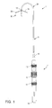
- catheter 2 generally includes a shaft 6 having a proximal end 18 and a distal end 22.
- catheter 2 includes a handle 4 secured to proximal end 18 of shaft, and a deflectable tip 28 coupled to distal end 22 of shaft 6.
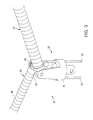
- Deflectable tip 28 comprises a movable ablation assembly 30 at its distal end that generally includes a hinge assembly 32 and a pair of arms 34, 36 that are movable between open (Fig. 3) and closed positions (Fig. 1).
- a plurality of ablation or mapping electrodes 38 see Figs.
- Handle 4 includes a tip actuation slide 10, a core wire torque ring 12 and a curvature adjustment slide 11, as well as an electrical connector 14, all described more fully below.
- Figs. 2A and 2C-2E illustrate a distal portion 31 of deflectable tip 28, and Figs. 2B and 2F-2H illustrate a proximal portion 33 of tip 28.
- the deflectable tip 28 illustrated in Figs. 2A-2H represents an exemplary embodiment, and the present invention is not limited to this configuration. That is, the ablation assemblies described below may be used with a wide variety of different tips and catheters.
- shaft 6 includes an axial lumen 48 between its proximal and distal ends 18, 22.
- shaft 6 includes a polyimide or ULTEMTM inner tube 50 surrounded by an extruded topcoat 52 of a flexible polymer such as PEBAXTM, urethane, etc.
- a braided reinforcement 54 usually stainless steel, may be embedded in topcoat 52.
- inner tube 50 includes a number of manipulator and actuator wires, fluid channels, electrical conductors and the like, extending from its proximal end to deflectable tip 28.
- Deflectable tip 28 in turn, defines at least five axial lumens extending from its proximal end to its distal end, all in communication with axial lumen 48 of inner tube 50.
- a stiffener or manipulator wire 66 for selectively adjusting the curvature of deflectable tip 28 extends through shaft 6 into tip 28 to a distal ball 67, which is mounted to an anchor member 69 near the distal end of tip 28 (see Figs. 2A and 2D, discussed in further detail below). As shown in Fig. 2D, manipulator wire 66 extends through a first axial lumen 55 in tip 28.
- the configuration of the deflectable tip 28 can be selectively adjusted to impart the desired curvature and shape to the deflectable tip as appropriate for the size and location of the area to be mapped and/or ablated.
- manipulator wire 66 when advanced into tip 28, will give tip 28 and manipulator wire 66 a combined bending stiffness greater than that of deflectable tip 28 alone, but less than the bending stiffness of shaft 6.
- second and third axial lumens 56, 57 within tip 28 receive actuator wires 58, 59 for manipulating arms 34, 36 of ablation assembly 30 (see Fig. 3).
- Actuator wires 58, 59 extend to a yoke 78 of ablation assembly 30 for manipulating the arms 34, 36, as discussed in detail below.
- actuator wires 58, 59 are joined into a single, common actuation member 61 within shaft 6 for actuation of both wires 58, 59 (and both ablation arms) substantially simultaneously.
- the actuator wires 58, 59 may remain separate through shaft 6 for independent actuation of the ablation segments.
- Deflectable tip 28 further includes a fourth axial lumen 70 through which a core wire 72 extends.
- core wire 72 forms a loop in anchor member 69 at or near distal end of tip 28 to enable rotational manipulation of tip 28.
- core wire 72 extends through shaft 6 and comprises TEFLON R -coated stainless steel. Catheters utilizing such a core wire construction are disclosed in U.S. Patent No. 5,573,533.
- tip 28 further includes a fifth, central lumen 73 for receiving electrode wires 74, thermocouple wires 76 (see Fig. 2H)) and a fluid tube 75.
- fluid tube 75 is preferably coupled to a pair of fluid conduits 85, 87 extending through tip 28 to the ablation segments for delivering fluid to each segment as discussed below.
- fluid conduits 85, 87 are bonded to fluid tube 75 with a fluid tight sheath 89 formed of a suitable material, such as a DacronTM mesh impregnated with a silicone adhesive.
- Each of electrode wires 74 is connected to one of the electrodes 38 (Fig. 3).
- wires 74 are bundled together through shaft 6 (see Fig. 2H) and then split apart into two flex circuits 77, 79 (Fig. 2F), each extending to one of the ablation segments, as discussed below.
- flex circuits 77, 79 are joined to wires 74 at a junction 81 within tip 28 having an insulating adhesive dome 83.
- the thermocouple wires 76 typically copper and constantan, extend into an aperture (not shown) in arms 34, 36, where they are anchored with high temperature adhesive.
- yoke 78 includes an annular mounting portion 91 extending into tip 28, where it is attached to anchor member 69.
- Anchor member 69 is a substantially annular member that is coupled to the outer walls of tip 28 (see Fig. 2A). As shown in Fig. 2D, anchor member 69 has a pair of cut-outs 93, 95 for receiving actuation wires 58, 59 and a number of holes for receiving manipulator wire 66, central lumen 73 and core wire 72. Core wire 72 loops around the distal end of anchor member 69 to form the core wire loop, thereby anchoring core wire 72 to tip 28. Accordingly, anchor member 69 includes two holes 97 for receiving both portions of the core wire 72 loop.
- ablation assembly 30 includes a hinge assembly 32 coupled to the distal end of deflectable tip 28, and a pair of shaft segments or arms 34, 36 pivotally mounted to hinge assembly 32.
- hinge assembly 32 includes a yoke 78, a pair of hinges 80, 82 mechanically linked to yoke 78 and a pair of actuator wires 58, 59 coupled to hinges 80, 82.
- Hinges 80, 82 preferably comprise a relatively strong metal, such as titanium, stainless steel, NitinolTM or engineering plastics, such as UltemTM.
- Actuator wires 58, 59 extend through the catheter shaft to tip actuation slide 10 (Fig. 1) of handle 4 for mechanically opening and closing arms 34, 36 (discussed below).
- Arms 34, 36 will usually be configured to move between a closed position (dotted lines in Fig. 1) substantially parallel to the longitudinal axis of shaft 6 and an open position having an included angle of about 1 to 270 degrees in the expanded position, preferably about 90 to 180 degrees and more preferably between about 120 to 175 degrees.
- This latter configuration causes a spring-like contact at the ends of the ablation arms to facilitate the application of axial force by the catheter shaft against the arms.
- the actual application of arms 34, 36 to the irregularities of the surface of the interior of the heart will probably be most extensive (and effective) with an included angle of less than 150 degrees.
- catheter shaft 6, 28 will be used to apply an axial force against arms 34, 36 to maintain continuous contact pressure against the tissue.
- catheter shaft 6, 28 can be manipulated to apply a centralized, symmetric and evenly balanced axial force against arms 34, 36, which allows a relatively long area of tissue to be engaged by two shorter segments (i.e., arms 34, 36).
- the arms 34, 36 provide increased and evenly distributed contact pressure across the entire length of the desired ablation location. Actuator wires 58, 59 close arms 34, 36 against the tissue, which enhances the contact therebetween.
- proximal movement of actuator wires 58, 59 i.e., pulling on these wires
- distal movement or pushing on wires 58, 59 will open arms 34, 36.
- arms 34, 36 may be actuated in the reverse direction.
- each arm 34, 36 will include a plurality of ablation electrodes 38 extending along the length of arms 34, 36 (note that electrodes 38 are only schematically illustrated in the drawings).
- ablation electrodes 38 are coils or solid rings that are spaced from each other along arms 34, 36 and include temperature sensors 88, such as thermocouples or thermistors.
- the electrodes 38 and temperature sensors 88 are electrically coupled to wires 74, 76 within shaft 6 by individual insulated wires 90, 92, respectively (see Fig. 12).
- they may also be electrically connected by flexible conductors (not shown), such as flex circuits, silicon matrix multi-filar ribbon cables, or the like.
- Arm segments 34, 36 will be constructed to have a desirable stiffness, depending on the application. For example, relatively stiff arm segments 34, 36 could be useful in flatter areas of the atrium, while a softer construction would be more conformable to curved (particularly convex) portions of the atrium. Softer arm constructions could be made to conform around a sharp bend in the contact surface, such as the ostium of a vein or artery or a valve annulus.
- the length of arm segments 34, 36 will also vary depending upon the number of electrodes 38 desired. Typically, each arm will include one to three electrodes 38, which results in an arm length of about 1-3cm or an overall ablation length of 2-6 cm. However, it will be readily recognizable that the arms may be longer or shorter depending on the particular procedure.
- arm segments 34, 36 may have a circular cross-section, comprising a central mandrel core 94 attached, e.g., glue, solder, weld, press-fit, or the like, at hinges 80, 82, and outer sleeves 96 extending coaxially over mandrel cores 94. Core 94 and outer sleeves 96 define an annular fluid passage 98 therebetween, which is fluidly coupled to a fluid lumen (not shown) within catheter shaft 6.
- Arms 34, 36 may include a plurality of holes along their length for directing coolant onto the target site. Alternatively, arms 34, 36 may each include a hole at their distal ends for allowing the coolant to flow through arms to convectively exchange heat with electrodes 38.
- the curvature imparted to deflectable tip 28 may be selectively adjusted by axially translating manipulator wire 66 within the catheter shaft 6.
- the curve control allows orientation of deflectable tip 28 between 0-270° of curve, more preferably between 0-180°.
- Catheter 2 may include another control wire (not shown) extending to yoke 78 for rotating ablation assembly 30 by twisting deflectable tip 28 relative to shaft 6.
- this control wire is a tapered core wire which can be rotated to cause slight twisting of the main catheter shaft 6, thereby allowing the angular orientation of the open hinge arms 34, 36 to be varied relative to shaft 6. This allows the operator to rotate the position of arms 34, 36 without physically rotating the entire catheter shaft 6, which provides for finer control of this manipulation.
- rotation of the tapered core wire causes lateral movement of the entire distal array.
- catheter 2 is transluminally, thoracoscopically (e.g., through an intercostal penetration), and/or directly delivered into the thoracic cavity so that deflectable tip 28 is positioned adjacent the heart.
- An axial force may be applied to manipulator wire 66 by sliding adjustment slide 11 to adjust the curvature of tip 28.
- deflectable tip 28 may be further positioned rotationally by rotating torque ring 42, thereby exerting torque on core wire 42 or an additional control wire (not shown) which rotates the deflectable tip about the longitudinal axis.
- actuator wires 58, 59 are moved distally to pivot arms 34, 36 about hinges 80, 82, preferably until arms 34, 36 are positioned transverse to the shaft axis.
- Catheter 2 can then be moved distally (or proximally) to engage the heart tissue at the target site with arms 34, 36.
- Catheter shaft 6 will exert an axial force against arms 34, 36, and tensioning or pulling of wires 58, 59 will enhance the contact of arms 34, 36 against the heart tissue to maintain uniform contact pressure with the tissue.
- Radiofrequency current is then delivered through connector 46 and electrode wires 74 to electrodes 38, through which current is conducted to the heart tissue to perform ablation. Mapping may also be accomplished when catheter 2 is used with an ECG.
- ablation assembly 30' includes a ball and socket rotational linkage 250 pivotally coupled to a pair of arm segments 252, 254.
- a plurality of ablation or mapping electrodes 255 are disposed on each arm segment 252, 254 as described above.
- Arms segments 252, 254 may have a semi-circular cross-sectional shape (Fig. 15), or a cylindrical shape (Figs. 16A and 16B).
- Each arm 252, 254 is movably coupled to deflectable tip 28 by a curved support wire or shaft 256, 258, respectively.
- Support wires 256, 258 extend from arms 252, 254 into slits 260 in deflectable tip 28, where they are coupled to actuator wires 58, 59 for pivoting arms 252, 254 about linkage 250.
- arms 252, 254 may be pivoted between a closed position (not shown) on either side of, and substantially parallel to, tip 28, and an open position (Fig. 15) transverse to tip 28. In the open position, support wires 256, 258 support arms to facilitate their engagement with the patient's tissue.
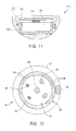
- Figs. 6-10 illustrate another embodiment of a distal ablation assembly for use with catheter 2 according to the present invention.
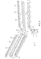
- ablation assembly 100 includes first and second arm segments 108, 110 pivotally coupled to a central hinge member 102.
- central hinge member 102 includes a pair of longitudinal support members 109, 111 each having an integral hinge 116, 118.
- Support members 109, 111 can be designed (as shown) with a recess or plenum 123 for delivery of fluid under and to the electrodes 122 mounted on top (see Figs. 9 and 10).
- Mounting/cover plates 126 cover the plenum channels 123 and provide surface for mounting electrodes 122 (as shown in Fig. 9).
- Cover plates 126 may have holes for passing fluid to or through the electrodes 122 mounted thereto (not shown).
- a central line channel 125 provides a conduit for running electrical wires and/or thermocouples to the electrodes 122.
- arm segments 108, 110 have a semi-circular cross-sectional shape (see Fig. 11), and are preferably formed using a silicone liquid injection molding (LIM) technique to mold-form arm segments 108, 110 around support members 109, 111.
- ablation assembly 100 further includes a yoke 114 and a pair of actuator wires 104, 106 for pivotally coupling arms 108, 110 and support members 109, 111 to catheter shaft 6 (Fig. 1).
- Hinges 116, 118 are preferably offset from the yoke 114 axis so that hinges 116, 118 can be disposed adjacent each other (Fig. 6). Hinges 116, 118 are designed to minimize interference with the planar contact of cover plates 126 with the tissue (i.e., hinges 116, 118 do not protrude outward when arm segments 108, 110 are open).
- Arm segments 108, 110 each include a plurality of electrodes 122 disposed on cover plates 126.
- electrodes 122 have a flattened coil design (not shown) to provide a relatively flexible electrode length.
- electrodes 122 each comprise a metallic pad 124 mechanically or adhesively attached to cover plate 126 (Fig. 9), or in an alternative configuration, to an underlying flexible printed circuit 128 (Fig. 10).
- Flexible printed circuits 128 provide a reliable electrical connection from electrodes 124, around the hinge joint 102, to connection wires 74 in shaft 6 (see Figs. 2A-2C).
- flexible printed circuits 128 may include a thermocouple junction (not shown) across several layers in the circuit for providing temperature sensing. As shown in Fig.
- electrode pads 124 are preferably relatively thick (i.e., on the order of about 0.005 to 0.020 inch), and include notches 130 that provide mechanical bending points to increase flexibility of pads 124.
- electrode pads 124 may comprise a thin film on the order of about 0.0001 to 0.005 inch thick, or a flexible grid or mesh arrangement (see Figs. 18A and 18B).
- arm segments 108, 110 each include a fluid channel through recesses 123 of support members 109, 111, which are preferably made of a suitable thermoplastic material, such as ULTEMTM or metal.
- the fluid channels or recesses 123 are coupled to a fluid lumen (not shown) in catheter shaft 6 for allowing fluid coolant to exchange heat with electrodes 122 and/or to bathe the tissue at the target tissue.
- arms 108, 110 may include a plurality of holes for directing the fluid onto the target tissue, or end holes for allowing convective cooling of electrodes 122.
- Arms 108, 110 also include thermocouples 134 adjacent to electrodes 122 for providing temperature sensing.
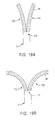
- ablation arm segments 250 preferably have a semi-circular cross-sectional shape with a relatively planar contact surface 252 on one side of the arm segment 250.
- each arm segment 250 will include a fluid plenum 132 (Fig. 18C) coupled to one of the fluid conduits 75, 73 within deflectable tip 28 for delivering fluid to the tissue at the target site.
- a flexible circuit 254 is mounted within each arm segment 250.
- Flexible circuit 254 has one or more electrodes 255 mounted on it with a plurality of openings 256 for fluidly coupling the fluid channel 132 with cavities 258 within arm segment 250.
- Recessed cavities 258 each provide an interface volume of fluid between electrodes 255 and the target site.
- recessed cavity 258 serves to distance the electrodes 255, preferably by about 0.25 to 1.5 mm, to minimize or completely prevent direct contact between the electrodes 255 and the tissue.
- the fluid delivered into cavities 258 will preferably be an ionic solution, such as isotonic saline, that conducts electrical current so as to carry the RF ablation energy from electrodes 254 to the tissue.
- an ionic solution such as isotonic saline
- the fluid interface minimizes overheating and coagulation of the blood, and damage to the tissue. This effectively eliminates the need to remove the catheter and clean the tip after a series of lesions have been formed with the ablation segments 250.
- the catheter assembly may include a single rigid tip portion with a similar construction as one of the ablation arms shown in Fig. 18A.
- the catheter may include a flexible tip portion having a plurality of longitudinally extending slots or apertures formed therethrough.
- the catheter may include an electrode or electrodes disposed within the distal tip portion of the shaft.
- the electrode may have holes aligned with the holes of the distal tip portion (which can be an insulating sheath) for allowing fluid to be delivered through the holes to create an electronically conductive fluid interface between the electrodes and the tissue.
- the fluid such as isotonic saline, passing through the openings becomes energized with sufficient RF energy supplied by the electrodes to ablate the tissue.
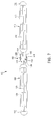
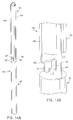
- ablation assembly 140 includes a pair of curved flexible support arms 142, 144 extending from the distal end of deflectable tip 28. Support arms 142, 144 are coupled to, or integral with, a linear ablation segment 146 that spans across support arms 142, 144.
- Linear ablation segment 146 includes first and second movable portions 148, 150 and a central thinned section 152 which is attached to an actuation wire or mandrel 154 to form the hinge point for ablation segment 146.
- Ablation segment 146 preferably includes a groove 151 extending along its proximal surface for receiving portions of support arms 142, 144.
- axial movement of wire 154 which is suitably coupled to one or both actuator wires 58, 59, causes pivoting of movable portions 148, 150 about thinned section 152.
- withdrawing wire 154 into tip 28 causes the mid-portion of ablation segment 146 to collapse toward the center until movable portions 148, 150 meet along their length in the middle (see Figs. 14A and 14B). In this manner, ablation segment 146 can be moved from a closed or delivery position (Fig.
- movable portions 148, 150 are close together and generally parallel to tip 28, and an open or expanded position (Fig. 13A), in which movable portions 148, 150 fold out to form linear ablation segment 146 having a generally planar contact surface 156 perpendicular to the shaft axis.
- a plurality of electrode pads 160 are disposed on contact surface 154 of ablation segment 146.
- electrode pads 160 and the various electrical/temperature sensor wires are snapped into ablation segment 146, which is constructed from a suitable thermoplastic material.
- the electrodes, sensors and wires may be injection molded into segment 146.
- the electrical wires extend through the curved lateral support arms 142, 144 of ablation segment 146 to deflectable tip 28 and catheter shaft 6.
- ablation segment 146 may include a fluid channel (not shown) for directing coolant fluid through segment 146 to cool electrode pads 160 and tissue at the target site.
- the fluid may exit through multiple holes (not shown) in planar surface 154, or through exit holes at the ends of movable portions 148, 150.
- the coolant acts as a heat exchanger, rather than bathing the tissue interface.
- the fluid is delivered from the catheter shaft to each ablation segment 148, 150 through the support arms 142, 144.
- Figs. 19A and 19B illustrate a modified design of the central hinge assembly illustrated in Figs. 13 and 14.
- catheter shaft 6 has a bifurcated distal end that includes a pair of arms 170, 172 extending away from each other to form a Y-shaped distal end.
- Arms 170, 172 are preferably biased away from each other into the configuration shown in Fig. 19B, i.e., with arms 170, 172 defining an included angle of about 45 to 90 degrees.
- Catheter 2 may further include a sleeve (not shown) to urge arms 170, 172 into a parallel configuration for delivery to the target site.
- Arms 170, 172 are flexible enough to allow pivoting about a central living hinge 174 at their connection point with shaft 6.
- arms 170, 172 against the heart tissue can move them into an open position, preferably defining an included angle of about 120 to 170 degrees, as shown in Fig. 19B.
- the natural biasing of arms toward the open configuration will facilitate uniform contact with the heart tissue.
- the arms would be collapsed into a parallel orientation with shaft 6 for removal by pulling back into a delivery sheath (not shown).
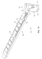
- Fig. 17 illustrates another embodiment of ablation assembly according to the present invention.
- ablation assembly 200 includes a curved support arm 204 and a manipulator member 202, such as a wire or mandrel, extending from deflectable tip 28 to a single, continuous linear ablation segment 206.
- ablation segment 206 is a continuous member that does not collapse or fold onto itself as in previous embodiments.
- a plurality of electrodes 210 are coupled to ablation segment 206 as described above. Electrodes 210 may be rings, coils, metallic pads, flattened coils, or any other suitable design.
- Ablation segment 206 is coupled to actuator wire 58 (Figs.
- deflectable tip 28 includes a longitudinal opening 208 for receiving ablation segment 206 as it rotates into the delivery position.
- proximal retraction of manipulator member 202 causes ablation segment 206 to rotate into opening 208.
- both shafts 202, 204 may withdraw segment 206 into deflectable tip 28.
- distal movement or pushing or shaft 202 causes segment 206 to rotate into the perpendicular or contact position shown in Fig. 17.
- a central, symmetric force delivered through catheter shaft 28 on segment 206 maintains a uniform continuous contact with the tissue.
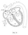
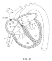
- Figs. 20, 21 and 22 illustrate exemplary methods of creating a substantially linear lesion in the left atrium of the heart according to the present invention.
- Creating a lesion in this portion of the patient's heart may be desirable, for example, in a catheter ablation procedure similar to the surgical Maze procedure for treating atrial fibrillation or flutter. This procedure typically involves ablating long linear incisions through the heart wall to electrically partition portions of the heart.
- Ablation arms 34, 36 are collapsed together for percutaneous introduction into the patients vasculature. As shown in Figs. 20 and 21, ablation arms 34, 36 are endoluminally delivered into the right atrium through the inferior vena cava, and then delivered into the left atrium through a transseptal puncture 300.
- arms 34, 36 are positioned within the left atrium, actuator wires 58, 59 are pulled (or pushed) to open arms 34, 36 as shown in Figs. 20 and 21.
- the catheter 2 can then be pushed forward into contact with tissue between the ostia of pulmonary veins (Fig. 20).
- the catheter can be retracted proximally so that the arms 34, 36 press against the septum, as shown in Fig. 21.
- the procedure shown in Fig. 21 will preferably be accomplished with circumferential electrodes, such as those shown in Figs. 3-5, or electrodes mounted to the "backside" of the ablation arms (i.e., the opposite side as that shown in Figs. 6-10 and 18).
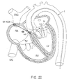
- a catheter having an ablation assembly as shown in Figs. 6-10 or 18 may be introduced retrogradely into the left atrium through the aorta via the left ventricle, and then pushed against the desired left atrial location (Fig. 22).
- Fig. 22 illustrates another method of using the present invention to make a linear lesion at the ostium of a pulmonary vein or between the pulmonary veins and mitral annulus.
- tip 28 of catheter 2 is advanced in retrograde fashion through the arterial system, across the aortic valve, and into the left atrium via the left ventricle.
- One or both arms 34, 36 are spread open by suitably manipulating actuator wires 58, 59, and the catheter is advanced so that one of the arms 34, 36 cannulates the pulmonary vein and the other arm contacts the atrial wall adjacent the mitral annulus.
- the arms 34, 36 may be retracted against the mitral annulus to create a lesion between the pulmonary vein and the mitral annulus with the backside of the electrodes. Similar to the above method, the electrodes in this embodiment will either be circumferential, or mounted to the backside of the arms.
- Figs. 23 and 24 illustrates an alternative electrode configuration for one of the ablation segments described above.
- an array of discrete block electrodes 260 are disposed on an electrode support plate 262.
- block electrodes 260 are spaced from each other, and oriented such that grooves 264 formed within the electrodes 260 extend along different directions from each other.
- annular flexible circuit traces 266 extend underneath block electrodes 260 to couple the electrodes to the connectors within the catheter shaft (not shown), as described above.
- Annular flexible circuit traces 266 preferably have an open interior space 268 to allow fluid flow through electrode blocks 260 to the tissue interface.
Abstract
Description
Radiofrequency current could then be delivered through a connector in the shaft and suitable electrode wires to the electrodes on the ablation segment(s), through which current is conducted to the heart tissue to perform ablation.
Claims (21)
- An apparatus for recording electrical signals and/or for applying energy to a target site within a patient comprising:a shaft having distal and proximal end portions and a longitudinal axis therebetween;an ablation segment at the distal end portion of the shaft defining first and second opposing ends and having one or more electrodes disposed therebetween,a connector extending through the shaft for electrically coupling the electrodes to a source of electrical energy; anda force element coupled to the shaft and disposed to apply an axially directed force to the ablation segment between the first and second opposing ends.
- The apparatus of claim 1 wherein the ablation segment is movable between a collapsed configuration sized for delivery through a percutaneous penetration in the patient and an expanded configuration, in which the ablation segment forms a substantially continuous surface transverse to the longitudinal axis of the shaft for contacting tissue at the target site.
- The apparatus of claim 2 wherein the force element is disposed to apply an axial force at a central portion of the continuous surface formed by the ablation segment.
- The apparatus of claim 1 wherein the ablation segment comprises first and second arms movable between a collapsed configuration, in which the arms are disposed close together and substantially parallel to the longitudinal axis of the shaft, and an expanded position, in which the arms are further apart and substantially perpendicular to the shaft axis.
- The apparatus of claim 4 wherein the force element comprises an actuator at the proximal end of the shaft, and one or more manipulator elements extending through the shaft from the actuator to the first and second arms.
- The apparatus of claim 5 further comprising a hinge assembly coupled to the distal end portion of the shaft for pivotally coupling the arms to the distal end portion of the shaft, the manipulator elements being coupled to the hinge assembly for pivoting the arms about the hinge assembly, and for applying an axial force to the arms in the expanded configuration to maintain contact pressure between the arms and the patient's tissue.
- The apparatus of claim 1 wherein the distal end portion of the shaft has a curvature, the apparatus further comprising an actuator coupled to the proximal end of the shaft for adjusting said curvature.
- The apparatus of claim 1 further comprising an actuator coupled to the proximal end of the shaft for rotating the ablation segment about the shaft axis.
- The apparatus of claim 2 wherein the ablation segment comprises a single substantially linear arm movable into the expanded position substantially perpendicular to the shaft axis.
- The apparatus of claim 9 wherein:the linear arm is pivotable about an axis perpendicular to the shaft axis from a first position, in which the linear arm is substantially parallel to the shaft axis, to a second position, in which the linear arm is substantially perpendicular to the shaft axis; andthe linear arm includes first and second arm segments and an integral hinge therebetween for collapsing the arm segments about the integral hinge.
- The apparatus of claim 1 wherein:the shaft comprises an inner lumen and the ablation segment comprises one or more holes fluidly coupled to the inner lumen for directing fluid through the ablation segment to exchange heat with the electrodes;the electrodes are divided into multiple segments to improve the flexibility of the electrodes along the ablation segment; andthe holes are sized and configured to direct the fluid onto the tissue at the target site to bath the tissue interface.
- The apparatus of claim 1 wherein the electrodes are raised above a surface of the ablation segment to improve contact with tissue.
- The apparatus of claim 11 wherein the electrodes are recessed into the ablation segment, the holes extending through the electrodes to direct the fluid between the electrodes and the tissue to create a fluid interface therebetween.
- The apparatus of claim 1 further comprising one or more flexible printed circuits coupling the electrodes with the connector, and one or more thermocouples integral with the flexible printed circuits, wherein the thermocouples are positioned near the electrodes, but not in direct thermal contact with the electrodes, the thermocouples being positioned at or near the tissue interface.
- A steerable electrophysiology catheter comprising:a shaft having a proximal end, a distal end and an axial lumen therebetween;first and second ablation segments at the distal end of the shaft each having a plurality of electrodes disposed therebetween,a connector extending through the shaft for electrically coupling the electrodes to a source of electrical energy; andone or more actuator elements extending through the axial lumen of the shaft from the proximal end to the distal end, the actuator elements being coupled to the ablation segments for pivoting the ablation segments into an open position transverse to the shaft axis.
- The catheter of claim 15 wherein the actuator elements are axially movable within the catheter shaft for pivoting the ablation segments between the open position and a closed position, substantially parallel to the shaft axis.
- An apparatus for applying electrical energy to a target site on a patient comprising:a shaft having distal and proximal end portions and a longitudinal axis therebetween;a substantially linear support arm disposed at the distal end portion of the shaft and having first and second ends and one or more electrodes disposed thereon, the support arm being movable to form a substantially continuous contact surface transverse to the longitudinal axis of the shaft;a connector extending through the shaft for electrically coupling the electrodes to a source of electrical energy; anda force element coupled to the shaft and disposed to apply an axial force to the support arm between the first and second ends.
- The apparatus of claim 17 wherein the linear support arm comprises first and second arm segments and an integral hinge therebetween, the first and second arm segments being pivotable about the integral hinge from a collapsed configuration, in which the arm segments are disposed together, and an expanded configuration, in which the arm segments form a substantially continuous line transverse to the shaft axis.
- The apparatus of claim 17 wherein the linear support arm is pivotable from a delivery configuration, in which the arm is substantially parallel to the shaft for endoluminal delivery to the target site, to an expanded configuration, in which the arm forms a substantially continuous line transverse to the shaft axis.
- An apparatus for recording electrical signals and/or for applying energy to a target site within a patient comprising:a shaft having distal and proximal end portions and a fluid lumen therebetween;an ablation segment at the distal end portion of the shaft comprising an outer insulating surface and one or more electrodes recessed from the outer insulating surface to form a space between the electrodes and said surface, wherein the fluid lumen is coupled to said space such that electrically conducting fluid can be delivered to the space to form a fluid interface between the electrodes and the target site; anda connector extending through the shaft for electrically coupling the electrodes to a source of electrical energy.
- The apparatus of claim 20 wherein:the ablation segment comprises an insulating arm defining a fluid plenum coupled to the fluid lumen within the shaft; andthe electrodes are mounted to a substantially planar flexible circuit having a plurality of openings coupled to the fluid plenum, wherein the planar flexible circuit is recessed from an outer surface of the arm to form a fluid cavity between the tissue and the electrodes.
Priority Applications (1)
| Application Number | Priority Date | Filing Date | Title |
|---|---|---|---|
| EP20060012614 EP1707150B1 (en) | 1997-02-04 | 1998-01-23 | System for tissue mapping and ablation |
Applications Claiming Priority (2)
| Application Number | Priority Date | Filing Date | Title |
|---|---|---|---|
| US794804 | 1997-02-04 | ||
| US08/794,804 US5916213A (en) | 1997-02-04 | 1997-02-04 | Systems and methods for tissue mapping and ablation |
Related Child Applications (1)
| Application Number | Title | Priority Date | Filing Date |
|---|---|---|---|
| EP20060012614 Division EP1707150B1 (en) | 1997-02-04 | 1998-01-23 | System for tissue mapping and ablation |
Publications (3)
| Publication Number | Publication Date |
|---|---|
| EP0856291A2 true EP0856291A2 (en) | 1998-08-05 |
| EP0856291A3 EP0856291A3 (en) | 1998-12-02 |
| EP0856291B1 EP0856291B1 (en) | 2006-06-21 |
Family
ID=25163730
Family Applications (2)
| Application Number | Title | Priority Date | Filing Date |
|---|---|---|---|
| EP20060012614 Expired - Lifetime EP1707150B1 (en) | 1997-02-04 | 1998-01-23 | System for tissue mapping and ablation |
| EP98300478A Expired - Lifetime EP0856291B1 (en) | 1997-02-04 | 1998-01-23 | System for tissue mapping and ablation |
Family Applications Before (1)
| Application Number | Title | Priority Date | Filing Date |
|---|---|---|---|
| EP20060012614 Expired - Lifetime EP1707150B1 (en) | 1997-02-04 | 1998-01-23 | System for tissue mapping and ablation |
Country Status (4)
| Country | Link |
|---|---|
| US (2) | US5916213A (en) |
| EP (2) | EP1707150B1 (en) |
| JP (1) | JPH10290806A (en) |
| DE (1) | DE69834967T2 (en) |
Cited By (16)
| Publication number | Priority date | Publication date | Assignee | Title |
|---|---|---|---|---|
| WO2000029062A2 (en) * | 1998-11-12 | 2000-05-25 | Boston Scientific Limited | Method of manufacturing cellulosic structures, and electrode assembly comprising an expandable-collapsible body |
| EP1199997A1 (en) * | 1999-07-07 | 2002-05-02 | The Uab Research Foundation | Ablation tool for forming lesions in body tissue |
| EP1281366A3 (en) * | 1999-06-23 | 2003-03-19 | Novasys Medical, Inc. | Treatment of sphincters with electrosurgery and active substances |
| WO2004028386A1 (en) * | 2002-09-24 | 2004-04-08 | Scimed Life Systems, Inc. | Electrophysiology electrode having multiple power connections and electrophysiology devices including the same |
| WO2005060852A1 (en) * | 2003-12-02 | 2005-07-07 | Scimed Life Systems, Inc. | Clamp based apparatus for forming lesions in tissue and confirming whether a therapeutic lesion has been formed |
| US7357800B2 (en) | 2003-02-14 | 2008-04-15 | Boston Scientific Scimed, Inc. | Power supply and control apparatus and electrophysiology systems including the same |
| US7549988B2 (en) | 2004-08-30 | 2009-06-23 | Boston Scientific Scimed, Inc. | Hybrid lesion formation apparatus, systems and methods |
| US7727231B2 (en) | 2005-01-08 | 2010-06-01 | Boston Scientific Scimed, Inc. | Apparatus and methods for forming lesions in tissue and applying stimulation energy to tissue in which lesions are formed |
| US7785324B2 (en) | 2005-02-25 | 2010-08-31 | Endoscopic Technologies, Inc. (Estech) | Clamp based lesion formation apparatus and methods configured to protect non-target tissue |
| US8391947B2 (en) | 2010-12-30 | 2013-03-05 | Biosense Webster (Israel), Ltd. | Catheter with sheet array of electrodes |
| US8585701B2 (en) | 2002-02-19 | 2013-11-19 | Estech, Inc. (Endoscopic Technologies, Inc.) | Apparatus for securing an electrophysiology probe to a clamp |
| US8945151B2 (en) | 2005-07-13 | 2015-02-03 | Atricure, Inc. | Surgical clip applicator and apparatus including the same |
| CN106264715A (en) * | 2015-06-29 | 2017-01-04 | 韦伯斯特生物官能(以色列)有限公司 | There is the conduit of closed loop array with plane internal linear electrode part |
| US11039772B2 (en) | 2015-06-29 | 2021-06-22 | Biosense Webster (Israel) Ltd. | Catheter with stacked spine electrode assembly |
| US11083400B2 (en) | 2014-11-20 | 2021-08-10 | Biosense Webster (Israel) Ltd. | Catheter with high density electrode spine array |
| US11116436B2 (en) | 2015-06-30 | 2021-09-14 | Biosense Webster (Israel) Ltd. | Catheter having closed electrode assembly with spines of uniform length |
Families Citing this family (658)
| Publication number | Priority date | Publication date | Assignee | Title |
|---|---|---|---|---|
| US6161543A (en) | 1993-02-22 | 2000-12-19 | Epicor, Inc. | Methods of epicardial ablation for creating a lesion around the pulmonary veins |
| US6277116B1 (en) * | 1994-05-06 | 2001-08-21 | Vidaderm | Systems and methods for shrinking collagen in the dermis |
| US6071274A (en) | 1996-12-19 | 2000-06-06 | Ep Technologies, Inc. | Loop structures for supporting multiple electrode elements |
| US5814029A (en) * | 1994-11-03 | 1998-09-29 | Daig Corporation | Guiding introducer system for use in ablation and mapping procedures in the left ventricle |
| US5897553A (en) | 1995-11-02 | 1999-04-27 | Medtronic, Inc. | Ball point fluid-assisted electrocautery device |
| US6409722B1 (en) | 1998-07-07 | 2002-06-25 | Medtronic, Inc. | Apparatus and method for creating, maintaining, and controlling a virtual electrode used for the ablation of tissue |
| US7384423B1 (en) | 1995-07-13 | 2008-06-10 | Origin Medsystems, Inc. | Tissue dissection method |
| US6805128B1 (en) | 1996-10-22 | 2004-10-19 | Epicor Medical, Inc. | Apparatus and method for ablating tissue |
| US6840936B2 (en) * | 1996-10-22 | 2005-01-11 | Epicor Medical, Inc. | Methods and devices for ablation |
| US6311692B1 (en) | 1996-10-22 | 2001-11-06 | Epicor, Inc. | Apparatus and method for diagnosis and therapy of electrophysiological disease |
| US20040260278A1 (en) * | 1996-10-22 | 2004-12-23 | Anderson Scott C. | Apparatus and method for ablating tissue |
| US7052493B2 (en) | 1996-10-22 | 2006-05-30 | Epicor Medical, Inc. | Methods and devices for ablation |
| US6719755B2 (en) * | 1996-10-22 | 2004-04-13 | Epicor Medical, Inc. | Methods and devices for ablation |
| US6071279A (en) * | 1996-12-19 | 2000-06-06 | Ep Technologies, Inc. | Branched structures for supporting multiple electrode elements |
| US6024740A (en) * | 1997-07-08 | 2000-02-15 | The Regents Of The University Of California | Circumferential ablation device assembly |
| US5938660A (en) * | 1997-06-27 | 1999-08-17 | Daig Corporation | Process and device for the treatment of atrial arrhythmia |
| US6251109B1 (en) * | 1997-06-27 | 2001-06-26 | Daig Corporation | Process and device for the treatment of atrial arrhythmia |
| US6096037A (en) | 1997-07-29 | 2000-08-01 | Medtronic, Inc. | Tissue sealing electrosurgery device and methods of sealing tissue |
| AUPO820897A0 (en) * | 1997-07-24 | 1997-08-14 | Cardiac Crc Nominees Pty Limited | An intraoperative endocardial and epicardial ablation probe |
| FR2768324B1 (en) | 1997-09-12 | 1999-12-10 | Jacques Seguin | SURGICAL INSTRUMENT FOR PERCUTANEOUSLY FIXING TWO AREAS OF SOFT TISSUE, NORMALLY MUTUALLY REMOTE, TO ONE ANOTHER |
| US6610055B1 (en) | 1997-10-10 | 2003-08-26 | Scimed Life Systems, Inc. | Surgical method for positioning a diagnostic or therapeutic element on the epicardium or other organ surface |
| US8709007B2 (en) | 1997-10-15 | 2014-04-29 | St. Jude Medical, Atrial Fibrillation Division, Inc. | Devices and methods for ablating cardiac tissue |
| US6319241B1 (en) * | 1998-04-30 | 2001-11-20 | Medtronic, Inc. | Techniques for positioning therapy delivery elements within a spinal cord or a brain |
| US7326178B1 (en) | 1998-06-22 | 2008-02-05 | Origin Medsystems, Inc. | Vessel retraction device and method |
| US6976957B1 (en) | 1998-06-22 | 2005-12-20 | Origin Medsystems, Inc. | Cannula-based surgical instrument and method |
| US6830546B1 (en) | 1998-06-22 | 2004-12-14 | Origin Medsystems, Inc. | Device and method for remote vessel ligation |
| US6066132A (en) * | 1998-06-30 | 2000-05-23 | Ethicon, Inc. | Articulating endometrial ablation device |
| US6537248B2 (en) | 1998-07-07 | 2003-03-25 | Medtronic, Inc. | Helical needle apparatus for creating a virtual electrode used for the ablation of tissue |
| US6706039B2 (en) | 1998-07-07 | 2004-03-16 | Medtronic, Inc. | Method and apparatus for creating a bi-polar virtual electrode used for the ablation of tissue |
| EP0979635A2 (en) | 1998-08-12 | 2000-02-16 | Origin Medsystems, Inc. | Tissue dissector apparatus |
| US8308719B2 (en) | 1998-09-21 | 2012-11-13 | St. Jude Medical, Atrial Fibrillation Division, Inc. | Apparatus and method for ablating tissue |
| US7481803B2 (en) * | 2000-11-28 | 2009-01-27 | Flowmedica, Inc. | Intra-aortic renal drug delivery catheter |
| US6749598B1 (en) * | 1999-01-11 | 2004-06-15 | Flowmedica, Inc. | Apparatus and methods for treating congestive heart disease |
| US7329236B2 (en) * | 1999-01-11 | 2008-02-12 | Flowmedica, Inc. | Intra-aortic renal drug delivery catheter |
| US7780628B1 (en) | 1999-01-11 | 2010-08-24 | Angiodynamics, Inc. | Apparatus and methods for treating congestive heart disease |
| US8216256B2 (en) | 1999-04-09 | 2012-07-10 | Evalve, Inc. | Detachment mechanism for implantable fixation devices |
| DE60045429D1 (en) | 1999-04-09 | 2011-02-03 | Evalve Inc | Device for heart valve surgery |
| US20040044350A1 (en) | 1999-04-09 | 2004-03-04 | Evalve, Inc. | Steerable access sheath and methods of use |
| US6752813B2 (en) | 1999-04-09 | 2004-06-22 | Evalve, Inc. | Methods and devices for capturing and fixing leaflets in valve repair |
| US7811296B2 (en) | 1999-04-09 | 2010-10-12 | Evalve, Inc. | Fixation devices for variation in engagement of tissue |
| US7666204B2 (en) | 1999-04-09 | 2010-02-23 | Evalve, Inc. | Multi-catheter steerable guiding system and methods of use |
| US8285393B2 (en) * | 1999-04-16 | 2012-10-09 | Laufer Michael D | Device for shaping infarcted heart tissue and method of using the device |
| US6216045B1 (en) | 1999-04-26 | 2001-04-10 | Advanced Neuromodulation Systems, Inc. | Implantable lead and method of manufacture |
| EP1207788A4 (en) | 1999-07-19 | 2009-12-09 | St Jude Medical Atrial Fibrill | Apparatus and method for ablating tissue |
| US20070282324A1 (en) * | 1999-07-19 | 2007-12-06 | Matthias Vaska | Apparatus and method for diagnosis and therapy of electrophysiological disease |
| US6852120B1 (en) | 1999-08-10 | 2005-02-08 | Biosense Webster, Inc | Irrigation probe for ablation during open heart surgery |
| US6332881B1 (en) | 1999-09-01 | 2001-12-25 | Cardima, Inc. | Surgical ablation tool |
| US6306133B1 (en) | 1999-10-02 | 2001-10-23 | Quantum Cor Incorporated | Ablation catheter system and methods for repairing a valvular annulus |
| US20060095032A1 (en) | 1999-11-16 | 2006-05-04 | Jerome Jackson | Methods and systems for determining physiologic characteristics for treatment of the esophagus |
| CA2825425C (en) | 1999-11-16 | 2016-03-22 | Covidien Lp | System and method of treating abnormal tissue in the human esophagus |
| US20040215235A1 (en) | 1999-11-16 | 2004-10-28 | Barrx, Inc. | Methods and systems for determining physiologic characteristics for treatment of the esophagus |
| US6542781B1 (en) | 1999-11-22 | 2003-04-01 | Scimed Life Systems, Inc. | Loop structures for supporting diagnostic and therapeutic elements in contact with body tissue |
| US8241274B2 (en) | 2000-01-19 | 2012-08-14 | Medtronic, Inc. | Method for guiding a medical device |
| US8221402B2 (en) | 2000-01-19 | 2012-07-17 | Medtronic, Inc. | Method for guiding a medical device |
| US7706882B2 (en) | 2000-01-19 | 2010-04-27 | Medtronic, Inc. | Methods of using high intensity focused ultrasound to form an ablated tissue area |
| US6663622B1 (en) * | 2000-02-11 | 2003-12-16 | Iotek, Inc. | Surgical devices and methods for use in tissue ablation procedures |
| US6497703B1 (en) * | 2000-03-02 | 2002-12-24 | Biosense Webster | Cryoablation catheter for long lesion ablations |
| US8048070B2 (en) | 2000-03-06 | 2011-11-01 | Salient Surgical Technologies, Inc. | Fluid-assisted medical devices, systems and methods |
| US8083736B2 (en) | 2000-03-06 | 2011-12-27 | Salient Surgical Technologies, Inc. | Fluid-assisted medical devices, systems and methods |
| US6468203B2 (en) | 2000-04-03 | 2002-10-22 | Neoguide Systems, Inc. | Steerable endoscope and improved method of insertion |
| US8888688B2 (en) | 2000-04-03 | 2014-11-18 | Intuitive Surgical Operations, Inc. | Connector device for a controllable instrument |
| US8517923B2 (en) | 2000-04-03 | 2013-08-27 | Intuitive Surgical Operations, Inc. | Apparatus and methods for facilitating treatment of tissue via improved delivery of energy based and non-energy based modalities |
| US6610007B2 (en) | 2000-04-03 | 2003-08-26 | Neoguide Systems, Inc. | Steerable segmented endoscope and method of insertion |
| US6514250B1 (en) | 2000-04-27 | 2003-02-04 | Medtronic, Inc. | Suction stabilized epicardial ablation devices |
| EP1278471B1 (en) | 2000-04-27 | 2005-06-15 | Medtronic, Inc. | Vibration sensitive ablation apparatus |
| US6558382B2 (en) * | 2000-04-27 | 2003-05-06 | Medtronic, Inc. | Suction stabilized epicardial ablation devices |
| JP4926359B2 (en) | 2000-05-03 | 2012-05-09 | シー・アール・バード・インコーポレーテッド | Apparatus and method for mapping and cauterization in electrophysiological procedures |
| EP2275174B1 (en) | 2000-07-13 | 2016-04-20 | ReCor Medical, Inc. | Thermal treatment apparatus with ultrasound energy application |
| CA2415671C (en) * | 2000-07-13 | 2011-02-01 | Transurgical, Inc. | Energy application with inflatable annular lens |
| US6746446B1 (en) | 2000-08-04 | 2004-06-08 | Cardima, Inc. | Electrophysiological device for the isthmus |
| US6669692B1 (en) * | 2000-08-21 | 2003-12-30 | Biosense Webster, Inc. | Ablation catheter with cooled linear electrode |
| US6926669B1 (en) | 2000-10-10 | 2005-08-09 | Medtronic, Inc. | Heart wall ablation/mapping catheter and method |
| US6475179B1 (en) * | 2000-11-10 | 2002-11-05 | New England Medical Center | Tissue folding device for tissue ablation, and method thereof |
| US6558313B1 (en) | 2000-11-17 | 2003-05-06 | Embro Corporation | Vein harvesting system and method |
| US7047068B2 (en) * | 2000-12-11 | 2006-05-16 | C.R. Bard, Inc. | Microelectrode catheter for mapping and ablation |
| US20040138621A1 (en) | 2003-01-14 | 2004-07-15 | Jahns Scott E. | Devices and methods for interstitial injection of biologic agents into tissue |
| US7740623B2 (en) | 2001-01-13 | 2010-06-22 | Medtronic, Inc. | Devices and methods for interstitial injection of biologic agents into tissue |
| US6648883B2 (en) | 2001-04-26 | 2003-11-18 | Medtronic, Inc. | Ablation system and method of use |
| US6663627B2 (en) * | 2001-04-26 | 2003-12-16 | Medtronic, Inc. | Ablation system and method of use |
| US6807968B2 (en) | 2001-04-26 | 2004-10-26 | Medtronic, Inc. | Method and system for treatment of atrial tachyarrhythmias |
| US7250048B2 (en) | 2001-04-26 | 2007-07-31 | Medtronic, Inc. | Ablation system and method of use |
| US7959626B2 (en) | 2001-04-26 | 2011-06-14 | Medtronic, Inc. | Transmural ablation systems and methods |
| US6989010B2 (en) * | 2001-04-26 | 2006-01-24 | Medtronic, Inc. | Ablation system and method of use |
| US6699240B2 (en) * | 2001-04-26 | 2004-03-02 | Medtronic, Inc. | Method and apparatus for tissue ablation |
| EP1383426B1 (en) * | 2001-04-27 | 2008-12-24 | C.R. Bard, Inc. | Catheter for three dimensional mapping of electrical activity in blood vessels |
| US7727229B2 (en) * | 2001-05-01 | 2010-06-01 | C.R. Bard, Inc. | Method and apparatus for altering conduction properties in the heart and in adjacent vessels |
| US10835307B2 (en) | 2001-06-12 | 2020-11-17 | Ethicon Llc | Modular battery powered handheld surgical instrument containing elongated multi-layered shaft |
| US6652518B2 (en) * | 2001-09-28 | 2003-11-25 | Ethicon, Inc. | Transmural ablation tool and method |
| US6955640B2 (en) * | 2001-09-28 | 2005-10-18 | Cardiac Pacemakers, Inc. | Brachytherapy for arrhythmias |
| US6669693B2 (en) * | 2001-11-13 | 2003-12-30 | Mayo Foundation For Medical Education And Research | Tissue ablation device and methods of using |
| US6575971B2 (en) * | 2001-11-15 | 2003-06-10 | Quantum Cor, Inc. | Cardiac valve leaflet stapler device and methods thereof |
| US20040092806A1 (en) * | 2001-12-11 | 2004-05-13 | Sagon Stephen W | Microelectrode catheter for mapping and ablation |
| US6961602B2 (en) | 2001-12-31 | 2005-11-01 | Biosense Webster, Inc. | Catheter having multiple spines each having electrical mapping and location sensing capabilities |
| US7967816B2 (en) | 2002-01-25 | 2011-06-28 | Medtronic, Inc. | Fluid-assisted electrosurgical instrument with shapeable electrode |
| US20070293855A1 (en) * | 2002-02-15 | 2007-12-20 | Sliwa John W Jr | Methods and devices for ablation |
| US7048754B2 (en) | 2002-03-01 | 2006-05-23 | Evalve, Inc. | Suture fasteners and methods of use |
| US7118566B2 (en) | 2002-05-16 | 2006-10-10 | Medtronic, Inc. | Device and method for needle-less interstitial injection of fluid for ablation of cardiac tissue |
| US7294143B2 (en) | 2002-05-16 | 2007-11-13 | Medtronic, Inc. | Device and method for ablation of cardiac tissue |
| US6855140B2 (en) * | 2002-06-06 | 2005-02-15 | Thomas E. Albrecht | Method of tissue lesion removal |
| US6929642B2 (en) * | 2002-06-28 | 2005-08-16 | Ethicon, Inc. | RF device for treating the uterus |
| US20040002702A1 (en) * | 2002-06-28 | 2004-01-01 | Ethicon, Inc. | RF device for treating the uterus |
| US20040082859A1 (en) | 2002-07-01 | 2004-04-29 | Alan Schaer | Method and apparatus employing ultrasound energy to treat body sphincters |
| US7089045B2 (en) * | 2002-08-30 | 2006-08-08 | Biosense Webster, Inc. | Catheter and method for mapping Purkinje fibers |
| EP1585572A4 (en) | 2002-09-20 | 2010-02-24 | Flowmedica Inc | Method and apparatus for intra aortic substance delivery to a branch vessel |
| US7063679B2 (en) * | 2002-09-20 | 2006-06-20 | Flowmedica, Inc. | Intra-aortic renal delivery catheter |
| EP1539291A4 (en) * | 2002-09-20 | 2010-03-10 | Flowmedica Inc | Method and apparatus for selective material delivery via an intra-renal catheter |
| US7993325B2 (en) | 2002-09-20 | 2011-08-09 | Angio Dynamics, Inc. | Renal infusion systems and methods |
| EP1624909A2 (en) * | 2002-09-20 | 2006-02-15 | FlowMedica, Inc. | Appartus and method for inserting an intra-aorta catheter trough a delivery sheath |
| US9956377B2 (en) * | 2002-09-20 | 2018-05-01 | Angiodynamics, Inc. | Method and apparatus for intra-aortic substance delivery to a branch vessel |
| US8613744B2 (en) | 2002-09-30 | 2013-12-24 | Relievant Medsystems, Inc. | Systems and methods for navigating an instrument through bone |
| US8361067B2 (en) | 2002-09-30 | 2013-01-29 | Relievant Medsystems, Inc. | Methods of therapeutically heating a vertebral body to treat back pain |
| US8808284B2 (en) | 2008-09-26 | 2014-08-19 | Relievant Medsystems, Inc. | Systems for navigating an instrument through bone |
| US7101367B2 (en) | 2002-09-30 | 2006-09-05 | Ethicon, Inc. | Deployable cryosurgical catheter |
| US6907884B2 (en) | 2002-09-30 | 2005-06-21 | Depay Acromed, Inc. | Method of straddling an intraosseous nerve |
| US7258690B2 (en) | 2003-03-28 | 2007-08-21 | Relievant Medsystems, Inc. | Windowed thermal ablation probe |
| US7087064B1 (en) * | 2002-10-15 | 2006-08-08 | Advanced Cardiovascular Systems, Inc. | Apparatuses and methods for heart valve repair |
| US20050033137A1 (en) * | 2002-10-25 | 2005-02-10 | The Regents Of The University Of Michigan | Ablation catheters and methods for their use |
| US20040082947A1 (en) * | 2002-10-25 | 2004-04-29 | The Regents Of The University Of Michigan | Ablation catheters |
| US7027851B2 (en) * | 2002-10-30 | 2006-04-11 | Biosense Webster, Inc. | Multi-tip steerable catheter |
| US7083620B2 (en) | 2002-10-30 | 2006-08-01 | Medtronic, Inc. | Electrosurgical hemostat |
| US7981152B1 (en) | 2004-12-10 | 2011-07-19 | Advanced Cardiovascular Systems, Inc. | Vascular delivery system for accessing and delivering devices into coronary sinus and other vascular sites |
| US7335213B1 (en) | 2002-11-15 | 2008-02-26 | Abbott Cardiovascular Systems Inc. | Apparatus and methods for heart valve repair |
| US9149602B2 (en) | 2005-04-22 | 2015-10-06 | Advanced Cardiovascular Systems, Inc. | Dual needle delivery system |
| US7485143B2 (en) * | 2002-11-15 | 2009-02-03 | Abbott Cardiovascular Systems Inc. | Apparatuses and methods for heart valve repair |
| US7404824B1 (en) | 2002-11-15 | 2008-07-29 | Advanced Cardiovascular Systems, Inc. | Valve aptation assist device |
| US7331972B1 (en) | 2002-11-15 | 2008-02-19 | Abbott Cardiovascular Systems Inc. | Heart valve chord cutter |
| US8187324B2 (en) | 2002-11-15 | 2012-05-29 | Advanced Cardiovascular Systems, Inc. | Telescoping apparatus for delivering and adjusting a medical device in a vessel |
| US6984232B2 (en) | 2003-01-17 | 2006-01-10 | St. Jude Medical, Daig Division, Inc. | Ablation catheter assembly having a virtual electrode comprising portholes |
| US7387629B2 (en) | 2003-01-21 | 2008-06-17 | St. Jude Medical, Atrial Fibrillation Division, Inc. | Catheter design that facilitates positioning at tissue to be diagnosed or treated |
| US7819866B2 (en) | 2003-01-21 | 2010-10-26 | St. Jude Medical, Atrial Fibrillation Division, Inc. | Ablation catheter and electrode |
| US6960207B2 (en) * | 2003-01-21 | 2005-11-01 | St Jude Medical, Daig Division, Inc. | Ablation catheter having a virtual electrode comprising portholes and a porous conductor |
| EP1596742B1 (en) * | 2003-01-31 | 2008-03-05 | Smith & Nephew, Inc. | Cartilage treatment probe |
| US8066700B2 (en) * | 2003-01-31 | 2011-11-29 | Smith & Nephew, Inc. | Cartilage treatment probe |
| US7837676B2 (en) * | 2003-02-20 | 2010-11-23 | Recor Medical, Inc. | Cardiac ablation devices |
| ES2417815T3 (en) * | 2003-03-28 | 2013-08-09 | C. R. Bard, Inc. | Braided mesh catheter |
| US7497857B2 (en) | 2003-04-29 | 2009-03-03 | Medtronic, Inc. | Endocardial dispersive electrode for use with a monopolar RF ablation pen |
| US10667823B2 (en) | 2003-05-19 | 2020-06-02 | Evalve, Inc. | Fixation devices, systems and methods for engaging tissue |
| US7818048B2 (en) | 2003-06-02 | 2010-10-19 | Biosense Webster, Inc. | Catheter and method for mapping a pulmonary vein |
| US7003342B2 (en) * | 2003-06-02 | 2006-02-21 | Biosense Webster, Inc. | Catheter and method for mapping a pulmonary vein |
| EP1635736A2 (en) * | 2003-06-05 | 2006-03-22 | FlowMedica, Inc. | Systems and methods for performing bi-lateral interventions or diagnosis in branched body lumens |
| MXPA05013310A (en) | 2003-06-10 | 2006-05-19 | Neomedix Corp | Device and methods useable for treatment of glaucoma and other surgical procedures. |
| JP4611309B2 (en) | 2003-06-10 | 2011-01-12 | ネオメディックス コーポレイション | Tubular resection device and method for cutting tissue pieces from a patient's body |
| CA2528056C (en) * | 2003-06-10 | 2014-07-29 | Neomedix Corporation | Electrosurgical devices and methods for selective cutting of tissue |
| US20060167437A1 (en) * | 2003-06-17 | 2006-07-27 | Flowmedica, Inc. | Method and apparatus for intra aortic substance delivery to a branch vessel |
| US7101362B2 (en) * | 2003-07-02 | 2006-09-05 | St. Jude Medical, Atrial Fibrillation Division, Inc. | Steerable and shapable catheter employing fluid force |
| US7789877B2 (en) | 2003-07-02 | 2010-09-07 | St. Jude Medical, Atrial Fibrillation Division, Inc. | Ablation catheter electrode arrangement |
| US7235070B2 (en) * | 2003-07-02 | 2007-06-26 | St. Jude Medical, Atrial Fibrillation Division, Inc. | Ablation fluid manifold for ablation catheter |
| US6973339B2 (en) * | 2003-07-29 | 2005-12-06 | Biosense, Inc | Lasso for pulmonary vein mapping and ablation |
| EP1659970A4 (en) * | 2003-08-05 | 2008-05-21 | Flowmedica Inc | Sytem and method for prevention of radiocontrast induced nephropathy |
| US20050059448A1 (en) * | 2003-09-11 | 2005-03-17 | Scott Sims | Method and apparatus for playing card game |
| US7438714B2 (en) * | 2003-09-12 | 2008-10-21 | Boston Scientific Scimed, Inc. | Vacuum-based catheter stabilizer |
| US7234225B2 (en) * | 2003-09-22 | 2007-06-26 | St. Jude Medical, Atrial Fibrillation Division, Inc. | Method for manufacturing medical device having embedded traces and formed electrodes |
| US7229437B2 (en) * | 2003-09-22 | 2007-06-12 | St. Jude Medical, Atrial Fibrillation Division, Inc. | Medical device having integral traces and formed electrodes |
| US20050065509A1 (en) * | 2003-09-22 | 2005-03-24 | Scimed Life Systems, Inc. | Flat electrode arrays for generating flat lesions |
| US8147486B2 (en) * | 2003-09-22 | 2012-04-03 | St. Jude Medical, Atrial Fibrillation Division, Inc. | Medical device with flexible printed circuit |
| US7998112B2 (en) * | 2003-09-30 | 2011-08-16 | Abbott Cardiovascular Systems Inc. | Deflectable catheter assembly and method of making same |
| JP4455002B2 (en) * | 2003-10-06 | 2010-04-21 | オリンパス株式会社 | High frequency knife |
| US7155270B2 (en) * | 2003-10-24 | 2006-12-26 | Biosense Webster, Inc. | Catheter with multi-spine mapping assembly |
| US7238180B2 (en) * | 2003-10-30 | 2007-07-03 | Medicalcv Inc. | Guided ablation with end-fire fiber |
| US7232437B2 (en) * | 2003-10-30 | 2007-06-19 | Medical Cv, Inc. | Assessment of lesion transmurality |
| US7238179B2 (en) * | 2003-10-30 | 2007-07-03 | Medical Cv, Inc. | Apparatus and method for guided ablation treatment |
| WO2005044124A1 (en) | 2003-10-30 | 2005-05-19 | Medical Cv, Inc. | Apparatus and method for laser treatment |
| US7150745B2 (en) | 2004-01-09 | 2006-12-19 | Barrx Medical, Inc. | Devices and methods for treatment of luminal tissue |
| US8182501B2 (en) | 2004-02-27 | 2012-05-22 | Ethicon Endo-Surgery, Inc. | Ultrasonic surgical shears and method for sealing a blood vessel using same |
| WO2005091910A2 (en) * | 2004-03-04 | 2005-10-06 | Flowmedica, Inc. | Sheath for use in peripheral interventions |
| AU2005231443B2 (en) | 2004-04-01 | 2012-02-23 | The General Hospital Corporation | Method and apparatus for dermatological treatment and tissue reshaping |
| US7803150B2 (en) | 2004-04-21 | 2010-09-28 | Acclarent, Inc. | Devices, systems and methods useable for treating sinusitis |
| US7654997B2 (en) | 2004-04-21 | 2010-02-02 | Acclarent, Inc. | Devices, systems and methods for diagnosing and treating sinusitus and other disorders of the ears, nose and/or throat |
| US20190314620A1 (en) | 2004-04-21 | 2019-10-17 | Acclarent, Inc. | Apparatus and methods for dilating and modifying ostia of paranasal sinuses and other intranasal or paranasal structures |
| US10188413B1 (en) | 2004-04-21 | 2019-01-29 | Acclarent, Inc. | Deflectable guide catheters and related methods |
| US8702626B1 (en) | 2004-04-21 | 2014-04-22 | Acclarent, Inc. | Guidewires for performing image guided procedures |
| US20070167682A1 (en) | 2004-04-21 | 2007-07-19 | Acclarent, Inc. | Endoscopic methods and devices for transnasal procedures |
| US9399121B2 (en) | 2004-04-21 | 2016-07-26 | Acclarent, Inc. | Systems and methods for transnasal dilation of passageways in the ear, nose or throat |
| US8747389B2 (en) | 2004-04-21 | 2014-06-10 | Acclarent, Inc. | Systems for treating disorders of the ear, nose and throat |
| US20060063973A1 (en) | 2004-04-21 | 2006-03-23 | Acclarent, Inc. | Methods and apparatus for treating disorders of the ear, nose and throat |
| US7291142B2 (en) * | 2004-05-10 | 2007-11-06 | Boston Scientific Scimed, Inc. | Low temperature lesion formation apparatus, systems and methods |
| US7288088B2 (en) * | 2004-05-10 | 2007-10-30 | Boston Scientific Scimed, Inc. | Clamp based low temperature lesion formation apparatus, systems and methods |
| US7582083B2 (en) * | 2004-05-10 | 2009-09-01 | Boston Scientific Scimed, Inc. | Probe based low temperature lesion formation apparatus, systems and methods |
| US8333764B2 (en) | 2004-05-12 | 2012-12-18 | Medtronic, Inc. | Device and method for determining tissue thickness and creating cardiac ablation lesions |
| JP2007537298A (en) * | 2004-05-14 | 2007-12-20 | フロウメディカ, インコーポレイテッド | Bilateral local renal delivery for the treatment of congestive heart failure and BNP therapy |
| AU2005244903B2 (en) | 2004-05-14 | 2010-11-04 | Evalve, Inc. | Locking mechanisms for fixation devices and methods of engaging tissue |
| ES2308505T3 (en) | 2004-05-14 | 2008-12-01 | Medtronic, Inc. | ULTRASONIC ENERGY USE SYSTEM FOCUSED ON HIGH INTENS IDAD TO FORM A CUTTED FABRIC AREA. |
| US8249685B2 (en) | 2004-05-17 | 2012-08-21 | C.R. Bard, Inc. | Method and apparatus for mapping and/or ablation of cardiac tissue |
| US7276064B2 (en) * | 2004-05-27 | 2007-10-02 | St. Jude Medical, Atrial Fibrillation Division, Inc. | Side-port sheath for catheter placement and translation |
| US7087053B2 (en) * | 2004-05-27 | 2006-08-08 | St. Jude Medical, Atrial Fibrillation Division, Inc. | Catheter with bifurcated, collapsible tip for sensing and ablating |
| US20050273096A1 (en) * | 2004-05-27 | 2005-12-08 | Roop John A | Anchoring introducer sheath with distal slots for catheter delivery and translation |
| WO2005120376A2 (en) | 2004-06-02 | 2005-12-22 | Medtronic, Inc. | Ablation device with jaws |
| WO2005120375A2 (en) | 2004-06-02 | 2005-12-22 | Medtronic, Inc. | Loop ablation apparatus and method |
| ATE516762T1 (en) | 2004-06-02 | 2011-08-15 | Medtronic Inc | ABLATION AND STAPLE INSTRUMENT |
| WO2005120374A1 (en) | 2004-06-02 | 2005-12-22 | Medtronic, Inc. | Compound bipolar ablation device and method |
| US8663245B2 (en) | 2004-06-18 | 2014-03-04 | Medtronic, Inc. | Device for occlusion of a left atrial appendage |
| US8926635B2 (en) | 2004-06-18 | 2015-01-06 | Medtronic, Inc. | Methods and devices for occlusion of an atrial appendage |
| US8409219B2 (en) | 2004-06-18 | 2013-04-02 | Medtronic, Inc. | Method and system for placement of electrical lead inside heart |
| US7717875B2 (en) * | 2004-07-20 | 2010-05-18 | St. Jude Medical, Atrial Fibrillation Division, Inc. | Steerable catheter with hydraulic or pneumatic actuator |
| US20060069323A1 (en) * | 2004-09-24 | 2006-03-30 | Flowmedica, Inc. | Systems and methods for bi-lateral guidewire cannulation of branched body lumens |
| US7635329B2 (en) | 2004-09-27 | 2009-12-22 | Evalve, Inc. | Methods and devices for tissue grasping and assessment |
| US8052592B2 (en) | 2005-09-27 | 2011-11-08 | Evalve, Inc. | Methods and devices for tissue grasping and assessment |
| AU2005295010B2 (en) | 2004-10-08 | 2012-05-31 | Ethicon Endo-Surgery, Inc. | Ultrasonic surgical instrument |
| US20060089637A1 (en) | 2004-10-14 | 2006-04-27 | Werneth Randell L | Ablation catheter |
| US8409191B2 (en) * | 2004-11-04 | 2013-04-02 | Boston Scientific Scimed, Inc. | Preshaped ablation catheter for ablating pulmonary vein ostia within the heart |
| US8617152B2 (en) | 2004-11-15 | 2013-12-31 | Medtronic Ablation Frontiers Llc | Ablation system with feedback |
| US7429261B2 (en) | 2004-11-24 | 2008-09-30 | Ablation Frontiers, Inc. | Atrial ablation catheter and method of use |
| US7468062B2 (en) | 2004-11-24 | 2008-12-23 | Ablation Frontiers, Inc. | Atrial ablation catheter adapted for treatment of septal wall arrhythmogenic foci and method of use |
| US7407503B2 (en) * | 2004-12-21 | 2008-08-05 | Ethicon Endo-Surgey, Inc. | Medical-treatment electrode assembly having treatment-monitoring application |
| US8583260B2 (en) | 2004-12-28 | 2013-11-12 | St. Jude Medical, Atrial Fibrillation Division, Inc. | Long travel steerable catheter actuator |
| US8858495B2 (en) | 2004-12-28 | 2014-10-14 | St. Jude Medical, Atrial Fibrillation Division, Inc. | Five degree of freedom ultrasound catheter and catheter control handle |
| US7691095B2 (en) | 2004-12-28 | 2010-04-06 | St. Jude Medical, Atrial Fibrillation Division, Inc. | Bi-directional steerable catheter control handle |
| US8273285B2 (en) | 2005-01-10 | 2012-09-25 | St. Jude Medical, Atrial Fibrillation Division, Inc. | Steerable catheter and methods of making the same |
| US20070156210A1 (en) * | 2005-01-14 | 2007-07-05 | Co-Repair, Inc., A California Corporation | Method for the treatment of heart tissue |
| US20070156209A1 (en) * | 2005-01-14 | 2007-07-05 | Co-Repair, Inc. | System for the treatment of heart tissue |
| US7455670B2 (en) * | 2005-01-14 | 2008-11-25 | Co-Repair, Inc. | System and method for the treatment of heart tissue |
| US7591784B2 (en) | 2005-04-26 | 2009-09-22 | St. Jude Medical, Atrial Fibrillation Division, Inc. | Bi-directional handle for a catheter |
| CA2607935C (en) | 2005-05-05 | 2014-07-08 | Boston Scientific Limited | Preshaped localization catheter and system for graphically reconstructing pulmonary vein ostia |
| US8951225B2 (en) | 2005-06-10 | 2015-02-10 | Acclarent, Inc. | Catheters with non-removable guide members useable for treatment of sinusitis |
| EP1895927A4 (en) | 2005-06-20 | 2011-03-09 | Medtronic Ablation Frontiers | Ablation catheter |
| US7819868B2 (en) | 2005-06-21 | 2010-10-26 | St. Jude Medical, Atrial Fibrilation Division, Inc. | Ablation catheter with fluid distribution structures |
| US7465288B2 (en) * | 2005-06-28 | 2008-12-16 | St. Jude Medical, Atrial Fibrillation Division, Inc. | Actuation handle for a catheter |
| US8777929B2 (en) | 2005-06-28 | 2014-07-15 | St. Jude Medical, Atrial Fibrillation Division, Inc. | Auto lock for catheter handle |
| WO2007008954A2 (en) | 2005-07-11 | 2007-01-18 | Ablation Frontiers | Low power tissue ablation system |
| US8034051B2 (en) * | 2005-07-15 | 2011-10-11 | Atricure, Inc. | Ablation device with sensor |
| US8657814B2 (en) | 2005-08-22 | 2014-02-25 | Medtronic Ablation Frontiers Llc | User interface for tissue ablation system |
| CN101247766B (en) * | 2005-08-25 | 2011-03-02 | 皇家飞利浦电子股份有限公司 | System for electrophysiology regaining support to continue line and ring ablations |
| US20070073280A1 (en) * | 2005-09-16 | 2007-03-29 | Medicalcv, Inc. | End-fire guided ablation |
| US20070073281A1 (en) * | 2005-09-16 | 2007-03-29 | Medicalcv, Inc. | Guided ablation with motion control |
| US20070073277A1 (en) * | 2005-09-16 | 2007-03-29 | Medicalcv, Inc. | Controlled guided ablation treatment |
| US20070167913A1 (en) * | 2005-10-11 | 2007-07-19 | Flowmedica, Inc. | Vascular sheath with variable lumen construction |
| US20070191713A1 (en) | 2005-10-14 | 2007-08-16 | Eichmann Stephen E | Ultrasonic device for cutting and coagulating |
| US7959627B2 (en) * | 2005-11-23 | 2011-06-14 | Barrx Medical, Inc. | Precision ablating device |
| US7997278B2 (en) | 2005-11-23 | 2011-08-16 | Barrx Medical, Inc. | Precision ablating method |
| US8702694B2 (en) * | 2005-11-23 | 2014-04-22 | Covidien Lp | Auto-aligning ablating device and method of use |
| US7621930B2 (en) | 2006-01-20 | 2009-11-24 | Ethicon Endo-Surgery, Inc. | Ultrasound medical instrument having a medical ultrasonic blade |
| CA2638028A1 (en) * | 2006-01-27 | 2007-08-09 | Medtronic, Inc. | Ablation device with lockout feature |
| US20070213754A1 (en) * | 2006-03-08 | 2007-09-13 | Olympus Medical Systems Corp. | Incision instrument, incision apparatus, and organ incision method |
| US7774051B2 (en) | 2006-05-17 | 2010-08-10 | St. Jude Medical, Atrial Fibrillation Division, Inc. | System and method for mapping electrophysiology information onto complex geometry |
| US20070270679A1 (en) * | 2006-05-17 | 2007-11-22 | Duy Nguyen | Deflectable variable radius catheters |
| WO2007136566A2 (en) | 2006-05-19 | 2007-11-29 | Prorhythm, Inc. | Ablation device with optimized input power profile and method of using the same |
| US20080039746A1 (en) | 2006-05-25 | 2008-02-14 | Medtronic, Inc. | Methods of using high intensity focused ultrasound to form an ablated tissue area containing a plurality of lesions |
| US9770230B2 (en) | 2006-06-01 | 2017-09-26 | Maquet Cardiovascular Llc | Endoscopic vessel harvesting system components |
| US7771401B2 (en) * | 2006-06-08 | 2010-08-10 | Angiodynamics, Inc. | Selective renal cannulation and infusion systems and methods |
| US7678109B2 (en) | 2006-06-23 | 2010-03-16 | St. Jude Medical, Atrial Fibrillation Division, Inc. | Ablation device and method comprising movable ablation elements |
| WO2008045877A2 (en) * | 2006-10-10 | 2008-04-17 | St. Jude Medical, Atrial Fibrillation Division, Inc. | Electrode tip and ablation system |
| US8007493B2 (en) * | 2006-10-16 | 2011-08-30 | Syneron Medical Ltd. | Methods and devices for treating tissue |
| US20080281389A1 (en) * | 2006-10-16 | 2008-11-13 | Primaeva Medical Inc. | Methods and devices for treating tissue |
| US8273080B2 (en) | 2006-10-16 | 2012-09-25 | Syneron Medical Ltd. | Methods and devices for treating tissue |
| US8133216B2 (en) | 2006-10-16 | 2012-03-13 | Syneron Medical Ltd. | Methods and devices for treating tissue |
| US8142426B2 (en) | 2006-10-16 | 2012-03-27 | Syneron Medical Ltd. | Methods and devices for treating tissue |
| US8444637B2 (en) | 2006-12-29 | 2013-05-21 | St. Jude Medical, Atrial Filbrillation Division, Inc. | Steerable ablation device |
| US7655004B2 (en) | 2007-02-15 | 2010-02-02 | Ethicon Endo-Surgery, Inc. | Electroporation ablation apparatus, system, and method |
| US7815662B2 (en) | 2007-03-08 | 2010-10-19 | Ethicon Endo-Surgery, Inc. | Surgical suture anchors and deployment device |
| US20080221551A1 (en) * | 2007-03-09 | 2008-09-11 | Flowmedica, Inc. | Acute kidney injury treatment systems and methods |
| US8057498B2 (en) | 2007-11-30 | 2011-11-15 | Ethicon Endo-Surgery, Inc. | Ultrasonic surgical instrument blades |
| US8911460B2 (en) | 2007-03-22 | 2014-12-16 | Ethicon Endo-Surgery, Inc. | Ultrasonic surgical instruments |
| US8142461B2 (en) | 2007-03-22 | 2012-03-27 | Ethicon Endo-Surgery, Inc. | Surgical instruments |
| US9314298B2 (en) * | 2007-04-17 | 2016-04-19 | St. Jude Medical, Atrial Fibrillation Divisions, Inc. | Vacuum-stabilized ablation system |
| US8075572B2 (en) | 2007-04-26 | 2011-12-13 | Ethicon Endo-Surgery, Inc. | Surgical suturing apparatus |
| US8100922B2 (en) | 2007-04-27 | 2012-01-24 | Ethicon Endo-Surgery, Inc. | Curved needle suturing tool |
| WO2008137757A1 (en) | 2007-05-04 | 2008-11-13 | Barrx Medical, Inc. | Method and apparatus for gastrointestinal tract ablation for treatment of obesity |
| US8641704B2 (en) * | 2007-05-11 | 2014-02-04 | Medtronic Ablation Frontiers Llc | Ablation therapy system and method for treating continuous atrial fibrillation |
| US8628522B2 (en) * | 2007-05-21 | 2014-01-14 | Estech, Inc. (Endoscopic Technologies, Inc.) | Cardiac ablation systems and methods |
| US8845630B2 (en) * | 2007-06-15 | 2014-09-30 | Syneron Medical Ltd | Devices and methods for percutaneous energy delivery |
| US8784338B2 (en) | 2007-06-22 | 2014-07-22 | Covidien Lp | Electrical means to normalize ablational energy transmission to a luminal tissue surface of varying size |
| US8864675B2 (en) * | 2007-06-28 | 2014-10-21 | W. L. Gore & Associates, Inc. | Catheter |
| US8285362B2 (en) | 2007-06-28 | 2012-10-09 | W. L. Gore & Associates, Inc. | Catheter with deflectable imaging device |
| US8852112B2 (en) | 2007-06-28 | 2014-10-07 | W. L. Gore & Associates, Inc. | Catheter with deflectable imaging device and bendable electrical conductor |
| US8251992B2 (en) | 2007-07-06 | 2012-08-28 | Tyco Healthcare Group Lp | Method and apparatus for gastrointestinal tract ablation to achieve loss of persistent and/or recurrent excess body weight following a weight-loss operation |
| KR101513926B1 (en) | 2007-07-06 | 2015-04-21 | 코비디엔 엘피 | Ablation in the gastrointestinal tract to achieve hemostasis and eradicate lesions with a propensity for bleeding |
| US8523889B2 (en) | 2007-07-27 | 2013-09-03 | Ethicon Endo-Surgery, Inc. | Ultrasonic end effectors with increased active length |
| US8808319B2 (en) | 2007-07-27 | 2014-08-19 | Ethicon Endo-Surgery, Inc. | Surgical instruments |
| US8273012B2 (en) * | 2007-07-30 | 2012-09-25 | Tyco Healthcare Group, Lp | Cleaning device and methods |
| US8646460B2 (en) * | 2007-07-30 | 2014-02-11 | Covidien Lp | Cleaning device and methods |
| US8430898B2 (en) | 2007-07-31 | 2013-04-30 | Ethicon Endo-Surgery, Inc. | Ultrasonic surgical instruments |
| US8512365B2 (en) | 2007-07-31 | 2013-08-20 | Ethicon Endo-Surgery, Inc. | Surgical instruments |
| US9044261B2 (en) | 2007-07-31 | 2015-06-02 | Ethicon Endo-Surgery, Inc. | Temperature controlled ultrasonic surgical instruments |
| WO2009032623A2 (en) * | 2007-08-31 | 2009-03-12 | Ethicon Endo-Surgery, Inc | Electrical albation surgical instruments |
| US8262655B2 (en) | 2007-11-21 | 2012-09-11 | Ethicon Endo-Surgery, Inc. | Bipolar forceps |
| US8579897B2 (en) | 2007-11-21 | 2013-11-12 | Ethicon Endo-Surgery, Inc. | Bipolar forceps |
| US8568410B2 (en) | 2007-08-31 | 2013-10-29 | Ethicon Endo-Surgery, Inc. | Electrical ablation surgical instruments |
| AU2008207657A1 (en) * | 2007-09-28 | 2009-04-23 | Cathrx Ltd | A catheter assembly |
| US8623027B2 (en) | 2007-10-05 | 2014-01-07 | Ethicon Endo-Surgery, Inc. | Ergonomic surgical instruments |
| US20090105799A1 (en) * | 2007-10-23 | 2009-04-23 | Flowmedica, Inc. | Renal assessment systems and methods |
| US20090112205A1 (en) * | 2007-10-31 | 2009-04-30 | Primaeva Medical, Inc. | Cartridge electrode device |
| US20090112059A1 (en) | 2007-10-31 | 2009-04-30 | Nobis Rudolph H | Apparatus and methods for closing a gastrotomy |
| US8480657B2 (en) | 2007-10-31 | 2013-07-09 | Ethicon Endo-Surgery, Inc. | Detachable distal overtube section and methods for forming a sealable opening in the wall of an organ |
| US8372064B2 (en) * | 2007-11-08 | 2013-02-12 | Angiodynamics, Inc. | Articulatable device for delivering therapeutic energy to tissue |
| US8292880B2 (en) | 2007-11-27 | 2012-10-23 | Vivant Medical, Inc. | Targeted cooling of deployable microwave antenna |
| US10010339B2 (en) | 2007-11-30 | 2018-07-03 | Ethicon Llc | Ultrasonic surgical blades |
| US20090156958A1 (en) * | 2007-12-12 | 2009-06-18 | Mehta Bankim H | Devices and methods for percutaneous energy delivery |
| US8273083B2 (en) * | 2007-12-21 | 2012-09-25 | St. Jude Medical, Atrial Fibrillation Division, Inc. | Universal cell carrier |
| US9370396B2 (en) * | 2007-12-26 | 2016-06-21 | St. Jude Medical, Atrial Fibrillation Division, Inc. | Transition apparatus for use with a medical device having an elongate element |
| EP2227174B1 (en) | 2007-12-28 | 2019-05-01 | Salient Surgical Technologies, Inc. | Fluid-assisted electrosurgical device |
| US8262680B2 (en) | 2008-03-10 | 2012-09-11 | Ethicon Endo-Surgery, Inc. | Anastomotic device |
| US8197475B2 (en) | 2008-03-17 | 2012-06-12 | Medtronic Vascular, Inc. | Method and structure for ameliorating side-effects of performing in situ fenestration using a plasma RF catheter |
| WO2009120953A2 (en) * | 2008-03-27 | 2009-10-01 | Mayo Foundation For Medical Education And Research | Navigation and tissue capture systems and methods |
| US8821488B2 (en) | 2008-05-13 | 2014-09-02 | Medtronic, Inc. | Tissue lesion evaluation |
| US8070759B2 (en) | 2008-05-30 | 2011-12-06 | Ethicon Endo-Surgery, Inc. | Surgical fastening device |
| US8317806B2 (en) | 2008-05-30 | 2012-11-27 | Ethicon Endo-Surgery, Inc. | Endoscopic suturing tension controlling and indication devices |
| US8652150B2 (en) | 2008-05-30 | 2014-02-18 | Ethicon Endo-Surgery, Inc. | Multifunction surgical device |
| US8114072B2 (en) | 2008-05-30 | 2012-02-14 | Ethicon Endo-Surgery, Inc. | Electrical ablation device |
| US8771260B2 (en) | 2008-05-30 | 2014-07-08 | Ethicon Endo-Surgery, Inc. | Actuating and articulating surgical device |
| US8679003B2 (en) | 2008-05-30 | 2014-03-25 | Ethicon Endo-Surgery, Inc. | Surgical device and endoscope including same |
| US8906035B2 (en) | 2008-06-04 | 2014-12-09 | Ethicon Endo-Surgery, Inc. | Endoscopic drop off bag |
| US8403926B2 (en) | 2008-06-05 | 2013-03-26 | Ethicon Endo-Surgery, Inc. | Manually articulating devices |
| US8192427B2 (en) * | 2008-06-09 | 2012-06-05 | Tyco Healthcare Group Lp | Surface ablation process with electrode cooling methods |
| US9155588B2 (en) * | 2008-06-13 | 2015-10-13 | Vytronus, Inc. | System and method for positioning an elongate member with respect to an anatomical structure |
| US8361112B2 (en) | 2008-06-27 | 2013-01-29 | Ethicon Endo-Surgery, Inc. | Surgical suture arrangement |
| US8888792B2 (en) | 2008-07-14 | 2014-11-18 | Ethicon Endo-Surgery, Inc. | Tissue apposition clip application devices and methods |
| US8262563B2 (en) | 2008-07-14 | 2012-09-11 | Ethicon Endo-Surgery, Inc. | Endoscopic translumenal articulatable steerable overtube |
| US9089360B2 (en) | 2008-08-06 | 2015-07-28 | Ethicon Endo-Surgery, Inc. | Devices and techniques for cutting and coagulating tissue |
| WO2010019481A1 (en) | 2008-08-11 | 2010-02-18 | Conceptx Medical, Inc. | Systems and methods for treating dyspnea, including via electrical afferent signal blocking |
| US8211125B2 (en) | 2008-08-15 | 2012-07-03 | Ethicon Endo-Surgery, Inc. | Sterile appliance delivery device for endoscopic procedures |
| US8529563B2 (en) | 2008-08-25 | 2013-09-10 | Ethicon Endo-Surgery, Inc. | Electrical ablation devices |
| US8241204B2 (en) | 2008-08-29 | 2012-08-14 | Ethicon Endo-Surgery, Inc. | Articulating end cap |
| US8480689B2 (en) | 2008-09-02 | 2013-07-09 | Ethicon Endo-Surgery, Inc. | Suturing device |
| US8409200B2 (en) | 2008-09-03 | 2013-04-02 | Ethicon Endo-Surgery, Inc. | Surgical grasping device |
| US8114119B2 (en) | 2008-09-09 | 2012-02-14 | Ethicon Endo-Surgery, Inc. | Surgical grasping device |
| EP2323724A1 (en) | 2008-09-18 | 2011-05-25 | Acclarent, Inc. | Methods and apparatus for treating disorders of the ear nose and throat |
| AU2009296474B2 (en) | 2008-09-26 | 2015-07-02 | Relievant Medsystems, Inc. | Systems and methods for navigating an instrument through bone |
| US10028753B2 (en) | 2008-09-26 | 2018-07-24 | Relievant Medsystems, Inc. | Spine treatment kits |
| US8337394B2 (en) | 2008-10-01 | 2012-12-25 | Ethicon Endo-Surgery, Inc. | Overtube with expandable tip |
| US10695126B2 (en) | 2008-10-06 | 2020-06-30 | Santa Anna Tech Llc | Catheter with a double balloon structure to generate and apply a heated ablative zone to tissue |
| US9795442B2 (en) | 2008-11-11 | 2017-10-24 | Shifamed Holdings, Llc | Ablation catheters |
| US8157834B2 (en) | 2008-11-25 | 2012-04-17 | Ethicon Endo-Surgery, Inc. | Rotational coupling device for surgical instrument with flexible actuators |
| US8172772B2 (en) | 2008-12-11 | 2012-05-08 | Ethicon Endo-Surgery, Inc. | Specimen retrieval device |
| US8556850B2 (en) | 2008-12-31 | 2013-10-15 | St. Jude Medical, Atrial Fibrillation Division, Inc. | Shaft and handle for a catheter with independently-deflectable segments |
| US8372033B2 (en) * | 2008-12-31 | 2013-02-12 | St. Jude Medical, Atrial Fibrillation Division, Inc. | Catheter having proximal heat sensitive deflection mechanism and related methods of use and manufacturing |
| US8676290B2 (en) | 2010-05-11 | 2014-03-18 | St. Jude Medical, Atrial Fibrillation Division, Inc. | Multi-directional catheter control handle |
| US9320565B2 (en) * | 2008-12-31 | 2016-04-26 | St. Jude Medical, Atrial Fibrillation Division, Inc. | Ablation devices, systems and method for measuring cooling effect of fluid flow |
| US8974445B2 (en) | 2009-01-09 | 2015-03-10 | Recor Medical, Inc. | Methods and apparatus for treatment of cardiac valve insufficiency |
| US8361066B2 (en) | 2009-01-12 | 2013-01-29 | Ethicon Endo-Surgery, Inc. | Electrical ablation devices |
| US8828031B2 (en) | 2009-01-12 | 2014-09-09 | Ethicon Endo-Surgery, Inc. | Apparatus for forming an anastomosis |
| JP5452026B2 (en) * | 2009-01-22 | 2014-03-26 | 住友ベークライト株式会社 | catheter |
| US8252057B2 (en) | 2009-01-30 | 2012-08-28 | Ethicon Endo-Surgery, Inc. | Surgical access device |
| US9226772B2 (en) | 2009-01-30 | 2016-01-05 | Ethicon Endo-Surgery, Inc. | Surgical device |
| US9254168B2 (en) | 2009-02-02 | 2016-02-09 | Medtronic Advanced Energy Llc | Electro-thermotherapy of tissue using penetrating microelectrode array |
| US8037591B2 (en) | 2009-02-02 | 2011-10-18 | Ethicon Endo-Surgery, Inc. | Surgical scissors |
| WO2010093603A1 (en) | 2009-02-11 | 2010-08-19 | Boston Scientific Scimed, Inc. | Insulated ablation catheter devices and methods of use |
| JP5592409B2 (en) | 2009-02-23 | 2014-09-17 | サリエント・サージカル・テクノロジーズ・インコーポレーテッド | Fluid-assisted electrosurgical device and method of use thereof |
| US20100217254A1 (en) * | 2009-02-25 | 2010-08-26 | Primaeva Medical, Inc. | Methods for applying energy to tissue using isolated energy sources |
| WO2014143014A1 (en) | 2013-03-15 | 2014-09-18 | Triagenics, Llc | Therapeutic tooth bud ablation |
| CA2939821C (en) | 2009-05-11 | 2020-08-25 | Triagenics, Llc | Method for volume scanning |
| US10022202B2 (en) | 2013-03-15 | 2018-07-17 | Triagenics, Llc | Therapeutic tooth bud ablation |
| US9700339B2 (en) | 2009-05-20 | 2017-07-11 | Ethicon Endo-Surgery, Inc. | Coupling arrangements and methods for attaching tools to ultrasonic surgical instruments |
| KR101358498B1 (en) | 2009-06-30 | 2014-02-05 | 보스톤 싸이엔티픽 싸이메드 인코포레이티드 | Map and ablate open irrigated hybrid catheter |
| US8663220B2 (en) | 2009-07-15 | 2014-03-04 | Ethicon Endo-Surgery, Inc. | Ultrasonic surgical instruments |
| US8280477B2 (en) * | 2009-07-29 | 2012-10-02 | Medtronic Cryocath Lp | Mono-phasic action potential electrogram recording catheter, and method |
| EP2475320B1 (en) | 2009-09-08 | 2018-02-21 | Salient Surgical Technologies, Inc. | Cartridge assembly for electrosurgical devices and corresponding electrosurgical unit |
| US9198683B2 (en) | 2009-09-30 | 2015-12-01 | Aegis Medical Innovations, Inc. | Tissue capture and occlusion systems and methods |
| US9144431B2 (en) | 2009-09-30 | 2015-09-29 | Aegis Medical Innovations Inc. | Enhanced signal navigation and capture systems and methods |
| US8939974B2 (en) * | 2009-10-09 | 2015-01-27 | Ethicon Endo-Surgery, Inc. | Surgical instrument comprising first and second drive systems actuatable by a common trigger mechanism |
| US10441345B2 (en) | 2009-10-09 | 2019-10-15 | Ethicon Llc | Surgical generator for ultrasonic and electrosurgical devices |
| US11090104B2 (en) | 2009-10-09 | 2021-08-17 | Cilag Gmbh International | Surgical generator for ultrasonic and electrosurgical devices |
| US10172669B2 (en) | 2009-10-09 | 2019-01-08 | Ethicon Llc | Surgical instrument comprising an energy trigger lockout |
| US8574231B2 (en) | 2009-10-09 | 2013-11-05 | Ethicon Endo-Surgery, Inc. | Surgical instrument for transmitting energy to tissue comprising a movable electrode or insulator |
| US8951248B2 (en) | 2009-10-09 | 2015-02-10 | Ethicon Endo-Surgery, Inc. | Surgical generator for ultrasonic and electrosurgical devices |
| US8906016B2 (en) | 2009-10-09 | 2014-12-09 | Ethicon Endo-Surgery, Inc. | Surgical instrument for transmitting energy to tissue comprising steam control paths |
| US8747404B2 (en) | 2009-10-09 | 2014-06-10 | Ethicon Endo-Surgery, Inc. | Surgical instrument for transmitting energy to tissue comprising non-conductive grasping portions |
| US20110098694A1 (en) * | 2009-10-28 | 2011-04-28 | Ethicon Endo-Surgery, Inc. | Methods and instruments for treating cardiac tissue through a natural orifice |
| US20110098704A1 (en) | 2009-10-28 | 2011-04-28 | Ethicon Endo-Surgery, Inc. | Electrical ablation devices |
| US8608652B2 (en) | 2009-11-05 | 2013-12-17 | Ethicon Endo-Surgery, Inc. | Vaginal entry surgical devices, kit, system, and method |
| BR112012011021B1 (en) | 2009-11-10 | 2022-03-29 | Cardea Medsystems (Tianjin) Co., Ltd | Body cavity ablation device |
| US10660697B2 (en) | 2009-11-10 | 2020-05-26 | Cardea Medsystems (Tianjin) Co., Ltd. | Hollow body cavity ablation apparatus |
| US8353487B2 (en) | 2009-12-17 | 2013-01-15 | Ethicon Endo-Surgery, Inc. | User interface support devices for endoscopic surgical instruments |
| US8496574B2 (en) | 2009-12-17 | 2013-07-30 | Ethicon Endo-Surgery, Inc. | Selectively positionable camera for surgical guide tube assembly |
| US8506564B2 (en) | 2009-12-18 | 2013-08-13 | Ethicon Endo-Surgery, Inc. | Surgical instrument comprising an electrode |
| US9028483B2 (en) | 2009-12-18 | 2015-05-12 | Ethicon Endo-Surgery, Inc. | Surgical instrument comprising an electrode |
| US8512335B2 (en) | 2010-05-20 | 2013-08-20 | Curo Medical, Inc. | High frequency alternating current medical device with self-limiting conductive material and method |
| US9044232B2 (en) * | 2010-01-05 | 2015-06-02 | Curo Medical, Inc. | Medical heating device and method with self-limiting electrical heating element |
| US9005198B2 (en) | 2010-01-29 | 2015-04-14 | Ethicon Endo-Surgery, Inc. | Surgical instrument comprising an electrode |
| US8469981B2 (en) | 2010-02-11 | 2013-06-25 | Ethicon Endo-Surgery, Inc. | Rotatable cutting implement arrangements for ultrasonic surgical instruments |
| US8951272B2 (en) | 2010-02-11 | 2015-02-10 | Ethicon Endo-Surgery, Inc. | Seal arrangements for ultrasonically powered surgical instruments |
| US8486096B2 (en) | 2010-02-11 | 2013-07-16 | Ethicon Endo-Surgery, Inc. | Dual purpose surgical instrument for cutting and coagulating tissue |
| US9592090B2 (en) | 2010-03-11 | 2017-03-14 | Medtronic Advanced Energy Llc | Bipolar electrosurgical cutter with position insensitive return electrode contact |
| US8696665B2 (en) | 2010-03-26 | 2014-04-15 | Ethicon Endo-Surgery, Inc. | Surgical cutting and sealing instrument with reduced firing force |
| US8496682B2 (en) | 2010-04-12 | 2013-07-30 | Ethicon Endo-Surgery, Inc. | Electrosurgical cutting and sealing instruments with cam-actuated jaws |
| US8834518B2 (en) | 2010-04-12 | 2014-09-16 | Ethicon Endo-Surgery, Inc. | Electrosurgical cutting and sealing instruments with cam-actuated jaws |
| US8709035B2 (en) | 2010-04-12 | 2014-04-29 | Ethicon Endo-Surgery, Inc. | Electrosurgical cutting and sealing instruments with jaws having a parallel closure motion |
| US8535311B2 (en) | 2010-04-22 | 2013-09-17 | Ethicon Endo-Surgery, Inc. | Electrosurgical instrument comprising closing and firing systems |
| US9289147B2 (en) | 2010-05-11 | 2016-03-22 | St. Jude Medical, Atrial Fibrillation Division, Inc. | Multi-directional flexible wire harness for medical devices |
| US9655677B2 (en) * | 2010-05-12 | 2017-05-23 | Shifamed Holdings, Llc | Ablation catheters including a balloon and electrodes |
| US8685020B2 (en) * | 2010-05-17 | 2014-04-01 | Ethicon Endo-Surgery, Inc. | Surgical instruments and end effectors therefor |
| GB2480498A (en) | 2010-05-21 | 2011-11-23 | Ethicon Endo Surgery Inc | Medical device comprising RF circuitry |
| US20110295249A1 (en) * | 2010-05-28 | 2011-12-01 | Salient Surgical Technologies, Inc. | Fluid-Assisted Electrosurgical Devices, and Methods of Manufacture Thereof |
| US8926607B2 (en) | 2010-06-09 | 2015-01-06 | Ethicon Endo-Surgery, Inc. | Electrosurgical instrument employing multiple positive temperature coefficient electrodes |
| US8790342B2 (en) | 2010-06-09 | 2014-07-29 | Ethicon Endo-Surgery, Inc. | Electrosurgical instrument employing pressure-variation electrodes |
| US8888776B2 (en) | 2010-06-09 | 2014-11-18 | Ethicon Endo-Surgery, Inc. | Electrosurgical instrument employing an electrode |
| US8795276B2 (en) | 2010-06-09 | 2014-08-05 | Ethicon Endo-Surgery, Inc. | Electrosurgical instrument employing a plurality of electrodes |
| US8753338B2 (en) | 2010-06-10 | 2014-06-17 | Ethicon Endo-Surgery, Inc. | Electrosurgical instrument employing a thermal management system |
| US9005199B2 (en) | 2010-06-10 | 2015-04-14 | Ethicon Endo-Surgery, Inc. | Heat management configurations for controlling heat dissipation from electrosurgical instruments |
| US8764747B2 (en) | 2010-06-10 | 2014-07-01 | Ethicon Endo-Surgery, Inc. | Electrosurgical instrument comprising sequentially activated electrodes |
| US9138289B2 (en) | 2010-06-28 | 2015-09-22 | Medtronic Advanced Energy Llc | Electrode sheath for electrosurgical device |
| US8920417B2 (en) | 2010-06-30 | 2014-12-30 | Medtronic Advanced Energy Llc | Electrosurgical devices and methods of use thereof |
| US8906012B2 (en) | 2010-06-30 | 2014-12-09 | Medtronic Advanced Energy Llc | Electrosurgical devices with wire electrode |
| US9149324B2 (en) | 2010-07-08 | 2015-10-06 | Ethicon Endo-Surgery, Inc. | Surgical instrument comprising an articulatable end effector |
| US8453906B2 (en) | 2010-07-14 | 2013-06-04 | Ethicon Endo-Surgery, Inc. | Surgical instruments with electrodes |
| US8613383B2 (en) | 2010-07-14 | 2013-12-24 | Ethicon Endo-Surgery, Inc. | Surgical instruments with electrodes |
| US8795327B2 (en) | 2010-07-22 | 2014-08-05 | Ethicon Endo-Surgery, Inc. | Electrosurgical instrument with separate closure and cutting members |
| US9011437B2 (en) | 2010-07-23 | 2015-04-21 | Ethicon Endo-Surgery, Inc. | Electrosurgical cutting and sealing instrument |
| US8979843B2 (en) | 2010-07-23 | 2015-03-17 | Ethicon Endo-Surgery, Inc. | Electrosurgical cutting and sealing instrument |
| US9192431B2 (en) | 2010-07-23 | 2015-11-24 | Ethicon Endo-Surgery, Inc. | Electrosurgical cutting and sealing instrument |
| US8979890B2 (en) | 2010-10-01 | 2015-03-17 | Ethicon Endo-Surgery, Inc. | Surgical instrument with jaw member |
| US9023040B2 (en) | 2010-10-26 | 2015-05-05 | Medtronic Advanced Energy Llc | Electrosurgical cutting devices |
| US8628529B2 (en) | 2010-10-26 | 2014-01-14 | Ethicon Endo-Surgery, Inc. | Surgical instrument with magnetic clamping force |
| US9060765B2 (en) | 2010-11-08 | 2015-06-23 | Bovie Medical Corporation | Electrosurgical apparatus with retractable blade |
| US8715277B2 (en) | 2010-12-08 | 2014-05-06 | Ethicon Endo-Surgery, Inc. | Control of jaw compression in surgical instrument having end effector with opposing jaw members |
| JP5631716B2 (en) * | 2010-12-14 | 2014-11-26 | オリンパス株式会社 | Therapeutic treatment device |
| US10092291B2 (en) | 2011-01-25 | 2018-10-09 | Ethicon Endo-Surgery, Inc. | Surgical instrument with selectively rigidizable features |
| US9314620B2 (en) | 2011-02-28 | 2016-04-19 | Ethicon Endo-Surgery, Inc. | Electrical ablation devices and methods |
| US9254169B2 (en) | 2011-02-28 | 2016-02-09 | Ethicon Endo-Surgery, Inc. | Electrical ablation devices and methods |
| US9233241B2 (en) | 2011-02-28 | 2016-01-12 | Ethicon Endo-Surgery, Inc. | Electrical ablation devices and methods |
| US9427281B2 (en) | 2011-03-11 | 2016-08-30 | Medtronic Advanced Energy Llc | Bronchoscope-compatible catheter provided with electrosurgical device |
| US9049987B2 (en) | 2011-03-17 | 2015-06-09 | Ethicon Endo-Surgery, Inc. | Hand held surgical device for manipulating an internal magnet assembly within a patient |
| US10278774B2 (en) | 2011-03-18 | 2019-05-07 | Covidien Lp | Selectively expandable operative element support structure and methods of use |
| WO2012151396A2 (en) * | 2011-05-03 | 2012-11-08 | Shifamed Holdings, Llc | Steerable delivery sheaths |
| US20140200577A1 (en) * | 2011-05-04 | 2014-07-17 | George Klein | Ablation grasper |
| USD726905S1 (en) * | 2011-05-11 | 2015-04-14 | St. Jude Medical, Atrial Fibrillation Division, Inc. | Control handle for a medical device |
| JP5948412B2 (en) * | 2011-06-21 | 2016-07-06 | クック・メディカル・テクノロジーズ・リミテッド・ライアビリティ・カンパニーCook Medical Technologies Llc | Expandable probe and instrument including it |
| US9259265B2 (en) | 2011-07-22 | 2016-02-16 | Ethicon Endo-Surgery, Llc | Surgical instruments for tensioning tissue |
| US8968317B2 (en) * | 2011-08-18 | 2015-03-03 | Covidien Lp | Surgical forceps |
| US9028492B2 (en) * | 2011-08-18 | 2015-05-12 | Covidien Lp | Surgical instruments with removable components |
| KR101497458B1 (en) | 2011-08-25 | 2015-03-02 | 코비디엔 엘피 | Systems, devices, and methods for treatment of luminal tissue |
| US9592091B2 (en) * | 2011-08-30 | 2017-03-14 | Biosense Webster (Israel) Ltd. | Ablation catheter for vein anatomies |
| US9044243B2 (en) | 2011-08-30 | 2015-06-02 | Ethcon Endo-Surgery, Inc. | Surgical cutting and fastening device with descendible second trigger arrangement |
| US8945177B2 (en) | 2011-09-13 | 2015-02-03 | Abbott Cardiovascular Systems Inc. | Gripper pusher mechanism for tissue apposition systems |
| EP2755587B1 (en) | 2011-09-14 | 2018-11-21 | Boston Scientific Scimed, Inc. | Ablation device with multiple ablation modes |
| CN103917185A (en) | 2011-09-14 | 2014-07-09 | 波士顿科学西美德公司 | Ablation device with ionically conductive balloon |
| US9750565B2 (en) | 2011-09-30 | 2017-09-05 | Medtronic Advanced Energy Llc | Electrosurgical balloons |
| JP5579681B2 (en) * | 2011-10-06 | 2014-08-27 | 平河ヒューテック株式会社 | Electrode catheter |
| US9333025B2 (en) | 2011-10-24 | 2016-05-10 | Ethicon Endo-Surgery, Llc | Battery initialization clip |
| US10064678B2 (en) * | 2011-10-26 | 2018-09-04 | Medtronic Ablation Frontiers Llc | Semi-circular pulmonary vein ablation catheter |
| US8870864B2 (en) | 2011-10-28 | 2014-10-28 | Medtronic Advanced Energy Llc | Single instrument electrosurgery apparatus and its method of use |
| US9162036B2 (en) * | 2011-12-30 | 2015-10-20 | Biosense Webster (Israel), Ltd. | Medical device control handle with multiple puller wires |
| US10390877B2 (en) | 2011-12-30 | 2019-08-27 | Relievant Medsystems, Inc. | Systems and methods for treating back pain |
| US9468493B2 (en) | 2012-01-04 | 2016-10-18 | Covidien Lp | Apparatus, system, and method for performing surface tissue desiccation having an internal cooling system |
| EP2802282A1 (en) | 2012-01-10 | 2014-11-19 | Boston Scientific Scimed, Inc. | Electrophysiology system |
| US8945015B2 (en) | 2012-01-31 | 2015-02-03 | Koninklijke Philips N.V. | Ablation probe with fluid-based acoustic coupling for ultrasonic tissue imaging and treatment |
| EP2811932B1 (en) | 2012-02-10 | 2019-06-26 | Ethicon LLC | Robotically controlled surgical instrument |
| US8986199B2 (en) | 2012-02-17 | 2015-03-24 | Ethicon Endo-Surgery, Inc. | Apparatus and methods for cleaning the lens of an endoscope |
| US9314299B2 (en) | 2012-03-21 | 2016-04-19 | Biosense Webster (Israel) Ltd. | Flower catheter for mapping and ablating veinous and other tubular locations |
| US9439668B2 (en) | 2012-04-09 | 2016-09-13 | Ethicon Endo-Surgery, Llc | Switch arrangements for ultrasonic surgical instruments |
| US9393070B2 (en) | 2012-04-24 | 2016-07-19 | Cibiem, Inc. | Endovascular catheters and methods for carotid body ablation |
| US9439722B2 (en) * | 2012-05-09 | 2016-09-13 | Biosense Webster (Israel) Ltd. | Ablation targeting nerves in or near the inferior vena cava and/or abdominal aorta for treatment of hypertension |
| US9427255B2 (en) | 2012-05-14 | 2016-08-30 | Ethicon Endo-Surgery, Inc. | Apparatus for introducing a steerable camera assembly into a patient |
| US10588543B2 (en) | 2012-05-23 | 2020-03-17 | Biosense Webster (Israel), Ltd. | Position sensing using electric dipole fields |
| WO2013181660A1 (en) * | 2012-06-01 | 2013-12-05 | Cibiem, Inc. | Methods and devices for cryogenic carotid body ablation |
| US20130325000A1 (en) * | 2012-06-01 | 2013-12-05 | Mark C. Bates | Systems for transcatheter ablation of adventitial or perivascular tissue while preserving medial and intimal vascular integrity through convergence of energy from one or more sources, and methods of making and using same |
| US9398930B2 (en) | 2012-06-01 | 2016-07-26 | Cibiem, Inc. | Percutaneous methods and devices for carotid body ablation |
| US9011429B2 (en) * | 2012-06-07 | 2015-04-21 | Smith & Nephew, Inc. | Flexible probe with adjustable tip |
| US9226792B2 (en) | 2012-06-12 | 2016-01-05 | Medtronic Advanced Energy Llc | Debridement device and method |
| US20140005640A1 (en) | 2012-06-28 | 2014-01-02 | Ethicon Endo-Surgery, Inc. | Surgical end effector jaw and electrode configurations |
| US20140005705A1 (en) | 2012-06-29 | 2014-01-02 | Ethicon Endo-Surgery, Inc. | Surgical instruments with articulating shafts |
| US9326788B2 (en) | 2012-06-29 | 2016-05-03 | Ethicon Endo-Surgery, Llc | Lockout mechanism for use with robotic electrosurgical device |
| US9198714B2 (en) | 2012-06-29 | 2015-12-01 | Ethicon Endo-Surgery, Inc. | Haptic feedback devices for surgical robot |
| US20140005702A1 (en) | 2012-06-29 | 2014-01-02 | Ethicon Endo-Surgery, Inc. | Ultrasonic surgical instruments with distally positioned transducers |
| US9226767B2 (en) | 2012-06-29 | 2016-01-05 | Ethicon Endo-Surgery, Inc. | Closed feedback control for electrosurgical device |
| US9408622B2 (en) | 2012-06-29 | 2016-08-09 | Ethicon Endo-Surgery, Llc | Surgical instruments with articulating shafts |
| US9351754B2 (en) | 2012-06-29 | 2016-05-31 | Ethicon Endo-Surgery, Llc | Ultrasonic surgical instruments with distally positioned jaw assemblies |
| US9393037B2 (en) | 2012-06-29 | 2016-07-19 | Ethicon Endo-Surgery, Llc | Surgical instruments with articulating shafts |
| US9820768B2 (en) | 2012-06-29 | 2017-11-21 | Ethicon Llc | Ultrasonic surgical instruments with control mechanisms |
| US9955946B2 (en) | 2014-03-12 | 2018-05-01 | Cibiem, Inc. | Carotid body ablation with a transvenous ultrasound imaging and ablation catheter |
| EP2866669A4 (en) | 2012-06-30 | 2016-04-20 | Cibiem Inc | Carotid body ablation via directed energy |
| US9078662B2 (en) | 2012-07-03 | 2015-07-14 | Ethicon Endo-Surgery, Inc. | Endoscopic cap electrode and method for using the same |
| EP2869751A4 (en) * | 2012-07-04 | 2016-04-13 | Cibiem Inc | Devices and systems for carotid body ablation |
| US9545290B2 (en) | 2012-07-30 | 2017-01-17 | Ethicon Endo-Surgery, Inc. | Needle probe guide |
| US10314649B2 (en) | 2012-08-02 | 2019-06-11 | Ethicon Endo-Surgery, Inc. | Flexible expandable electrode and method of intraluminal delivery of pulsed power |
| US9572623B2 (en) | 2012-08-02 | 2017-02-21 | Ethicon Endo-Surgery, Inc. | Reusable electrode and disposable sheath |
| US9861802B2 (en) | 2012-08-09 | 2018-01-09 | University Of Iowa Research Foundation | Catheters, catheter systems, and methods for puncturing through a tissue structure |
| US9277957B2 (en) | 2012-08-15 | 2016-03-08 | Ethicon Endo-Surgery, Inc. | Electrosurgical devices and methods |
| US20140073893A1 (en) * | 2012-09-12 | 2014-03-13 | Boston Scientific Scimed Inc. | Open irrigated-mapping linear ablation catheter |
| US10588691B2 (en) | 2012-09-12 | 2020-03-17 | Relievant Medsystems, Inc. | Radiofrequency ablation of tissue within a vertebral body |
| WO2014047068A1 (en) | 2012-09-18 | 2014-03-27 | Boston Scientific Scimed, Inc. | Map and ablate closed-loop cooled ablation catheter |
| WO2014047071A1 (en) | 2012-09-18 | 2014-03-27 | Boston Scientific Scimed, Inc. | Map and ablate closed-loop cooled ablation catheter with flat tip |
| US9492224B2 (en) | 2012-09-28 | 2016-11-15 | EthiconEndo-Surgery, LLC | Multi-function bi-polar forceps |
| DE102012109387A1 (en) * | 2012-10-02 | 2014-04-03 | Aesculap Ag | Surgical instrument and in particular electrosurgical instrument |
| US11234760B2 (en) | 2012-10-05 | 2022-02-01 | Medtronic Advanced Energy Llc | Electrosurgical device for cutting and removing tissue |
| US9095367B2 (en) | 2012-10-22 | 2015-08-04 | Ethicon Endo-Surgery, Inc. | Flexible harmonic waveguides/blades for surgical instruments |
| CA3093398C (en) | 2012-11-05 | 2022-05-24 | Relievant Medsystems, Inc. | Systems and methods for creating curved paths through bone and modulating nerves within the bone |
| US20140135804A1 (en) | 2012-11-15 | 2014-05-15 | Ethicon Endo-Surgery, Inc. | Ultrasonic and electrosurgical devices |
| US20140243809A1 (en) * | 2013-02-22 | 2014-08-28 | Mark Gelfand | Endovascular catheters for trans-superficial temporal artery transmural carotid body modulation |
| US10098527B2 (en) | 2013-02-27 | 2018-10-16 | Ethidcon Endo-Surgery, Inc. | System for performing a minimally invasive surgical procedure |
| US10226273B2 (en) | 2013-03-14 | 2019-03-12 | Ethicon Llc | Mechanical fasteners for use with surgical energy devices |
| US10098694B2 (en) | 2013-04-08 | 2018-10-16 | Apama Medical, Inc. | Tissue ablation and monitoring thereof |
| CA2908517A1 (en) | 2013-04-08 | 2014-10-16 | Apama Medical, Inc. | Cardiac ablation catheters and methods of use thereof |
| US10349824B2 (en) | 2013-04-08 | 2019-07-16 | Apama Medical, Inc. | Tissue mapping and visualization systems |
| DE102013208167A1 (en) * | 2013-05-03 | 2014-11-06 | Olympus Winter & Ibe Gmbh | application probe |
| US9724151B2 (en) | 2013-08-08 | 2017-08-08 | Relievant Medsystems, Inc. | Modulating nerves within bone using bone fasteners |
| US9295514B2 (en) | 2013-08-30 | 2016-03-29 | Ethicon Endo-Surgery, Llc | Surgical devices with close quarter articulation features |
| US9814514B2 (en) | 2013-09-13 | 2017-11-14 | Ethicon Llc | Electrosurgical (RF) medical instruments for cutting and coagulating tissue |
| US9861428B2 (en) | 2013-09-16 | 2018-01-09 | Ethicon Llc | Integrated systems for electrosurgical steam or smoke control |
| US9265926B2 (en) | 2013-11-08 | 2016-02-23 | Ethicon Endo-Surgery, Llc | Electrosurgical devices |
| US9526565B2 (en) | 2013-11-08 | 2016-12-27 | Ethicon Endo-Surgery, Llc | Electrosurgical devices |
| GB2521229A (en) | 2013-12-16 | 2015-06-17 | Ethicon Endo Surgery Inc | Medical device |
| GB2521228A (en) | 2013-12-16 | 2015-06-17 | Ethicon Endo Surgery Inc | Medical device |
| US10314647B2 (en) | 2013-12-23 | 2019-06-11 | Medtronic Advanced Energy Llc | Electrosurgical cutting instrument |
| EP3091921B1 (en) | 2014-01-06 | 2019-06-19 | Farapulse, Inc. | Apparatus for renal denervation ablation |
| US9795436B2 (en) | 2014-01-07 | 2017-10-24 | Ethicon Llc | Harvesting energy from a surgical generator |
| US9408660B2 (en) | 2014-01-17 | 2016-08-09 | Ethicon Endo-Surgery, Llc | Device trigger dampening mechanism |
| US10813686B2 (en) | 2014-02-26 | 2020-10-27 | Medtronic Advanced Energy Llc | Electrosurgical cutting instrument |
| US10390943B2 (en) | 2014-03-17 | 2019-08-27 | Evalve, Inc. | Double orifice device for transcatheter mitral valve replacement |
| US9554854B2 (en) | 2014-03-18 | 2017-01-31 | Ethicon Endo-Surgery, Llc | Detecting short circuits in electrosurgical medical devices |
| US10463421B2 (en) | 2014-03-27 | 2019-11-05 | Ethicon Llc | Two stage trigger, clamp and cut bipolar vessel sealer |
| US10092310B2 (en) | 2014-03-27 | 2018-10-09 | Ethicon Llc | Electrosurgical devices |
| US10524852B1 (en) | 2014-03-28 | 2020-01-07 | Ethicon Llc | Distal sealing end effector with spacers |
| US9737355B2 (en) | 2014-03-31 | 2017-08-22 | Ethicon Llc | Controlling impedance rise in electrosurgical medical devices |
| US9913680B2 (en) | 2014-04-15 | 2018-03-13 | Ethicon Llc | Software algorithms for electrosurgical instruments |
| US9757186B2 (en) | 2014-04-17 | 2017-09-12 | Ethicon Llc | Device status feedback for bipolar tissue spacer |
| EP4238521A3 (en) | 2014-05-07 | 2023-11-29 | Farapulse, Inc. | Methods and apparatus for selective tissue ablation |
| EP3154463B1 (en) | 2014-06-12 | 2019-03-27 | Farapulse, Inc. | Apparatus for rapid and selective transurethral tissue ablation |
| WO2015192018A1 (en) | 2014-06-12 | 2015-12-17 | Iowa Approach Inc. | Method and apparatus for rapid and selective tissue ablation with cooling |
| US9700333B2 (en) | 2014-06-30 | 2017-07-11 | Ethicon Llc | Surgical instrument with variable tissue compression |
| US10285724B2 (en) | 2014-07-31 | 2019-05-14 | Ethicon Llc | Actuation mechanisms and load adjustment assemblies for surgical instruments |
| US9974599B2 (en) | 2014-08-15 | 2018-05-22 | Medtronic Ps Medical, Inc. | Multipurpose electrosurgical device |
| US10194976B2 (en) | 2014-08-25 | 2019-02-05 | Ethicon Llc | Lockout disabling mechanism |
| US9877776B2 (en) | 2014-08-25 | 2018-01-30 | Ethicon Llc | Simultaneous I-beam and spring driven cam jaw closure mechanism |
| US10194972B2 (en) | 2014-08-26 | 2019-02-05 | Ethicon Llc | Managing tissue treatment |
| US10524684B2 (en) | 2014-10-13 | 2020-01-07 | Boston Scientific Scimed Inc | Tissue diagnosis and treatment using mini-electrodes |
| EP3206613B1 (en) | 2014-10-14 | 2019-07-03 | Farapulse, Inc. | Apparatus for rapid and safe pulmonary vein cardiac ablation |
| EP3209234B1 (en) | 2014-10-24 | 2023-11-29 | Boston Scientific Scimed Inc. | Medical devices with a flexible electrode assembly coupled to an ablation tip |
| US10639092B2 (en) | 2014-12-08 | 2020-05-05 | Ethicon Llc | Electrode configurations for surgical instruments |
| EP3232969A1 (en) | 2014-12-18 | 2017-10-25 | Boston Scientific Scimed Inc. | Real-time morphology analysis for lesion assessment |
| US10188392B2 (en) | 2014-12-19 | 2019-01-29 | Abbott Cardiovascular Systems, Inc. | Grasping for tissue repair |
| US10159524B2 (en) | 2014-12-22 | 2018-12-25 | Ethicon Llc | High power battery powered RF amplifier topology |
| US10092348B2 (en) | 2014-12-22 | 2018-10-09 | Ethicon Llc | RF tissue sealer, shear grip, trigger lock mechanism and energy activation |
| US10111699B2 (en) | 2014-12-22 | 2018-10-30 | Ethicon Llc | RF tissue sealer, shear grip, trigger lock mechanism and energy activation |
| US9848937B2 (en) | 2014-12-22 | 2017-12-26 | Ethicon Llc | End effector with detectable configurations |
| EP3250141B1 (en) | 2015-01-28 | 2023-10-11 | Apyx Medical Corporation | Cold plasma electrosurgical apparatus with bent tip applicator |
| US10245095B2 (en) | 2015-02-06 | 2019-04-02 | Ethicon Llc | Electrosurgical instrument with rotation and articulation mechanisms |
| US10376302B2 (en) | 2015-02-18 | 2019-08-13 | Medtronic Xomed, Inc. | Rotating electrical connector for RF energy enabled tissue debridement device |
| US10188456B2 (en) | 2015-02-18 | 2019-01-29 | Medtronic Xomed, Inc. | Electrode assembly for RF energy enabled tissue debridement device |
| KR20170117440A (en) | 2015-02-18 | 2017-10-23 | 메드트로닉 좀드 인코퍼레이티드 | Tissue ablation devices that can use RF energy |
| US10342602B2 (en) | 2015-03-17 | 2019-07-09 | Ethicon Llc | Managing tissue treatment |
| US10321950B2 (en) | 2015-03-17 | 2019-06-18 | Ethicon Llc | Managing tissue treatment |
| US10595929B2 (en) | 2015-03-24 | 2020-03-24 | Ethicon Llc | Surgical instruments with firing system overload protection mechanisms |
| WO2016160694A1 (en) | 2015-03-27 | 2016-10-06 | Shifamed Holdings, Llc | Steerable medical devices, systems, and methods of use |
| US10524912B2 (en) | 2015-04-02 | 2020-01-07 | Abbott Cardiovascular Systems, Inc. | Tissue fixation devices and methods |
| US10314638B2 (en) | 2015-04-07 | 2019-06-11 | Ethicon Llc | Articulating radio frequency (RF) tissue seal with articulating state sensing |
| US10117702B2 (en) | 2015-04-10 | 2018-11-06 | Ethicon Llc | Surgical generator systems and related methods |
| WO2016168778A1 (en) * | 2015-04-17 | 2016-10-20 | Boston Scientific Scimed Inc. | Tissue diagnosis and treatment using electrodes and mini-electrodes |
| US10130410B2 (en) | 2015-04-17 | 2018-11-20 | Ethicon Llc | Electrosurgical instrument including a cutting member decouplable from a cutting member trigger |
| US9872725B2 (en) | 2015-04-29 | 2018-01-23 | Ethicon Llc | RF tissue sealer with mode selection |
| US11020140B2 (en) | 2015-06-17 | 2021-06-01 | Cilag Gmbh International | Ultrasonic surgical blade for use with ultrasonic surgical instruments |
| US10376673B2 (en) | 2015-06-19 | 2019-08-13 | Evalve, Inc. | Catheter guiding system and methods |
| US10238494B2 (en) | 2015-06-29 | 2019-03-26 | Evalve, Inc. | Self-aligning radiopaque ring |
| US11129669B2 (en) | 2015-06-30 | 2021-09-28 | Cilag Gmbh International | Surgical system with user adaptable techniques based on tissue type |
| US11141213B2 (en) | 2015-06-30 | 2021-10-12 | Cilag Gmbh International | Surgical instrument with user adaptable techniques |
| US10357303B2 (en) | 2015-06-30 | 2019-07-23 | Ethicon Llc | Translatable outer tube for sealing using shielded lap chole dissector |
| US10898256B2 (en) | 2015-06-30 | 2021-01-26 | Ethicon Llc | Surgical system with user adaptable techniques based on tissue impedance |
| US10034704B2 (en) | 2015-06-30 | 2018-07-31 | Ethicon Llc | Surgical instrument with user adaptable algorithms |
| US11051873B2 (en) | 2015-06-30 | 2021-07-06 | Cilag Gmbh International | Surgical system with user adaptable techniques employing multiple energy modalities based on tissue parameters |
| US10154852B2 (en) | 2015-07-01 | 2018-12-18 | Ethicon Llc | Ultrasonic surgical blade with improved cutting and coagulation features |
| US10667815B2 (en) | 2015-07-21 | 2020-06-02 | Evalve, Inc. | Tissue grasping devices and related methods |
| US10413408B2 (en) | 2015-08-06 | 2019-09-17 | Evalve, Inc. | Delivery catheter systems, methods, and devices |
| US10376170B2 (en) | 2015-08-10 | 2019-08-13 | Boston Scientific Scimed, Inc. | Catheter with annular lumen to provide distal flushing |
| US11389227B2 (en) | 2015-08-20 | 2022-07-19 | Medtronic Advanced Energy Llc | Electrosurgical device with multivariate control |
| US11051875B2 (en) | 2015-08-24 | 2021-07-06 | Medtronic Advanced Energy Llc | Multipurpose electrosurgical device |
| US10687884B2 (en) | 2015-09-30 | 2020-06-23 | Ethicon Llc | Circuits for supplying isolated direct current (DC) voltage to surgical instruments |
| US10238495B2 (en) | 2015-10-09 | 2019-03-26 | Evalve, Inc. | Delivery catheter handle and methods of use |
| US10595930B2 (en) | 2015-10-16 | 2020-03-24 | Ethicon Llc | Electrode wiping surgical device |
| US10959771B2 (en) | 2015-10-16 | 2021-03-30 | Ethicon Llc | Suction and irrigation sealing grasper |
| EP3376936B1 (en) | 2015-11-16 | 2024-01-03 | Boston Scientific Scimed, Inc. | Energy delivery devices |
| US20170156791A1 (en) * | 2015-12-08 | 2017-06-08 | Biosense Webster (Israel) Ltd. | Ablating and sensing electrodes |
| US10716612B2 (en) | 2015-12-18 | 2020-07-21 | Medtronic Advanced Energy Llc | Electrosurgical device with multiple monopolar electrode assembly |
| US10179022B2 (en) | 2015-12-30 | 2019-01-15 | Ethicon Llc | Jaw position impedance limiter for electrosurgical instrument |
| US10959806B2 (en) | 2015-12-30 | 2021-03-30 | Ethicon Llc | Energized medical device with reusable handle |
| US10575892B2 (en) | 2015-12-31 | 2020-03-03 | Ethicon Llc | Adapter for electrical surgical instruments |
| US10660702B2 (en) | 2016-01-05 | 2020-05-26 | Farapulse, Inc. | Systems, devices, and methods for focal ablation |
| US20170189097A1 (en) | 2016-01-05 | 2017-07-06 | Iowa Approach Inc. | Systems, apparatuses and methods for delivery of ablative energy to tissue |
| US10130423B1 (en) | 2017-07-06 | 2018-11-20 | Farapulse, Inc. | Systems, devices, and methods for focal ablation |
| US10172673B2 (en) * | 2016-01-05 | 2019-01-08 | Farapulse, Inc. | Systems devices, and methods for delivery of pulsed electric field ablative energy to endocardial tissue |
| US11129670B2 (en) | 2016-01-15 | 2021-09-28 | Cilag Gmbh International | Modular battery powered handheld surgical instrument with selective application of energy based on button displacement, intensity, or local tissue characterization |
| US10709469B2 (en) | 2016-01-15 | 2020-07-14 | Ethicon Llc | Modular battery powered handheld surgical instrument with energy conservation techniques |
| US11229471B2 (en) | 2016-01-15 | 2022-01-25 | Cilag Gmbh International | Modular battery powered handheld surgical instrument with selective application of energy based on tissue characterization |
| US10716615B2 (en) | 2016-01-15 | 2020-07-21 | Ethicon Llc | Modular battery powered handheld surgical instrument with curved end effectors having asymmetric engagement between jaw and blade |
| US10555769B2 (en) | 2016-02-22 | 2020-02-11 | Ethicon Llc | Flexible circuits for electrosurgical instrument |
| US10675443B2 (en) | 2016-03-07 | 2020-06-09 | St. Jude Medical, Cardiology Division, Inc. | Medical device including an actuator restraining assembly |
| US11850369B2 (en) | 2016-04-08 | 2023-12-26 | St. Jude Medical, Cardiology Division, Inc. | Mapping variable loop catheter handle |
| US10702329B2 (en) | 2016-04-29 | 2020-07-07 | Ethicon Llc | Jaw structure with distal post for electrosurgical instruments |
| US10646269B2 (en) | 2016-04-29 | 2020-05-12 | Ethicon Llc | Non-linear jaw gap for electrosurgical instruments |
| US10485607B2 (en) | 2016-04-29 | 2019-11-26 | Ethicon Llc | Jaw structure with distal closure for electrosurgical instruments |
| US10856934B2 (en) | 2016-04-29 | 2020-12-08 | Ethicon Llc | Electrosurgical instrument with electrically conductive gap setting and tissue engaging members |
| US10987156B2 (en) | 2016-04-29 | 2021-04-27 | Ethicon Llc | Electrosurgical instrument with electrically conductive gap setting member and electrically insulative tissue engaging members |
| US10456193B2 (en) | 2016-05-03 | 2019-10-29 | Ethicon Llc | Medical device with a bilateral jaw configuration for nerve stimulation |
| US11331140B2 (en) | 2016-05-19 | 2022-05-17 | Aqua Heart, Inc. | Heated vapor ablation systems and methods for treating cardiac conditions |
| EP3471631A4 (en) | 2016-06-16 | 2020-03-04 | Farapulse, Inc. | Systems, apparatuses, and methods for guide wire delivery |
| US10736632B2 (en) | 2016-07-06 | 2020-08-11 | Evalve, Inc. | Methods and devices for valve clip excision |
| US10245064B2 (en) | 2016-07-12 | 2019-04-02 | Ethicon Llc | Ultrasonic surgical instrument with piezoelectric central lumen transducer |
| US10893883B2 (en) | 2016-07-13 | 2021-01-19 | Ethicon Llc | Ultrasonic assembly for use with ultrasonic surgical instruments |
| US10842522B2 (en) | 2016-07-15 | 2020-11-24 | Ethicon Llc | Ultrasonic surgical instruments having offset blades |
| US10376305B2 (en) | 2016-08-05 | 2019-08-13 | Ethicon Llc | Methods and systems for advanced harmonic energy |
| US10285723B2 (en) | 2016-08-09 | 2019-05-14 | Ethicon Llc | Ultrasonic surgical blade with improved heel portion |
| USD847990S1 (en) | 2016-08-16 | 2019-05-07 | Ethicon Llc | Surgical instrument |
| US10952759B2 (en) | 2016-08-25 | 2021-03-23 | Ethicon Llc | Tissue loading of a surgical instrument |
| US10779847B2 (en) | 2016-08-25 | 2020-09-22 | Ethicon Llc | Ultrasonic transducer to waveguide joining |
| US10751117B2 (en) | 2016-09-23 | 2020-08-25 | Ethicon Llc | Electrosurgical instrument with fluid diverter |
| KR20190062419A (en) | 2016-10-04 | 2019-06-05 | 아벤트, 인크. | The cooled RF probe |
| US11071564B2 (en) | 2016-10-05 | 2021-07-27 | Evalve, Inc. | Cardiac valve cutting device |
| US10363138B2 (en) | 2016-11-09 | 2019-07-30 | Evalve, Inc. | Devices for adjusting the curvature of cardiac valve structures |
| US10398553B2 (en) | 2016-11-11 | 2019-09-03 | Evalve, Inc. | Opposing disk device for grasping cardiac valve tissue |
| US10426616B2 (en) | 2016-11-17 | 2019-10-01 | Evalve, Inc. | Cardiac implant delivery system |
| US10603064B2 (en) | 2016-11-28 | 2020-03-31 | Ethicon Llc | Ultrasonic transducer |
| US11266430B2 (en) | 2016-11-29 | 2022-03-08 | Cilag Gmbh International | End effector control and calibration |
| US10779837B2 (en) | 2016-12-08 | 2020-09-22 | Evalve, Inc. | Adjustable arm device for grasping tissues |
| US10314586B2 (en) | 2016-12-13 | 2019-06-11 | Evalve, Inc. | Rotatable device and method for fixing tricuspid valve tissue |
| BR112019015648A2 (en) | 2017-01-30 | 2020-03-31 | Apyx Medical Corporation | ELECTROSURGICAL APPLIANCE WITH FLEXIBLE SHAFT |
| EP3360496B1 (en) | 2017-02-10 | 2022-04-06 | Erbe Elektromedizin GmbH | Fluid connection device and cryosurgical probe having same |
| US11033325B2 (en) | 2017-02-16 | 2021-06-15 | Cilag Gmbh International | Electrosurgical instrument with telescoping suction port and debris cleaner |
| BR112019017027A2 (en) | 2017-02-16 | 2020-04-14 | Neomedix Corp | devices, systems and methods for minimally invasive glaucoma surgery |
| US10799284B2 (en) | 2017-03-15 | 2020-10-13 | Ethicon Llc | Electrosurgical instrument with textured jaws |
| US11497546B2 (en) | 2017-03-31 | 2022-11-15 | Cilag Gmbh International | Area ratios of patterned coatings on RF electrodes to reduce sticking |
| USD827818S1 (en) | 2017-04-07 | 2018-09-04 | St. Jude Medical, Cardiology Division, Inc. | Catheter handle |
| USD827819S1 (en) | 2017-04-07 | 2018-09-04 | St. Jude Medical, Cardiology Division, Inc. | Catheter handle |
| US9987081B1 (en) | 2017-04-27 | 2018-06-05 | Iowa Approach, Inc. | Systems, devices, and methods for signal generation |
| US10617867B2 (en) | 2017-04-28 | 2020-04-14 | Farapulse, Inc. | Systems, devices, and methods for delivery of pulsed electric field ablative energy to esophageal tissue |
| US11065119B2 (en) | 2017-05-12 | 2021-07-20 | Evalve, Inc. | Long arm valve repair clip |
| US11877788B2 (en) | 2017-05-30 | 2024-01-23 | Apyx Medical Corporation | Electrosurgical apparatus with robotic tip |
| US10219716B2 (en) | 2017-06-01 | 2019-03-05 | Biosense Webster (Israel) Ltd. | Using a piecewise-linear model of a catheter arm to identify contact with tissue |
| US10603117B2 (en) | 2017-06-28 | 2020-03-31 | Ethicon Llc | Articulation state detection mechanisms |
| US10820920B2 (en) | 2017-07-05 | 2020-11-03 | Ethicon Llc | Reusable ultrasonic medical devices and methods of their use |
| US10194975B1 (en) | 2017-07-11 | 2019-02-05 | Medtronic Advanced Energy, Llc | Illuminated and isolated electrosurgical apparatus |
| US11052246B2 (en) * | 2017-07-28 | 2021-07-06 | Medtronic, Inc. | Expandable elements for delivery of electric fields |
| EP3681391A1 (en) | 2017-09-12 | 2020-07-22 | Farapulse, Inc. | Systems, apparatuses, and methods for ventricular focal ablation |
| US11490951B2 (en) | 2017-09-29 | 2022-11-08 | Cilag Gmbh International | Saline contact with electrodes |
| US11033323B2 (en) | 2017-09-29 | 2021-06-15 | Cilag Gmbh International | Systems and methods for managing fluid and suction in electrosurgical systems |
| US11484358B2 (en) | 2017-09-29 | 2022-11-01 | Cilag Gmbh International | Flexible electrosurgical instrument |
| CN112118798A (en) | 2018-05-07 | 2020-12-22 | 法拉普尔赛股份有限公司 | Systems, devices, and methods for filtering high voltage noise induced by pulsed electric field ablation |
| CN112087980B (en) | 2018-05-07 | 2023-01-10 | 波士顿科学医学有限公司 | Systems, devices, and methods for delivering ablation energy to tissue |
| CN112087978B (en) | 2018-05-07 | 2023-01-17 | 波士顿科学医学有限公司 | Epicardial ablation catheter |
| WO2020061359A1 (en) | 2018-09-20 | 2020-03-26 | Farapulse, Inc. | Systems, apparatuses, and methods for delivery of pulsed electric field ablative energy to endocardial tissue |
| WO2020146422A1 (en) | 2019-01-10 | 2020-07-16 | Atricure, Inc. | Surgical clamp |
| EP3979938A4 (en) | 2019-06-06 | 2023-06-28 | TriAgenics, Inc. | Ablation probe systems |
| US11547468B2 (en) | 2019-06-27 | 2023-01-10 | Cilag Gmbh International | Robotic surgical system with safety and cooperative sensing control |
| US11413102B2 (en) | 2019-06-27 | 2022-08-16 | Cilag Gmbh International | Multi-access port for surgical robotic systems |
| US11612445B2 (en) | 2019-06-27 | 2023-03-28 | Cilag Gmbh International | Cooperative operation of robotic arms |
| US11723729B2 (en) | 2019-06-27 | 2023-08-15 | Cilag Gmbh International | Robotic surgical assembly coupling safety mechanisms |
| US11607278B2 (en) | 2019-06-27 | 2023-03-21 | Cilag Gmbh International | Cooperative robotic surgical systems |
| AU2020346827A1 (en) | 2019-09-12 | 2022-03-31 | Relievant Medsystems, Inc. | Systems and methods for tissue modulation |
| US10625080B1 (en) | 2019-09-17 | 2020-04-21 | Farapulse, Inc. | Systems, apparatuses, and methods for detecting ectopic electrocardiogram signals during pulsed electric field ablation |
| US11471650B2 (en) | 2019-09-20 | 2022-10-18 | Biosense Webster (Israel) Ltd. | Mechanism for manipulating a puller wire |
| US11065047B2 (en) | 2019-11-20 | 2021-07-20 | Farapulse, Inc. | Systems, apparatuses, and methods for protecting electronic components from high power noise induced by high voltage pulses |
| US11497541B2 (en) | 2019-11-20 | 2022-11-15 | Boston Scientific Scimed, Inc. | Systems, apparatuses, and methods for protecting electronic components from high power noise induced by high voltage pulses |
| US10842572B1 (en) | 2019-11-25 | 2020-11-24 | Farapulse, Inc. | Methods, systems, and apparatuses for tracking ablation devices and generating lesion lines |
| US20210196344A1 (en) | 2019-12-30 | 2021-07-01 | Ethicon Llc | Surgical system communication pathways |
| US11911063B2 (en) | 2019-12-30 | 2024-02-27 | Cilag Gmbh International | Techniques for detecting ultrasonic blade to electrode contact and reducing power to ultrasonic blade |
| US11944366B2 (en) | 2019-12-30 | 2024-04-02 | Cilag Gmbh International | Asymmetric segmented ultrasonic support pad for cooperative engagement with a movable RF electrode |
| US11744636B2 (en) | 2019-12-30 | 2023-09-05 | Cilag Gmbh International | Electrosurgical systems with integrated and external power sources |
| US11589916B2 (en) | 2019-12-30 | 2023-02-28 | Cilag Gmbh International | Electrosurgical instruments with electrodes having variable energy densities |
| US11812957B2 (en) | 2019-12-30 | 2023-11-14 | Cilag Gmbh International | Surgical instrument comprising a signal interference resolution system |
| US11684412B2 (en) | 2019-12-30 | 2023-06-27 | Cilag Gmbh International | Surgical instrument with rotatable and articulatable surgical end effector |
| US11452525B2 (en) | 2019-12-30 | 2022-09-27 | Cilag Gmbh International | Surgical instrument comprising an adjustment system |
| US11786291B2 (en) | 2019-12-30 | 2023-10-17 | Cilag Gmbh International | Deflectable support of RF energy electrode with respect to opposing ultrasonic blade |
| US11779387B2 (en) | 2019-12-30 | 2023-10-10 | Cilag Gmbh International | Clamp arm jaw to minimize tissue sticking and improve tissue control |
| US11660089B2 (en) | 2019-12-30 | 2023-05-30 | Cilag Gmbh International | Surgical instrument comprising a sensing system |
| US11779329B2 (en) | 2019-12-30 | 2023-10-10 | Cilag Gmbh International | Surgical instrument comprising a flex circuit including a sensor system |
| US11937863B2 (en) | 2019-12-30 | 2024-03-26 | Cilag Gmbh International | Deflectable electrode with variable compression bias along the length of the deflectable electrode |
| US11696776B2 (en) | 2019-12-30 | 2023-07-11 | Cilag Gmbh International | Articulatable surgical instrument |
| US11937866B2 (en) | 2019-12-30 | 2024-03-26 | Cilag Gmbh International | Method for an electrosurgical procedure |
| DE102020209536A1 (en) | 2020-07-29 | 2022-02-03 | Robert Bosch Gesellschaft mit beschränkter Haftung | Surgical coagulation and/or thermofusion instrument |
| DE102021104315A1 (en) * | 2021-02-23 | 2022-08-25 | Osypka Ag | catheter |
| US11931026B2 (en) | 2021-06-30 | 2024-03-19 | Cilag Gmbh International | Staple cartridge replacement |
Citations (2)
| Publication number | Priority date | Publication date | Assignee | Title |
|---|---|---|---|---|
| US5487757A (en) | 1993-07-20 | 1996-01-30 | Medtronic Cardiorhythm | Multicurve deflectable catheter |
| US5573533A (en) | 1992-04-10 | 1996-11-12 | Medtronic Cardiorhythm | Method and system for radiofrequency ablation of cardiac tissue |
Family Cites Families (21)
| Publication number | Priority date | Publication date | Assignee | Title |
|---|---|---|---|---|
| US4057067A (en) * | 1976-04-06 | 1977-11-08 | Lajos Thomas Z | Atrioventricular electrode |
| US4112952A (en) * | 1977-02-11 | 1978-09-12 | The United States Of America As Represented By The Secretary Of Health, Education And Welfare | Electrode for artificial pacemaker |
| US4458677A (en) * | 1979-09-19 | 1984-07-10 | Mccorkle Jr Charles E | Intravenous channel cardiac electrode and lead assembly and method |
| US4332259A (en) * | 1979-09-19 | 1982-06-01 | Mccorkle Jr Charles E | Intravenous channel cardiac electrode and lead assembly and method |
| US4567901A (en) * | 1983-12-15 | 1986-02-04 | Cordis Corporation | Prebent ventricular/atrial cardiac pacing lead |
| US4660571A (en) * | 1985-07-18 | 1987-04-28 | Cordis Corporation | Percutaneous lead having radially adjustable electrode |
| US5327889A (en) * | 1992-12-01 | 1994-07-12 | Cardiac Pathways Corporation | Mapping and ablation catheter with individually deployable arms and method |
| US5676693A (en) * | 1992-11-13 | 1997-10-14 | Scimed Life Systems, Inc. | Electrophysiology device |
| SE9203735D0 (en) * | 1992-12-11 | 1992-12-11 | Siemens Elema Ab | ELECTRIC SYSTEM FOR DEFIBRILLATOR |
| US5657755A (en) * | 1993-03-11 | 1997-08-19 | Desai; Jawahar M. | Apparatus and method for cardiac ablation |
| US5476495A (en) * | 1993-03-16 | 1995-12-19 | Ep Technologies, Inc. | Cardiac mapping and ablation systems |
| DK0696176T3 (en) * | 1993-04-28 | 2002-07-22 | Biosense Webster Inc | Electrophysiological catheter with pre-curved tip |
| US5409000A (en) * | 1993-09-14 | 1995-04-25 | Cardiac Pathways Corporation | Endocardial mapping and ablation system utilizing separately controlled steerable ablation catheter with ultrasonic imaging capabilities and method |
| US5396887A (en) * | 1993-09-23 | 1995-03-14 | Cardiac Pathways Corporation | Apparatus and method for detecting contact pressure |
| US5439485A (en) * | 1993-09-24 | 1995-08-08 | Ventritex, Inc. | Flexible defibrillation electrode of improved construction |
| US5730127A (en) * | 1993-12-03 | 1998-03-24 | Avitall; Boaz | Mapping and ablation catheter system |
| US5505730A (en) * | 1994-06-24 | 1996-04-09 | Stuart D. Edwards | Thin layer ablation apparatus |
| US5575788A (en) * | 1994-06-24 | 1996-11-19 | Stuart D. Edwards | Thin layer ablation apparatus |
| EP0768841B1 (en) * | 1994-06-27 | 2003-12-03 | Boston Scientific Limited | System for controlling tissue ablation using temperature sensors |
| US5680860A (en) * | 1994-07-07 | 1997-10-28 | Cardiac Pathways Corporation | Mapping and/or ablation catheter with coilable distal extremity and method for using same |
| WO1996026675A1 (en) * | 1995-02-28 | 1996-09-06 | Boston Scientific Corporation | Deflectable catheter for ablating cardiac tissue |
-
1997
- 1997-02-04 US US08/794,804 patent/US5916213A/en not_active Expired - Lifetime
-
1998
- 1998-01-23 EP EP20060012614 patent/EP1707150B1/en not_active Expired - Lifetime
- 1998-01-23 EP EP98300478A patent/EP0856291B1/en not_active Expired - Lifetime
- 1998-01-23 DE DE69834967T patent/DE69834967T2/en not_active Expired - Lifetime
- 1998-02-04 JP JP10022434A patent/JPH10290806A/en active Pending
- 1998-12-15 US US09/213,332 patent/US6068629A/en not_active Expired - Lifetime
Patent Citations (2)
| Publication number | Priority date | Publication date | Assignee | Title |
|---|---|---|---|---|
| US5573533A (en) | 1992-04-10 | 1996-11-12 | Medtronic Cardiorhythm | Method and system for radiofrequency ablation of cardiac tissue |
| US5487757A (en) | 1993-07-20 | 1996-01-30 | Medtronic Cardiorhythm | Multicurve deflectable catheter |
Cited By (31)
| Publication number | Priority date | Publication date | Assignee | Title |
|---|---|---|---|---|
| US6673290B1 (en) | 1998-11-12 | 2004-01-06 | Scimed Life Systems, Inc. | Electrode structure for heating and ablating tissue and method for making and assembling the same |
| WO2000029062A3 (en) * | 1998-11-12 | 2000-11-23 | Boston Scient Ltd | Method of manufacturing cellulosic structures, and electrode assembly comprising an expandable-collapsible body |
| WO2000029062A2 (en) * | 1998-11-12 | 2000-05-25 | Boston Scientific Limited | Method of manufacturing cellulosic structures, and electrode assembly comprising an expandable-collapsible body |
| EP1281366A3 (en) * | 1999-06-23 | 2003-03-19 | Novasys Medical, Inc. | Treatment of sphincters with electrosurgery and active substances |
| EP1199997A4 (en) * | 1999-07-07 | 2005-05-25 | Uab Research Foundation | Ablation tool for forming lesions in body tissue |
| EP1199997A1 (en) * | 1999-07-07 | 2002-05-02 | The Uab Research Foundation | Ablation tool for forming lesions in body tissue |
| US9370395B2 (en) | 2002-02-19 | 2016-06-21 | Atricure, Inc. | Ablation clamp with malleable jaws |
| US8585701B2 (en) | 2002-02-19 | 2013-11-19 | Estech, Inc. (Endoscopic Technologies, Inc.) | Apparatus for securing an electrophysiology probe to a clamp |
| WO2004028386A1 (en) * | 2002-09-24 | 2004-04-08 | Scimed Life Systems, Inc. | Electrophysiology electrode having multiple power connections and electrophysiology devices including the same |
| US8518038B2 (en) | 2002-09-24 | 2013-08-27 | Endoscopic Technologies, Inc. (Estech) | Electrophysiology electrode having multiple power connections and electrophysiology devices including the same |
| US9427278B2 (en) | 2002-09-24 | 2016-08-30 | Atricure, Inc. | Electrophysiology electrode having multiple power connections and electrophysiology devices including the same |
| US7674258B2 (en) | 2002-09-24 | 2010-03-09 | Endoscopic Technologies, Inc. (ESTECH, Inc.) | Electrophysiology electrode having multiple power connections and electrophysiology devices including the same |
| US7357800B2 (en) | 2003-02-14 | 2008-04-15 | Boston Scientific Scimed, Inc. | Power supply and control apparatus and electrophysiology systems including the same |
| WO2005060852A1 (en) * | 2003-12-02 | 2005-07-07 | Scimed Life Systems, Inc. | Clamp based apparatus for forming lesions in tissue and confirming whether a therapeutic lesion has been formed |
| US8409198B2 (en) | 2003-12-02 | 2013-04-02 | Estech, Inc. (Endoscopic Technologies, Inc.) | Clamp based methods and apparatus for forming lesions in tissue and confirming whether a therapeutic lesion has been formed |
| US8002770B2 (en) | 2003-12-02 | 2011-08-23 | Endoscopic Technologies, Inc. (Estech) | Clamp based methods and apparatus for forming lesions in tissue and confirming whether a therapeutic lesion has been formed |
| US9398932B2 (en) | 2003-12-02 | 2016-07-26 | Atricure, Inc. | Clamp based methods and apparatus for forming lesions in tissue and confirming whether a therapeutic lesion has been formed |
| US7549988B2 (en) | 2004-08-30 | 2009-06-23 | Boston Scientific Scimed, Inc. | Hybrid lesion formation apparatus, systems and methods |
| US7727231B2 (en) | 2005-01-08 | 2010-06-01 | Boston Scientific Scimed, Inc. | Apparatus and methods for forming lesions in tissue and applying stimulation energy to tissue in which lesions are formed |
| US7785324B2 (en) | 2005-02-25 | 2010-08-31 | Endoscopic Technologies, Inc. (Estech) | Clamp based lesion formation apparatus and methods configured to protect non-target tissue |
| US8945151B2 (en) | 2005-07-13 | 2015-02-03 | Atricure, Inc. | Surgical clip applicator and apparatus including the same |
| US10758243B2 (en) | 2005-07-13 | 2020-09-01 | Atricure, Inc. | Surgical clip applicator and apparatus including the same |
| US8391947B2 (en) | 2010-12-30 | 2013-03-05 | Biosense Webster (Israel), Ltd. | Catheter with sheet array of electrodes |
| US11083400B2 (en) | 2014-11-20 | 2021-08-10 | Biosense Webster (Israel) Ltd. | Catheter with high density electrode spine array |
| CN106264715A (en) * | 2015-06-29 | 2017-01-04 | 韦伯斯特生物官能(以色列)有限公司 | There is the conduit of closed loop array with plane internal linear electrode part |
| US10966623B2 (en) | 2015-06-29 | 2021-04-06 | Biosense Webster (Israel) Ltd. | Catheter having closed loop array with in-plane linear electrode portion |
| US11039772B2 (en) | 2015-06-29 | 2021-06-22 | Biosense Webster (Israel) Ltd. | Catheter with stacked spine electrode assembly |
| CN106264715B (en) * | 2015-06-29 | 2020-11-06 | 韦伯斯特生物官能(以色列)有限公司 | Catheter having closed loop array with in-plane linear electrode portions |
| US11690552B2 (en) | 2015-06-29 | 2023-07-04 | Biosense Webster (Israel) Ltd. | Catheter with stacked spine electrode assembly |
| US11116436B2 (en) | 2015-06-30 | 2021-09-14 | Biosense Webster (Israel) Ltd. | Catheter having closed electrode assembly with spines of uniform length |
| US11723574B2 (en) | 2015-06-30 | 2023-08-15 | Biosense Webster (Israel) Ltd. | Catheter having closed electrode assembly with spines of uniform length |
Also Published As
| Publication number | Publication date |
|---|---|
| EP1707150A2 (en) | 2006-10-04 |
| US6068629A (en) | 2000-05-30 |
| US5916213A (en) | 1999-06-29 |
| EP1707150B1 (en) | 2015-05-13 |
| EP0856291A3 (en) | 1998-12-02 |
| JPH10290806A (en) | 1998-11-04 |
| EP1707150A3 (en) | 2009-03-18 |
| DE69834967T2 (en) | 2007-01-18 |
| EP0856291B1 (en) | 2006-06-21 |
| DE69834967D1 (en) | 2006-08-03 |
Similar Documents
| Publication | Publication Date | Title |
|---|---|---|
| EP0856291B1 (en) | System for tissue mapping and ablation | |
| EP0868922B1 (en) | Enhanced contact steerable bowing electrode catheter assembly | |
| JP3338054B2 (en) | Flexible loop electrode arrangement and method | |
| US6416505B1 (en) | Surgical method and apparatus for positioning a diagnostic or therapeutic element within the body and pressure application probe for use with same | |
| US6425895B1 (en) | Surgical apparatus for positioning a diagnostic or therapeutic element within the body | |
| CA2201881C (en) | Flexible structures for supporting electrode elements | |
| EP1326550B1 (en) | Heart wall ablation/mapping catheter | |
| US6267760B1 (en) | Surgical method and apparatus for positioning a diagnostic or therapeutic element within the body and forming an incision in tissue with minimal blood loss | |
| US5730704A (en) | Loop electrode array mapping and ablation catheter for cardiac chambers | |
| US6071281A (en) | Surgical method and apparatus for positioning a diagnostic or therapeutic element within the body and remote power control unit for use with same | |
| US6120496A (en) | Surgical method and apparatus for positioning a diagnostic or therapeutic element within the body and coupling device for use with same | |
| US7850685B2 (en) | Ablation catheter | |
| EP1042990B1 (en) | Ablation catheter for isolating a pulmonary vein | |
| US8702696B2 (en) | Variable size apparatus for supporting diagnostic and/or therapeutic elements in contact with tissue | |
| JP2001525695A (en) | Heart tissue resection device and method of use | |
| JP2004507314A (en) | Fluid cooled device for contacting tissue to support a diagnostic and therapeutic element |
Legal Events
| Date | Code | Title | Description |
|---|---|---|---|
| PUAI | Public reference made under article 153(3) epc to a published international application that has entered the european phase |
Free format text: ORIGINAL CODE: 0009012 |
|
| AK | Designated contracting states |
Kind code of ref document: A2 Designated state(s): DE FR NL |
|
| AX | Request for extension of the european patent |
Free format text: AL;LT;LV;MK;RO;SI |
|
| PUAL | Search report despatched |
Free format text: ORIGINAL CODE: 0009013 |
|
| AK | Designated contracting states |
Kind code of ref document: A3 Designated state(s): AT BE CH DE DK ES FI FR GB GR IE IT LI LU MC NL PT SE |
|
| AX | Request for extension of the european patent |
Free format text: AL;LT;LV;MK;RO;SI |
|
| 17P | Request for examination filed |
Effective date: 19990120 |
|
| AKX | Designation fees paid |
Free format text: DE FR NL |
|
| RAP1 | Party data changed (applicant data changed or rights of an application transferred) |
Owner name: MEDTRONIC, INC. |
|
| 17Q | First examination report despatched |
Effective date: 20041111 |
|
| GRAP | Despatch of communication of intention to grant a patent |
Free format text: ORIGINAL CODE: EPIDOSNIGR1 |
|
| RTI1 | Title (correction) |
Free format text: SYSTEM FOR TISSUE MAPPING AND ABLATION |
|
| RIC1 | Information provided on ipc code assigned before grant |
Ipc: A61B 18/12 20060101ALI20051222BHEP Ipc: A61B 18/08 20060101AFI20051222BHEP |
|
| GRAS | Grant fee paid |
Free format text: ORIGINAL CODE: EPIDOSNIGR3 |
|
| GRAA | (expected) grant |
Free format text: ORIGINAL CODE: 0009210 |
|
| AK | Designated contracting states |
Kind code of ref document: B1 Designated state(s): DE FR NL |
|
| REF | Corresponds to: |
Ref document number: 69834967 Country of ref document: DE Date of ref document: 20060803 Kind code of ref document: P |
|
| PGFP | Annual fee paid to national office [announced via postgrant information from national office to epo] |
Ref country code: NL Payment date: 20061222 Year of fee payment: 10 |
|
| ET | Fr: translation filed | ||
| PLBE | No opposition filed within time limit |
Free format text: ORIGINAL CODE: 0009261 |
|
| STAA | Information on the status of an ep patent application or granted ep patent |
Free format text: STATUS: NO OPPOSITION FILED WITHIN TIME LIMIT |
|
| 26N | No opposition filed |
Effective date: 20070322 |
|
| NLV4 | Nl: lapsed or anulled due to non-payment of the annual fee |
Effective date: 20080801 |
|
| PG25 | Lapsed in a contracting state [announced via postgrant information from national office to epo] |
Ref country code: NL Free format text: LAPSE BECAUSE OF NON-PAYMENT OF DUE FEES Effective date: 20080801 |
|
| REG | Reference to a national code |
Ref country code: FR Ref legal event code: PLFP Year of fee payment: 18 |
|
| PGFP | Annual fee paid to national office [announced via postgrant information from national office to epo] |
Ref country code: DE Payment date: 20150128 Year of fee payment: 18 |
|
| PGFP | Annual fee paid to national office [announced via postgrant information from national office to epo] |
Ref country code: FR Payment date: 20150119 Year of fee payment: 18 |
|
| REG | Reference to a national code |
Ref country code: DE Ref legal event code: R119 Ref document number: 69834967 Country of ref document: DE |
|
| REG | Reference to a national code |
Ref country code: FR Ref legal event code: ST Effective date: 20160930 |
|
| PG25 | Lapsed in a contracting state [announced via postgrant information from national office to epo] |
Ref country code: DE Free format text: LAPSE BECAUSE OF NON-PAYMENT OF DUE FEES Effective date: 20160802 |
|
| PG25 | Lapsed in a contracting state [announced via postgrant information from national office to epo] |
Ref country code: FR Free format text: LAPSE BECAUSE OF NON-PAYMENT OF DUE FEES Effective date: 20160201 |