EP0853921A2 - Laser assisted drug delivery - Google Patents
Laser assisted drug delivery Download PDFInfo
- Publication number
- EP0853921A2 EP0853921A2 EP97310538A EP97310538A EP0853921A2 EP 0853921 A2 EP0853921 A2 EP 0853921A2 EP 97310538 A EP97310538 A EP 97310538A EP 97310538 A EP97310538 A EP 97310538A EP 0853921 A2 EP0853921 A2 EP 0853921A2
- Authority
- EP
- European Patent Office
- Prior art keywords
- drug
- laser
- drugs
- delivery means
- delivery
- Prior art date
- Legal status (The legal status is an assumption and is not a legal conclusion. Google has not performed a legal analysis and makes no representation as to the accuracy of the status listed.)
- Withdrawn
Links
Images


Classifications
-
- A—HUMAN NECESSITIES
- A61—MEDICAL OR VETERINARY SCIENCE; HYGIENE
- A61B—DIAGNOSIS; SURGERY; IDENTIFICATION
- A61B18/00—Surgical instruments, devices or methods for transferring non-mechanical forms of energy to or from the body
- A61B18/18—Surgical instruments, devices or methods for transferring non-mechanical forms of energy to or from the body by applying electromagnetic radiation, e.g. microwaves
- A61B18/20—Surgical instruments, devices or methods for transferring non-mechanical forms of energy to or from the body by applying electromagnetic radiation, e.g. microwaves using laser
- A61B18/22—Surgical instruments, devices or methods for transferring non-mechanical forms of energy to or from the body by applying electromagnetic radiation, e.g. microwaves using laser the beam being directed along or through a flexible conduit, e.g. an optical fibre; Couplings or hand-pieces therefor
- A61B18/24—Surgical instruments, devices or methods for transferring non-mechanical forms of energy to or from the body by applying electromagnetic radiation, e.g. microwaves using laser the beam being directed along or through a flexible conduit, e.g. an optical fibre; Couplings or hand-pieces therefor with a catheter
-
- A—HUMAN NECESSITIES
- A61—MEDICAL OR VETERINARY SCIENCE; HYGIENE
- A61B—DIAGNOSIS; SURGERY; IDENTIFICATION
- A61B17/00—Surgical instruments, devices or methods, e.g. tourniquets
- A61B17/00234—Surgical instruments, devices or methods, e.g. tourniquets for minimally invasive surgery
- A61B2017/00238—Type of minimally invasive operation
- A61B2017/00243—Type of minimally invasive operation cardiac
- A61B2017/00247—Making holes in the wall of the heart, e.g. laser Myocardial revascularization
-
- A—HUMAN NECESSITIES
- A61—MEDICAL OR VETERINARY SCIENCE; HYGIENE
- A61B—DIAGNOSIS; SURGERY; IDENTIFICATION
- A61B18/00—Surgical instruments, devices or methods for transferring non-mechanical forms of energy to or from the body
- A61B2018/00315—Surgical instruments, devices or methods for transferring non-mechanical forms of energy to or from the body for treatment of particular body parts
- A61B2018/00345—Vascular system
- A61B2018/00351—Heart
- A61B2018/00392—Transmyocardial revascularisation
Definitions
- the present invention relates generally to apparatus and methods for delivering predetermined formulations and amounts of drugs or other materials to portions of the body with the aid of laser energy. More particularly, the invention relates to apparatus and methods for delivering predetermined formulations and amounts of drugs, medications or other materials to selected portions of tissue in conjunction with surgical and/or percutaneous procedures such as laser-assisted transmyocardial revascularization (TMR) procedures.
- TMR transmyocardial revascularization
- transmyocardial revascularization TMR
- myocardial acupuncture The procedure using needles in a form of surgical "myocardial acupuncture" has been used clinically since the 1960s. Deckelbaum. L.I., Cardiovascular Applications of Laser technology, Lasers in Surgery and Medicine 15:315-341 (1994). It is believed that the technique relieves ischemia by allowing blood to pass from the ventricle through the channels either directly into other vessels communicating with the channels or into myocardial sinusoids which connect to the myocardial microcirculation.
- TMR studies Numerous surgical TMR studies have been performed, including early studies using needles to perform myocardial acupuncture, or boring, to mechanically displace and/or remove tissue. Such studies have involved surgically exposing the heart and sequentially inserting needles to form a number of channels through the epicardium, myocardium, and endocardium to allow blood from the ventricle to perfuse the channels.
- the early studies using needles showed that the newly created channels were subject to acute thrombosis followed by organization and fibrosis of clots resulting in channel closure.
- Interest in TMR using needles waned with the knowledge that such channels did not remain open. However, interest in TMR procedures has recurred with the advent of medical lasers used to create TMR channels.
- U.S. Patent No. 4,658,817 issued Apr. 21, 1987 to Hardy teaches a method and apparatus for surgical TMR using a CO 2 laser connected to an articulated arm having a handpiece attached thereto. The handpiece emits laser energy from a single aperture and is moved around the surface of the heart to create the desired number of channels.
- U.S. Patent No. 5,380,316 issued Jan. 10, 1995 to Aita et al. purports to teach the use of a flexible lasing apparatus which is inserted into the open chest cavity in a surgical procedure. A lens at the distal end of the flexible apparatus is used to focus laser energy, and the apparatus is moved about the surface of the heart to create the desired number of channels.
- U.S. Patent No. 5,498,238 issued Mar. 12, 1996 to Shapland et al. discloses a method of simultaneous angioplasty and drug delivery to localized portions of arteries.
- the patent teaches the use of an expandable balloon end type catheter which can be filled with a drug-containing fluid and which is allowed to permeate through a semi-permeable membrane of the balloon-tip end and thereby be delivered directly to the surface of arteriosclerotic lesions on stenosed arteries.
- the patent does not teach drug delivery in conjunction with any type of laser procedure nor does it contemplate such delivery with the aid of laser energy. Nor does it teach delivery of drugs or other materials directly into tissue located within portions of the body not otherwise directly accessible.
- U.S. Patent 5,386,837 to Sterzer discloses an "electrochemotherapeutic" technique for treating tumors in which high intensity electromagnetic force fields (including a laser) are applied to the body after chemotherapy has been applied. This is intended to create large, transient pores in individual cells of a superficially-seated tumor lesion located between individually mounted ceramic horn antennae by non-invasively applying a highly directional beam of force-field shock of HF pulsed wave energy into the cells, thus inducing the drug to enter the cells.
- the patent does not, however, teach apparatus or methods for disposing such drugs or medications into the portion of the body to be treated, but instead relies on the standard approaches to chemotherapy drug delivery.
- the patent does not anticipate delivery of drugs to selected portions of myocardium in the heart or other internal organs of the body, but rather is directed to augmented chemotherapy to treat breast cancer and prostate cancer or benign prostatic hyperplasia (BPH).
- BPH benign prostatic hyperplasia
- this invention is directed to the delivery of drugs in any form in, near or around laser-created openings in structures including organs and other tissue within the human body, and more particularly, this invention is directed toward a system for delivering a drug directly into a channel formed in a target region of the body.
- the channel is created using essentially any medical laser system, particularly laser systems used in TMR procedures. While TMR procedures have been directed towards revascularization of the heart, it is understood that these principles underlying the devices and methods of use of this invention can be applied to other areas of the body.
- target area, target region and target surface include a patient's heart as well as any other portion of the body to which the practices of this invention can apply, including but not limited to other normal or abnormal tissue, tumors, organs, bones and muscle.
- Embodiments of the present invention desirably deliver drugs in all forms to laser- treated tissue.
- Preferred embodiments of the invention desirably provide an apparatus and method of use for delivering drugs to laser created channels or openings in the human body or on the surface of tissue, for instance surgical or percutaneous TMR sites, which may overcome the drug delivery limitations of the prior art.
- Delivery of medication directly to a localized target region of the body, such as the heart, may enable efficient, cost effective drug treatment and, in the case of highly toxic agents, reduction of damage to healthy tissue.
- Some embodiments desirably provide a system of providing medication to tissue in which the time required for the medication to reach the tissue may be reduced, inasmuch as success of such treatment in many situations depends on the medication being able to reach the tissue within a very short period of time.
- Embodiments of such a system may facilitate administration of a medication directly to target tissue or target areas at preselected times of delivery and rates of delivery.
- Embodiments of such a system desirably may also facilitate administration of saline or flushing solutions directly to target tissue or target areas at preselected times of delivery and rates of delivery.
- such a system desirably provides means to control not only the rate of delivery but also the composition of the drug or other substance solution according to a control protocol, optionally including capability to modify the administration of such drugs based on vital measurements of patient parameters such as pulse rate, blood pressure or body temperature, etc.
- Preferred embodiments of the invention desirably may provide a surgical or catheter apparatus which can be positioned securely adjacent a target region in a portion of the vasculature or other organ, including portions of myocardium, to be treated with drugs using laser energy.
- embodiments of such apparatus may enable drug delivery in conjunction with, i.e. before, during or after, creation of one or more laser-created openings or channels on or in selected target surfaces within the body quickly and safely.
- certain embodiments may desirably provide drug delivery before, during or after laser creation of TMR channels extending through the myocardium, blind channels extending into but not through myocardium, stimulation pockets within myocardium, and other stimulation zones created using laser energy to stimulate angiogenesis.
- the apparatus includes a laser delivery means and one or more conduits transmitting drug, the laser delivery means and the one or more drug conduits coming together in a manifold means to direct both, simultaneously or alternatingly, to the target region.
- the conduits transmitting the drug are separate from the laser delivery means and both are guided into branches of a needle or tube-type manifold.
- the laser delivery means is extended through a first branch and a common tube of the manifold to the target surface and the laser energy is delivered to form a channel or opening or otherwise act thereon.
- the drug is transmitted through a second branch and the common tube prior to, simultaneous with or subsequent to formation of the opening or channel.
- a pointed tube may be mounted on the distal end of the laser delivery means, or the laser delivery means may have a sharpened distal tip, which pierces the target surface prior to applying the laser beam.
- Construction of the apparatus could include, for example, in a preferred embodiment, a housing which contains one or more syringes whose plungers are controlled manually or automatically. Control of the transmission of drug is exercised by the operator depressing a switch or plunger to dispense drugs into the one or more branches of a needle or other tube-type manifold.
- the laser delivery means extends through the housing and is extended or retracted by advance means, such as by turning a thumbwheel in the housing. Adjustable parameters of such hand-held apparatus include switches for activating and controlling delivery of drugs, setting aliquot dosage, repetition rate, etc.
- the conduit comprises a space along a fiber optic cable between an outer jacket of the cable and the fiber optic, or fiber optic bundle, and an aperture or array of apertures in the end of the cable through which the drug escapes into or around a newly formed channel or other opening in the target region or on a target surface.
- This single or plurality of apertures can be replaced with a semi-permeable or permeable membrane, strainer, set of leach holes, etc.
- the conduit is at least one drug tube contained in the fiber bundle and the drug exits out of the target end surface of the cable.
- the conduit is one or more tubes between the fiber optic delivery means and the outer jacket.
- a piercing device may be mounted on the target end of the laser delivery means, or an optical fiber with a pointed tip which pierces the target area prior to applying the laser beam may be used.
- the distal end of the laser delivery means may include a suction cup with or without a piercing mechanism.
- Construction of the apparatus could include, for example, in a preferred embodiment, a housing with a handle which contains one or more syringes with drug magazines controlled manually or automatically. Control of the transmission of drug is exercised by the operator depressing an activator to dispense drug into the conduit and associated conventional laser delivery means which extends through the housing.
- the laser delivery system is physically disassociated with the in-line drug delivery apparatus, the conventional laser delivery means of which passes through the in-line drug delivery apparatus for the addition of drugs into the conventional laser delivery means for delivery at the target tissue.
- the delivery end of the laser delivery means may, but need not necessarily, include a housing or handpiece.
- Methods for performing drug delivery assisted by laser energy include piercing the target surface with a mechanical means or laser energy, and delivery of drug prior to, during or after creation of the opening using laser energy.
- a laser beam from the end of the laser delivery means creates a TMR channel or other opening in the target region.
- the drug is transmitted through the conduit directly into the TMR channel or other opening.
- the target surface such as epicardium or endocardium
- a mechanical piercing means to provide initial access to the target region of tissue, such as myocardium. Delivery of drug may, of course, be accomplished after creation of the channel or opening. Additionally, suction may be provided at the target surface to stabilize the drug delivery and/or the laser apparatus.
- FIG. 1 is a representative schematic view of a preferred embodiment of the laser assisted drug delivery apparatus of the present invention.
- FIG. 2 is a representative side view of a preferred embodiment of the manifold means of the laser assisted drug delivery apparatus of the present invention.
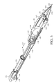
- FIG. 3 is a representative isometric view of a preferred embodiment of the laser assisted drug delivery apparatus of the present invention.
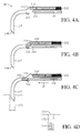
- FIGS. 4A-4D are representative views of a preferred embodiment of a dispenser apparatus with magazine-type manifold of the present invention.
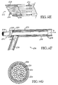
- FIGS. 5A-5B are representative views of a preferred embodiment of a dispenser apparatus with magazine-type manifold of the present invention.
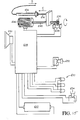
- FIG. 6 is a representative electronics block diagram of a preferred embodiment of the laser assisted drug delivery apparatus of the present invention.
- FIG. 7 is a representative view of a preferred embodiment of a multifurcated manifold means of the laser assisted drug delivery apparatus of the present invention.
- FIG. 8 is a representation of the steps of a method of use of the laser assisted drug delivery apparatus of the present invention.
- FIGS. 9A-9F are representative channel diagrams and regions of drug delivery therein possible with the laser assisted drug delivery apparatus of the present invention.
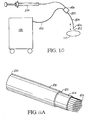
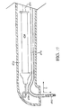
- FIG. 10 is a representative schematic view of a preferred embodiment of the method of use of a drug delivery apparatus of the present invention.
- FIGS. 11A-11C are representative perspective, side and cross section views of a preferred embodiment of the laser delivery means adapted for drug delivery apparatus of the present invention.
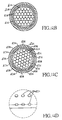
- FIGS. 12A-12D are representative side, cross section and detail views of a preferred embodiment of the leach tube embodiment of a laser delivery means adapted for drug delivery apparatus of the present invention.
- FIG. 12E is a representative plan view of another preferred embodiment of the leach tube embodiment and laser delivery means adapted for drug delivery apparatus of the present invention.
- FIG. 12F is a representative section view of a preferred embodiment of a connector associated with the leach tube embodiment of a laser delivery means adapted for drug delivery apparatus of the present invention.
- FIG. 12G is a representative cross section view of a preferred embodiment of a laser delivery means with infusion tube adapted for drug delivery apparatus of the present invention.
- FIG. 12H is a representative cross section view of a preferred embodiment of a laser delivery means with an infusion channel adapted for drug delivery apparatus of the present invention.
- FIG. 12I is a representative cross section view of a preferred embodiment of a laser delivery means with multi lumen drug conduits adapted for drug delivery apparatus of the present invention.
- FIG. 12J is a representative perspective view of a preferred embodiment of a laser delivery means with diffusion strip adapted for drug delivery apparatus of the present invention.
- FIG. 12K is a representative view of a preferred embodiment of the distal end of a laser delivery means adapted for drug delivery of the present invention.
- FIG. 13A is a representative isometric view of a preferred embodiment of an in-line drug delivery apparatus adapted for addition of drug to the cable of the laser delivery means, which cable extends through the drug delivery apparatus of the present invention.
- FIG. 13B is a partial detail view of the drug reservoir and connector showing addition of drug from the drug reservoir to the fiber cable.
- FIG. 14 is a representative exploded view of a preferred embodiment of an in-line drug delivery apparatus of the present invention.
- FIG. 15 is a representative electronics block diagram of a preferred embodiment of a laser delivery means adapted for drug delivery apparatus of the present invention.
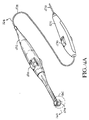
- FIG. 16A is a representative perspective view of a preferred embodiment of a hand-held TMR means in conjunction with an in-line laser delivery means of the present invention.
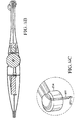
- FIG. 16B is a representative cross section view of a preferred embodiment of a hand held laser delivery means adapted for drug delivery apparatus of the present invention.
- FIG. 16C is a representative detail view of a preferred embodiment of the distal tip of a hand held laser delivery means adapted for drug delivery apparatus of the present invention.
- FIG. 17 is a representative partial view of preferred embodiment of a hand held laser delivery means with advance means adapted for drug delivery apparatus of the present invention.
- FIG. 18 is a representative partial view of preferred embodiment of a hand held laser delivery means with advance means adapted for drug delivery apparatus of the present invention.
- the concept of drug delivery includes any application where a drug or other substance is delivered in the area of laser treatment.
- This invention relates generally to the topic of drug delivery with laser delivery devices, and more particularly to drug delivery in conjunction with TMR in which, for example, antiarrhythmic drugs, growth factors or other drugs or compounds can be delivered to the heart during the TMR procedure.
- drug or “drugs” includes any and all drugs which could or will be used in the manners described herein, including and not limited to the compounds named in the following tables, other medications, antibiotics, vaccines, function regulators, other materials for performing functions including flushing and cooling, stimulating other responses, detection, analysis, monitoring, visualization or control, etc., said solutions comprising waters, saline and the like, solid and semi-solid materials, and in any forms including capsules and granules, implants, etc.
- the present invention includes the delivery of liquid, solid or semi-solid, time release formulations, etc. It is important to consider that a large local concentration of drug may result, particularly in the case of when a solid dissolves in fluid or tissue and becomes bioavailable, unless the particular drugs or other substances being delivered are fairly insoluble or are otherwise formulated to dissolve slowly enough to avoid unacceptably high concentrations, locally or elsewhere. Care must also be taken to avoid solid materials drifting or migrating from the area of intended treatment, such as by implantation, transdermal application, etc.
- Preferred parameters for drug delivery in conjunction through a laser catheter provide a single, acute or multiple acute or sustained administration of the drug to produce a therapeutic effect. Additionally, for certain drug systems, drug half-life should be consistent with the clearance mechanisms present in the environment where the drug is introduced. Drugs that need frequently repeated administration over longer periods of time could require repeated hospitalizations or clinic visits - an exception to this is in the case of cancer chemotherapy, where the patient normally goes to the hospital for drug administration in the course of routine treatment. In the case of a drug administered with TMR, where blood circulation may cause a rapid clearance of any therapeutic delivered in or near the channels, the drug would need a time course of action that is rapid enough to have effect before it is cleared.
- One set of applications of such drug delivery in conjunction with laser procedures involve certain antibody treatments, where it is desirable to target the antibody to the area of intended treatment in order to achieve the highest possible local concentration of a relatively extremely expensive reagent.
- an enzyme linked to an antibody specific to a tumor is delivered and allowed to bind to the tumor cells.
- the two main applications for which laser assisted drug delivery would be advantageous are (1) delivery of angiogenic factors in conjunction with TMR and (2) delivery of a chemotherapeutic to a solid tumor after a laser is used to ablate tumor tissue.
- a normally toxic chemotherapeutic such as doxorubicin or taxol that is made systemically non-toxic by being modified to a prodrug is injected into the tumor. The drug would remain non-toxic until it meets the enzyme linked to the antibody, where the prodrug is converted into active drug. In this way, higher local concentrations of the drug could be created near the tumor than would be possible by traditional chemotherapy, where systemic toxicity is the limiting factor.
- Therapeutics which may be advantageous to deliver through a laser/catheter device can be broadly placed into four overlapping therapeutic categories:
- Antibody agents for example, will appear in all four categories. Certain growth inhibitors can be used for anti-cancer treatment as well as for the treatment of other disease processes. Agents named in the following charts are illustrative and are not meant to be a comprehensive listing of all agents available for the given therapeutic category. Agents appearing as examples in one category may have uses in other therapeutic categories.
- agents which are directed at bone agents implanted in semi-permeable sacs, radioisotopes, and future gene therapies.
- Photodynamic therapy is another important delivery and dosing method.
- Drugs or other compounds which have certain therapeutic or other activity or function can be regulated using such technology.
- Photo-active or photo-labile compounds are those whose activity or function is controlled by light energy. While the use of sensitizing agents or protective groups to block activity of the drug or other compounds in topically applied formulations is known, the use of such protective groups is unknown in conjunction with drugs delivered for angiogenic purposes or in conjunction with TMR.
- “Caged” compounds are compounds which have a photo-active reagent which masks the original characteristics of the compounds.
- these caged or otherwise photo-labile compounds can be delivered to the target tissue or target region in a pharmacologically in-active form.
- the protective group or groups Upon irradiation with laser energy or other, operative electromagnetic radiation, the protective group or groups are caused to be rendered inert, thereby initiating therapeutic activity.
- These photoactive protective groups or "cage” molecules are especially useful in conjunction with highly toxic drugs or marker substances.
- chemotherapeutic agents are particularly toxic and, thus, their toxicity can be eliminated until the agent is delivered to the precise region of the body where it's toxicity will be most effectively and safely used. Irradiation of the photo-labile compound with light energy of a suitable wavelength, frequency and duration can then render the drug or other photo-labile agent active.
- Active compounds which are given systemically have a normal therapeutic window which can be expressed as mg of drug per kg of body weight.
- the amount of agent which is therapeutically acceptable when administering a drug locally can be approximated as mg of drug per kg of target treatment area (e.g. organ weight), optimized accordingly with consideration of toxicity and mechanism of drug action.
- Agents delivered to a specific site can achieve high local concentrations at the delivery point.
- Optimal drug dose may scale differently when the drug is administered locally rather than systemically.
- the amount of a given agent that should be delivered in order to achieve a therapeutic effect must be optimized accordingly with consideration of toxicity levels (both locally and systemically), mechanism of drug action, drug clearance mechanisms, and drug diffusion levels.
- agents work by either promoting or inhibiting blood clot cascade pathways. These agents are actual blood clot cascade participants, which mimic actual blot clot cascade participants, or agents which act as enzymes or inhibit enzymes that are associated with the blood clot cascade. Some examples of agents in these categories include:
- agents in the category include:
- agents in the category include:
- Cancer therapy can proceed along several different lines, all of which seek to kill or limit the growth of cancer cells while doing minimal damage to the host.
- any difference in cancer cell properties e.g. metabolism, cell-surface antigen presentation
- these differentiating factors may be created and/or exploited.
- the local administration of cytotoxins or growth inhibitors may allow higher local concentrations of the compounds than would be achievable by systemic administration.
- Differences in cell-surface recognition molecules may be a site for antibody therapy.
- Differences in tumor morphology are also potential sites of intervention: for example, anti-VEGF may be useful in retarding the vascularization of the interior of a solid tumor, thereby slowing its growth rate.
- agents in the category include:
- TMR is based on the theory that blood will flow directly from the left ventricle into the channels and then into the myocardial vascular plexus. Although the mechanism of TMR is still being investigated, there is some indication that the channels remain patent for a significant period of time following their creation. There is a question of whether blood washing in and out of the channels and the attendant diffusion into the muscle provides an adequate oxygen supply to the myocardium. The possibility exists that since TMR induces some secondary vascularization, whatever signal is given to induce vascularization could be pharmacologically amplified. Mechanisms for this type of induced revascularization may stem from factors induced by tissue damage (VEGF or other growth-factor derived response, or perhaps heat-shock proteins produced by thermal damage caused by the laser). Regardless of the actual mechanism, an angiogenic factor used in conjunction with TMR may increase the effectiveness of the technique.
- tissue damage VEGF or other growth-factor derived response, or perhaps heat-shock proteins produced by thermal damage caused by the laser.
- VEGF vascular endothelial growth factor
- FGF-1, FGF-2, EGF vascular endothelial growth factor
- VEGF vascular endothelial growth factor
- FGF-1, FGF-2, EGF vascular endothelial growth factor
- VEGF vascular endothelial growth factor
- VEGF has been shown to be effective in improving vascularization in the rabbit ischemic hindlimb model after a single bolus administration.
- VEGF also has a serum half life of less than 6 minutes (unpublished results), and certain isoforms of VEGF have the property to bind to the cell surface - i.e. VEGF may not need to be present for very long in order to have an effect.
- VEGF therapy alone will not be shown to be as effective as TMR alone.
- Angiogenesis produced by VEGF in the myocardium may have limited effectiveness when the cause of ischemia is occlusion of coronary arteries: this limits the amount of blood available to the myocardium.
- the advantage of a TMR/VEGF combination treatment is that the transmural channels created in TMR could provide a source of blood to the newly vascularized myocardium that is otherwise unavailable.
- bFGF Basic fibroblast growth factor
- FGF-2 Basic fibroblast growth factor
- FIGS. 1 through 7 represent laser drug delivery apparatus using separate laser and drug conduits which meet at a manifold which enables separate delivery of laser energy and drugs through a common outlet.
- FIGS. 10-18 represent laser drug delivery apparatus which combines the drug with the laser apparatus.
- FIG. 1 is a representative schematic view of a preferred embodiment of a laser delivery means adapted for manifold drug delivery apparatus of the present invention.
- a laser source 100 provides laser energy. Laser energy is delivered via laser delivery means 102 . It will be understood that said laser delivery means 102 can be any suitable laser delivery means including individual optical fibers, bundles of optical fibers, cables, rods, waveguides, articulating arms or other devices known to those skilled in the art.
- the drug reservoir and dispenser mechanism 104 dispenses drugs, solutions, solids, or other substances via drug conduit 108 to manifold means 106 .
- the drug conduit 108 will convey dispensed drug, including flushing and saline solutions, to be delivered to the target tissue 110 from the drug reservoir means and dispenser mechanism 104 to the manifold means 106 .
- FIG. 1 is schematic and representative only, and the invention encompasses delivery of more than one drug via manifold means 106 which associates the drug or other substances with the laser delivery means located at any place within the physician's armamentarium.
- FIG. 2 is a representative side view of a preferred embodiment of the manifold means 106 of the laser assisted drug delivery apparatus of the present invention.
- drug to be delivered to a target region in the human body flows from drug conduit 108 into a drug inlet 114 of the manifold means 106 of the present invention.
- the distal end 112 of the laser delivery means enters the laser inlet 116 .
- Fluid seal 200 will prevent backflow through the laser inlet 116 of drug, solutions or other substances.
- the manifold means 106 preferably terminates in tubular, common tube 117 having an aperture, or optionally, a hollow, slant-cut tubular surgical or other needle tip 118 .
- This tip 118 can be formed from the same material as used for the manifold means 106 , or another material, such materials in general including but not limited to tantalum, stainless steel, glass, etc. It will be understood that when employing either a percutaneous approach or a surgical approach, a tip 118 at the distal end 112 of the laser delivery means 102 can be used initially to pierce a surface of the target area. For TMR procedures, this will minimize bleeding from the epicardium, improve visibility in the region and reduce the incidence of adhesions between the epicardial surface and the pericardial sac.
- piercing will stabilize the device, for example on the surface of the heart or from within a heart chamber.
- the piercing mechanism may be angled fibers and suction may also be used at the target surface, with or without a piercing mechanism.
- the common tube 117 shown defines a single lumen but it will be understood by those skilled in the art that more than 1 lumen may be included and that the common tube is designed to dispense drugs at the delivery site of the laser energy.
- a fiber or other laser delivery means with or without piercing tip 118 , a predetermined distance into tissue such as myocardium and delivering laser energy will create an opening such as a TMR channel or other treatment site for delivery of drug therein.
- Retrolasing can also be performed with the methods and apparatus of the present invention.
- the manifold means 106 embodiment described herein as a bifurcated or multifurcated needle is only representative of various such devices possible and considered within the scope of this invention.
- additional configurations for the needle include wye ("Y”) and vee ("V”) shapes, etc.
- FIG. 3 is a representative isometric view of a preferred embodiment of the laser assisted drug delivery apparatus of the present invention.
- the laser assisted drug delivery apparatus includes an elongated housing 132 .
- the housing 132 of the apparatus defines a handle portion 120 and a neck portion 122 .
- the housing 132 contains means for controllably dispensing, in precise amounts as desired, drug contained within the one or more reservoir means 134 .
- Preferred embodiments of the apparatus further include laser delivery means advance means 166 .
- the means for controllably dispensing such substances includes a drug reservoir 134 , in this case a type of syringe.
- a piston, plunger or pellet dispenser 136 is moved axially by lead arm 138 , driven by lead screw 140 .
- a power source 142 powers a small motor 144 , which is coupled to the lead screw 140 by means of gearhead 146 .
- a stepper motor is used.
- the motor 144 is actuated by signals generated and received by controller 148 , for example electronics mounted on a printed circuit board.
- a dispense button 150 as shown in FIG. 4, when manually depressed, will dispense at least one aliquot of drug. It will be understood that the controller and logic thereof may also be programmed to dispense a series of aliquots, at predetermined time intervals or according to other parameters, into the manifold means 106 from drug conduit 108 .
- FIGS. 4A-4D are representative views of a preferred embodiment of a dispenser apparatus with magazine-type manifold of the present invention.
- Drug unit, pellet, capsule or other solid or semi-solid 210 is stored within drug inlet 114 .
- the stack of drug units or other drug solid 210 is urged forward by spring member 212 .
- Blocking member 214 prevents the forward most drug unit 210 from entering the common tube 117 and tip 118 when the distal tip 112 of laser delivery means 102 is not extended through the manifold means 106 .
- the distal end 112 of laser delivery means 102 is extendable through manifold means 106 and through common tube 117 and tip 118 .
- a TMR channel or other laser and/or mechanically created opening 172 can be formed in tissue by advancing the distal tip 112 of laser delivery means in direction D . Thereafter, laser delivery means can be retracted, thus allowing the forward most drug solid 210 to be loaded into manifold means 106 where it will be held in place as shown by blocking member 214 .
- the mechanical apparatus shown for dispensing such drug units can be modified to include optical sensors, step motors, etc., and will be included within the scope of the present invention. As shown in FIGS.
- the distal end 112 of laser delivery means will act as a push rod and will cause drug solid 210 to be dispensed through tip 118 and deposited within opening 172 .
- the opening may then seal 216 or be sealed naturally or otherwise.
- FIGS. 5A and 5B are representative views of a preferred embodiment of a dispenser apparatus with magazine-type manifold of the present invention.
- Drug solids 210 each having a small end section 218 are used. Such drug solids 210 will be pushed by plunger 220 into common tube 117 and through tip 118 .
- distal end 112 will engage the end section 218 of drug solid 210 thereby advancing it as well, as shown in FIG. 5B.
- drug solid 210 can be dispensed and deposited as desired, for example, within blind or dead-end TMR channels, open-ended channels, etc. It will be understood that numerous other embodiments of the drug unit advance mechanism are possible and will all be considered within the scope of the method and apparatus of the present invention.
- TMR means will include, and are not limited to, finger tip devices, guide block devices, and various handpieces, with features including but not limited to fiber advance means, depth stop adjust means, rotation control means to form dual and multiple channels from a single opening.
- a preferred embodiment of the present invention for use in surgical and minimally invasive surgical (MIS) procedures includes, as shown, a head portion 164 which is placed against or adjacent the exterior of the heart to be revascularized or otherwise treated.
- a laser delivery means 102 enters the rear portion 124 of the housing 132 and is movable as shown in direction B therein. It will be understood that the laser delivery means 102 may also be retracted in the opposite direction therethrough.
- a thumbwheel or other laser advance means 166 is used to automatically advance the distal end 112 of the laser delivery means 102 for forming a plurality of TMR channels into which drug can be deposited prior to, simultaneously with, and/or subsequent to said forming.
- the piston 136 In operation, once the drug reservoir is charged with a drug as described above, or a saline or other flushing solution for flushing, cooling and/or otherwise treating the laser created openings such as TMR channels, the piston 136 will be positioned in an extended position, as shown. When actuated, the piston 136 will be driven in direction C . Resultant flow of metered quantities of drug will be through drug conduit 108 and into the drug inlet 114 of manifold means 106 . From there, drug flow is through tip 118 and either directly into the opening 172 or into opening 172 surrounding laser delivery means 102 . (See FIG. 7)
- a preferred embodiment of the drug delivery apparatus 104 can include any of a wide range of drug reservoirs.
- Typical reservoir 134 volumes are 1, 2 and/or 3 milliliters.
- Typical aliquots, as integral fractions of a complete piston stroke, for dispensing in an automated manner, i.e. upon activation of some button or switch which would at least initiate drug flow and then either continue until released or otherwise deactivate or continue for a predetermined time or volume of delivery are 1/30, 1.50, 1/100 and 1/300 of the entire reservoir volume.
- a selector means such as a selector switch (not shown), optionally located in housing 132 may be provided for such user settings selection.
- a clear plastic door covering such selector means provides immediate information to the operator of the apparatus as to current settings and helps prevent undesired and/or unintentional parameter adjustments.
- Another beneficial aspect to the present invention is the ability to use the apparatus for flushing and cooling. Saline solution and blood, as well as solutions containing drugs or other specific compounds, can all be controllably dispensed through the apparatus of the present invention.
- the method and apparatus of the present invention include those systems in which the drug reservoir is on board as well as off board. Reservoirs containing drug, flushing or cooling solutions, etc., could be maintained at some convenient place within the armamentarium of the procedure connected to the apparatus of the present invention with tubing, etc. It is also convenient to provide an apparatus with connections to one or more reservoirs external to the apparatus as well as to one or more reservoirs on-board, as shown.
- FIG. 6 is a representative electronics block diagram of a preferred embodiment of the laser assisted drug delivery apparatus of the present invention. It will be understood that the following is representative of a single embodiment of the present invention, a large number of additional preferred embodiments will be readily apparent and included within the scope of the present invention.
- Fiber advance activation means includes a switch means 190 such as thumbwheel 166 .
- Switch means 190 switches power from power source 142 to fiber advance mechanism 192 to advance laser delivery means 102 in direction B by fiber advance mechanism 192 .
- Thumbwheel 166 or other fiber advance means will be operative through a given angular range, for example 60° ⁇ 15°.
- Switch means 190 also comprises, in a preferred embodiment, an audible indicator, such as a beeper, to indicate to the operator fiber position - as an example, a first beep or set of beeps indicating a retracted position, and other beeps or sets of beeps indicating other positions including a fully advanced position, a position 5 millimeters or more or less before a hard stop, etc.
- an audible indicator such as a beeper
- Power source 142 will permit illumination of one or more of a plurality of indicators, including aliquot size indicator lights 152 .
- Aliquot size selection means 154 typically a toggle or push button type switch, will permit the user to verify and/or select the size of the aliquot to be operatively dispensed.
- dispense activation means 150 such as a toggle or push button, make and break switch, etc.
- dispense activation means 150 will send a signal directly to controller 148 to dispense one or more aliquots in a predetermined time period.
- Controller 148 will actuate motor 144 so as to cause rotation of lead screw 140 .
- Optical flag 156 configured to rotate in unison with lead screw 140 , will allow detection of rotation of lead screw 140 by sensors 158 .
- sensors may include infrared LED sensors, motion sensors, etc.
- cycle complete indicator means 160 Such cycle complete indicator means 160 could comprise a beeper to produce a beep or series of beeps or other audible sounds, or to activate indicator lights, etc. Such cycle complete indicator means 160 could also be configured and/or actuated to indicate an empty drug reservoir, other transient or set operation parameters, apparatus diagnostics, etc.
- FIG. 7 is a representative view of a preferred embodiment of a multifurcated manifold means 188 of the laser assisted drug delivery apparatus of the present invention.
- a plurality of drug inlet branches 194 as well as a laser delivery means 102 inlet branch 196 comprise the multifurcated manifold means 188 .
- the multifurcated manifold means 188 is shown diagrammatically, and that numerous embodiments for such manifold means are possible.
- the laser assisted drug delivery apparatus of the present invention could include a plurality of drug reservoirs, including saline solution, for flushing the device, flushing TMR channels or other laser created openings, or to deposit one or more different drug solutions or other substances therein.
- Such apparatus would also contain a plurality of drug reservoirs 198 , each situated either proximal to or distal to the main housing of the apparatus of the present invention, each with its own corresponding drug inlet channels 194 , and a plurality of separate dispense activation buttons and associated piston, etc., or other internal configuration allowing for selectively dispensing such plurality of drug solutions, saline flush, aspiration solution or other substances.
- a plurality of drug reservoirs 198 each situated either proximal to or distal to the main housing of the apparatus of the present invention, each with its own corresponding drug inlet channels 194 , and a plurality of separate dispense activation buttons and associated piston, etc., or other internal configuration allowing for selectively dispensing such plurality of drug solutions, saline flush, aspiration solution or other substances.
- FIG. 10 is a representative schematic view of a preferred embodiment of a combined drug delivery apparatus of the present invention.
- a laser source 100 provides laser energy.
- Laser energy is delivered via laser delivery means 502 .
- said laser delivery means 502 can be any suitable laser delivery means including individual optical fibers, bundles of optical fibers, cables, rods, articulating arms or other devices known to those skilled in the art.
- the laser delivery means adapted for drug delivery apparatus 504 dispenses one or more drugs, drug solutions, solids, or other substances such as saline, flushing or cooling solutions from a drug reservoir 534 contained therein, as shown in FIG. 13A, via connector 506 to drug conduit 508 .
- the drug conduit 508 contains drugs to be delivered to the target tissue 110 in conjunction with the laser delivery means 502 .
- drug conduit 508 comprises a leach tube, or end tube(s), or other means for delivering the drug(s) dispensed by the laser delivery means adapted for drug delivery apparatus 504 preferably in the region of the distal end 512 of the laser delivery means 502 .
- FIG. 10 is schematic and representative only, and the invention encompasses delivery of more than one drug(s) and/or other substances via a connector which associates the drug or other substances with the laser delivery means located at any place within the physician's armamentarium.
- FIGS. 11A-11C are representative perspective, side and cross section views of a preferred embodiment of the laser delivery means adapted for drug delivery apparatus of the present invention.
- the distal end 512 of the laser delivery means 502 will preferably be disposed within the drug conduit 508 distal to the connector 506 .
- a proximal end 520 of the drug conduit 508 is located adjacent the connector 506 .
- Drugs are communicated from the drug delivery apparatus 504 and pass into drug conduit 508 .
- the drug conduit 508 portion of the embodiment can be made of any suitable material, including but not limited in any way to high density, polypropylene, "crystal-flex" type tubing. Its manufacture and diameter will be dependent upon the type of laser delivery means 502 being used, i.e., single fiber, fiber bundle, waveguide, rod, or waveguide or cable carried within an articulating arm, etc.
- a tantalum band 200 or other marking device may be placed at the end of the apparatus adjacent the distal end 512 of the laser delivery means 502 . It will be understood that the tantalum band 200 serves to make the distal end 512 of the laser delivery means 502 radio opaque for visualization. A wide variety of other visualization-enhancing attachments or materials of construction may be used in various ways and are all considered within the scope of this invention.
- Drug will flow or otherwise be transferred through a drug channel 518 , formed by the space between the inner wall surface of the drug conduit 508 and the laser delivery cable 502 , passing into or around a laser created opening through the distal end 522 of the drug conduit 508 .
- FIGS. 12A-12D are representative side, cross section and detail views of a preferred embodiment of the leach tube embodiment of a laser delivery means adapted for drug delivery apparatus of the present invention.
- the laser delivery means 502 will be disposed within the drug conduit 508 .
- the distal end 522 of the drug conduit 508 forms the leach tube embodiment - a plurality of (i.e. one or more) perforations 524 formed through the wall of drug conduit 508 allow drugs in space 518 to flow or otherwise be transmitted through drug conduit 508 .
- the distal end 512 of the laser delivery means 502 preferably extends past the distal end 522 of the drug conduit 508 .
- a preferred type of laser delivery means 502 consists of a bundle of individual optical fibers 514 .
- the outer jacket 516 will also contain an epoxy or other polymeric or other suitable material for "potting" the fiber bundle. This potting material will serve to hold the fibers in place relative to each other and the outer jacket 516 .
- Outer jacket 516 such as a thin plastic tubing material, surrounds the bundle of individual fibers 514 , and serves to hold them together in an operative arrangement. This outer jacket 516 will also serve to reflect any light leaks from the fibers back into the fibers, or at least out the distal end 512 of the laser delivery means 502 .
- the combination of outer jacket 516 and drug conduit 508 defines an interstitial drug channel 518 through which drugs can be conveyed from the connector 506 through conduit 508 and out the plurality of perforations 524 . It will be understood that the outer jacket 516 is optional and may be omitted.
- utilizing a single fiber mounted within conduit 508 will result in drug delivery from the plurality of perforations 524 in essentially the same manner as described above.
- drug solution or other substances will flow from the connector 506 around each of the individual fibers 514 of the bundle, thus resulting in percolation of drug out of the drug conduit 508 at either or both the plurality of perforations 524 and the distal end 512 of the fiber bundle.
- individual perforations 524 are spaced about outer jacket 516 . It will be understood that more or fewer perforations may be used, and perforations located at various axial positions located adjacent the distal end 522 of the drug conduit 508 .
- the perforations 524 could be replaced with a portion of permeable or semi-permeable material to controllably deliver drug solution or other substances therefrom.
- FIG. 12E is a representative plan view of another preferred embodiment of the leach tube embodiment and laser delivery means adapted for drug delivery apparatus of the present invention.
- the laser delivery means 502 comprises a bundle of individual optical fibers 514 each cleaved or otherwise positioned adjacent each other, having a distal end 512 formed with an angle cut piercing tip 526 .
- this piercing tip 526 can be either formed integral with the drug conduit 508 or it can be formed by the outer jacket 516 and/or marking band 200 at the distal end 512 of the laser delivery means 502 itself.
- This piercing tip can be formed from the same material as used for the drug conduit 508 or fiber outer jacket 516 .
- a piercing tip 526 at the distal end 512 of the laser delivery means 502 can be used initially to pierce a surface of the target area.
- this will minimize bleeding from the epicardium, stabilize the device in the tissue, improve visibility in the region and reduce the incidence of adhesions between the epicardial surface and the pericardial sac.
- an optional piercing device or means will stabilize the device. Then, advancing or retracting a fiber or other laser delivery means a predetermined distance into or out of myocardium while delivering laser energy will create an opening, such as a TMR channel or other treatment site, for delivery of drugs therein.
- FIG. 12F is a representative section view of a preferred embodiment of a connector 506 associated with a laser delivery means adapted for drug delivery apparatus of the present invention.
- This representative view of the connector 506 is shown with an optical fiber bundle or other laser delivery means 502 .
- Drug is introduced to the connector 506 through one or more drug ports 528 .
- the laser delivery means 502 enters the connector at laser delivery means port 530 . Both of said ports are located at the proximal end 520 of the drug conduit 508 .
- the drug channel 518 extends from the proximal end 520 of the drug conduit 508 through to the distal end 522 of conduit 508 . Seal means 602 will prevent backflow through conduit means 508 of drug, solutions or other substances.
- FIG. 12G is a representative cross section view of a preferred embodiment of a laser delivery means with infusion tube 604 adapted for drug delivery apparatus of the present invention.
- the infusion tube 604 is an appropriately sized tube made of drug and other substance-compatible material, e.g. teflon.
- Infusion tube 604 extends from the connector 506 (not shown) at which point it receives the drug being transmitted therethrough through its proximal end (not shown), to its distal end 606 at or near the distal end 512 of the laser delivery means 502 .
- a plurality of perforations in an optional conduit 508 also would allow infusion of drug from drug channel 518 through optional leach holes or at the distal ends of the individual fibers 514 of the laser delivery means 502 if so desired.
- the distal end of the infusion tube 604 terminates in essentially the same plane as defined by the distal end faces of the individual fibers 514 of laser delivery means 502 .
- FIG. 12H is a representative cross section view of a preferred embodiment of a laser delivery means with an infusion channel 606 adapted for drug delivery apparatus of the present invention.
- an optional drug channel 518 may also be provided.
- FIG. 12I is a representative cross section view of a preferred embodiment of a laser delivery means with a multi lumen drug conduit adapted for drug delivery apparatus of the present invention.
- a plurality of lumens 612 extend from the proximal end 520 of the drug conduit 508 along the length of the drug conduit to its distal end 522 . It will be understood that these plurality of lumens 612 can be individual elongated tubes placed within the laser delivery means 502 or adjacent to the laser delivery means 502 . In a preferred embodiment, the plurality of lumens 612 can be formed integrally with the drug conduit 508 . As described above, the plurality of lumens 612 thereby provide one or more individual drug channels 518 communicating drug therethrough.
- FIG. 12J is a representative perspective view of a preferred embodiment of a laser delivery means with diffusion strip adapted for drug delivery apparatus of the present invention.
- a drug or other substance 614 is affixed directly to the distal end 512 of laser delivery means 502 .
- the drug or other substance 614 can be a solid material or other material placed on an adhesive backed layer to enable fixation of the drug or other substance 614 to the distal end of laser delivery means.
- delivery of the drug or other substance 614 is achieved by creation of an opening in the target tissue by the distal end 512 of laser delivery means 502 and diffusion of the drug or substance 614 into the surrounding tissue in contact with the drug.
- FIG. 12K is a representative view of a preferred embodiment of the distal end 512 of a laser delivery means 502 adapted for drug delivery of the present invention.
- the hollow opening or drug channel 518 is formed by a plurality of individual optical fibers 514 arranged in a bundle or otherwise.
- a certain divergence angle 700 for example between about 11 and about 14 degrees, one could calculate an operative range of diameters 702 which would provide ablation at a certain distance 704 from the distal end 512 of the laser delivery means 502 , as desired.
- FIG. 13A is a representative isometric view of a preferred embodiment of an in-line drug delivery apparatus for dispensing drug into the conduits described above where the laser delivery cable passes through the drug delivery apparatus itself.
- FIG. 13B is a partial detail view of the connector of a preferred embodiment.
- FIG. 14 is a representative exploded view of an in-line drug delivery apparatus of the present invention. All of these embodiments are intended to allow passage of drug from a reservoir means 534 through a connector 506 into a drug conduit 508 , associated in any of a number of different ways (see FIGS. 11A-12I) with laser delivery means 502 .
- the laser delivery means can be directed through any one of a plurality of laser delivery means handpiece apparatus, including finger tip devices, guide block devices, J-grip handpieces, etc.
- handpiece apparatus including finger tip devices, guide block devices, J-grip handpieces, etc.
- Such handpieces with features including but not limited to fiber advance means, depth stop adjust means, rotation control means.
- laser delivery may be provided to the target tissue without a handpiece, and may also be directed through a waveguide or articulated arm.
- laser delivery means adapted for in-line drug delivery apparatus 504 includes an elongated housing 532 .
- the housing 532 contains means for controllably dispensing, in precise amounts as desired, drug contained within the housing 532 .
- the means for controllably dispensing such substances includes one or more drug reservoirs 534 , in this case a type of syringe.
- a piston or plunger 536 is moved axially by lead arm 538 , driven by lead screw 540 .
- a power source 542 such as a battery, powers a small motor 544 , coupled to the lead screw 540 by means of gearhead 546 .
- a stepper motor is capable of providing precise, repeated small drug bolusses.
- the motor is actuated by signals generated and received by controller 548 , for example electronics mounted on a printed circuit board.
- a laser delivery means 502 is also mounted in a fixed, non-movable position within the housing 532 , and extends through the housing 532 to a handpiece or other distal tip apparatus (not shown) positioned in operative relationship to the target surface.
- the piston 536 In operation, once the drug reservoir is filled, the piston 536 will be positioned in an extended position, as shown. When actuated, the piston 536 will be driven in direction C . Resultant flow of metered quantities of drug will be through the one or more drug ports 528 and into the connector 506 . From there, drug flow is through drug channel 518 surrounding laser delivery means 502 , from the proximal end 520 toward the distal end 522 of drug conduit 508 .
- a preferred embodiment of the in-line drug delivery apparatus 504 can include any of a wide range of types of drug reservoirs 534 , and may include more than one reservoir for dispensing several different drugs therefrom.
- Typical reservoir volumes are 1, 2 and/or 3 milliliters.
- Typical aliquots, as integral fractions of a complete piston stroke, for dispensing in an automated manner, i.e. upon activation of some button or switch which would at least initiate drug flow and then either continue until released or be otherwise deactivated, or continue for a predetermined time or volume of delivery, are 1/30, 1/50, 1/100 and 1/300 of the entire reservoir volume.
- a selector means such as a selector switch (not shown) is optionally located inside the housing 532 in a portion of the housing for such user settings selection.
- a clear plastic door covering such selector means provides immediate information to the operator of the apparatus as to current settings and helps prevent undesired and/or unintentional parameter adjustments.
- a dispense button 550 when manually depressed, will dispense at least one aliquot. It will be understood that the controller and logic thereof may also be programmed to dispense a series of aliquots, at predetermined time intervals or according to other parameters, into the drug channel 518 defined by the drug conduit 508 .
- FIG. 15 is a representative electronics block diagram of a preferred embodiment of a laser delivery means adapted for in-line drug delivery apparatus of the present invention. It will be understood that the following is representative of a single embodiment of the present invention, a large number of additional preferred embodiments will be readily apparent and included within the scope of the present invention.
- Power source 542 will permit illumination of one of a plurality, more or less, of aliquot size indicator lights 552 .
- Aliquot size selection means 554 typically a toggle or push button type switch, will permit the user to verify and/or select the size of the aliquot to be operatively dispensed.
- dispense activation means 550 such as a toggle or push button, make and break switch, etc.
- dispense activation means 550 will send a signal directly to controller 548 to dispense one or more aliquots in a predetermined time period.
- Controller 548 will actuate motor 544 so as to cause rotation of lead screw 540 .
- Optical flag 556 configured to rotate in unison with lead screw 540 , will allow detection of rotation of lead screw 540 by sensors 558 .
- sensors may include infrared LED sensors, motion sensors, etc.
- cycle complete indicator means 560 Such cycle complete indicator means 560 could comprise a beeper to produce a beep or series of beeps or other audible sounds, or to activate indicator lights, etc. Such cycle complete indicator means 560 could also be configured and/or actuated to indicate an empty drug reservoir, other transient or set operation parameters, apparatus diagnostics, etc.
- FIG. 16A is a representative perspective view of a preferred embodiment of a laser delivery means adapted for in-line drug delivery apparatus 504 of the present invention in conjunction with a hand held laser handpiece 562 .
- FIG. 16B is a representative cross section view of a preferred embodiment of such a laser handpiece 562 .
- FIG. 16C is a representative detail view of a preferred embodiment of such a laser handpiece 562 .
- laser handpieces 562 will include, and are not limited to, hand-held devices with fiber advance mechanisms, fiber rotating mechanisms, mechanisms for securing a TMR head to a specific point on the heart, such as any of various suction-type devices, or within a chamber of the heart, catheter devices for vascular approaches to the heart, intra-coronary TMR devices, preformed or shapeable devices for positioning one or more TMR channels precisely and accurately, etc.
- fibers may be used without handpieces or laser energy may be delivered through articulating arms with or without waveguides.
- the laser handpiece 562 shown is hand-held, wand shaped, and has a head portion 564 which is placed against or adjacent myocardium to be revascularized or otherwise treated.
- a thumbwheel 566 is used to advance the distal end 512 of the laser delivery means 502 within the distal end 522 of the drug conduit 508 containing the drug transmitted therethrough for forming a plurality of laser created openings, such as TMR channels.
- a needle 616 is disposed adjacent head 564 of laser handpiece 562 .
- the hollow needle 616 is used to pierce a surface of the target tissue for creation of a laser-created opening therein.
- the laser delivery means 502 adapted for in-line drug delivery of the present invention can be extended through the needle 616 .
- a piercing needle 616 at the distal end 512 of the laser delivery means 502 can be used initially to pierce a surface of the target area.
- FIG. 17 is a representative partial view of preferred embodiment of a hand held laser delivery means with advance means adapted for drug delivery apparatus of the present invention.
- the laser delivery means 502 will be advanced and retracted in directions D , and thus, drug port 528 will also be non-stationary. Therefore, to allow relative movement between the drug port 528 where the drug is supplied to drug channel 518 , a section of flexible tubing material 710 is coupled between drug reservoir 534 and the proximal end 520 of drug conduit 508 . Drug communication between the reservoir 534 and the drug conduit 508 is therefore maintained, even during advance of the laser delivery means 502 .
- FIG. 18 is a representative partial view of preferred embodiment of a hand held laser delivery means with advance means adapted for drug delivery apparatus of the present invention.
- a similar type of aperture connector 506 as shown in FIG. 13B is utilized.
- Drug flow in direction A will cause drug flow between outer jacket 516 and individual fibers 514 of laser delivery means 502 .
- lateral fiber advancement and retraction in directions D will cause the opening in the outer jacket to move within the connector 506 .
- fluid seals 720 will prevent leakage or other loss of drug from the system, for example by flowing the wrong direction through the drug conduit toward the proximal end of laser delivery means 502 .
- FIG. 8 is a representation of the steps of a method of use of the laser assisted drug delivery apparatus of the present invention.
- Step 1 shows tip 118 of manifold means 106 inserted into first surface 168 .
- the first surface 168 can be an epicardial surface, an endocardial surface, or other structure within the human body in which a drug is to be delivered.
- fluid seal 200 can be located either within or adjacent drug inlet 114 and/or within or adjacent laser inlet 116 .
- Such fluid seal means 200 typically include a compressible rubber or other material gasket or stopper arrangement.
- a guide block 202 or other head such as head 164 , serves to maintain the device and the manifold means stationary with respect to surface 168 , with or without suction.
- a TMR channel or other laser created opening 172 is formed by extending the distal end 112 of laser delivery means 102 through the laser inlet 116 and the tip 118 of the manifold means 106 .
- the TMR channel or other laser created opening 172 can terminate at a point within myocardium 170 or can pass entirely through the structure and a second surface 174 .
- the second surface 174 could likewise be either an endocardial surface or other structure defining surface within the human body. It will be understood that during this step, i.e. as the opening 172 is being formed, drug can be dispensed through the first inlet channel 114 for deposit within the opening 172 , in this case the drug will flow around and/or surround the distal end 112 of laser delivery means 102 .
- step 3 laser delivery means 102 is retracted from opening 172 .
- drug may be dispensed through the drug inlet 114 of manifold means 106 for deposit within opening 172 .
- step 4 the tip 118 and guide block 202 is removed, leaving a TMR channel or other laser created opening 172 behind, typically containing dispensed drug solution or other substances therein.
- Step 1 the distal end of the laser delivery means, with or without a piercing device, is being inserted through a first surface 168 into target area 170 .
- the perforations in the drug conduit will be located at some point within the TMR channel or other laser created opening 172 .
- slight retraction of laser delivery means adapted for in-line delivery of drug will accurately and precisely and operatively position the perforations within the opening 172 .
- step 3 drug is dispensed through the perforations 524 of the drug conduit so as to enter the opening 172 .
- the drug conduit with laser delivery means 502 is retracted from the opening 172 , the dispensed drug remaining therein, or flushing through the channel for TMR type procedures with channels or other laser created openings through the endocardium or other surfaces.
- the above steps comprise one method of drug delivery. Other steps may include delivery of drug following piercing, or following partial creation of a channel followed by additional lasing.
- FIGS. 9A-9F are representative channel diagrams and regions of drug delivery therein possible with any of the laser assisted drug delivery apparatus of the present invention.
- a single TMR channel or other laser created opening 172 can be formed with the present invention.
- Such opening can originate from any first surface 168 of essentially any structure within the human body.
- a wye ("Y") shaped TMR channel or other laser created opening 176 can also be formed.
- Y wye
- a vee (“V”) shaped TMR channel or other laser created opening 180 drug solution or other substance can be deposited at essentially any point therein.
- FIGS. 9A, 9E and 9F show "blind" or dead-ended channels. As made clear by the foregoing, these types of channels will be especially suited for drug delivery, especially with regard to drug solids, pellets, time release formulations, etc. Such channel patterns can be created often by making a single opening at the surface, creating a first channel in a first, predetermined angle, retracting the laser delivery means and re-orienting the laser fiber or the device so as to form one or more subsequent channels at different angles to each other.
- FIG. 9F shows a TMR channel created just a short distance below and essentially parallel to the surface of the tissue. Such revascularization just below the typically 1-3 millimeter boundary layer of surface capillaries will encourage their growth downward into muscle, deeper myocardium or other parts of the tissue.
- retro-lasing can also be performed using the apparatus and methods of the present invention.
- This novel use includes the steps of advancing a fiber or other laser delivery means, preferably with a tip a predetermined distance into the myocardium and then delivering laser energy to create a TMR channel or other treatment site while retracting the fiber, laser delivery means or other functional device. Therefore, with regard to TMR, inasmuch as laser energy is only delivered during retraction of the fiber, the possibility of advancing the fiber too far and lasing through the epicardium is eliminated, as are complications arising from such epicardial perforations including but not limited to cardiac tamponade (a buildup in the pericardial sac of an excess of fluid such as blood), proliferation of adhesions, etc.
- drug solutions or other substances can be deposited at essentially any operative time within the procedure, either during piercing, after piercing, during retro-lasing or at some point thereafter.
- the present invention is intended for use with any medical laser.
- the Holmium or excimer laser is particularly suited to the present invention.
- any suitable laser source, pulsed or otherwise could provide laser energy to the laser delivery means of the present invention for performing the method of the present invention.
- the catheter and surgical equipment, including laser delivery means, referred to in the present document as well as that known and used in medicine and other disciplines today and in the future, will be included in the scope of this disclosure.
- Such laser delivery means include, but are not limited to, individual optical fibers as well as bundles of fibers with and without piercing tips and with or without firing tips or fiber ends having shaped or contoured end faces for selectively diverging the laser beam or other laser energy diverging means, rods, cables, articulated arms, mirrors configurations and other laser delivery means with and without focusing lens and the like. It will also be understood that the apparatus and method of the present invention as described herein, including the novel combination or use with of any conventional mechanism or method which are known to those skilled in the art, are included within the scope of this invention.
Abstract
Description


Claims (22)
- An apparatus for laser assisted drug delivery comprising means for delivering laser energy to, and means for delivering at least one drug to, one or more target areas within the human or animal body.
- A laser assisted drug delivery apparatus according to claim 1 for delivering laser energy and for dispensing one or more selected drugs to one or more target areas within the human body, the apparatus comprising, in combination:at least one drug inlet for receiving and transmitting the one or more selected drugs;at least one laser inlet for receiving and guiding a laser delivery means; anda common tube, the at least one drug inlet and the at least one laser inlet in operative communication with the common tube such that a distal end of a laser delivery means can be extended through a laser inlet and the common tube to a point adjacent the one or more target areas to direct laser energy to the one or more target areas and the one or more selected drugs can be dispensed into a drug inlet and through the common tube.
- The apparatus of claim 2 further comprising a piercing means for piercing a surface adjacent the one or more target areas.
- The apparatus of claim 2 or claim 3 further comprising:
one or more reservoirs for containing the one or more selected drugs to be dispensed. - The apparatus of any one of claims 2 to 4 further comprising at least one dispensing means for dispensing the one or more selected drugs from the one or more reservoirs into the drug inlet.
- The apparatus of claim 5 further comprising a control mechanism for selecting and dispensing controlled volumes of the one or more selected drugs from the reservoir means.
- The apparatus of any one of claims 2 to 6 further comprising:
suction means for coupling the apparatus to the one or more target areas as desired, such as while delivering laser energy and while dispensing drug to the one or more target areas. - The apparatus of any one of claims 2 to 7 further comprising:
laser delivery means advance means for controllably advancing a distal end of the laser delivery means through the laser inlet and through the common tube. - The apparatus of any of claims 2 to 8 in which the common tube comprises a tube with more than one lumen.
- The apparatus of any one of the preceding claims wherein one of the one or more drugs is VGGF.
- A drug delivery apparatus according to claim 1 for delivering laser energy and for dispensing and delivering one or more drugs from one or more reservoirs to one or more target areas in the human body, the apparatus comprising, in combination:laser delivery means for transmitting laser energy from a laser source to the one or more target areas, the laser delivery means having a proximal end and a distal end and an outer jacket surrounding a laser waveguide;a connector for conveying the one or more drugs from the one or more reservoirs to the laser delivery means; andat least one drug conduit extending between and communicating the one or more drugs between the connector and the distal end of the laser delivery means, the one or more drug conduits thereby dispensing the one or more drugs adjacent the distal end of the laser delivery means.
- The apparatus of claim 11 in which the at least one drug conduit comprises:
an annular space formed between the outer jacket of the laser waveguide and the waveguide itself for communicating drugs or other substances from the drug conduit to the one or more laser treated target areas. - The apparatus of claim 11 or 12 in which the laser delivery waveguide comprises a plurality of individual optical fibers, and wherein the at least one drug conduit comprises:
an annular space formed between the outer jacket of the laser waveguide and the plurality of individual optical fibers for communicating drugs or other substances from the drug conduit to the one or more laser treated target areas. - The apparatus of claim 11 in which the laser delivery waveguide comprises a plurality of individual optical fibers, and wherein the at least one drug conduit comprises:
a hollow opening formed inside the plurality of individual optical fibers and extending axially therewith for communicating drugs or other substances from the drug conduit to the one or more laser treated target areas. - The apparatus of claim 11 in which the laser delivery waveguide comprises a plurality of individual optical fibers, and wherein the at least one drug conduit comprises:
a hollow opening inside a tubular member disposed within the plurality of individual optical fibers and extending axially therewith for communicating drugs or other substances from the drug conduit to the one or more laser treated target areas. - The apparatus of any one of claims 11 to 15 in which the at least one drug conduit comprises:
at least one perforation in the outer jacket of the drug conduit adjacent the distal end of the laser delivery means, the at least one perforation communicating the one or more drugs from the connector to the one or more laser treated target areas. - The apparatus of any one of claims 11 to 15 further comprising:
piercing means adjacent the distal end of the laser delivery means for mechanically piercing a surface adjacent the one or more target areas. - The apparatus of any one of claims 11 to 17 in which the laser delivery means comprises a plurality of optical fibers having distal ends which form a piercing means for piercing a surface adjacent the one or more target areas.
- The apparatus of any one of claims 11 to 18 wherein the connector comprises at least one drug port for transferring the at least one drug from the one or more reservoirs to the drug conduit.
- The apparatus of any one of claims 11 to 19 further comprising:
at least one reservoir for containing the one or more drugs to be dispensed. - The apparatus of claim 20 further comprising:
one or more dispensers for actuating movement of the one or more drugs from the at least one reservoir into the connector. - The apparatus of claim 21 in which the one or more dispensers is controlled by a control signal created by manually depressing a dispense activation button.
Applications Claiming Priority (4)
| Application Number | Priority Date | Filing Date | Title |
|---|---|---|---|
| US773430 | 1985-09-06 | ||
| US08/773,872 US5925012A (en) | 1996-12-27 | 1996-12-27 | Laser assisted drug delivery |
| US773872 | 1996-12-27 | ||
| US08/773,430 US5999678A (en) | 1996-12-27 | 1996-12-27 | Laser delivery means adapted for drug delivery |
Publications (2)
| Publication Number | Publication Date |
|---|---|
| EP0853921A2 true EP0853921A2 (en) | 1998-07-22 |
| EP0853921A3 EP0853921A3 (en) | 1998-12-02 |
Family
ID=27118759
Family Applications (1)
| Application Number | Title | Priority Date | Filing Date |
|---|---|---|---|
| EP97310538A Withdrawn EP0853921A3 (en) | 1996-12-27 | 1997-12-23 | Laser assisted drug delivery |
Country Status (5)
| Country | Link |
|---|---|
| US (1) | US6706011B1 (en) |
| EP (1) | EP0853921A3 (en) |
| JP (1) | JP3980143B2 (en) |
| AU (1) | AU4934097A (en) |
| CA (1) | CA2225521C (en) |
Cited By (29)
| Publication number | Priority date | Publication date | Assignee | Title |
|---|---|---|---|---|
| WO1999049926A2 (en) * | 1998-03-31 | 1999-10-07 | Cardiogenesis Corporation | Delivery of an angiogenic substance |
| WO2000016848A1 (en) * | 1998-09-24 | 2000-03-30 | C.R. Bard, Inc. | Systems and methods for treating ischemia |
| US6120520A (en) * | 1997-05-27 | 2000-09-19 | Angiotrax, Inc. | Apparatus and methods for stimulating revascularization and/or tissue growth |
| WO2000067825A1 (en) * | 1999-05-07 | 2000-11-16 | Microheart, Inc. | Apparatus and method for delivering therapeutic and diagnostic agents |
| WO2001009651A1 (en) * | 1999-07-30 | 2001-02-08 | Ceramoptec Industries, Inc. | Laser delivery system with optical fibers having fluid delivery channels |
| WO2001039682A1 (en) * | 1999-12-02 | 2001-06-07 | Baxter International Inc. | Methods and apparatus for delivering medicament to tissue |
| US6251079B1 (en) | 1998-09-30 | 2001-06-26 | C. R. Bard, Inc. | Transthoracic drug delivery device |
| US6277082B1 (en) | 1999-07-22 | 2001-08-21 | C. R. Bard, Inc. | Ischemia detection system |
| EP1180053A1 (en) * | 1999-05-17 | 2002-02-20 | Kevin S. Marchitto | Remote and local controlled delivery of pharmaceutical compounds using electromagnetic energy |
| US6432119B1 (en) | 1999-03-17 | 2002-08-13 | Angiotrax, Inc. | Apparatus and methods for performing percutaneous myocardial revascularization and stimulating angiogenesis using autologous materials |
| US6458092B1 (en) | 1998-09-30 | 2002-10-01 | C. R. Bard, Inc. | Vascular inducing implants |
| US6620170B1 (en) | 1999-04-26 | 2003-09-16 | C. R. Bard, Inc. | Devices and methods for treating ischemia by creating a fibrin plug |
| US6629987B1 (en) | 1999-07-30 | 2003-10-07 | C. R. Bard, Inc. | Catheter positioning systems |
| US6719805B1 (en) | 1999-06-09 | 2004-04-13 | C. R. Bard, Inc. | Devices and methods for treating tissue |
| US6786929B2 (en) | 1998-09-30 | 2004-09-07 | C. R. Bard, Inc. | Flexible vascular inducing implants and methods |
| WO2004082491A1 (en) * | 2003-03-18 | 2004-09-30 | Robert Ganz | Method and device for delivering a substance to tissue layers |
| US7704222B2 (en) | 1998-09-10 | 2010-04-27 | Jenavalve Technology, Inc. | Methods and conduits for flowing blood from a heart chamber to a blood vessel |
| CN102387833A (en) * | 2009-03-20 | 2012-03-21 | 因卡伯实验室有限责任公司 | Solid drug delivery apparatus, formulations and methods of use |
| USRE43300E1 (en) | 1996-12-02 | 2012-04-03 | Abbott Cardiovascular Systems Inc. | Apparatus having stabilization members for percutaneously performing surgery and methods of use |
| USRE45638E1 (en) | 1996-12-02 | 2015-08-04 | Abbott Cardiovascular Systems Inc. | Apparatus for percutaneously performing myocardial revascularization having means for sensing tissue parameters and method of use |
| US10993805B2 (en) | 2008-02-26 | 2021-05-04 | Jenavalve Technology, Inc. | Stent for the positioning and anchoring of a valvular prosthesis in an implantation site in the heart of a patient |
| US11065138B2 (en) | 2016-05-13 | 2021-07-20 | Jenavalve Technology, Inc. | Heart valve prosthesis delivery system and method for delivery of heart valve prosthesis with introducer sheath and loading system |
| US11185405B2 (en) | 2013-08-30 | 2021-11-30 | Jenavalve Technology, Inc. | Radially collapsible frame for a prosthetic valve and method for manufacturing such a frame |
| US11197754B2 (en) | 2017-01-27 | 2021-12-14 | Jenavalve Technology, Inc. | Heart valve mimicry |
| US11337800B2 (en) | 2015-05-01 | 2022-05-24 | Jenavalve Technology, Inc. | Device and method with reduced pacemaker rate in heart valve replacement |
| US11357624B2 (en) | 2007-04-13 | 2022-06-14 | Jenavalve Technology, Inc. | Medical device for treating a heart valve insufficiency |
| US11517431B2 (en) | 2005-01-20 | 2022-12-06 | Jenavalve Technology, Inc. | Catheter system for implantation of prosthetic heart valves |
| US11564794B2 (en) | 2008-02-26 | 2023-01-31 | Jenavalve Technology, Inc. | Stent for the positioning and anchoring of a valvular prosthesis in an implantation site in the heart of a patient |
| US11589981B2 (en) | 2010-05-25 | 2023-02-28 | Jenavalve Technology, Inc. | Prosthetic heart valve and transcatheter delivered endoprosthesis comprising a prosthetic heart valve and a stent |
Families Citing this family (106)
| Publication number | Priority date | Publication date | Assignee | Title |
|---|---|---|---|---|
| US6302875B1 (en) | 1996-10-11 | 2001-10-16 | Transvascular, Inc. | Catheters and related devices for forming passageways between blood vessels or other anatomical structures |
| US6248112B1 (en) | 1998-09-30 | 2001-06-19 | C. R. Bard, Inc. | Implant delivery system |
| US6692520B1 (en) | 1998-12-15 | 2004-02-17 | C. R. Bard, Inc. | Systems and methods for imbedded intramuscular implants |
| AU2001273421A1 (en) | 2000-07-13 | 2002-01-30 | Bioheart, Inc. | Deployment system for myocardial cellular material |
| US9636174B2 (en) | 2002-04-08 | 2017-05-02 | Medtronic Ardian Luxembourg S.A.R.L. | Methods for therapeutic renal neuromodulation |
| US20080213331A1 (en) | 2002-04-08 | 2008-09-04 | Ardian, Inc. | Methods and devices for renal nerve blocking |
| US20070135875A1 (en) | 2002-04-08 | 2007-06-14 | Ardian, Inc. | Methods and apparatus for thermally-induced renal neuromodulation |
| US8150519B2 (en) | 2002-04-08 | 2012-04-03 | Ardian, Inc. | Methods and apparatus for bilateral renal neuromodulation |
| US20070129761A1 (en) | 2002-04-08 | 2007-06-07 | Ardian, Inc. | Methods for treating heart arrhythmia |
| US7617005B2 (en) | 2002-04-08 | 2009-11-10 | Ardian, Inc. | Methods and apparatus for thermally-induced renal neuromodulation |
| US8187324B2 (en) * | 2002-11-15 | 2012-05-29 | Advanced Cardiovascular Systems, Inc. | Telescoping apparatus for delivering and adjusting a medical device in a vessel |
| US9149602B2 (en) * | 2005-04-22 | 2015-10-06 | Advanced Cardiovascular Systems, Inc. | Dual needle delivery system |
| US8308708B2 (en) | 2003-07-15 | 2012-11-13 | Abbott Cardiovascular Systems Inc. | Deployment system for myocardial cellular material |
| AU2004285412A1 (en) | 2003-09-12 | 2005-05-12 | Minnow Medical, Llc | Selectable eccentric remodeling and/or ablation of atherosclerotic material |
| IL157981A (en) | 2003-09-17 | 2014-01-30 | Elcam Medical Agricultural Cooperative Ass Ltd | Auto-injector |
| IL157984A (en) | 2003-09-17 | 2015-02-26 | Dali Medical Devices Ltd | Autoneedle |
| IL160891A0 (en) | 2004-03-16 | 2004-08-31 | Auto-mix needle | |
| US9277955B2 (en) | 2010-04-09 | 2016-03-08 | Vessix Vascular, Inc. | Power generating and control apparatus for the treatment of tissue |
| US9713730B2 (en) | 2004-09-10 | 2017-07-25 | Boston Scientific Scimed, Inc. | Apparatus and method for treatment of in-stent restenosis |
| US8396548B2 (en) | 2008-11-14 | 2013-03-12 | Vessix Vascular, Inc. | Selective drug delivery in a lumen |
| WO2006063199A2 (en) | 2004-12-09 | 2006-06-15 | The Foundry, Inc. | Aortic valve repair |
| US8019435B2 (en) | 2006-05-02 | 2011-09-13 | Boston Scientific Scimed, Inc. | Control of arterial smooth muscle tone |
| EP2455034B1 (en) | 2006-10-18 | 2017-07-19 | Vessix Vascular, Inc. | System for inducing desirable temperature effects on body tissue |
| JP5479901B2 (en) | 2006-10-18 | 2014-04-23 | べシックス・バスキュラー・インコーポレイテッド | Induction of desired temperature effects on body tissue |
| CA2666661C (en) | 2006-10-18 | 2015-01-20 | Minnow Medical, Inc. | Tuned rf energy and electrical tissue characterization for selective treatment of target tissues |
| US9895494B2 (en) | 2007-01-25 | 2018-02-20 | DePuy Synthes Products, Inc. | Syringe with energy delivery component and method of use |
| US8496653B2 (en) * | 2007-04-23 | 2013-07-30 | Boston Scientific Scimed, Inc. | Thrombus removal |
| CA2704006A1 (en) * | 2007-11-05 | 2009-05-14 | Puretech Ventures | Methods, kits, and compositions for administering pharmaceutical compounds |
| US7981106B2 (en) * | 2008-02-26 | 2011-07-19 | Pinchas Gilad | Electronically-controlled device for release of drugs, proteins, and other organic or inorganic chemicals |
| JP5622729B2 (en) * | 2008-09-22 | 2014-11-12 | べシックス・バスキュラー・インコーポレイテッド | A system that induces temperature effects on body tissues |
| CN102271603A (en) | 2008-11-17 | 2011-12-07 | 明诺医学股份有限公司 | Selective accumulation of energy with or without knowledge of tissue topography |
| US8551096B2 (en) * | 2009-05-13 | 2013-10-08 | Boston Scientific Scimed, Inc. | Directional delivery of energy and bioactives |
| JP2010273805A (en) * | 2009-05-27 | 2010-12-09 | Olympus Corp | Catheter |
| US9192790B2 (en) | 2010-04-14 | 2015-11-24 | Boston Scientific Scimed, Inc. | Focused ultrasonic renal denervation |
| US8473067B2 (en) | 2010-06-11 | 2013-06-25 | Boston Scientific Scimed, Inc. | Renal denervation and stimulation employing wireless vascular energy transfer arrangement |
| US9358365B2 (en) | 2010-07-30 | 2016-06-07 | Boston Scientific Scimed, Inc. | Precision electrode movement control for renal nerve ablation |
| US9408661B2 (en) | 2010-07-30 | 2016-08-09 | Patrick A. Haverkost | RF electrodes on multiple flexible wires for renal nerve ablation |
| US9155589B2 (en) | 2010-07-30 | 2015-10-13 | Boston Scientific Scimed, Inc. | Sequential activation RF electrode set for renal nerve ablation |
| US9084609B2 (en) | 2010-07-30 | 2015-07-21 | Boston Scientific Scime, Inc. | Spiral balloon catheter for renal nerve ablation |
| US9463062B2 (en) | 2010-07-30 | 2016-10-11 | Boston Scientific Scimed, Inc. | Cooled conductive balloon RF catheter for renal nerve ablation |
| US8974451B2 (en) | 2010-10-25 | 2015-03-10 | Boston Scientific Scimed, Inc. | Renal nerve ablation using conductive fluid jet and RF energy |
| US9220558B2 (en) | 2010-10-27 | 2015-12-29 | Boston Scientific Scimed, Inc. | RF renal denervation catheter with multiple independent electrodes |
| US9028485B2 (en) | 2010-11-15 | 2015-05-12 | Boston Scientific Scimed, Inc. | Self-expanding cooling electrode for renal nerve ablation |
| US9668811B2 (en) | 2010-11-16 | 2017-06-06 | Boston Scientific Scimed, Inc. | Minimally invasive access for renal nerve ablation |
| US9089350B2 (en) | 2010-11-16 | 2015-07-28 | Boston Scientific Scimed, Inc. | Renal denervation catheter with RF electrode and integral contrast dye injection arrangement |
| US9326751B2 (en) | 2010-11-17 | 2016-05-03 | Boston Scientific Scimed, Inc. | Catheter guidance of external energy for renal denervation |
| US9060761B2 (en) | 2010-11-18 | 2015-06-23 | Boston Scientific Scime, Inc. | Catheter-focused magnetic field induced renal nerve ablation |
| US9192435B2 (en) | 2010-11-22 | 2015-11-24 | Boston Scientific Scimed, Inc. | Renal denervation catheter with cooled RF electrode |
| US9023034B2 (en) | 2010-11-22 | 2015-05-05 | Boston Scientific Scimed, Inc. | Renal ablation electrode with force-activatable conduction apparatus |
| US20120157993A1 (en) | 2010-12-15 | 2012-06-21 | Jenson Mark L | Bipolar Off-Wall Electrode Device for Renal Nerve Ablation |
| US9220561B2 (en) | 2011-01-19 | 2015-12-29 | Boston Scientific Scimed, Inc. | Guide-compatible large-electrode catheter for renal nerve ablation with reduced arterial injury |
| US20120259269A1 (en) | 2011-04-08 | 2012-10-11 | Tyco Healthcare Group Lp | Iontophoresis drug delivery system and method for denervation of the renal sympathetic nerve and iontophoretic drug delivery |
| AU2012283908B2 (en) | 2011-07-20 | 2017-02-16 | Boston Scientific Scimed, Inc. | Percutaneous devices and methods to visualize, target and ablate nerves |
| WO2013016203A1 (en) | 2011-07-22 | 2013-01-31 | Boston Scientific Scimed, Inc. | Nerve modulation system with a nerve modulation element positionable in a helical guide |
| CN102397621B (en) * | 2011-08-24 | 2014-07-30 | 南京理工大学 | Enclosed laser shock wave transdermal administration device |
| EP2765942B1 (en) | 2011-10-10 | 2016-02-24 | Boston Scientific Scimed, Inc. | Medical devices including ablation electrodes |
| US9420955B2 (en) | 2011-10-11 | 2016-08-23 | Boston Scientific Scimed, Inc. | Intravascular temperature monitoring system and method |
| US10085799B2 (en) | 2011-10-11 | 2018-10-02 | Boston Scientific Scimed, Inc. | Off-wall electrode device and methods for nerve modulation |
| US9364284B2 (en) | 2011-10-12 | 2016-06-14 | Boston Scientific Scimed, Inc. | Method of making an off-wall spacer cage |
| US9079000B2 (en) | 2011-10-18 | 2015-07-14 | Boston Scientific Scimed, Inc. | Integrated crossing balloon catheter |
| EP2768563B1 (en) | 2011-10-18 | 2016-11-09 | Boston Scientific Scimed, Inc. | Deflectable medical devices |
| EP2775948B1 (en) | 2011-11-08 | 2018-04-04 | Boston Scientific Scimed, Inc. | Ostial renal nerve ablation |
| EP2779929A1 (en) | 2011-11-15 | 2014-09-24 | Boston Scientific Scimed, Inc. | Device and methods for renal nerve modulation monitoring |
| US9119632B2 (en) | 2011-11-21 | 2015-09-01 | Boston Scientific Scimed, Inc. | Deflectable renal nerve ablation catheter |
| US9265969B2 (en) | 2011-12-21 | 2016-02-23 | Cardiac Pacemakers, Inc. | Methods for modulating cell function |
| WO2013096913A2 (en) | 2011-12-23 | 2013-06-27 | Vessix Vascular, Inc. | Methods and apparatuses for remodeling tissue of or adjacent to a body passage |
| WO2013101452A1 (en) | 2011-12-28 | 2013-07-04 | Boston Scientific Scimed, Inc. | Device and methods for nerve modulation using a novel ablation catheter with polymeric ablative elements |
| US9050106B2 (en) | 2011-12-29 | 2015-06-09 | Boston Scientific Scimed, Inc. | Off-wall electrode device and methods for nerve modulation |
| US10660703B2 (en) | 2012-05-08 | 2020-05-26 | Boston Scientific Scimed, Inc. | Renal nerve modulation devices |
| US10321946B2 (en) | 2012-08-24 | 2019-06-18 | Boston Scientific Scimed, Inc. | Renal nerve modulation devices with weeping RF ablation balloons |
| EP2895095A2 (en) | 2012-09-17 | 2015-07-22 | Boston Scientific Scimed, Inc. | Self-positioning electrode system and method for renal nerve modulation |
| US10549127B2 (en) | 2012-09-21 | 2020-02-04 | Boston Scientific Scimed, Inc. | Self-cooling ultrasound ablation catheter |
| US10398464B2 (en) | 2012-09-21 | 2019-09-03 | Boston Scientific Scimed, Inc. | System for nerve modulation and innocuous thermal gradient nerve block |
| JP6074051B2 (en) | 2012-10-10 | 2017-02-01 | ボストン サイエンティフィック サイムド,インコーポレイテッドBoston Scientific Scimed,Inc. | Intravascular neuromodulation system and medical device |
| US9956033B2 (en) | 2013-03-11 | 2018-05-01 | Boston Scientific Scimed, Inc. | Medical devices for modulating nerves |
| WO2014143571A1 (en) | 2013-03-11 | 2014-09-18 | Boston Scientific Scimed, Inc. | Medical devices for modulating nerves |
| US9808311B2 (en) | 2013-03-13 | 2017-11-07 | Boston Scientific Scimed, Inc. | Deflectable medical devices |
| US10265122B2 (en) | 2013-03-15 | 2019-04-23 | Boston Scientific Scimed, Inc. | Nerve ablation devices and related methods of use |
| CN105228546B (en) | 2013-03-15 | 2017-11-14 | 波士顿科学国际有限公司 | Utilize the impedance-compensated medicine equipment and method that are used to treat hypertension |
| JP6220044B2 (en) | 2013-03-15 | 2017-10-25 | ボストン サイエンティフィック サイムド,インコーポレイテッドBoston Scientific Scimed,Inc. | Medical device for renal nerve ablation |
| US9943365B2 (en) | 2013-06-21 | 2018-04-17 | Boston Scientific Scimed, Inc. | Renal denervation balloon catheter with ride along electrode support |
| JP2016524949A (en) | 2013-06-21 | 2016-08-22 | ボストン サイエンティフィック サイムド,インコーポレイテッドBoston Scientific Scimed,Inc. | Medical device for renal nerve ablation having a rotatable shaft |
| US9707036B2 (en) | 2013-06-25 | 2017-07-18 | Boston Scientific Scimed, Inc. | Devices and methods for nerve modulation using localized indifferent electrodes |
| WO2015002787A1 (en) | 2013-07-01 | 2015-01-08 | Boston Scientific Scimed, Inc. | Medical devices for renal nerve ablation |
| US10660698B2 (en) | 2013-07-11 | 2020-05-26 | Boston Scientific Scimed, Inc. | Devices and methods for nerve modulation |
| EP3019106A1 (en) | 2013-07-11 | 2016-05-18 | Boston Scientific Scimed, Inc. | Medical device with stretchable electrode assemblies |
| US10413359B2 (en) | 2013-07-18 | 2019-09-17 | International Business Machines Corporation | Laser-assisted transdermal delivery of nanoparticulates and hydrogels |
| EP3049007B1 (en) | 2013-07-19 | 2019-06-12 | Boston Scientific Scimed, Inc. | Spiral bipolar electrode renal denervation balloon |
| US10695124B2 (en) | 2013-07-22 | 2020-06-30 | Boston Scientific Scimed, Inc. | Renal nerve ablation catheter having twist balloon |
| WO2015013205A1 (en) | 2013-07-22 | 2015-01-29 | Boston Scientific Scimed, Inc. | Medical devices for renal nerve ablation |
| JP6159888B2 (en) | 2013-08-22 | 2017-07-05 | ボストン サイエンティフィック サイムド,インコーポレイテッドBoston Scientific Scimed,Inc. | Flexible circuit with improved adhesion to renal neuromodulation balloon |
| WO2015034840A1 (en) * | 2013-09-03 | 2015-03-12 | The Spectranetics Corporation | Laser assisted thrombolysis |
| US9895194B2 (en) | 2013-09-04 | 2018-02-20 | Boston Scientific Scimed, Inc. | Radio frequency (RF) balloon catheter having flushing and cooling capability |
| CN105530885B (en) | 2013-09-13 | 2020-09-22 | 波士顿科学国际有限公司 | Ablation balloon with vapor deposited covering |
| US11246654B2 (en) | 2013-10-14 | 2022-02-15 | Boston Scientific Scimed, Inc. | Flexible renal nerve ablation devices and related methods of use and manufacture |
| WO2015057521A1 (en) | 2013-10-14 | 2015-04-23 | Boston Scientific Scimed, Inc. | High resolution cardiac mapping electrode array catheter |
| US9770606B2 (en) | 2013-10-15 | 2017-09-26 | Boston Scientific Scimed, Inc. | Ultrasound ablation catheter with cooling infusion and centering basket |
| EP3057520A1 (en) | 2013-10-15 | 2016-08-24 | Boston Scientific Scimed, Inc. | Medical device balloon |
| JP6259099B2 (en) | 2013-10-18 | 2018-01-10 | ボストン サイエンティフィック サイムド,インコーポレイテッドBoston Scientific Scimed,Inc. | Balloon catheter comprising a conductive wire with flexibility, and related uses and manufacturing methods |
| CN105658163B (en) | 2013-10-25 | 2020-08-18 | 波士顿科学国际有限公司 | Embedded thermocouple in denervation flexible circuit |
| WO2015103617A1 (en) | 2014-01-06 | 2015-07-09 | Boston Scientific Scimed, Inc. | Tear resistant flex circuit assembly |
| US11000679B2 (en) | 2014-02-04 | 2021-05-11 | Boston Scientific Scimed, Inc. | Balloon protection and rewrapping devices and related methods of use |
| EP3102136B1 (en) | 2014-02-04 | 2018-06-27 | Boston Scientific Scimed, Inc. | Alternative placement of thermal sensors on bipolar electrode |
| WO2018002673A1 (en) | 2016-07-01 | 2018-01-04 | N4 Pharma Uk Limited | Novel formulations of angiotensin ii receptor antagonists |
| US11116561B2 (en) | 2018-01-24 | 2021-09-14 | Medtronic Ardian Luxembourg S.A.R.L. | Devices, agents, and associated methods for selective modulation of renal nerves |
| IL289646A (en) * | 2022-01-05 | 2023-08-01 | Steba Biotech S A | Photodynamic therapy system and method |
Citations (5)
| Publication number | Priority date | Publication date | Assignee | Title |
|---|---|---|---|---|
| US4658817A (en) | 1985-04-01 | 1987-04-21 | Children's Hospital Medical Center | Method and apparatus for transmyocardial revascularization using a laser |
| US5380316A (en) | 1990-12-18 | 1995-01-10 | Advanced Cardiovascular Systems, Inc. | Method for intra-operative myocardial device revascularization |
| US5386837A (en) | 1993-02-01 | 1995-02-07 | Mmtc, Inc. | Method for enhancing delivery of chemotherapy employing high-frequency force fields |
| US5389096A (en) | 1990-12-18 | 1995-02-14 | Advanced Cardiovascular Systems | System and method for percutaneous myocardial revascularization |
| US5498238A (en) | 1990-06-15 | 1996-03-12 | Cortrak Medical, Inc. | Simultaneous angioplasty and phoretic drug delivery |
Family Cites Families (12)
| Publication number | Priority date | Publication date | Assignee | Title |
|---|---|---|---|---|
| US797183A (en) * | 1904-10-10 | 1905-08-15 | Roy F Davis | Injector. |
| US834261A (en) * | 1906-04-04 | 1906-10-30 | Clarence S Chambers | Vaccine-injector. |
| US4451253A (en) * | 1980-12-18 | 1984-05-29 | Harman Sherman M | Means and method for administering medicinals |
| US4846171A (en) | 1986-10-06 | 1989-07-11 | Gv Medical, Inc. | Laser catheter adjustable control apparatus |
| NZ242509A (en) * | 1991-05-01 | 1996-03-26 | Univ Columbia | Myocardial revascularisation using laser |
| US5246437A (en) | 1992-04-10 | 1993-09-21 | Abela George S | Cell treatment apparatus and method |
| US5571151A (en) | 1994-10-25 | 1996-11-05 | Gregory; Kenton W. | Method for contemporaneous application of laser energy and localized pharmacologic therapy |
| JP2001527429A (en) * | 1995-05-10 | 2001-12-25 | イクリプス サージカル テクノロジーズ インコーポレイテッド | Apparatus and method for treating and diagnosing heart tissue |
| US5840059A (en) | 1995-06-07 | 1998-11-24 | Cardiogenesis Corporation | Therapeutic and diagnostic agent delivery |
| CA2270921A1 (en) | 1996-11-08 | 1998-05-14 | Thomas J. Fogarty | Transvascular tmr device and method |
| US5925012A (en) * | 1996-12-27 | 1999-07-20 | Eclipse Surgical Technologies, Inc. | Laser assisted drug delivery |
| US5999678A (en) * | 1996-12-27 | 1999-12-07 | Eclipse Surgical Technologies, Inc. | Laser delivery means adapted for drug delivery |
-
1997
- 1997-12-22 CA CA002225521A patent/CA2225521C/en not_active Expired - Fee Related
- 1997-12-23 EP EP97310538A patent/EP0853921A3/en not_active Withdrawn
- 1997-12-24 AU AU49340/97A patent/AU4934097A/en not_active Abandoned
-
1998
- 1998-01-05 JP JP00047898A patent/JP3980143B2/en not_active Expired - Lifetime
-
1999
- 1999-04-08 US US09/288,251 patent/US6706011B1/en not_active Expired - Fee Related
Patent Citations (5)
| Publication number | Priority date | Publication date | Assignee | Title |
|---|---|---|---|---|
| US4658817A (en) | 1985-04-01 | 1987-04-21 | Children's Hospital Medical Center | Method and apparatus for transmyocardial revascularization using a laser |
| US5498238A (en) | 1990-06-15 | 1996-03-12 | Cortrak Medical, Inc. | Simultaneous angioplasty and phoretic drug delivery |
| US5380316A (en) | 1990-12-18 | 1995-01-10 | Advanced Cardiovascular Systems, Inc. | Method for intra-operative myocardial device revascularization |
| US5389096A (en) | 1990-12-18 | 1995-02-14 | Advanced Cardiovascular Systems | System and method for percutaneous myocardial revascularization |
| US5386837A (en) | 1993-02-01 | 1995-02-07 | Mmtc, Inc. | Method for enhancing delivery of chemotherapy employing high-frequency force fields |
Non-Patent Citations (1)
| Title |
|---|
| DECKELBAUM. L.I.: "Cardiovascular Applications of Laser technology", LASERS IN SURGERY AND MEDICINE (1994), vol. 15, pages 315-341 |
Cited By (42)
| Publication number | Priority date | Publication date | Assignee | Title |
|---|---|---|---|---|
| USRE45638E1 (en) | 1996-12-02 | 2015-08-04 | Abbott Cardiovascular Systems Inc. | Apparatus for percutaneously performing myocardial revascularization having means for sensing tissue parameters and method of use |
| USRE43300E1 (en) | 1996-12-02 | 2012-04-03 | Abbott Cardiovascular Systems Inc. | Apparatus having stabilization members for percutaneously performing surgery and methods of use |
| USRE42959E1 (en) | 1996-12-02 | 2011-11-22 | Abbott Cardiovascular Systems Inc. | Apparatus and methods for stimulating revascularization and/or tissue growth |
| US6120520A (en) * | 1997-05-27 | 2000-09-19 | Angiotrax, Inc. | Apparatus and methods for stimulating revascularization and/or tissue growth |
| WO1999049926A2 (en) * | 1998-03-31 | 1999-10-07 | Cardiogenesis Corporation | Delivery of an angiogenic substance |
| WO1999049926A3 (en) * | 1998-03-31 | 2000-02-10 | Cardiogenesis Corp | Delivery of an angiogenic substance |
| US8597226B2 (en) | 1998-09-10 | 2013-12-03 | Jenavalve Technology, Inc. | Methods and conduits for flowing blood from a heart chamber to a blood vessel |
| US8216174B2 (en) | 1998-09-10 | 2012-07-10 | Jenavalve Technology, Inc. | Methods and conduits for flowing blood from a heart chamber to a blood vessel |
| US7736327B2 (en) | 1998-09-10 | 2010-06-15 | Jenavalve Technology, Inc. | Methods and conduits for flowing blood from a heart chamber to a blood vessel |
| US7704222B2 (en) | 1998-09-10 | 2010-04-27 | Jenavalve Technology, Inc. | Methods and conduits for flowing blood from a heart chamber to a blood vessel |
| WO2000016848A1 (en) * | 1998-09-24 | 2000-03-30 | C.R. Bard, Inc. | Systems and methods for treating ischemia |
| EP1484081A1 (en) * | 1998-09-24 | 2004-12-08 | C.R. Bard Inc. | Systems and methods for treating ischemia |
| US6802858B2 (en) | 1998-09-30 | 2004-10-12 | C.R. Bard, Inc. | Vascular inducing implants |
| US6251079B1 (en) | 1998-09-30 | 2001-06-26 | C. R. Bard, Inc. | Transthoracic drug delivery device |
| US6458092B1 (en) | 1998-09-30 | 2002-10-01 | C. R. Bard, Inc. | Vascular inducing implants |
| US6709425B2 (en) | 1998-09-30 | 2004-03-23 | C. R. Bard, Inc. | Vascular inducing implants |
| US6517527B2 (en) | 1998-09-30 | 2003-02-11 | C. R. Bard, Inc. | Transthoracic drug delivery device |
| US6733488B2 (en) | 1998-09-30 | 2004-05-11 | C.R. Bard, Inc. | Transthoracic drug delivery device |
| US6786929B2 (en) | 1998-09-30 | 2004-09-07 | C. R. Bard, Inc. | Flexible vascular inducing implants and methods |
| US6432119B1 (en) | 1999-03-17 | 2002-08-13 | Angiotrax, Inc. | Apparatus and methods for performing percutaneous myocardial revascularization and stimulating angiogenesis using autologous materials |
| US6620170B1 (en) | 1999-04-26 | 2003-09-16 | C. R. Bard, Inc. | Devices and methods for treating ischemia by creating a fibrin plug |
| WO2000067825A1 (en) * | 1999-05-07 | 2000-11-16 | Microheart, Inc. | Apparatus and method for delivering therapeutic and diagnostic agents |
| EP1180053A4 (en) * | 1999-05-17 | 2006-11-08 | Kevin S Marchitto | Remote and local controlled delivery of pharmaceutical compounds using electromagnetic energy |
| EP1180053A1 (en) * | 1999-05-17 | 2002-02-20 | Kevin S. Marchitto | Remote and local controlled delivery of pharmaceutical compounds using electromagnetic energy |
| US6719805B1 (en) | 1999-06-09 | 2004-04-13 | C. R. Bard, Inc. | Devices and methods for treating tissue |
| US6277082B1 (en) | 1999-07-22 | 2001-08-21 | C. R. Bard, Inc. | Ischemia detection system |
| WO2001009651A1 (en) * | 1999-07-30 | 2001-02-08 | Ceramoptec Industries, Inc. | Laser delivery system with optical fibers having fluid delivery channels |
| US6629987B1 (en) | 1999-07-30 | 2003-10-07 | C. R. Bard, Inc. | Catheter positioning systems |
| WO2001039682A1 (en) * | 1999-12-02 | 2001-06-07 | Baxter International Inc. | Methods and apparatus for delivering medicament to tissue |
| WO2004082491A1 (en) * | 2003-03-18 | 2004-09-30 | Robert Ganz | Method and device for delivering a substance to tissue layers |
| US11517431B2 (en) | 2005-01-20 | 2022-12-06 | Jenavalve Technology, Inc. | Catheter system for implantation of prosthetic heart valves |
| US11357624B2 (en) | 2007-04-13 | 2022-06-14 | Jenavalve Technology, Inc. | Medical device for treating a heart valve insufficiency |
| US10993805B2 (en) | 2008-02-26 | 2021-05-04 | Jenavalve Technology, Inc. | Stent for the positioning and anchoring of a valvular prosthesis in an implantation site in the heart of a patient |
| US11564794B2 (en) | 2008-02-26 | 2023-01-31 | Jenavalve Technology, Inc. | Stent for the positioning and anchoring of a valvular prosthesis in an implantation site in the heart of a patient |
| US11154398B2 (en) | 2008-02-26 | 2021-10-26 | JenaValve Technology. Inc. | Stent for the positioning and anchoring of a valvular prosthesis in an implantation site in the heart of a patient |
| CN102387833A (en) * | 2009-03-20 | 2012-03-21 | 因卡伯实验室有限责任公司 | Solid drug delivery apparatus, formulations and methods of use |
| CN102387833B (en) * | 2009-03-20 | 2016-01-13 | 因卡伯实验室有限责任公司 | Solid drugs administration device |
| US11589981B2 (en) | 2010-05-25 | 2023-02-28 | Jenavalve Technology, Inc. | Prosthetic heart valve and transcatheter delivered endoprosthesis comprising a prosthetic heart valve and a stent |
| US11185405B2 (en) | 2013-08-30 | 2021-11-30 | Jenavalve Technology, Inc. | Radially collapsible frame for a prosthetic valve and method for manufacturing such a frame |
| US11337800B2 (en) | 2015-05-01 | 2022-05-24 | Jenavalve Technology, Inc. | Device and method with reduced pacemaker rate in heart valve replacement |
| US11065138B2 (en) | 2016-05-13 | 2021-07-20 | Jenavalve Technology, Inc. | Heart valve prosthesis delivery system and method for delivery of heart valve prosthesis with introducer sheath and loading system |
| US11197754B2 (en) | 2017-01-27 | 2021-12-14 | Jenavalve Technology, Inc. | Heart valve mimicry |
Also Published As
| Publication number | Publication date |
|---|---|
| JPH10192414A (en) | 1998-07-28 |
| CA2225521C (en) | 2004-04-06 |
| CA2225521A1 (en) | 1998-06-27 |
| US6706011B1 (en) | 2004-03-16 |
| EP0853921A3 (en) | 1998-12-02 |
| AU4934097A (en) | 1998-07-02 |
| JP3980143B2 (en) | 2007-09-26 |
Similar Documents
| Publication | Publication Date | Title |
|---|---|---|
| EP0853921A2 (en) | Laser assisted drug delivery | |
| US5999678A (en) | Laser delivery means adapted for drug delivery | |
| US5925012A (en) | Laser assisted drug delivery | |
| US6723082B1 (en) | Delivery catheter system for heart chamber | |
| AU712738B2 (en) | Steerable catheter | |
| US6709427B1 (en) | Systems and methods for delivering agents into targeted tissue of a living being | |
| US7211041B2 (en) | Apparatus and method for delivering therapeutic and diagnostic agents | |
| AU730720C (en) | Transvascular TMR device and method | |
| US6231568B1 (en) | Channel-forming laser energy device | |
| US6053911A (en) | Transvascular TMR device and method | |
| US7776025B2 (en) | Method for providing medicament to tissue | |
| US8012096B2 (en) | Surgical device and method for performing combination revascularization and therapeutic substance delivery to tissue | |
| US6159196A (en) | Methods and apparatus for transvascular muscular revascularization and drug delivery | |
| US20060253088A1 (en) | Dual needle delivery system | |
| US7588554B2 (en) | Method and apparatus for treating ischemic tissue | |
| WO1999049926A2 (en) | Delivery of an angiogenic substance | |
| CA2392642A1 (en) | Methods and apparatus for delivering medicament to tissue | |
| CA2248328A1 (en) | Steerable catheter with tip alignment and surface contact detector | |
| JP2007301380A (en) | Intracardiac drug delivery |
Legal Events
| Date | Code | Title | Description |
|---|---|---|---|
| PUAI | Public reference made under article 153(3) epc to a published international application that has entered the european phase |
Free format text: ORIGINAL CODE: 0009012 |
|
| AK | Designated contracting states |
Kind code of ref document: A2 Designated state(s): AT BE DE ES FR GB IT NL SE |
|
| AX | Request for extension of the european patent |
Free format text: AL;LT;LV;MK;RO;SI |
|
| PUAL | Search report despatched |
Free format text: ORIGINAL CODE: 0009013 |
|
| RIN1 | Information on inventor provided before grant (corrected) |
Inventor name: RICHARDSON, BRUCE J. Inventor name: LATHROP, ROBERT LINCOLN, III Inventor name: WITHAM, LARRY Inventor name: DANIEL, STEVEN A. Inventor name: HARMAN, STUART D. Inventor name: MUELLER, RICHARD L. Inventor name: MURPHY-CHUTORIAN, DOUGLAS |
|
| AK | Designated contracting states |
Kind code of ref document: A3 Designated state(s): AT BE CH DE DK ES FI FR GB GR IE IT LI LU MC NL PT SE |
|
| AX | Request for extension of the european patent |
Free format text: AL;LT;LV;MK;RO;SI |
|
| 17P | Request for examination filed |
Effective date: 19990129 |
|
| AKX | Designation fees paid |
Free format text: AT BE DE ES FR GB IT NL SE |
|
| RAP1 | Party data changed (applicant data changed or rights of an application transferred) |
Owner name: ECLIPSE SURGICAL TECHNOLOGIES, INC. |
|
| RAP1 | Party data changed (applicant data changed or rights of an application transferred) |
Owner name: CARDIOGENESIS CORPORATION |
|
| 17Q | First examination report despatched |
Effective date: 20021212 |
|
| STAA | Information on the status of an ep patent application or granted ep patent |
Free format text: STATUS: THE APPLICATION HAS BEEN WITHDRAWN |
|
| 18W | Application withdrawn |
Effective date: 20030130 |