EP0853441A2 - Switch control circuit and switch control method of ATM switchboard - Google Patents
Switch control circuit and switch control method of ATM switchboard Download PDFInfo
- Publication number
- EP0853441A2 EP0853441A2 EP19970309154 EP97309154A EP0853441A2 EP 0853441 A2 EP0853441 A2 EP 0853441A2 EP 19970309154 EP19970309154 EP 19970309154 EP 97309154 A EP97309154 A EP 97309154A EP 0853441 A2 EP0853441 A2 EP 0853441A2
- Authority
- EP
- European Patent Office
- Prior art keywords
- transmission
- output port
- signal
- threshold
- cell
- Prior art date
- Legal status (The legal status is an assumption and is not a legal conclusion. Google has not performed a legal analysis and makes no representation as to the accuracy of the status listed.)
- Granted
Links
Images


Classifications
-
- H—ELECTRICITY
- H04—ELECTRIC COMMUNICATION TECHNIQUE
- H04L—TRANSMISSION OF DIGITAL INFORMATION, e.g. TELEGRAPHIC COMMUNICATION
- H04L49/00—Packet switching elements
- H04L49/10—Packet switching elements characterised by the switching fabric construction
- H04L49/104—Asynchronous transfer mode [ATM] switching fabrics
- H04L49/105—ATM switching elements
-
- H—ELECTRICITY
- H04—ELECTRIC COMMUNICATION TECHNIQUE
- H04L—TRANSMISSION OF DIGITAL INFORMATION, e.g. TELEGRAPHIC COMMUNICATION
- H04L12/00—Data switching networks
- H04L12/54—Store-and-forward switching systems
- H04L12/56—Packet switching systems
- H04L12/5601—Transfer mode dependent, e.g. ATM
- H04L12/5602—Bandwidth control in ATM Networks, e.g. leaky bucket
-
- H—ELECTRICITY
- H04—ELECTRIC COMMUNICATION TECHNIQUE
- H04L—TRANSMISSION OF DIGITAL INFORMATION, e.g. TELEGRAPHIC COMMUNICATION
- H04L49/00—Packet switching elements
- H04L49/30—Peripheral units, e.g. input or output ports
-
- H—ELECTRICITY
- H04—ELECTRIC COMMUNICATION TECHNIQUE
- H04L—TRANSMISSION OF DIGITAL INFORMATION, e.g. TELEGRAPHIC COMMUNICATION
- H04L49/00—Packet switching elements
- H04L49/30—Peripheral units, e.g. input or output ports
- H04L49/3081—ATM peripheral units, e.g. policing, insertion or extraction
-
- H—ELECTRICITY
- H04—ELECTRIC COMMUNICATION TECHNIQUE
- H04L—TRANSMISSION OF DIGITAL INFORMATION, e.g. TELEGRAPHIC COMMUNICATION
- H04L49/00—Packet switching elements
- H04L49/50—Overload detection or protection within a single switching element
- H04L49/501—Overload detection
- H04L49/503—Policing
-
- H—ELECTRICITY
- H04—ELECTRIC COMMUNICATION TECHNIQUE
- H04L—TRANSMISSION OF DIGITAL INFORMATION, e.g. TELEGRAPHIC COMMUNICATION
- H04L49/00—Packet switching elements
- H04L49/50—Overload detection or protection within a single switching element
- H04L49/505—Corrective measures
- H04L49/506—Backpressure
-
- H—ELECTRICITY
- H04—ELECTRIC COMMUNICATION TECHNIQUE
- H04Q—SELECTING
- H04Q11/00—Selecting arrangements for multiplex systems
- H04Q11/04—Selecting arrangements for multiplex systems for time-division multiplexing
- H04Q11/0428—Integrated services digital network, i.e. systems for transmission of different types of digitised signals, e.g. speech, data, telecentral, television signals
- H04Q11/0478—Provisions for broadband connections
-
- H—ELECTRICITY
- H04—ELECTRIC COMMUNICATION TECHNIQUE
- H04Q—SELECTING
- H04Q3/00—Selecting arrangements
- H04Q3/64—Distributing or queueing
- H04Q3/645—Circuit arrangements therefor
-
- H—ELECTRICITY
- H04—ELECTRIC COMMUNICATION TECHNIQUE
- H04L—TRANSMISSION OF DIGITAL INFORMATION, e.g. TELEGRAPHIC COMMUNICATION
- H04L12/00—Data switching networks
- H04L12/54—Store-and-forward switching systems
- H04L12/56—Packet switching systems
- H04L12/5601—Transfer mode dependent, e.g. ATM
- H04L2012/5629—Admission control
- H04L2012/5631—Resource management and allocation
- H04L2012/5632—Bandwidth allocation
- H04L2012/5635—Backpressure, e.g. for ABR
-
- H—ELECTRICITY
- H04—ELECTRIC COMMUNICATION TECHNIQUE
- H04L—TRANSMISSION OF DIGITAL INFORMATION, e.g. TELEGRAPHIC COMMUNICATION
- H04L12/00—Data switching networks
- H04L12/54—Store-and-forward switching systems
- H04L12/56—Packet switching systems
- H04L12/5601—Transfer mode dependent, e.g. ATM
- H04L2012/5629—Admission control
- H04L2012/5631—Resource management and allocation
- H04L2012/5636—Monitoring or policing, e.g. compliance with allocated rate, corrective actions
-
- H—ELECTRICITY
- H04—ELECTRIC COMMUNICATION TECHNIQUE
- H04L—TRANSMISSION OF DIGITAL INFORMATION, e.g. TELEGRAPHIC COMMUNICATION
- H04L12/00—Data switching networks
- H04L12/54—Store-and-forward switching systems
- H04L12/56—Packet switching systems
- H04L12/5601—Transfer mode dependent, e.g. ATM
- H04L2012/5678—Traffic aspects, e.g. arbitration, load balancing, smoothing, buffer management
- H04L2012/5681—Buffer or queue management
-
- H—ELECTRICITY
- H04—ELECTRIC COMMUNICATION TECHNIQUE
- H04L—TRANSMISSION OF DIGITAL INFORMATION, e.g. TELEGRAPHIC COMMUNICATION
- H04L49/00—Packet switching elements
- H04L49/20—Support for services
-
- H—ELECTRICITY
- H04—ELECTRIC COMMUNICATION TECHNIQUE
- H04L—TRANSMISSION OF DIGITAL INFORMATION, e.g. TELEGRAPHIC COMMUNICATION
- H04L49/00—Packet switching elements
- H04L49/55—Prevention, detection or correction of errors
- H04L49/552—Prevention, detection or correction of errors by ensuring the integrity of packets received through redundant connections
-
- H—ELECTRICITY
- H04—ELECTRIC COMMUNICATION TECHNIQUE
- H04Q—SELECTING
- H04Q2213/00—Indexing scheme relating to selecting arrangements in general and for multiplex systems
- H04Q2213/13103—Memory
-
- H—ELECTRICITY
- H04—ELECTRIC COMMUNICATION TECHNIQUE
- H04Q—SELECTING
- H04Q2213/00—Indexing scheme relating to selecting arrangements in general and for multiplex systems
- H04Q2213/13164—Traffic (registration, measurement,...)
-
- H—ELECTRICITY
- H04—ELECTRIC COMMUNICATION TECHNIQUE
- H04Q—SELECTING
- H04Q2213/00—Indexing scheme relating to selecting arrangements in general and for multiplex systems
- H04Q2213/13166—Fault prevention
-
- H—ELECTRICITY
- H04—ELECTRIC COMMUNICATION TECHNIQUE
- H04Q—SELECTING
- H04Q2213/00—Indexing scheme relating to selecting arrangements in general and for multiplex systems
- H04Q2213/1329—Asynchronous transfer mode, ATM
Definitions
- the present invention relates to a switch control circuit and a switch control method of an ATM switchboard, particularly to a switch control circuit and a switch control method of an ATM switchboard for switching an ATM (Asynchronous Transfer Mode) cell between input and output ports.
- ATM Asynchronous Transfer Mode
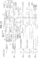
- the above type of ATM switchboard comprises an input port buffer 5, output port buffers 2-1 to 2-n (output port buffers 2-4 to 2-n are not illustrated), a buffer occupancy value measuring section 3, and a back-pressure outputting section 6.
- the input port buffer 5 comprises a separator 50 for each port, output port corresponding logical queues 51-1 to 51-n, a cell transmission control section 52, and a back-pressure receiving section 53.
- a case is assumed in which one traffic class is used in order to simplify the description.
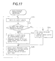
- FIG. 17 is a flow chart showing the back-pressure control by the back-pressure outputting section 6 in FIG. 16. The cell switching operation of a conventional ATM switch board is described below by referring to FIGS. 16 and 17.
- the destination output port of an ATM cell incoming from an input port 100 is identified by the separator 50 for each port in the input port buffer 5 and then stored in the proper output port corresponding to logical queues 51-1 to 51-n in accordance with the identified result.
- the cell transmission control section 52 controls transmission of the ATM cell in accordance with the rotation preferential control of cyclically carrying about a cell transmission right between the output port corresponding logical queues 51-1 and 51-n.
- ATM cells fetched from the output port corresponding logical queues 51-1 to 51-n selected in accordance with the processing by the cell transmission control section 52 are stored in the output port buffers 2-1 to 2-n corresponding to the destination output ports via an input port signal line 101 and a time-division multiplexing bus 102.
- the output port buffers 2-1 to 2-n cells are successively transmitted to output ports 103-1 to 103-n (output ports 103-4 to 103-n are not illustrated) starting with the first cell.
- the buffer occupancy value measuring section 3 observes the queue length of each of the output port buffers 2-1 to 2-n.
- the back-pressure outputting section 6 refers to the queue length information of each of the output port buffers 2-1 to 2-n of the buffer occupancy value measuring section 3 (step S31 in FIG. 17) and detects that the output port buffers 2-1 to 2-n brought under a congested state because queue lengths exceed a preset threshold are present (step S32 in FIG. 17), it transmits a transmission stop (STOP) signal 113 specifying a congested output port and a transmission restart (GO) signal 111 specifying output ports other than the congested output port to all input port buffers 5 (steps S33 and S35 in FIG. 17).
- STOP transmission stop
- GO transmission restart
- the back-pressure outputting section 6 detects the output port buffers 2-1 to 2-n brought under a congested state because queue lengths exceed a threshold are present (step S32 in FIG. 17), it transmits the transmission restart (GO) signal 111 specifying all output ports to all input port buffers 5 (steps S34 and S35 in FIG. 17).
- the back-pressure receiving section 53 receiving the transmission stop (STOP) signal 113 specifies an output port transmitting a back-pressure signal out of received back-pressure signal information and notifies the cell transmission control section 52 so as to inhibit transmission of cells from the output port corresponding logical queues 51-1 to 51-n corresponding to the output port.
- STOP transmission stop
- the back-pressure receiving section 53 transmits the transmission restart (GO) signal 111 specifying the output port and restarts the transfer of cells to those output ports to which transmission has been stopped.
- each input port buffer synchronously repeats transmission restart and transmission stop and therefore, the throughput from each input port to the same output port is uniform. Moreover, when the original traffic value bound for the same output port fluctuates between input ports, VCs (Virtual Channels) using the same output port may not be able to compensate the throughput at all even if they reserve bands.
- the transmission time for the next cell is computed whenever transmitting a cell.
- the control is performed by continuously comparing the cell transmission time with the present time and transmitting a cell when its transmission time is earlier than the present time, a state arises in which no cell can be transmitted from an input port buffer although no output port buffer is congested. Therefore, a problem arises as the use of the output port buffer is inefficient.
- a switch control circuit of an ATM switchboard for switching an ATM cell transferred in an asynchronous mode between an input port and an output port comprises an input port buffer and an output port buffer provided correspondingly to the input port and the output port respectively to perform ATM cell exchange between the input port and the output port; a back-pressure function for outputting any one of a transmission restart signal, transmission stop signal, and transmission control signal in accordance with the occupancy value of the output port buffer in order to prevent cells from being disused by the output port buffer; and cell transmission control means for performing control so as to transmit the ATM cell at a preset first rate to an output port for transmitting the ATM cell when the transmission restart signal is input from the back-pressure function correspondingly to the output port and transmit the ATM cell at a preset second rate to an output port for transmitting the ATM cell when the transmission control signal is input from the back pressure function correspondingly to the output port.
- a switch control method of an ATM switchboard for switching an ATM cell transferred in an asynchronous mode between an input port and an output port comprises the first step of outputting any one of a transmission restart signal, transmission stop signal, and transmission control signal in accordance with the occupancy value of the output port buffer in order to prevent cells in an output port buffer provided correspondingly to the output port from being lost and the second step of performing control so as to transmit the ATM cell at a preset first rate to an output port for transmitting the ATM cell when the transmission restart signal is input in the first step correspondingly to the output port and transmitting the ATM cell to an output port for transmitting the ATM cell at a preset second rate, when the transmission control signal is input in the first step correspondingly to the output port.
- the present invention is constituted so that a back pressure signal to be transferred between an input port buffer and an output port buffer uses such three types of signals as a transmission restart (GO) signal, transmission stop (STOP) signal, and transmission control (SHAPE) signal.
- a transmission restart (GO) signal transmission restart (GO) signal
- STOP transmission stop
- SHAPE transmission control
- an input port buffer transmits a cell to an output port currently outputting a transmission restart signal at a first rate (R1) and transmits a cell to an output port currently outputting a transmission control signal at a second rate (R2).
- the next cell transmission time is computed in accordance with the second rate (R2) whenever transmitting a cell from each logical queue by an input port buffer, a cell is only transmitted in accordance with a transmission time sequence while receiving a transmission restart signal, and a cell is transmitted in accordance with a transmission time sequence similarly to the above while receiving a transmission control signal.
- the transmission time is always compared with the present time so as to transmit a cell only when the transmission time is earlier than the present time.
- the traffic control is realized which controls the occurrence of congestion in an ATM switchboard and assures the throughput of VCs during the same output port.
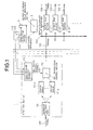
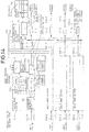
- FIG. 1 is a block diagram showing the structure of an embodiment of the present invention.
- the ATM switchboard of the embodiment of the present invention comprises an input port buffer 1, output port buffers 2-1 to 2-n (output port buffers 2-4 to 2-n are not illustrated), a buffer occupancy value measuring section 3, and a back-pressure outputting section 4.
- the input port buffer 1 comprises a separator 10 for each port, an output port corresponding logical queues 11-1 to 11-n, a cell transmission control section 12, and a back-pressure receiving section 13.
- the input port buffer 1 includes output port corresponding logical queues 11-1 to 11-n corresponding to output ports 103-1 to 103-n (output ports 103-4 to 103-n are not illustrated) respectively to make queuing possible for each of the output ports 103-1 to 103-n.
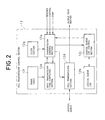
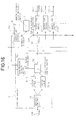
- FIG. 2 is a block diagram showing the structure of the cell transmission control section 12 in FIG. 1.
- the cell transmission control section 12 comprises a transmission control section 12a, a logical queue list 12b, a logical queue list control section 12c, a cell transmitting section 12d, a next transmission time computing section 12e, a band table 12f, and a clock section 12g.
- the input port buffer 1 identifies the destination output port of an ATM cell incoming from the input port 100 by the separator 10 for each port and stores the destination output port of the ATM cell in proper output port corresponding logical queues 11-1 to 11-n in accordance with the identified result.
- the cell transmission control section 12 transmits ATM cells from the output port corresponding logical queues 11-1 to 11-n and then, computes the next time for transmitting ATM cells from the same logical queues by the next transmission time computing section 12e, and has the logical queue list 12b in which logical queues to be transmitted are arranged in order of time.
- ATM cells fetched from the output port corresponding logical queues 11-1 to 11-n located at the head of the logical queue list 12b are stored in the output port buffers 2-1 to 2-n corresponding to their destination output ports via the input port signal line 101 and time-division multiplexing bus 102 from the sell transmitting section 12d of the cell transmission control section 12.
- the output port buffers 2-1 to 2-n successively transmit the ATM cells to the output ports 103-1 to 103-n starting with the first ATM cell.
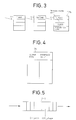
- FIG. 3 is an illustration showing an example of the logical queue list 12b of the cell transmission control section 12 in FIG. 1.
- the logical queue list 12b holds the position (first, second, or third), transmission time, class, and destination port of the logical queue on the list.
- the next transmission time computing section 12e of the cell transmission control section 12 transmits ATM cells from the output port corresponding logical queues 11-1 to 11-n respectively and then, computes the next transmission time for transmitting ATM cells from the same output port corresponding logical queues 11-l to 11-n.
- An example of the computation method is shown below.
- Tnext Tprev + 1/ ⁇ BWi
- the band BWi assigned to each connection is determined by call acceptance control before the connection is set so that the sum of assigned bands to which all connections are sent via a destination output port does not exceed the maximum band.
- FIG. 4 is an illustration showing an example of the information contents (buffer occupancy value table) of the buffer occupancy value measuring section 3 in FIG. 1.
- the occupancy value (queue length) of each of the output port buffers 2-1 to 2-n measured by the buffer occupancy value measuring section 3 is stored in a buffer occupancy value table 3a correspondingly to each of the output port buffers 2-1 to 2-n.
- FIG. 5 is an illustration showing an example of threshold setting in the output port buffer 2-1 in FIG. 1.
- a threshold Qth_shape for the back-pressure outputting section 4 to output a transmission control (SHAPE) signal 112 and a threshold Qth_stop for the back-pressure outputting section 4 to a transmission stop (STOP)signal 113 are set to the output port buffer 2-1.
- SHAPE transmission control
- STOP transmission stop
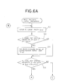
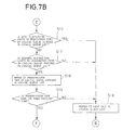
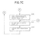
- FIGS. 6A and 6B are flow charts showing the back pressure control by the back-pressure outputting section 4 in FIG. 1 and FIGS. 7A, 7B and 7C are flow charts showing the cell transmission control by the cell transmission control section 12 in FIG. 1. While referring to FIGS. 1 to 7, the cell transmission control according to an embodiment of the present invention is described below. To simplify the description, it is assumed that only one traffic class is present.
- the input port buffer 1 identifies the destination output ports of the ATM cells incoming from the input port 100 by the separator 10 for each port and stores them in proper output port corresponding logical queues 11-1 to 11-n in accordance with the identified results.
- the cell transmission control section 12 transmits ATM cells from the output port logical queues 11-1 to 11-n and then, computes the next time for transmitting ATM cells from the same logical queues using the next transmission time computing section 12e and has the logical queue list 12b in which logical queues to be transmitted are arranged in order of transmission time.
- the ATM cells fetched from the output port corresponding logical queues 11-1 to 11-n located at the head of the logical queue list 12b are stored in the output port buffers 2-1 to 2-n corresponding to their destination output ports from the cell transmitting section 12d of the cell transmission control section 12 via the input-port signal line 101 and the time-division multiplexing bus 102.
- the output port buffers 2-1 to 2-n successively transmit the ATM cells to the output ports 103-1 to 103-n starting with the first ATM cell.
- the buffer occupancy value measuring section 3 measures the occupancy value (queue length) of each of the output port buffers 2-1 to 2-n and stores the measured queue lengths in the buffer occupancy value table 3a correspondingly to the output port buffers 2-1 to 2-n respectively.
- the back-pressure outputting section 4 refers to queue lengths Qout in the buffer occupancy value table 3a of the buffer occupancy value measuring section 3 (step S1 in FIG. 6A) to judge whether the output port buffers 2-1 to 2-n having a queue length Qout equal to or less than the threshold Qth_shape prepared for the output ports 103-1 to 103-n respectively are present (step S2 in FIG. 6A).
- the back-pressure outputting section 4 uses back pressure signals for the corresponding output ports 103-1 to 103-n as the transmission restart (GO) signal 111 (step S3 in FIG. 6A).
- the back-pressure outputting section 4 judges whether the output port buffers 2-1 to 2-n having a queue length Qout between the threshold Qth_shape and the threshold Qth_stop are present (step S4 in FIG. 6A).
- the back-pressure outputting section 4 uses back pressure signals for the corresponding output ports 103-1 to 103-n as the transmission control (SHAPE) signal 112 (step S5 in FIG. 6B).
- SHAPE transmission control
- the back-pressure outputting section 4 judges whether the output port buffers 2-1 to 2-n having a queue length Qout equal to or more than the threshold Qth_stop are present (step S6 in FIG. 6B).
- the back-pressure outputting section 4 uses back pressure signals for the corresponding output ports 103-1 to 103-n as the transmission stop (STOP) signal 113 (step S7 in FIG. 6B).
- the back-pressure outputting section 4 outputs the back pressure signals corresponding to the output ports 103-1 to 103-n to all the input port buffers 1 (step S8 in FIG. 6B).
- the section 13 When the back-pressure receiving section 13 of the input port buffer 1 receives back pressure signals from the back-pressure outputting section 4, the section 13 stores the back pressure signals in a back-pressure-signal receiving state (not illustrated) by making them correspond to the output ports 103-1 to 103-n and communicates instructions (restart, control, and stop) corresponding to the back pressure signals to the cell transmission control section 12.
- the cell transmission control section 12 refers to the head of the logical queue list 12b (step S11 in FIG. 7A) and refers to the instruction from the back-pressure receiving section 13 corresponding to the destination port of the logical queue entered in the head of the logical queue list 12b (step S12 in FIG. 7A).
- the cell transmission control section 12 transmits the ATM cell of the logical queue entered in the head of the logical queue list 12 (step S14 in FIG. 7A). In this case, the cell transmission control section 12 does not compare the transmission time or the ATM cell with the present time.
- the cell transmission control section 12 refers to the next one in the logical queue list 12b (step S16 in FIG. 7B).
- the cell transmission control section 12 when the instruction from the back-pressure receiving section 13 is a stop instruction, the cell transmission control section 12 completely stops the transmission of ATM cells to their destination port and refers to the next one in the logical queue list 12b. Moreover, when the instruction from the back-pressure receiving section 13 is not any one of a restart instruction, stop instruction, and control instruction, the cell transmission control section 12 decides the instruction as an error and refers to the next one in the logical queue list 12b.
- the cell transmission control section 12 refers to the transmission time of the logical queue entered in the head of the logical queue list 12b (step S18 in FIG. 7B) and transmits the ATM cell only when the transmission time is earlier than the present time sent from the clock section 12g (step S19 in FIG. 7B and step S20 in FIG. 7C).
- the cell transmission control section 12 refers to the next one in the logical queue list 12b (step S16 in FIG. 7B).
- the ATM switchboard of an embodiment of the present invention makes it possible to improve the utilization efficiency of the output port buffers 2-1 to 2-n by making the cell transmission control by each input port buffer 1 independent of the present time and thereby excessively transmitting ATM cells.
- the output port buffers 2-1 to 2-n are not further congested and therefore, it is possible to greatly decrease the output frequency of the transmission stop (STOP) signal 113.
- STOP transmission stop
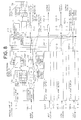
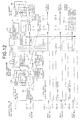
- FIGS. 8 and 9 are state diagrams for explaining a processing procedure by the ATM switchboard shown in FIG. 1 when the queue length Qout of an output port #4 is equal to or less than a threshold Qth_shape for generating a transmission control (SHAPE) signal and FIGS. 10 and 11 are state diagrams for explaining a processing procedure by the ATM switchboard shown in FIG. 1 when a queue length Qout of an output port #4 is equal to or more than a threshold Qth_shape for generating a transmission control (SHAPE) signal and equal to or less than a threshold Qth_stop for generating a transmission stop (STOP) signal.
- SHAPE transmission control
- FIGS. 12 and 13 are state diagrams for explaining a processing procedure by the ATM switchboard shown in FIG. 1 when a queue length Qout of an output port #4 is equal to or more than a threshold Qth_shape for generating a transmission control (SHAPE) signal and equal to or less than a threshold Qth_stop for generating a transmission stop (STOP) signal
- FIGS. 14 and 15 are state diagrams for explaining a processing procedure by the ATM switchboard shown in FIG. 1 when a queue length Qout of an output port #4 is equal to or more than a threshold Qth_stop for generating a transmission stop (STOP) signal.
- SHAPE transmission control
- STOP transmission stop
- the ATM switchboard of an embodiment of the present invention including input ports 100-1 to 100-4 and output ports 103-1 to 103-4 uses 40 cells for the threshold Qth_shape for outputting the transmission control(SHAPE) signal 112 and 80 cells for the threshold Qth_stop for outputting the transmission stop (STOP) signal 113 from the output port buffers 2-1 to 2-n respectively.
- connections are used from the input ports (#1 to #4) 100-1 to 100-4 to the output port (#4) 103-4 one each.
- the input ports 1-2 and 1-4 have the same structure as the input port 1-1 and the above band information is previously stored in the band table 12f of the cell transmission control section 12.
- the cell transmission control section 12 fetches an ATM cell from a logical queue in which VC1 is stored without comparing a transmission time with the present time and stores the ATM cell in the destination output port buffer 2-4 via the time division bus 102.
- next transmission time Tnext of a logical queue addressed to the output port (#4) present at the head of the logical queue list 12b is computed by the next transmission time computing section 12e in accordance with the expression (1). That is, the next transmission time Tnext is obtained as shown below.
- the cell transmission control section 12 instructs the logical queue list control section 12c to re-sort data in the logical queue list 12b in order of transmission time in accordance with the next transmission time Tnext computed by the next transmission time computing section 12e.
- the cell transmission control section 12 compares a transmission time with the present time.
- the cell transmission control section 12 does not transmit any ATM cell to the output port (#4) from the logical queue but instead it checks the next entry in the logical queue list 12b.
- the cell transmission control section 12 compares a transmission time with the present time.
- the cell transmission control section 12 transmits an ATM cell to the output port (#4) from the logical queue and then, computes the next transmission time and re-sorts data in the logical queue list 12b in order of transmission time.
- the cell transmission control section 12 does not transmit any ATM cell from the logical queue to the output port (#4) but it checks the next entry in the logical queue list 12b.
- the transmission control (SHAPE) signal 112 is output and the cell transmission control by each of the input port buffers 1 and 1-1 to 1-4 is strictly compared with the present time so that the total number of cells addressed to the output ports 103-1 to 103-n corresponding to the congested output port buffers 2-1 to 2-n does not exceed the maximum band.
- the output port buffers 2-1 to 2-n are not further congested and thus, it is possible to greatly decrease the output frequency of the transmission stop (STOP) signal 113.
- a switch control circuit of an ATM switchboard for switching ATM cells transferred in an asynchronous mode between an input port and an output port realizes the traffic control for controlling occurrence of congestion in the ATM switchboard ; assures the throughput of VCs using the same output port by using an input port buffer and an output port buffer for exchanging ATM cells between the input port and the output port; outputs any one of a transmission restart signal, transmission stop signal, and transmission control signal from a back-pressure function in accordance with an output port buffer occupancy value in order to prevent cells from being disused in the output port buffer; and performs traffic control so as to transmit ATM cells at a preset first rate to the output port when a transmission restart signal is input from the back pressure function correspondingly to the output port for transmitting ATM cells; and so as to transmit ATM cells at a preset second rate to the output port when a transmission control signal is input from the back pressure function correspondingly to an output port for transmitting ATM cells.
- Traffic control for controlling the occurrence of congestion in an ATM switchboard and assuring the throughput of VCs using the same ouput port.
- a buffer occupancy value measuring section measures the queue length of each output port buffer and stores the data in a buffer occupancy value table.
- a back-pressure outputting section outputs a transmission restart signal when a queue length in the buffer occupancy table is equal to or less than a first threshold, a transmission control signal when the queue length is between the first threshold and a second threshold, and a transmission stop signal when the queue length is equal to or more than the second threshold as the appropriate back pressure signal.
- a cell transmission control section transmits an ATM cell without comparing the cell transmission time with the present time if the instruction of a back pressure signal corresponding to a destination port indicates "restart" and transmits an ATM cell only if the transmission time is earlier than the present time if the instruction indicates "control".
Abstract
Description

Claims (24)
- A switch control circuit of an ATM switchboard for switching ATM cells transferred in an asynchronous mode between an input port and an output port, said circuit comprising an input port buffer and an output port buffer provided correspondingly to said input port and said output port respectively to perform ATM cell exchange between said input port and said output port; a back-pressure function for outputting any one of a transmission restart signal, transmission stop signal, and transmission control signal in accordance with said occupancy value of said output port buffer in order to prevent cells from being unused by said output port buffer; and cell transmission control means to transmit said ATM cells at a preset first rate to an output port, when said transmission restart signal is input from said back-pressure function corresponding to said output port and to transmit said ATM cells at a preset second rate to an output port when said transmission control signal is input from said back pressure function corresponding to said output port.
- The switch control circuit according to claim 1, wherein said back pressure function is constituted so as to output any one of said transmission restart signal, said transmission stop signal, and said transmission control signal correspondingly to said output port.
- The switch control circuit according to claim 1, wherein said back pressure function is constituted so as to output said transmission restart signal when the occupancy value of said output port buffer is less than a preset first threshold, said transmission control signal when the occupancy value of said output port buffer is between said first threshold and a preset second threshold, and said transmission stop signal when the occupancy value of said output port buffer is equal to or more than said second threshold.
- The switch control circuit according to claim 1, wherein said cell transmission control means includes comparison means for comparing the present time with a scheduled transmission time computed in accordance with said second rate when transmitting said ATM cells at said second rate and means for performing control by said comparison means so as to transmit said ATM cells when said scheduled transmission time is earlier than said present time.
- The switch control circuit according to claim 1, wherein said cell transmission control means includes means for performing control so as to transmit said ATM cells at the maximum rate in order of scheduled transmission time computed in accordance with said second rate independently of the present time when transmitting said ATM cells at said first rate.
- The switch control circuit according to claim 1, wherein said cell transmission control means includes time computing means for computing a scheduled transmission time of an ATM cell.
- The switch control circuit according to claim 1, wherein said cell transmission control means has a list in which said ATM cells to be transmitted are arranged in order of scheduled transmission time and in which said cell transmission control controls the transmission of an ATM cell at the head of the list in accordance with a signal obtained from said back pressure function.
- The switch control circuit according to claim 3, wherein said back pressure function first checks whether said output port buffer has an occupancy value less than said first threshold, then checks whether said output port buffer has an occupancy value between said first threshold and said second threshold, and finally checks whether said output port buffer has an occupancy value equal to or more than said second threshold.
- The switch control circuit according to claim 8, wherein said back pressure function outputs a transmission stop signal corresponding to said output port buffer to said cell transmission control means when said output port buffer has an occupancy value equal to or more than the said second threshold and thereafter, outputs any one of said transmission restart signal, said transmission stop signal, and said transmission control signal corresponding to each output port buffer again.
- The switch control circuit according to claim 8, wherein said back pressure function outputs any one of said transmission restart signal, said transmission stop signal, and said transmission control signal corresponding to each output port buffer again when not one of said output buffers has an occupancy value equal to or more than said second threshold.
- The switch control circuit according to claim 7, wherein said transmission control means stop the transmission of said ATM cells and controls the transmission of an ATM cell next located in said list in accordance with a signal obtained from said back pressure function when said transmission stop signal is input to said cell transmission control means by said back pressure function.
- The switch control circuit according to claim 7, wherein said cell transmission control means decides that a case in which said transmission restart signal, said transmission stop signal, or said transmission control signal is not input to said cell transmission control means by said back pressure function is an error and controls the transmission of the next ATM cell in said list in accordance with a signal obtained from said back pressure function.
- A switch control method for an ATM switchboard for switching an ATM cell transferred in an asynchronous mode between an input port and an output port, the method comprising the first step of outputting any one of a transmission restart signal, transmission stop signal, and transmission control signal in accordance with the occupancy value of said output port buffer in order to prevent cells in said output port buffer from being discarded and the second step of performing control so as to transmit said ATM cell at a preset first rate to an output port when said transmission restart signal is input in said first step and transmitting said ATM cell to an output port at a preset second rate when said transmission control signal is input in said first step.
- A traffic control method for controlling congestion in an ATM switchboard, comprising:measuring the queue length of each output port buffer and storing the buffer occupancy value in a buffer occupancy table;outputting a back-pressure control signal wherein said back-pressure control signal is a transmission restart signal when the buffer occupancy value is equal to or less than a threshold, is a transmission control signal when the buffer value is between the first threshold and a second threshold, and is a transmission stop signal when the buffer value exceeds a second threshold value;transmitting a cell without examining its transmission scheduled time if the back-pressure signal indicates "restart" for the destination port; andtransmitting a cell only at its scheduled transmission time if the back-pressure signal indicates "control".
- The switch control method according to claim 13, wherein said first step is constituted so as to output said transmission restart signal when the occupancy value of said output port buffer is less than a preset first threshold, said transmission control signal when the occupancy value of said output port buffer is between said first threshold and a preset second threshold, and said transmission stop signal when the occupancy value of said output port buffer is equal to or more than said second threshold.
- The switch control method according to claim 13, wherein said second step includes comparing the present time with a schedule transmission time computed in accordance with said second rate when transmitting said ATM cells at said second rate and performing control so as to transmit said ATM cells when said scheduled transmission time is earlier than said present time in said third step.
- The switch control method according to claim 13, wherein said second step includes transmitting said ATM cells at the highest rate of scheduled transmission time computed in accordance with said second rate independently of the present time when transmitting said ATM cells at said first rate.
- The switch control method according to claim 13, wherein said second step includes transmitting said ATM cells and thereafter computing the scheduled transmission time of the next ATM cell to be transmitted.
- The switch control method according to claim 13, wherein said second step includes generating a list by arranging said ATM cells to be transmitted in order of scheduled transmission time and the eighth step of controlling the transmission of an ATM cell located at the head of the list in accordance with a signal obtained from said first step.
- The switch control method according to claim 13, wherein said first step first includes checking whether said output port buffer has an occupancy value less than said first threshold, then checks whether said output port buffer has an occupancy value between said first threshold and said second threshold, and finally checks whether said output port buffer has an occupancy value equal to or more than said second threshold.
- The switch control method according to claim 20, wherein said first step includes outputting a transmission stop signal corresponding to said output port buffer when said output port buffer has - an occupancy value equal to or more than said second threshold and thereafter, outputs any one of said transmission restart signal, said transmission stop signal, and said transmission control signal corresponding to each output port buffer again.
- The switch control method according to claim 20, wherein said first step includes outputting again any one of said transmission restart signal, said transmission stop signal, and said transmission control signal corresponding to each output port buffer when not one of said output buffers has an occupancy value equal to or more than said second threshold.
- The switch control method according to claim 19, wherein said second step includes stopping the transmission of said ATM cells when said transmission stop signal is input and controls the transmission of an ATM cell next located in said list in accordance with a signal obtained from said first step.
- The switch control method according to claim 19, wherein said second step decides that a case in which said transmission restart signal, said transmission stop signal, or said transmission control signal is not input is an error and controls the transmission of the next ATM cell in said list in accordance with a signal obtained from said first step.
Applications Claiming Priority (3)
| Application Number | Priority Date | Filing Date | Title |
|---|---|---|---|
| JP30074496A JP3123447B2 (en) | 1996-11-13 | 1996-11-13 | Switch control circuit of ATM exchange |
| JP30074496 | 1996-11-13 | ||
| JP300744/96 | 1996-11-13 |
Publications (3)
| Publication Number | Publication Date |
|---|---|
| EP0853441A2 true EP0853441A2 (en) | 1998-07-15 |
| EP0853441A3 EP0853441A3 (en) | 1999-06-16 |
| EP0853441B1 EP0853441B1 (en) | 2006-10-04 |
Family
ID=17888588
Family Applications (1)
| Application Number | Title | Priority Date | Filing Date |
|---|---|---|---|
| EP19970309154 Expired - Lifetime EP0853441B1 (en) | 1996-11-13 | 1997-11-13 | Switch control circuit and switch control method of ATM switchboard |
Country Status (5)
| Country | Link |
|---|---|
| US (1) | US6122251A (en) |
| EP (1) | EP0853441B1 (en) |
| JP (1) | JP3123447B2 (en) |
| AU (1) | AU734413B2 (en) |
| CA (1) | CA2220889C (en) |
Cited By (43)
| Publication number | Priority date | Publication date | Assignee | Title |
|---|---|---|---|---|
| GB2344030A (en) * | 1998-11-17 | 2000-05-24 | 3Com Technologies Ltd | Credit-based scheme for packet communication system. |
| WO2001002965A2 (en) * | 1999-06-30 | 2001-01-11 | Broadcom Corporation | Memory management unit for a network switch |
| US6430188B1 (en) | 1998-07-08 | 2002-08-06 | Broadcom Corporation | Unified table for L2, L3, L4, switching and filtering |
| GB2336076B (en) * | 1998-04-03 | 2003-01-15 | 3Com Technologies Ltd | Network device |
| US6535510B2 (en) | 2000-06-19 | 2003-03-18 | Broadcom Corporation | Switch fabric with path redundancy |
| US6678678B2 (en) | 2000-03-09 | 2004-01-13 | Braodcom Corporation | Method and apparatus for high speed table search |
| US6826561B2 (en) | 2000-05-22 | 2004-11-30 | Broadcom Corporation | Method and apparatus for performing a binary search on an expanded tree |
| US6839349B2 (en) | 1999-12-07 | 2005-01-04 | Broadcom Corporation | Mirroring in a stacked network switch configuration |
| US6851008B2 (en) | 2002-03-06 | 2005-02-01 | Broadcom Corporation | Adaptive flow control method and apparatus |
| US6851000B2 (en) | 2000-10-03 | 2005-02-01 | Broadcom Corporation | Switch having flow control management |
| US6850542B2 (en) | 2000-11-14 | 2005-02-01 | Broadcom Corporation | Linked network switch configuration |
| US6859454B1 (en) | 1999-06-30 | 2005-02-22 | Broadcom Corporation | Network switch with high-speed serializing/deserializing hazard-free double data rate switching |
| US6988177B2 (en) | 2000-10-03 | 2006-01-17 | Broadcom Corporation | Switch memory management using a linked list structure |
| US6999455B2 (en) | 2000-07-25 | 2006-02-14 | Broadcom Corporation | Hardware assist for address learning |
| US7009973B2 (en) | 2000-02-28 | 2006-03-07 | Broadcom Corporation | Switch using a segmented ring |
| US7009968B2 (en) | 2000-06-09 | 2006-03-07 | Broadcom Corporation | Gigabit switch supporting improved layer 3 switching |
| US7020166B2 (en) | 2000-10-03 | 2006-03-28 | Broadcom Corporation | Switch transferring data using data encapsulation and decapsulation |
| US7031302B1 (en) | 1999-05-21 | 2006-04-18 | Broadcom Corporation | High-speed stats gathering in a network switch |
| US7035286B2 (en) | 2000-11-14 | 2006-04-25 | Broadcom Corporation | Linked network switch configuration |
| US7035255B2 (en) | 2000-11-14 | 2006-04-25 | Broadcom Corporation | Linked network switch configuration |
| US7061868B1 (en) | 2000-10-25 | 2006-06-13 | Switchcore, Ab | Method for flow control in a switch and a switch controlled thereby |
| US7082133B1 (en) | 1999-09-03 | 2006-07-25 | Broadcom Corporation | Apparatus and method for enabling voice over IP support for a network switch |
| US7103053B2 (en) | 2000-05-03 | 2006-09-05 | Broadcom Corporation | Gigabit switch on chip architecture |
| US7120117B1 (en) | 2000-08-29 | 2006-10-10 | Broadcom Corporation | Starvation free flow control in a shared memory switching device |
| US7120155B2 (en) | 2000-10-03 | 2006-10-10 | Broadcom Corporation | Switch having virtual shared memory |
| US7126947B2 (en) | 2000-06-23 | 2006-10-24 | Broadcom Corporation | Switch having external address resolution interface |
| US7131001B1 (en) | 1999-10-29 | 2006-10-31 | Broadcom Corporation | Apparatus and method for secure filed upgradability with hard wired public key |
| US7143294B1 (en) | 1999-10-29 | 2006-11-28 | Broadcom Corporation | Apparatus and method for secure field upgradability with unpredictable ciphertext |
| US7227862B2 (en) | 2000-09-20 | 2007-06-05 | Broadcom Corporation | Network switch having port blocking capability |
| US7274705B2 (en) | 2000-10-03 | 2007-09-25 | Broadcom Corporation | Method and apparatus for reducing clock speed and power consumption |
| US7315552B2 (en) | 1999-06-30 | 2008-01-01 | Broadcom Corporation | Frame forwarding in a switch fabric |
| US7355970B2 (en) | 2001-10-05 | 2008-04-08 | Broadcom Corporation | Method and apparatus for enabling access on a network switch |
| US7366208B2 (en) | 1999-11-16 | 2008-04-29 | Broadcom | Network switch with high-speed serializing/deserializing hazard-free double data rate switch |
| US7420977B2 (en) | 2000-10-03 | 2008-09-02 | Broadcom Corporation | Method and apparatus of inter-chip bus shared by message passing and memory access |
| US7424012B2 (en) | 2000-11-14 | 2008-09-09 | Broadcom Corporation | Linked network switch configuration |
| US7539134B1 (en) | 1999-11-16 | 2009-05-26 | Broadcom Corporation | High speed flow control methodology |
| US7593953B1 (en) | 1999-11-18 | 2009-09-22 | Broadcom Corporation | Table lookup mechanism for address resolution |
| US7593403B2 (en) | 1999-05-21 | 2009-09-22 | Broadcom Corporation | Stacked network switch configuration |
| US7720055B2 (en) | 1999-03-17 | 2010-05-18 | Broadcom Corporation | Method for handling IP multicast packets in network switch |
| US20140241160A1 (en) * | 2013-02-22 | 2014-08-28 | Broadcom Corporation | Scalable, Low Latency, Deep Buffered Switch Architecture |
| US9985899B2 (en) | 2013-03-28 | 2018-05-29 | British Telecommunications Public Limited Company | Re-marking of packets for queue control |
| US10469393B1 (en) | 2015-08-06 | 2019-11-05 | British Telecommunications Public Limited Company | Data packet network |
| US10645016B2 (en) | 2015-08-06 | 2020-05-05 | British Telecommunications Public Limited Company | Data packet network |
Families Citing this family (43)
| Publication number | Priority date | Publication date | Assignee | Title |
|---|---|---|---|---|
| DK174882B1 (en) * | 1996-04-12 | 2004-01-19 | Tellabs Denmark As | Method and network element for transmitting data packets in a telephony transmission network |
| US6747954B1 (en) * | 1997-12-19 | 2004-06-08 | Telefonaktiebolaget Lm Ericsson (Publ) | Asynchronous transfer mode switch providing pollstate status information |
| US6865154B1 (en) | 1998-01-12 | 2005-03-08 | Enterasys Networks, Inc. | Method and apparatus for providing bandwidth and delay guarantees in combined input-output buffered crossbar switches that implement work-conserving arbitration algorithms |
| US6563837B2 (en) * | 1998-02-10 | 2003-05-13 | Enterasys Networks, Inc. | Method and apparatus for providing work-conserving properties in a non-blocking switch with limited speedup independent of switch size |
| US6934253B2 (en) * | 1998-01-14 | 2005-08-23 | Alcatel | ATM switch with rate-limiting congestion control |
| CN1214689C (en) | 1998-06-19 | 2005-08-10 | 杜松网络公司 | Device for performing IP forwarding and ATM switching |
| US6980543B1 (en) * | 1998-06-19 | 2005-12-27 | Juniper Networks, Inc. | Interconnect network for operation within a communication node |
| JP2000261438A (en) * | 1999-03-08 | 2000-09-22 | Sony Corp | Frame data exchange and its method |
| US6628610B1 (en) * | 1999-06-28 | 2003-09-30 | Cisco Technology, Inc. | Methods and apparatus for managing a flow of packets using change and reply signals |
| US6983350B1 (en) | 1999-08-31 | 2006-01-03 | Intel Corporation | SDRAM controller for parallel processor architecture |
| US6859435B1 (en) * | 1999-10-13 | 2005-02-22 | Lucent Technologies Inc. | Prevention of deadlocks and livelocks in lossless, backpressured packet networks |
| GB2356104B (en) * | 1999-11-04 | 2001-10-10 | 3Com Corp | Network switch including bandwidth controller |
| US6657960B1 (en) * | 1999-11-23 | 2003-12-02 | International Business Machines Corporation | Method and system for providing differentiated services in computer networks |
| US6667976B1 (en) * | 1999-12-09 | 2003-12-23 | Lucent Technologies Inc. | Fuzzycast service in switches |
| US6532509B1 (en) | 1999-12-22 | 2003-03-11 | Intel Corporation | Arbitrating command requests in a parallel multi-threaded processing system |
| US6694380B1 (en) | 1999-12-27 | 2004-02-17 | Intel Corporation | Mapping requests from a processing unit that uses memory-mapped input-output space |
| KR20010058256A (en) * | 1999-12-27 | 2001-07-05 | 오길록 | Method of Network Throughput Improvements Using Packet Discarding Algorithm with Two Thresholds |
| US6661794B1 (en) | 1999-12-29 | 2003-12-09 | Intel Corporation | Method and apparatus for gigabit packet assignment for multithreaded packet processing |
| US6771601B1 (en) * | 2000-01-31 | 2004-08-03 | International Business Machines Corporation | Network switch having source port queuing and methods, systems and computer program products for flow level congestion control suitable for use with a network switch having source port queuing |
| ATE285647T1 (en) * | 2000-06-09 | 2005-01-15 | Nokia Corp | METHOD AND SYSTEM FOR SENDING AND/OR RECEIVING INFORMATION BETWEEN NETWORK ELEMENTS |
| JP3646638B2 (en) * | 2000-09-06 | 2005-05-11 | 日本電気株式会社 | Packet switching apparatus and switch control method used therefor |
| GB0031535D0 (en) * | 2000-12-22 | 2001-02-07 | Nokia Networks Oy | Traffic congestion |
| US7289523B2 (en) * | 2001-09-13 | 2007-10-30 | International Business Machines Corporation | Data packet switch and method of operating same |
| US8145787B1 (en) * | 2001-10-16 | 2012-03-27 | Cisco Technology, Inc. | Adaptive bandwidth utilization over fabric links |
| US7464180B1 (en) | 2001-10-16 | 2008-12-09 | Cisco Technology, Inc. | Prioritization and preemption of data frames over a switching fabric |
| US6956861B2 (en) * | 2002-04-16 | 2005-10-18 | Interactics Holdings, Llc | Controlled shared memory smart switch system |
| US20030206550A1 (en) * | 2002-04-30 | 2003-11-06 | Transwitch Corporation | Methods and apparatus for increasing the number of UTOPIA ports in an ATM device |
| EP1504272A2 (en) * | 2002-04-30 | 2005-02-09 | Transwitch Corporation | An atm device incorporating methods and apparatus for increasing the number of utopia ports and method and apparatus for avoiding head of line blocking |
| US6765867B2 (en) * | 2002-04-30 | 2004-07-20 | Transwitch Corporation | Method and apparatus for avoiding head of line blocking in an ATM (asynchronous transfer mode) device |
| US7433307B2 (en) * | 2002-11-05 | 2008-10-07 | Intel Corporation | Flow control in a network environment |
| JP4337375B2 (en) * | 2003-03-14 | 2009-09-30 | 株式会社デンソー | Information distribution server, receiving terminal, information distribution system, reservation terminal, and reservation server |
| JP2006094304A (en) * | 2004-09-27 | 2006-04-06 | Nec Commun Syst Ltd | Transmission band control method and transmission band control system |
| JP2007053564A (en) * | 2005-08-17 | 2007-03-01 | Fujitsu Ltd | Network switching device |
| US7544105B2 (en) * | 2005-08-23 | 2009-06-09 | Utilx Corporation | Cable and cable connection assembly |
| US8144719B2 (en) * | 2005-10-25 | 2012-03-27 | Broadbus Technologies, Inc. | Methods and system to manage data traffic |
| JP5158511B2 (en) * | 2008-12-15 | 2013-03-06 | 株式会社リコー | Wireless LAN communication network system, wireless LAN communication network system management program, and computer-readable storage medium storing wireless LAN communication network system management program |
| JP5233775B2 (en) | 2009-03-19 | 2013-07-10 | 富士通株式会社 | Packet transmission apparatus, line interface unit, and packet transmission apparatus control method |
| US8885657B2 (en) * | 2009-11-06 | 2014-11-11 | Brocade Communications Systems, Inc. | Automatic switch port selection |
| US8593964B1 (en) | 2009-11-06 | 2013-11-26 | Brocade Communications Systems, Inc. | Method and system for traffic management |
| US8891368B2 (en) * | 2009-11-06 | 2014-11-18 | Brocade Communications Systems, Inc. | Presentation of a selected port |
| US9391849B2 (en) * | 2009-11-06 | 2016-07-12 | Brocade Communications Systems, Inc. | Back pressure remediation |
| US8644139B2 (en) * | 2010-04-26 | 2014-02-04 | International Business Machines Corporation | Priority based flow control within a virtual distributed bridge environment |
| US9501439B1 (en) | 2016-01-19 | 2016-11-22 | International Business Machines Corporation | Communicating in an integrated circuit using hardware-managed virtual channels |
Citations (3)
| Publication number | Priority date | Publication date | Assignee | Title |
|---|---|---|---|---|
| EP0603916A2 (en) * | 1992-12-25 | 1994-06-29 | Nec Corporation | Packet switching system using idle/busy status of output buffers |
| EP0661851A2 (en) * | 1993-12-22 | 1995-07-05 | Nec Corporation | Congestion control method in ATM network |
| EP0706297A1 (en) * | 1994-10-07 | 1996-04-10 | International Business Machines Corporation | Method for operating traffic congestion control in a data communication network and system for implementing said method |
Family Cites Families (7)
| Publication number | Priority date | Publication date | Assignee | Title |
|---|---|---|---|---|
| US5901140A (en) * | 1993-10-23 | 1999-05-04 | International Business Machines Corporation | Selective congestion control mechanism for information networks |
| US5392280A (en) * | 1994-04-07 | 1995-02-21 | Mitsubishi Electric Research Laboratories, Inc. | Data transmission system and scheduling protocol for connection-oriented packet or cell switching networks |
| GB2288947B (en) * | 1994-04-20 | 1999-01-06 | Roke Manor Research | Improvements in or relating to ATM communication systems |
| JP3625302B2 (en) * | 1994-07-19 | 2005-03-02 | 株式会社東芝 | Data delivery apparatus and method for network system |
| ES2137296T3 (en) * | 1994-09-28 | 1999-12-16 | Siemens Ag | ATM COMMUNICATION SYSTEM FOR STATISTICAL CELL MULTIPLEXION. |
| EP0717532A1 (en) * | 1994-12-13 | 1996-06-19 | International Business Machines Corporation | Dynamic fair queuing to support best effort traffic in an ATM network |
| JP3315588B2 (en) * | 1996-05-16 | 2002-08-19 | 株式会社日立製作所 | ATM switch for traffic flow control |
-
1996
- 1996-11-13 JP JP30074496A patent/JP3123447B2/en not_active Expired - Fee Related
-
1997
- 1997-11-12 AU AU45143/97A patent/AU734413B2/en not_active Ceased
- 1997-11-12 CA CA 2220889 patent/CA2220889C/en not_active Expired - Fee Related
- 1997-11-12 US US08/968,568 patent/US6122251A/en not_active Expired - Lifetime
- 1997-11-13 EP EP19970309154 patent/EP0853441B1/en not_active Expired - Lifetime
Patent Citations (3)
| Publication number | Priority date | Publication date | Assignee | Title |
|---|---|---|---|---|
| EP0603916A2 (en) * | 1992-12-25 | 1994-06-29 | Nec Corporation | Packet switching system using idle/busy status of output buffers |
| EP0661851A2 (en) * | 1993-12-22 | 1995-07-05 | Nec Corporation | Congestion control method in ATM network |
| EP0706297A1 (en) * | 1994-10-07 | 1996-04-10 | International Business Machines Corporation | Method for operating traffic congestion control in a data communication network and system for implementing said method |
Non-Patent Citations (1)
| Title |
|---|
| MARK B L ET AL: "LARGE CAPACITY MULTICLASS ATM CORE SWITCH ARCHITECTURE" ISS '97. WORLD TELECOMMUNICATIONS CONGRESS. (INTERNATIONAL SWITCHIN SYMPOSIUM), GLOBAL NETWORK EVOLUTION: CONVERGENCE OR COLLISION? TORONTO, SEPT. 21 - 26, 1997, vol. 1, 21 September 1997, ABE S ET AL, pages 417-423, XP000720547 * |
Cited By (79)
| Publication number | Priority date | Publication date | Assignee | Title |
|---|---|---|---|---|
| GB2336076B (en) * | 1998-04-03 | 2003-01-15 | 3Com Technologies Ltd | Network device |
| US6430188B1 (en) | 1998-07-08 | 2002-08-06 | Broadcom Corporation | Unified table for L2, L3, L4, switching and filtering |
| US7103055B2 (en) | 1998-07-08 | 2006-09-05 | Broadcom Corporation | Unified table for L2, L3, L4, switching and filtering |
| GB2344030A (en) * | 1998-11-17 | 2000-05-24 | 3Com Technologies Ltd | Credit-based scheme for packet communication system. |
| US6442162B1 (en) | 1998-11-17 | 2002-08-27 | 3Com Technologies | Credit-based scheme for high performance communication between devices in a packet-based communication system |
| GB2344030B (en) * | 1998-11-17 | 2003-06-04 | 3Com Technologies Ltd | Credit-based scheme for high performance communication between devices in a packet-based communication system |
| US8411574B2 (en) | 1999-03-05 | 2013-04-02 | Broadcom Corporation | Starvation free flow control in a shared memory switching device |
| US7782891B2 (en) | 1999-03-17 | 2010-08-24 | Broadcom Corporation | Network switch memory interface configuration |
| US7720055B2 (en) | 1999-03-17 | 2010-05-18 | Broadcom Corporation | Method for handling IP multicast packets in network switch |
| US7593403B2 (en) | 1999-05-21 | 2009-09-22 | Broadcom Corporation | Stacked network switch configuration |
| US7031302B1 (en) | 1999-05-21 | 2006-04-18 | Broadcom Corporation | High-speed stats gathering in a network switch |
| US6859454B1 (en) | 1999-06-30 | 2005-02-22 | Broadcom Corporation | Network switch with high-speed serializing/deserializing hazard-free double data rate switching |
| US7315552B2 (en) | 1999-06-30 | 2008-01-01 | Broadcom Corporation | Frame forwarding in a switch fabric |
| WO2001002965A3 (en) * | 1999-06-30 | 2001-08-30 | Broadcom Corp | Memory management unit for a network switch |
| WO2001002965A2 (en) * | 1999-06-30 | 2001-01-11 | Broadcom Corporation | Memory management unit for a network switch |
| US7082133B1 (en) | 1999-09-03 | 2006-07-25 | Broadcom Corporation | Apparatus and method for enabling voice over IP support for a network switch |
| US7577148B2 (en) | 1999-09-03 | 2009-08-18 | Broadcom Corporation | Apparatus and method for enabling Voice Over IP support for a network switch |
| US7143294B1 (en) | 1999-10-29 | 2006-11-28 | Broadcom Corporation | Apparatus and method for secure field upgradability with unpredictable ciphertext |
| US7131001B1 (en) | 1999-10-29 | 2006-10-31 | Broadcom Corporation | Apparatus and method for secure filed upgradability with hard wired public key |
| US7634665B2 (en) | 1999-10-29 | 2009-12-15 | Broadcom Corporation | Apparatus and method for secure field upgradability with unpredictable ciphertext |
| US8081570B2 (en) | 1999-11-16 | 2011-12-20 | Broadcom Corporation | High speed flow control methodology |
| US7366208B2 (en) | 1999-11-16 | 2008-04-29 | Broadcom | Network switch with high-speed serializing/deserializing hazard-free double data rate switch |
| US7539134B1 (en) | 1999-11-16 | 2009-05-26 | Broadcom Corporation | High speed flow control methodology |
| US7593953B1 (en) | 1999-11-18 | 2009-09-22 | Broadcom Corporation | Table lookup mechanism for address resolution |
| US8086571B2 (en) | 1999-11-18 | 2011-12-27 | Broadcom Corporation | Table lookup mechanism for address resolution |
| US7715328B2 (en) | 1999-12-07 | 2010-05-11 | Broadcom Corporation | Mirroring in a stacked network switch configuration |
| US6839349B2 (en) | 1999-12-07 | 2005-01-04 | Broadcom Corporation | Mirroring in a stacked network switch configuration |
| US7009973B2 (en) | 2000-02-28 | 2006-03-07 | Broadcom Corporation | Switch using a segmented ring |
| US7260565B2 (en) | 2000-03-09 | 2007-08-21 | Broadcom Corporation | Method and apparatus for high speed table search |
| US6678678B2 (en) | 2000-03-09 | 2004-01-13 | Braodcom Corporation | Method and apparatus for high speed table search |
| US7103053B2 (en) | 2000-05-03 | 2006-09-05 | Broadcom Corporation | Gigabit switch on chip architecture |
| US7675924B2 (en) | 2000-05-03 | 2010-03-09 | Broadcom Corporation | Gigabit switch on chip architecture |
| US7610271B2 (en) | 2000-05-22 | 2009-10-27 | Broadcom Corporation | Method and apparatus for performing a binary search on an expanded tree |
| US6826561B2 (en) | 2000-05-22 | 2004-11-30 | Broadcom Corporation | Method and apparatus for performing a binary search on an expanded tree |
| US7009968B2 (en) | 2000-06-09 | 2006-03-07 | Broadcom Corporation | Gigabit switch supporting improved layer 3 switching |
| US7106736B2 (en) | 2000-06-09 | 2006-09-12 | Broadcom Corporation | Gigabit switch supporting multiple stacking configurations |
| US7020139B2 (en) | 2000-06-09 | 2006-03-28 | Broadcom Corporation | Trunking and mirroring across stacked gigabit switches |
| US7046679B2 (en) | 2000-06-09 | 2006-05-16 | Broadcom Corporation | Gigabit switch with frame forwarding and address learning |
| US7710954B2 (en) | 2000-06-09 | 2010-05-04 | Broadcom Corporation | Cascading of gigabit switches |
| US7099317B2 (en) | 2000-06-09 | 2006-08-29 | Broadcom Corporation | Gigabit switch with multicast handling |
| US7050430B2 (en) | 2000-06-09 | 2006-05-23 | Broadcom Corporation | Gigabit switch with fast filtering processor |
| US7139269B2 (en) | 2000-06-09 | 2006-11-21 | Broadcom Corporation | Cascading of gigabit switches |
| US7075939B2 (en) | 2000-06-09 | 2006-07-11 | Broadcom Corporation | Flexible header protocol for network switch |
| US7796612B2 (en) | 2000-06-09 | 2010-09-14 | Broadcom Corporation | Gigabit switch with frame forwarding and address learning |
| US6567417B2 (en) | 2000-06-19 | 2003-05-20 | Broadcom Corporation | Frame forwarding in a switch fabric |
| US8274971B2 (en) | 2000-06-19 | 2012-09-25 | Broadcom Corporation | Switch fabric with memory management unit for improved flow control |
| US7136381B2 (en) | 2000-06-19 | 2006-11-14 | Broadcom Corporation | Memory management unit architecture for switch fabric |
| US6950430B2 (en) | 2000-06-19 | 2005-09-27 | Broadcom Corporation | Switch fabric with path redundancy |
| US7519059B2 (en) | 2000-06-19 | 2009-04-14 | Broadcom Corporation | Switch fabric with memory management unit for improved flow control |
| US6535510B2 (en) | 2000-06-19 | 2003-03-18 | Broadcom Corporation | Switch fabric with path redundancy |
| US8027341B2 (en) | 2000-06-23 | 2011-09-27 | Broadcom Corporation | Switch having external address resolution interface |
| US7126947B2 (en) | 2000-06-23 | 2006-10-24 | Broadcom Corporation | Switch having external address resolution interface |
| US6999455B2 (en) | 2000-07-25 | 2006-02-14 | Broadcom Corporation | Hardware assist for address learning |
| US7120117B1 (en) | 2000-08-29 | 2006-10-10 | Broadcom Corporation | Starvation free flow control in a shared memory switching device |
| US7856015B2 (en) | 2000-09-20 | 2010-12-21 | Broadcom Corporation | Network switch having port blocking capability |
| US7227862B2 (en) | 2000-09-20 | 2007-06-05 | Broadcom Corporation | Network switch having port blocking capability |
| US7020166B2 (en) | 2000-10-03 | 2006-03-28 | Broadcom Corporation | Switch transferring data using data encapsulation and decapsulation |
| US6851000B2 (en) | 2000-10-03 | 2005-02-01 | Broadcom Corporation | Switch having flow control management |
| US7120155B2 (en) | 2000-10-03 | 2006-10-10 | Broadcom Corporation | Switch having virtual shared memory |
| US7656907B2 (en) | 2000-10-03 | 2010-02-02 | Broadcom Corporation | Method and apparatus for reducing clock speed and power consumption |
| US6988177B2 (en) | 2000-10-03 | 2006-01-17 | Broadcom Corporation | Switch memory management using a linked list structure |
| US7274705B2 (en) | 2000-10-03 | 2007-09-25 | Broadcom Corporation | Method and apparatus for reducing clock speed and power consumption |
| US7420977B2 (en) | 2000-10-03 | 2008-09-02 | Broadcom Corporation | Method and apparatus of inter-chip bus shared by message passing and memory access |
| US7061868B1 (en) | 2000-10-25 | 2006-06-13 | Switchcore, Ab | Method for flow control in a switch and a switch controlled thereby |
| US7424012B2 (en) | 2000-11-14 | 2008-09-09 | Broadcom Corporation | Linked network switch configuration |
| US7035286B2 (en) | 2000-11-14 | 2006-04-25 | Broadcom Corporation | Linked network switch configuration |
| US7792104B2 (en) | 2000-11-14 | 2010-09-07 | Broadcom Corporation | Linked network switch configuration |
| US7035255B2 (en) | 2000-11-14 | 2006-04-25 | Broadcom Corporation | Linked network switch configuration |
| US7339938B2 (en) | 2000-11-14 | 2008-03-04 | Broadcom Corporation | Linked network switch configuration |
| US7050431B2 (en) | 2000-11-14 | 2006-05-23 | Broadcom Corporation | Linked network switch configuration |
| US6850542B2 (en) | 2000-11-14 | 2005-02-01 | Broadcom Corporation | Linked network switch configuration |
| US7355970B2 (en) | 2001-10-05 | 2008-04-08 | Broadcom Corporation | Method and apparatus for enabling access on a network switch |
| US6851008B2 (en) | 2002-03-06 | 2005-02-01 | Broadcom Corporation | Adaptive flow control method and apparatus |
| US7450509B2 (en) | 2002-03-06 | 2008-11-11 | Broadcom Corporation | Adaptive flow control method and apparatus |
| US20140241160A1 (en) * | 2013-02-22 | 2014-08-28 | Broadcom Corporation | Scalable, Low Latency, Deep Buffered Switch Architecture |
| US10728156B2 (en) * | 2013-02-22 | 2020-07-28 | Avago Technologies International Sales Pte. Limited | Scalable, low latency, deep buffered switch architecture |
| US9985899B2 (en) | 2013-03-28 | 2018-05-29 | British Telecommunications Public Limited Company | Re-marking of packets for queue control |
| US10469393B1 (en) | 2015-08-06 | 2019-11-05 | British Telecommunications Public Limited Company | Data packet network |
| US10645016B2 (en) | 2015-08-06 | 2020-05-05 | British Telecommunications Public Limited Company | Data packet network |
Also Published As
| Publication number | Publication date |
|---|---|
| JP3123447B2 (en) | 2001-01-09 |
| US6122251A (en) | 2000-09-19 |
| EP0853441A3 (en) | 1999-06-16 |
| JPH10145382A (en) | 1998-05-29 |
| CA2220889C (en) | 2002-08-20 |
| AU4514397A (en) | 1998-05-21 |
| CA2220889A1 (en) | 1998-05-13 |
| AU734413B2 (en) | 2001-06-14 |
| EP0853441B1 (en) | 2006-10-04 |
Similar Documents
| Publication | Publication Date | Title |
|---|---|---|
| EP0853441A2 (en) | Switch control circuit and switch control method of ATM switchboard | |
| KR100328642B1 (en) | Arrangement and method relating to packet flow control | |
| US6067298A (en) | ATM switching system which separates services classes and uses a code switching section and back pressure signals | |
| US5629937A (en) | Apparatus and method for ATM queuing and scheduling | |
| US6377583B1 (en) | Rate shaping in per-flow output queued routing mechanisms for unspecified bit rate service | |
| EP0817436B1 (en) | Packet switched communication system | |
| US6038217A (en) | Rate shaping in per-flow output queued routing mechanisms for available bit rate (ABR) service in networks having segmented ABR control loops | |
| US6091740A (en) | Bandwidth management method and circuit, communication apparatus, communication system, and dual-queue network unit | |
| JPH10200550A (en) | Cell scheduling method and its device | |
| EP0817433B1 (en) | Packet switched communication system and traffic shaping process | |
| US7602797B2 (en) | Method and apparatus for request/grant priority scheduling | |
| EP0817431B1 (en) | A packet switched communication system | |
| GB2293720A (en) | ATM queuing and scheduling apparatus | |
| EP0817435B1 (en) | A switch for a packet communication system | |
| JP3454230B2 (en) | Switch control circuit of ATM exchange | |
| EP0817432B1 (en) | A packet switched communication system | |
| KR960014421B1 (en) | Priority control method of atm switch | |
| EP0817434B1 (en) | A packet switched communication system and traffic shaping process | |
| KR100238437B1 (en) | Traffic scheduler and scheduling method in an atm element | |
| JP2927238B2 (en) | Communication bandwidth allocation system in ATM communication network | |
| JP3052930B2 (en) | ATM switching system | |
| JP3045139B2 (en) | ATM communication device | |
| JP3042412B2 (en) | ATM switching system | |
| KR20000020737A (en) | Method for managing real-time available bit rate traffic in atm network | |
| JP3332003B2 (en) | ATM communication device |
Legal Events
| Date | Code | Title | Description |
|---|---|---|---|
| PUAI | Public reference made under article 153(3) epc to a published international application that has entered the european phase |
Free format text: ORIGINAL CODE: 0009012 |
|
| AK | Designated contracting states |
Kind code of ref document: A2 Designated state(s): FR GB |
|
| AX | Request for extension of the european patent |
Free format text: AL;LT;LV;MK;RO;SI |
|
| PUAL | Search report despatched |
Free format text: ORIGINAL CODE: 0009013 |
|
| AK | Designated contracting states |
Kind code of ref document: A3 Designated state(s): AT BE CH DE DK ES FI FR GB GR IE IT LI LU MC NL PT SE |
|
| AX | Request for extension of the european patent |
Free format text: AL;LT;LV;MK;RO;SI |
|
| 17P | Request for examination filed |
Effective date: 19990514 |
|
| AKX | Designation fees paid |
Free format text: FR GB |
|
| REG | Reference to a national code |
Ref country code: DE Ref legal event code: 8566 |
|
| 17Q | First examination report despatched |
Effective date: 20040308 |
|
| RAP1 | Party data changed (applicant data changed or rights of an application transferred) |
Owner name: JUNIPER NETWORKS, INC. |
|
| GRAP | Despatch of communication of intention to grant a patent |
Free format text: ORIGINAL CODE: EPIDOSNIGR1 |
|
| GRAS | Grant fee paid |
Free format text: ORIGINAL CODE: EPIDOSNIGR3 |
|
| GRAA | (expected) grant |
Free format text: ORIGINAL CODE: 0009210 |
|
| AK | Designated contracting states |
Kind code of ref document: B1 Designated state(s): FR GB |
|
| REG | Reference to a national code |
Ref country code: GB Ref legal event code: FG4D |
|
| ET | Fr: translation filed | ||
| PLBE | No opposition filed within time limit |
Free format text: ORIGINAL CODE: 0009261 |
|
| STAA | Information on the status of an ep patent application or granted ep patent |
Free format text: STATUS: NO OPPOSITION FILED WITHIN TIME LIMIT |
|
| 26N | No opposition filed |
Effective date: 20070705 |
|
| PGFP | Annual fee paid to national office [announced via postgrant information from national office to epo] |
Ref country code: FR Payment date: 20131118 Year of fee payment: 17 Ref country code: GB Payment date: 20131127 Year of fee payment: 17 |
|
| GBPC | Gb: european patent ceased through non-payment of renewal fee |
Effective date: 20141113 |
|
| REG | Reference to a national code |
Ref country code: FR Ref legal event code: ST Effective date: 20150731 |
|
| PG25 | Lapsed in a contracting state [announced via postgrant information from national office to epo] |
Ref country code: GB Free format text: LAPSE BECAUSE OF NON-PAYMENT OF DUE FEES Effective date: 20141113 |
|
| PG25 | Lapsed in a contracting state [announced via postgrant information from national office to epo] |
Ref country code: FR Free format text: LAPSE BECAUSE OF NON-PAYMENT OF DUE FEES Effective date: 20141201 |