EP0853407A2 - Data transmission system and method - Google Patents
Data transmission system and method Download PDFInfo
- Publication number
- EP0853407A2 EP0853407A2 EP97111245A EP97111245A EP0853407A2 EP 0853407 A2 EP0853407 A2 EP 0853407A2 EP 97111245 A EP97111245 A EP 97111245A EP 97111245 A EP97111245 A EP 97111245A EP 0853407 A2 EP0853407 A2 EP 0853407A2
- Authority
- EP
- European Patent Office
- Prior art keywords
- packet
- stream
- packets
- priority
- transmission
- Prior art date
- Legal status (The legal status is an assumption and is not a legal conclusion. Google has not performed a legal analysis and makes no representation as to the accuracy of the status listed.)
- Withdrawn
Links
- 230000005540 biological transmission Effects 0.000 title claims abstract description 125
- 238000000034 method Methods 0.000 title claims description 37
- 238000012545 processing Methods 0.000 claims abstract description 163
- 238000007493 shaping process Methods 0.000 claims abstract description 70
- 238000001914 filtration Methods 0.000 claims description 106
- 238000004891 communication Methods 0.000 description 11
- 238000012546 transfer Methods 0.000 description 9
- 238000010586 diagram Methods 0.000 description 8
- 238000000605 extraction Methods 0.000 description 8
- 238000012790 confirmation Methods 0.000 description 5
- 238000013459 approach Methods 0.000 description 4
- 230000008859 change Effects 0.000 description 4
- 238000004458 analytical method Methods 0.000 description 2
- 238000001514 detection method Methods 0.000 description 2
- 230000001771 impaired effect Effects 0.000 description 2
- 238000003780 insertion Methods 0.000 description 2
- 230000037431 insertion Effects 0.000 description 2
- 230000008569 process Effects 0.000 description 2
- 230000009467 reduction Effects 0.000 description 2
- 230000005236 sound signal Effects 0.000 description 2
- 238000012508 change request Methods 0.000 description 1
- 238000007796 conventional method Methods 0.000 description 1
- 230000010485 coping Effects 0.000 description 1
- 238000013523 data management Methods 0.000 description 1
- 238000012217 deletion Methods 0.000 description 1
- 230000037430 deletion Effects 0.000 description 1
- 238000011161 development Methods 0.000 description 1
- 238000012850 discrimination method Methods 0.000 description 1
- 230000000694 effects Effects 0.000 description 1
- 239000000284 extract Substances 0.000 description 1
- 238000012986 modification Methods 0.000 description 1
- 230000004048 modification Effects 0.000 description 1
- 238000012544 monitoring process Methods 0.000 description 1
- 238000002360 preparation method Methods 0.000 description 1
- 238000003672 processing method Methods 0.000 description 1
- 238000005070 sampling Methods 0.000 description 1
Images


Classifications
-
- H—ELECTRICITY
- H04—ELECTRIC COMMUNICATION TECHNIQUE
- H04L—TRANSMISSION OF DIGITAL INFORMATION, e.g. TELEGRAPHIC COMMUNICATION
- H04L47/00—Traffic control in data switching networks
- H04L47/10—Flow control; Congestion control
- H04L47/24—Traffic characterised by specific attributes, e.g. priority or QoS
- H04L47/2416—Real-time traffic
-
- H—ELECTRICITY
- H04—ELECTRIC COMMUNICATION TECHNIQUE
- H04L—TRANSMISSION OF DIGITAL INFORMATION, e.g. TELEGRAPHIC COMMUNICATION
- H04L47/00—Traffic control in data switching networks
- H04L47/10—Flow control; Congestion control
-
- H—ELECTRICITY
- H04—ELECTRIC COMMUNICATION TECHNIQUE
- H04L—TRANSMISSION OF DIGITAL INFORMATION, e.g. TELEGRAPHIC COMMUNICATION
- H04L47/00—Traffic control in data switching networks
- H04L47/10—Flow control; Congestion control
- H04L47/22—Traffic shaping
-
- H—ELECTRICITY
- H04—ELECTRIC COMMUNICATION TECHNIQUE
- H04L—TRANSMISSION OF DIGITAL INFORMATION, e.g. TELEGRAPHIC COMMUNICATION
- H04L47/00—Traffic control in data switching networks
- H04L47/10—Flow control; Congestion control
- H04L47/24—Traffic characterised by specific attributes, e.g. priority or QoS
- H04L47/245—Traffic characterised by specific attributes, e.g. priority or QoS using preemption
-
- H—ELECTRICITY
- H04—ELECTRIC COMMUNICATION TECHNIQUE
- H04L—TRANSMISSION OF DIGITAL INFORMATION, e.g. TELEGRAPHIC COMMUNICATION
- H04L47/00—Traffic control in data switching networks
- H04L47/10—Flow control; Congestion control
- H04L47/35—Flow control; Congestion control by embedding flow control information in regular packets, e.g. piggybacking
-
- H—ELECTRICITY
- H04—ELECTRIC COMMUNICATION TECHNIQUE
- H04L—TRANSMISSION OF DIGITAL INFORMATION, e.g. TELEGRAPHIC COMMUNICATION
- H04L47/00—Traffic control in data switching networks
- H04L47/10—Flow control; Congestion control
- H04L47/43—Assembling or disassembling of packets, e.g. segmentation and reassembly [SAR]
-
- H—ELECTRICITY
- H04—ELECTRIC COMMUNICATION TECHNIQUE
- H04N—PICTORIAL COMMUNICATION, e.g. TELEVISION
- H04N19/00—Methods or arrangements for coding, decoding, compressing or decompressing digital video signals
- H04N19/30—Methods or arrangements for coding, decoding, compressing or decompressing digital video signals using hierarchical techniques, e.g. scalability
- H04N19/37—Methods or arrangements for coding, decoding, compressing or decompressing digital video signals using hierarchical techniques, e.g. scalability with arrangements for assigning different transmission priorities to video input data or to video coded data
-
- H—ELECTRICITY
- H04—ELECTRIC COMMUNICATION TECHNIQUE
- H04N—PICTORIAL COMMUNICATION, e.g. TELEVISION
- H04N21/00—Selective content distribution, e.g. interactive television or video on demand [VOD]
- H04N21/20—Servers specifically adapted for the distribution of content, e.g. VOD servers; Operations thereof
- H04N21/23—Processing of content or additional data; Elementary server operations; Server middleware
- H04N21/236—Assembling of a multiplex stream, e.g. transport stream, by combining a video stream with other content or additional data, e.g. inserting a URL [Uniform Resource Locator] into a video stream, multiplexing software data into a video stream; Remultiplexing of multiplex streams; Insertion of stuffing bits into the multiplex stream, e.g. to obtain a constant bit-rate; Assembling of a packetised elementary stream
-
- H—ELECTRICITY
- H04—ELECTRIC COMMUNICATION TECHNIQUE
- H04N—PICTORIAL COMMUNICATION, e.g. TELEVISION
- H04N21/00—Selective content distribution, e.g. interactive television or video on demand [VOD]
- H04N21/40—Client devices specifically adapted for the reception of or interaction with content, e.g. set-top-box [STB]; Operations thereof
- H04N21/43—Processing of content or additional data, e.g. demultiplexing additional data from a digital video stream; Elementary client operations, e.g. monitoring of home network or synchronising decoder's clock; Client middleware
- H04N21/434—Disassembling of a multiplex stream, e.g. demultiplexing audio and video streams, extraction of additional data from a video stream; Remultiplexing of multiplex streams; Extraction or processing of SI; Disassembling of packetised elementary stream
Definitions
- the present invention relates to a data transmission system and method, which process real-time data such as video data, audio data, and the like as packet stream data.
- a video or audio signal of, e.g., a requested movie is converted into digital information to form stream data, which is transmitted from a transmitting system to a receiving system via a network.
- bit rate reduction method coding processing and stream transfer are performed parallel to each other, and when the bit rate control is required, an encoder is feedback-controlled to adjust the coding parameters (image quality, the number of frames, and the like).
- this method cannot be applied to an on-demand video communication system that transmits pre-stored streams as encoded packet streams since the encoder and data transmission unit depend on each other in the system arrangement.
- the boundary of encoded data frame data is detected by stream analysis during the data transmission processing, and data are alternately transmitted and abandoned for every other frames.
- the method of reducing the image size (width, height), i.e., the method of changing the spatial resolution i.e., the method of changing the spatial resolution
- the individual frame data in a stream must be encoded while being separated into low-resolution data and high-resolution expanded data for compensating the low-resolution data (i.e., a hierarchically encoded stream), and the bit rate is reduced by abandoning high-resolution expanded data upon data transfer.
- stream shaping as a combination of the spatial resolution or time resolution can be attained.
- the term "scalability" in moving image coding means that two or more images having different spatial resolutions and time resolutions can be decoded from a single bitstream.
- the above-mentioned bit rate control utilizes the scalability of an encoded stream.
- MPEG as the international standards of moving image coding describes an encoded stream having a scalability function (to be referred to as a scalably encoded stream hereinafter), but such stream realizes the scalability in a decoder and does not take scalability upon stream transmission into consideration.
- MPEG defines the multiplexing method of video and audio data.
- a method of setting a plurality of levels in correspondence with the picture types is known. This method designates one of all data distribute level, B picture abandon level, B, P picture abandon level, and all video abandon level (distribute audio data alone); it allows only discrete rate control.
- the rate control for preferentially transmitting audio data whose quality may deteriorate upon sub-sampling or decimation, and starting to reduce the bit rate from a video stream is known.
- the importances of video and audio data differ depending on the video contents and user's requirements.
- a stream that multiplexes a plurality of video data must often be processed, it is a very serious restraint for the user if he or she cannot set the policy of the bit rate control.
- the bit rate control method is preferably independent from the coding scheme.
- a stream structure used in the bit rate control method must be easily expanded from typical moving image coding schemes such as MPEG, Motion-JPEG, H.261, and the like, and must be suitable for the bit rate control after coding.
- the conventional method defines a special stream structure format depending on the moving image coding scheme used, and performs the bit rate control using the defined stream, the expand-ability of the stream structure is limited.
- the present invention has been made in consideration of the above situation, and has as its object to provide a data transmission system and method, which can realize dynamic bit rate control corresponding to the available network bandwidth independently of the moving image coding scheme used.
- a data transmission system comprising:
- stream coding means can generate an encoded stream by simply packetizing encoded data in units of abandonable data independently of the coding scheme itself
- the present invention can be applied to a system using any of arbitrary scalable coding schemes such as MPEG, Motion-JPEG, H.261, and the like. That is, the present invention defines only the packetizing method of encoded data.
- Such packetizing method can be easily expanded from existing coding schemes, and the compatibility of stream transmission/reception means having a bit rate control function can be improved. Also, since the bit rate control is attained by looking up information alone in the packet header without performing any complex stream analysis during stream transmission processing, high-speed processing can be realized.
- the stream shaping processing means comprises table generation means for generating a filtering information table in which a correspondence between the packet identifier included in the header of each packet of the encoded stream generated by the stream coding means, and packet priority is registered, and filtering discrimination means for discriminating transmission or abandonment of each of the packets with reference to the filtering information table generated by the table generation means on the basis of the packet identifier included in the header extracted from each packet in the encoded stream to be transmitted.
- the filtering information table is automatically generated on the basis of packet identifiers which are included in headers added by stream coding means and also serve as packet priority levels, and the bit rate control is done using this table. More specifically, since the system comprises the table generation means, the packet identifier can be prevented from being uniquely defined as packet priority.
- the table generation means sets the correspondence between the packet identifier and packet priority in accordance with an externally input designation.
- the stream coding means generates an encoded stream by cyclically inserting control packets indicating coding cycles, and the stream shaping processing means determines transmission or abandonment of each packet not to exceed an available network bandwidth (or the designated bit rate) while increasing the number of packets to be transmitted in units of cycles discriminated based on the control packets.
- the stream coding means provides a hierarchical structure to the packet identifier included in the header to express packet priority based on the contents of the individual layers of the hierarchy.
- the packet identifier can have a hierarchical structure to represent packet priority levels based on the contents of the individual layers of the hierarchy, when the encoded stream to be transmitted is a multiplexed stream, the packet priority levels can be finely set, for example, priority levels can be assigned to the individual multiplexed data.
- the stream coding means allows to discriminate if the packet identifier included in the header has absolute packet priority or variable packet priority.
- an encoded stream have absolute priorities in order of I picture, P picture, and B picture.
- the stream coding means can set the packet identifier included in the header to indicate whether or not a packet is abandonable.
- a relay node which is arranged on a network route and is located between a data transmitting system and a data receiving system, comprises reception means for receiving an encoded stream from said transmitting system and stream shaping processing means for determining transmission or abandonment of each of packets in the encoded stream which is packetized in units of abandonable data, in which a header including a packet identifier also serving as packet priority is added to each of the packets, and which is transmitted from the data transmitting system, using priority based on the packet identifier included in the header of each of the packets in units of packets in accordance with an available network bandwidth, and transmission means for transmitting the encoded stream made up of the packets which are determined to be transmitted by the stream shaping processing means to the data receiving system via the network.
- stream shaping processing corresponding to the network state (available network bandwidth) to the data receiving system can be performed in the same manner as that in the data transmitting system. That is, the stream shaping processing can be performed for an encoded stream in multiple stages.
- FIG. 1 is a block diagram for explaining the outline of a data transmission system of the present invention.
- This embodiment will exemplify, as the data transmission system, a video transmission system which transmits video data including audio data as an encoded packet stream.
- a stream shaping processing unit 02 having a bit rate control function is added to a video transmission system that processes video streams encoded by MPEG, Motion-JPEG, or the like.
- a sufficient network bandwidth (defined by, e.g., bps) required for distributing a video stream (encoded stream) cannot always be assured. For this reason, even when the user wants to transmit a stream at a bit rate of, e.g., 6 Mbps, if a sufficient network bandwidth cannot be assured, the stream must be distributed after its bit rate is reduced to, e.g., 2 Mbps by the bit rate control.
- bit rate reduction the quality of the decoded image is preferably prevented from being impaired as mush as possible.
- the video transmission system of this embodiment uses the following method.
- An encoded stream is packetized in units of abandonable encoded data, and is stored as a stored stream in an external storage device 08.
- the stored stream has a stream structure suitable for bit rate control (transmission/abandonment discrimination) by means of packet filtering.
- the definition of the stream structure prescribes packetizing of a stream in units of encoded data, cyclical insertion of control packets indicating coding cycles into a stream, and a packet header format (packet identifier also serving as a packet priority level). Since this stream structure or architecture includes no prescriptions about encoded data itself, it can be easily expanded from existing moving image coding schemes such as MPEG, Motion-JPEG, and the like.
- the stream shaping processing unit 02 performs stream shaping processing (bit rate control method) for an encoded stream, which is input from an input unit 00 and stored in the external storage unit 08, by packet filtering using packet identifiers, which also serve as packet priority levels and are added to the headers of the individual packets. Thereafter, the unit 02 transmits a stream onto the network via a transmission unit 04.
- stream shaping processing bit rate control method
- the stream shaping processing unit 02 determines in accordance with the priority assigned to each packet identifier registered in a table 03 if each packet is to be abandoned or transmitted.
- the stream shaping processing unit 02 preferentially transmits packets in the order from those having higher priority levels within the range of the available network bandwidth on the basis of the correspondence between the packet identifiers and priority levels registered in the table 03, and increases the number of packets to be transmitted within the allowable range. As for packets having identical priority within a single cycle, it is determined that the leading one of these packets has higher priority.
- bit rate control method will be briefly described below. Packets having priority higher than that which serves as a boundary upon discriminating if a packet is transmitted/abandoned are unconditionally transmitted, and packets having priority lower than that at the discrimination boundary are unconditionally abandoned. As for packets having the same priority as that at the discrimination boundary, the number of packets to be transmitted is gradually increased as the number of cycles increases. When all the packets which have the same priority as that at the discrimination boundary and are present in a single cycle have been transmitted several cycles later, the priority of the discrimination boundary is lowered to allow transmission of more packets. Upon repeating such processing, the bit rate gradually approaches the designated bit rate.
- the encoded stream to be transmitted need not always be stored in the external storage unit 08, and an encoded stream which is packetized according to the stream structure prescribed in this embodiment may be directly input. Also, the designated bit rate can be dynamically changed during stream transmission.
- FIG. 2 is a block diagram showing the arrangement of the video transmission system in this embodiment.
- the video transmission system in this embodiment comprises an input unit 10, a stream shaping processing unit 12, a transmission unit 14, and a stream information acquisition unit 16.
- the input unit 10 reads an encoded stream from an external storage unit 18 comprising, e.g., a hard disk device, and outputs it to the stream shaping processing unit 12 in units of packets.
- the stream read rate is determined with reference to the bit rate of the encoded stream (input stream) supplied from the stream information acquisition unit 16.
- the input unit 10 is assumed to have a buffer with a sufficiently large capacity. Note that the input unit 10 may directly receive an encoded stream from an encoder (a stream encoder 34 to be described later).
- the stream shaping processing unit 12 reads the encoded stream in units of packets via the input unit 10, and determines using information added to each packet header including packet priority (the packet format will be described in detail later) if each packet is to be transmitted/abandoned.
- the unit 12 sends to the transmission unit 14 only the packets which are determined to be transmitted.
- the stream shaping processing unit 12 has not only a function of executing simple packet filtering processing based on the packet priority, but also a function of adjusting the bit rate of the output stream not to exceed the designated target bit rate.
- the transmission unit 14 holds the packets received from the stream shaping processing unit 12 in a buffer, and transmits them to a receiving system when the held packets have reached an appropriate data volume.
- the transmission unit 14 executes transmission processing while maintaining the designated rate. At this time, coding cycle information may be used.
- the unit 14 also has a function of outputting a request for lowering the target bit rate to the stream shaping processing unit 12 when the network load is heavy and the designated transmission rate can no longer be maintained.
- the stream shaping processing unit 12 comprises a table generation section 20, a filtering discrimination section 22, a header extraction section 24, a packet holding section 26, and a filtering information table 28, as shown in FIG. 2.
- the table generation section 20 generates a correspondence table that defines the correspondence between the packet identifiers and packet priority levels on the basis of information associated with the packet identifiers received from the stream information acquisition unit 16, and saves it as the filtering information table 28.
- the section 20 receives a correspondence table in which the correspondence between the packet identifiers and packet priority levels has already been registered, and saves it as the filtering information table 28.
- the filtering information table 28 includes information associated with control packets, and a target bit rate (strictly speaking, the maximum number of bytes that can be transmitted during one coding cycle).
- the table generation section 20 can change the contents of the filtering information table 28 in accordance with an external instruction, i.e., the user's designation (ON/OFF designation of the stream shaping function, priority designation, and bit rate designation (required bit rate)). If there is no user's instruction associated with the priority table, the table generation section 20 generates a default filtering information table using information associated with the packet identifiers alone.
- an external instruction i.e., the user's designation (ON/OFF designation of the stream shaping function, priority designation, and bit rate designation (required bit rate)
- the target bit rate can be dynamically changed during stream transmission. Assume that the target bit rate value is externally input. However, if the system has a means for monitoring the available network resource (band), the bit rate may be dynamically designated using this means. On the other hand, when the transmission unit 14 can detect the back pressure of the network, it may have a function of transmitting a target bit rate change request (rate adjustment command) to the stream shaping processing unit 12.
- the header extraction section 24 copies header portions (header information) from the packets received from the input unit 10, and sends them to the filtering discrimination section 22. Also, the section 24 sends the packets (including the headers) to the packet holding section 26.
- the packet holding section 26 temporarily holds the packets received from the header extraction section 24, and executes packet processing in accordance with transmission/abandonment determination messages from the filtering discrimination section 22.
- the section 26 transmits it to the transmission unit 14 without deleting its header.
- the section 26 may delete the header portions and transfer only data to the transmission unit.
- the header deletion function may be assigned to the header extraction unit 24.
- the filtering discrimination section 22 obtains packet priority levels by looking up the filtering information table 28 using the packet identifiers included in the header information sent from the header extraction section 24 as keys, executes filtering discrimination on the basis of the obtained packet priority levels, and sends discrimination results to the packet holding section 26.
- the filtering discrimination determines transmission/abandonment in units of packets. If the bit rate is designated the number of packets to be transmitted is gradually increased in the order from packets with highest priority to packets with lower priority levels (with reference to cycle informing packets (to be described later)) so as not to exceed the designated bit rate.
- the filtering function is OFF, the section 22 sends all packets to the transmission unit 14.
- FIG. 3 is a block diagram showing the arrangement of the video communication system in this embodiment.
- the video communication system is built by a transmitting system 30, a network 31, and a receiving system 32.
- the transmitting system 30 includes the video transmission system shown in FIG. 2.
- the transmitting system 30 comprises a stream coding unit 34, the external storage unit 18, and a video transmission unit 36.
- the stream coding unit 34 comprises a video/audio coding unit 40 and a packet processing unit 42.
- the packet processing unit 42 executes processing for packetizing the encoded data output from the video/audio coding unit 40 in correspondence with the prescribed stream structure (to be described in detail later) unique to this embodiment, and generates an encoded packet stream.
- the packet processing in the packet processing unit 42 absorbs differences of various coding schemes used in the video/audio coding unit 40.
- control packets are inserted into the stream in the stream coding unit 34.
- a packet is the basic unit of packet filtering in the stream shaping processing unit 12, and the header portion (header information) of each packet has a packet type identifier added thereto.
- the packet type identifier is an identifier indicating the type of packet, and can be hierarchically set. Note that information associated with the correspondence between the packet type identifier and the packet type (video, audio, or the like) indicating the contents of actual encoded data may be saved as another file or as a control packet at the head of the stream.
- the encoded stream output from the stream coding unit 34 is stored in the external storage unit 18 or is directly supplied to the video transmission unit 36.
- the video/audio coding unit 40 that performs coding processing and the packet processing unit 42 that performs packet processing are separated, and their processing operations are executed sequentially but may be executed at the same time.
- the stream coding unit 34 may have a function of multiplexing a plurality of video signals to form a single stream.
- the video transmission unit 36 corresponds to the video transmission system shown in FIG. 2.
- the video transmission unit 36 not only generates the correspondence table between the packet identifiers and packet priority levels using only stream information acquired by the stream information acquisition unit 16, but also can reflect externally input user's designations (ON/OFF designation of the stream shaping function, priority designation, and bit rate designation).
- a setting unit 38 is arranged to allow the user to externally input his or her designation (information for generating the filtering information table) to the video transmission unit 36.
- the setting unit 38 has an appropriate GUI (Graphical User Interface), and can present to the user information associated with the packet type identifiers indicating priority levels and the like in the stream, and the actual packet types (video, audio, or the like) on, e.g., a display device (not shown).
- GUI Graphic User Interface
- the setting unit 38 detects a designation for changing the presented contents input by the user, it informs the table generation section 20 in the stream shaping processing unit 12 of it.
- the setting unit 38 receives the designated number of bits (requested bit rate) of transmission data per sec, which indicates the available network bandwidth, and informs the table generation section 20 of it.
- the receiving system 32 comprises a reception unit 50 and a stream decoding unit 52.
- the reception unit 50 receives the encoded stream via the network 31 and sends it to the stream decoding unit 52.
- the stream decoding unit 52 comprises a packet disassembly processing unit 60 and a video/audio decoding processing unit 62.
- the packet disassembly processing unit 60 removes the packet headers added for the stream shaping processing to reconstruct the pure encoded stream, and sends it to the video/audio decoding processing unit 62.
- the video/audio decoding processing unit 62 decodes the pure encoded stream sent from the packet disassembly processing unit 60 to obtain video/audio signals, and outputs the decoded signals.
- the packet disassembling processing in the packet disassembly processing unit 60 and the decoding processing in the video/audio decoding processing unit 62 are separated, but may be executed concurrently.
- a (pure) encoded stream from which the packet headers are removed may be received.
- FIG. 4 shows the arrangement of a relay node 70 with the stream shaping function.
- the relay node 70 is arranged on the route of the network 31 between the transmitting system 30 and the receiving system 32.
- the relay node 70 is used for absorbing different transmission rates of encoded streams between, e.g., networks with different network bandwidth, and an arbitrary number of relay nodes can be set at arbitrary locations.
- the relay node 70 comprises a communication interface unit 71, a stream shaping processing unit 72, a reception unit 74, a transmission unit 76, and a table reception unit 78.
- the communication interface unit 71 is an interface that exchanges an encoded stream (and a filtering information table) with the network 31.
- the unit 71 outputs the received encoded stream to the reception unit 74, and outputs the stream-shaped encoded stream from the transmission unit 76 onto the network 31.
- the stream shaping processing unit 72 has the same functions as those of the stream shaping processing unit 12 shown in FIG. 2 (a detailed description thereof will be omitted).
- the reception unit 74 and the transmission unit 76 respectively have the same functions as those of the input unit 10 and the transmission unit 14 shown in FIG. 2, and a detailed description thereof will be omitted.
- the table reception unit 78 receives the filtering information table in which the correspondence between the packet identifiers and packet priority levels is registered from the communication interface unit 71 via the network, and provides it to the stream shaping processing unit 72. Note that the filtering information table may be inserted in a stream as a control packet.
- each relay node 70 When the above-mentioned relay node 70 is inserted between the transmitting system 30 and the receiving system 32, a plurality of stream shaping processing units are connected until the encoded packet stream reaches the receiving system 32.
- the stream shaping processing unit 12 in the video transmission unit 36, and the stream shaping processing unit 72 in the relay node 70 respectively execute the stream shaping processing for the encoded stream by looking up the filtering information table.
- each relay node Upon executing multicast communications in non-equal networks, each relay node has filtering information tables (and other parameters required for the bit rate control) corresponding in number to transmission nodes, and the bit rate control is done in correspondence with the available network bandwidth between the relay node and each transmission node.
- the structure of the encoded stream in this embodiment will be described in detail below.
- the encoded stream in this embodiment has the following features.
- the stream structure of this embodiment is used for a fixed-length encoded stream of an arbitrary coding scheme (MPEG, Motion-JPEG, H.261, and the like).
- MPEG Motion-JPEG
- H.261 a fixed-length encoded stream of an arbitrary coding scheme
- a stream must have a stream structure which is packetized in units of abandonable encoded data (e.g., video data for one frame), and in which a header is added to each packet.
- the header of each packet has a packet type identifier added thereto. This identifier also serves as packet priority, and stream shaping processing is attained by packet filtering using this priority.
- the packet filtering determines transmission/abandonment in units of packets. Therefore, one packet must not include more than one encoded data units (for example, one packet must not include encoded data across two frames).
- one encoded data unit can be divided into a plurality of packets (for example, video data for one frame is broken up into a plurality of packets).
- a field indicating the link relationship with the previous and next packets is prepared in the packet header. Such field is prepared to facilitate the packet filtering processing.
- a frame is exemplified as the encoded data unit.
- one frame data is hierarchically encoded and is divided into a low-resolution component and a high-resolution component that compensates for the low-resolution component, these components are respectively processed as individual encoded data units.
- the stream can include a control packet that has a special identifier. This control packet is used for inserting statistical information and control information into the stream.
- control packets indicating coding cycles are inserted, and filtering processing and bit rate control are done with reference to these packets.
- the coding cycle indicates the cycle of coding processing like a GOP (Group of Picture) structure in MPEG.
- the coding cycle is defined with reference to the frame rate.
- the control packet can also be used for informing the relay node or receiving node of the data size abandoned by filtering, and the like.
- This stream structure prescribes only the packet processing method and the information to be added as the header. If an encoder and decoder are designed to keep such prescriptions, the bit rate control method in this embodiment can be applied to arbitrary coding schemes.
- the header information to be added to each packet in the encoded stream in this embodiment will be described below.
- the packet header in this embodiment has the following features.
- the packet header is made up of a synchronization bit field, link field, packet type identifier field, and packet length field.
- Each field size is not prescribed.
- the packet header size preferably is a fixed length (for attaining high-speed processing). If the payload size of the packet is a fixed length, the packet length field is not necessary.
- the packet type identifier also serves as packet priority.
- the packet type identifier field can be divided into a plurality of subfields to have a hierarchical structure, as shown in FIGS. 6B, 6C, and 6D.
- the packet type identifier has three layers "program”, "data type”, and "picture type”.
- packet distribution/abandonment can be determined by looking up only the packet type identifier in the first layer.
- packet type identifiers must be checked up to the third layers. Such hierarchical structure of the identifiers is also effective in terms of data management.
- bits assigned to this field are distributed to the individual layers.
- the bits are distributed so that the subfield including upper bits serves as an upper layer.
- assignment of the number of an identifier a smaller value is assigned to a packet type with higher priority in principle. This is to allow use of the identifier as (default) priority even when the boundary between the individual layers of the identifier field or the correspondence between the identifier and the actual data type cannot be detected.
- the MPEG stream is an interframe predictive encoded stream, and has three different picture types, i.e., I, P, and B.
- I, P, and B In order to decode P and B pictures, decoded data of I and P pictures are required. More specifically, the MPEG stream has absolute priority of I, P, and B pictures in the order named. Upon packet filtering, the quality of the decoded image considerably suffers unless this priority is kept. To prevent this, a flag indicating absolute priority (absolute priority flag) is prepared at the least significant bit of each identifier subfield. If this flag is "1", it indicates that the identifier in this layer has absolute priority.
- streams of audio data and user data are assumed to be not hierarchically encoded. For this reason, if a packet in the middle of the stream is abandoned, the quality deteriorates markedly, or data transmitted after the packet is abandoned becomes nonsensical.
- Such stream is preferably subjected to processing for determining whether all packets are to be transmitted without allowing any packet abandonment or are not to be transmitted at all. For this reason, a flag (partially abandonable flag) indicating if the stream is partially abandonable is prepared at the second lower bit of each identifier subfield. If this flag is "1", it indicates that the stream is partially abandonable.
- FIG. 9 is a table for explaining the partially abandonable flag and the absolute priority flag. These two flags are not indispensable. If a sufficient size cannot be assured for the identifier field, a table that defines the correspondence among the identifier subfields, partially abandonable flag, and absolute priority flag may be prepared without adding these flags to the identifier field.
- FIG. 10A shows an example of assignment of packet type identifiers while assuming an MPEG stream
- FIG. 10B shows an example of assignment of packet type identifiers while assuming a Motion-JPEG stream.
- each packet type identifier field has two layers, i.e., data type and frame type (equivalent to picture type), 4 bits are assigned to each layer, and the absolute priority flag and partially abandonable flag are added.
- System shown in the column of "frame type” in FIG. 10A indicates a GOP header or the like in a layer higher than the picture header of an MPEG video stream.
- the identifier of the second layer has 4 bits, the least significant bit and the second lower bit of which are respectively the partially abandonable flag and the absolute priority flag.
- the identifiers of system, I, P, and B pictures are assigned. In this case, in order to allow use of these identifiers as default priority levels, higher priority is assigned to an identifier having higher importance in the coding processing (i.e., the identifier assumes a smaller value).
- the least significant bit of the first layer is set at "0", and identifiers are assigned to three data types using the upper 2 bits.
- the priority order of this portion can be changed by the user.
- the partially abandonable flag is turned off ("0"), and as for video data, the flag is turned on ("1").
- Motion-JPEG used in FIG. 10B is intraframe coding
- the individual frames have no priority. More specifically, since the frame types of video data need not be distinguished from each other, the identifier in the second layer is not necessary. However, this also means that there is no lead for determining the frame to be abandoned first. To solve this problem, in FIG. 10B, identifiers are assigned to even and odd frames (but the frames do not have any absolute priority). In this manner, the frame abandonment order may be determined upon coding using the identifiers.
- the packet priority will be explained below.
- the packet priority in this embodiment has the following features.
- the packet identifier can be used as packet priority without any modifications, but the packet priority order may be changed prior to stream transmission.
- the relationship between the packet identifiers included in the stream and the attributes (video, audio, and the like) of the packets must be presented in the form that can be understood by the user.
- the information (stream information) for this purpose is saved in the form of a file independent from the encoded stream or in the form of a control packet added to the head of the stream.
- the means for presenting the identifiers and their contents (setting unit 38), and means (table generation section 20) for changing the set priority order are prepared.
- the priority order of portions that have the absolute priority order is inhibited from being changed.
- packets with absolute priority may be set at "always transmit" priority levels in the order from those with higher priority levels or may be set at "always abandon" priority levels in the order from packets with lower priority.
- the packet type identifiers indicate the priority order of packets but assume discrete values (since they have a hierarchical structure). The user may change the priority order in some cases. Therefore, a correspondence table between the packet type identifiers and packet priority levels is prepared to determine an identifier which has priority higher (lower) by one level than that of a given identifier.
- FIGS. 11A to 11C show a setting example of the packet priority order of a stream consisting of a single program
- FIGS. 12A to 12C show a setting example of the priority order of a stream including two programs.
- the program indicates a stream made up of a plurality of video, audio, and user data.
- FIGS. 11B and 12B show examples of the correspondence table between the packet type identifiers and priority levels.
- a priority setting example D in FIG. 12B will be explained below.
- this stream includes two programs, each of which includes an audio stream. Since program 2 is set at priority lower than program 1, program 1 is transmitted first, and thereafter, packets belonging to program 2 are gradually transmitted if there is a margin.
- program 2 an audio packet has highest priority, and is set as a partially unabandonable packet (see FIG. 12A). In this manner, some packets are partially unabandonable although they have middle priority levels. Whether or not a packet is partially abandonable can be confirmed by checking the specific bit in the identifier. Also, a flag indicating if a packet is partially abandonable/unabandonable may be prepared in a correspondence table (identifier-priority correspondence table), as shown in FIG. 13.
- the bit rate of an original encoded stream is informed.
- the informed bit rate is used as the reading rate of the encoded stream from the external storage unit 18.
- the correspondence table between all the packet type identifiers included in the stream and their attributes (video, audio, and the like, i.e., information the data type of which the user can discriminate) is saved upon coding.
- each packet identifier field has a hierarchical structure, the numbers of bits of the individual layers are also given. These data are required when the user sets packet priority.
- Control packets that indicate coding cycles are inserted into a stream to teach given time intervals. This value is used for obtaining the number of bytes to be transmitted per coding cycle. For example, when the GOP (Group of Picture) in the MPEG is used as one coding cycle, the reproduction (transmission) time of data for one GOP is given.
- GOP Group of Picture
- the filtering function When a stream is to be directly transmitted, the filtering function is allowed to be turned off.
- bit rate of a stream after processing is designated. Inside the system, the designated bit rate is held in the form of the number of transmittable bytes (Bpc: Bytes per cycle) per coding cycle.
- this information is acquired. Finally, this information is saved as the filtering information table 28, i.e., the correspondence table between the identifiers and priority levels.
- the correspondence table between the packet identifiers and packet priority levels is generated in consideration of the default priority levels of the packet identifiers and the user's setting.
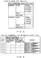
- FIG. 14 shows an example of the filtering information table.
- the priority levels assume values ranging from 0x00 to 0xFF expressed by 8 bits. As the value is smaller, the priority is higher. 0x00 indicates a packet to be "always transmitted", and 0xFF indicates a packet to be "always abandoned" (priority need not always be expressed by 8 bits).
- This value indicates the number of data bytes that can be transmitted per cycle (the interval between adjacent control packets indicating the coding cycles). Normally, the required bit rate (available network bandwidth) is given as the number of bits per second (bps: bits per second) of transmission data, and the value obtained by converting this value into Bpc (Bytes per cycle) is held in the table.
- Bpc can be changed in accordance with an external instruction during stream transmission. (If Bpc is changed to a smaller value, the discrimination boundary priority level (discrimination boundary level; to be described later) is initialized. If Bpc is changed to a larger value, the filtering discrimination processing continues.)
- cycle informing packets and a stream end packet are used.
- the correspondence between the identifiers and the attributes (cycle information, stream end) of control packets is assumed to be determined in advance.
- the contents of the packet type identifier field, link field, and packet length fields are copied.
- the data in the packet length field is used for counting the number of transmitted bytes. (When the data in the packet length field indicates the payload size, the header size is added thereto.)
- the value of the discrimination boundary level is incremented by one (to lower the discrimination boundary level).
- the packet sizes transmitted within one coding cycle are summed up. This value is reset for each cycle.
- a frame indicates the encoded data unit (data abandonment unit).
- the frame corresponds to data for one frame.
- the frame counter counts the number of frames that have the same priority as the discrimination boundary level present in one cycle. Data for one frame is divided into a plurality of packets in some cases. Accordingly, upon counting the number of frames, it is checked by looking up the link field in each packet header if the packet corresponds to a frame head packet. The frame counter is reset for each cycle.
- FIG. 15 shows the method of discriminating the frame boundary in a multiplexed stream using the link field.
- This value indicates the number of frames which are permitted to be transmitted during one cycle and have the same priority as the discrimination boundary level. After packets for one cycle have been transmitted, if the number of transmitted bytes in practice has not reached the number of transmittable bytes, this value is incremented by one (to gradually increase the number of frames to be transmitted during one cycle).
- the abandonment result flag includes a byte over flag and a frame over flag. Using these flags, whether or not the number of packets to be transmitted per cycle is to be increased is determined.
- This flag indicates that there is an abandonment result of packets having the same priority as the discrimination boundary level since the number of transmittable bytes would have been exceeded if they were not abandoned.
- This flag is reset for each cycle. When this flag is OFF, it means that there is no packet abandonment result; if the flag is ON, it means that there is a packet abandonment result.
- This flag indicates that there is an abandonment result of packets having the same priority as the discrimination boundary level since the number of transmission-permitted frames would have been exceeded if they were not abandoned. This flag is reset for each cycle.
- This flag indicates that the number of packets to be transmitted is not increased any more since the data volume transmitted per cycle has reached the number of transmittable bytes.
- FIG. 16 is a flow chart for explaining the out line of the processing of the stream shaping processing unit in the video transmission system of the present invention.
- the stream shaping processing will be described below with reference to the flow chart shown in FIG. 16.
- the stream shaping processing unit 12 performs initialization processing, generation of the filtering information table 28 by the table generation section 20, and the like prior to stream transmission (step A1). Thereafter, the stream shaping processing unit 12 starts the stream shaping processing simultaneously with the beginning of transmission of an encoded stream from the input unit 10.
- the header extraction section 24 detects the packet headers from the encoded stream (step A2).
- the header extraction section 24 extracts the packet header portions used in filtering discrimination and transfers them as header information to the filtering discrimination section 22. Also, the section 24 transfers packets to the packet holding section 26 to store them in the section 26 (step A3).
- the filtering discrimination section 22 executes filtering discrimination on the basis of information included in the header information, and informs the packet holding section 26 of the discrimination result (step A4). As a result of discrimination, if it is determined that the packet of interest is to be transmitted, the packet holding section 26 outputs the held packet of interest to the next transmission unit 14 (step A5). On the other hand, if it is determined that the packet of interest is to be abandoned, the packet holding section 26 drops the packet of interest.
- step A6 If the encoded stream input from the input unit 10 has not reached its stream end and packets still remain, the same processing is repeated for the subsequent packets. If the stream end has been reached, the processing ends (step A6).
- the stream shaping processing is executed by packet filtering.
- the packet filtering method includes the following two methods.
- FIG. 17 is a flow chart showing the simple filtering discrimination processing.
- simple filtering discrimination whether packets are to be transmitted or abandoned is simply determined using the packet identifier values alone.
- the priority level (0x00) indicating "always transmit” and the priority level (0xFF) indicating "always abandon” must be set in the correspondence table between the packet identifiers and packet priority levels.
- the filtering discrimination section 22 acquires the packet identifier from each header (step B1).
- the filtering discrimination section 22 If the acquired packet identifier indicates a control packet (i.e., a cycle informing packet or stream end packet), the filtering discrimination section 22 outputs a packet transmission message to the packet holding section 26, and ends the filtering discrimination processing (may inhibit the control packets from being transmitted to the receiving system).
- a control packet i.e., a cycle informing packet or stream end packet
- the filtering discrimination section 22 looks up the filtering information table 28 using the identifier as a key to acquire the packet priority level corresponding to the identifier (step B3).
- the filtering discrimination section 22 If the acquired packet priority level indicates "always transmit” (0x00), the filtering discrimination section 22 outputs a packet transmission message to the packet holding section 26 and ends the filtering discrimination processing (step B5).
- the filtering discrimination section 22 outputs a packet abandonment message to the packet holding section 26 and ends the filtering discrimination processing (step B6).
- FIG. 18 shows changes over time in packet transmission state of video data while taking MPEG as an example.
- the first cycle only packets including I picture data with highest priority are transmitted.
- packets including P picture data are gradually added to the packets to be transmitted.
- the number of packets to be transmitted ceases to increase.
- the following three different comparison discrimination processing operations are executed.
- FIG. 19 is a flow chart showing the filtering discrimination processing with bit rate control. This processing will be explained below with reference to the flow chart in FIG. 19.
- step D1 initialization processing (step D1) shown in the flow chart in FIG. 20 has already been executed prior to the beginning of transmission.
- the filtering discrimination section 22 acquires the packet identifier, link information, and packet length in the individual fields from each packet header obtained from the header extraction section 24 (step C1). The filtering discrimination section 22 looks up the most significant bit of the packet identifier to check if the packet of interest is a control packet (step C2).
- step C3 If the packet of interest is a control packet and a cycle packet (step C3), the filtering discrimination section 22 executes cycle start processing (step C4).
- cycle start processing the packet abandonment result in the previous cycle is checked to update the discrimination boundary level and the number of transmission-permitted frames, and to reset various cycle variables.
- the filtering discrimination section 22 When the control packet is to be transmitted to the receiving system, the filtering discrimination section 22 outputs a packet transmission message to the packet holding section 26 (step C5), updates the number of transmitted bytes (step C6), and then ends filtering discrimination (the control packet may not be transmitted).
- the filtering discrimination section 22 looks up the filtering information table 28 using the header identifier as a key to acquire the packet priority level corresponding to the identifier (step C7).
- the filtering discrimination section 22 executes frame count processing (step C8; its processing procedure will be described in detail later (FIG. 23)).
- step C8 the number of frames to which packets having the same priority as the discrimination boundary level belong is counted by looking up the identifiers and link fields in the packet headers. This is to accurately count the number of frames even when data belonging to one frame is divided into a plurality of packets.
- the filtering discrimination section 22 generates a discrimination code (step C9; this processing procedure will be described in detail later (FIG. 24)).
- the discrimination code summarizes the results of the three different comparison discrimination processing operations, and is used for determining packet transmission/abandonment.
- the filtering discrimination section 22 executes discrimination 1 (for determining whether the packet is to be transmitted/abandoned) on the basis of the discrimination code (step C10), and then executes processing in correspondence with the discrimination result.
- the filtering discrimination section 22 determines packet transmission, and outputs a packet transmission message to the packet holding section 26 (step C15). Also, the section 22 updates the number of transmitted bytes (step C16).
- step C10 determines packet abandonment, and outputs a packet abandonment message to the packet holding section 26 (step C11).
- the filtering discrimination section 22 executes discrimination 2 (step C12) to obtain the reason for packet abandonment, and then executes processing corresponding to the obtained reason.
- the filtering discrimination processing ends without any processing.
- the byte over flag is turned on (step C13).
- the frame over flag is turned on (step C14).
- FIG. 21 is a flow chart showing in detail the cycle head (start) processing (FIG. 19 (step C4)).
- the head of the cycle also means the end of the previous cycle.
- initialization processing for resetting various cycle variables at the head of the cycle is performed (step E9). More specifically, the initialization processing at the head of the cycle resets the frame counter, the number of transmitted bytes, the number of abandoned bytes, the frame over flag, and the byte over flag.
- FIG. 22 summarizes the transmission result confirmation processing of the previous cycle.
- step E1 if the fix flag is OFF (step E1), and if the byte over flag and the frame over flag are respectively OFF and ON (steps E2 and E5), since the number of transmittable bytes has not been reached yet, the filtering discrimination section 22 increments the number of frames to be transmitted per cycle by one. (step E6).
- step E1 determines that the boundary level of packet transmission/abandonment is determined, turns on the fix flag (step E3), and decrements the number of transmission-permitted frames by one to fall within the allowable range (step E4).
- the filtering discrimination section 22 sets the number of transmission-permitted frames for the next lower level at 1 (step E7), and increments the discrimination boundary level value by one, i.e., lowers the discrimination boundary level (step E8).
- FIG. 23 is a flow chart showing in detail the frame count processing (FIG. 19 (step C8)).
- the filtering discrimination section 22 compares the priority level and the discrimination boundary level (comparison 1) to check if the packet of interest has the same priority as the discrimination boundary level (step F1). As a result, if the packet of interest has the same priority as the discrimination boundary level, the filtering discrimination section 22 counts the number of frames of the packet. The frame boundary is confirmed based on the link field in the packet header (steps F2 and F3).
- FIG. 24 is a flow chart showing in detail the discrimination code generation processing (FIG. 19 (step C9)).
- the discrimination code (8 bits) summarizes the results of the three comparison arithmetic operations required for determining packet transmission/abandonment.
- step G5 The frame number of a frame to which the packet to be discriminated belongs
- step G6 The comparison arithmetic operation result is saved in the second lower bit of the discrimination code.
- step G7 The number of transmitted bytes if the packet to be discriminated is assumed to be transmitted" and "the number of transmittable bytes per cycle" are compared (step G7). If the number of transmittable bytes has been reached, this means that the number of packets to be transmitted per cycle can no longer be increased.
- the comparison arithmetic operation result is saved in the least significant bit of the discrimination code (step G8).
- FIG. 25 shows the code assignment of the comparison arithmetic operation results upon generation of the discrimination code
- FIG. 26 shows the correspondence between the discrimination code (assigned code) and the processing contents of the packet processing.
- FIG. 27 shows changes in bit rate as a result of the stream shaping processing of the video transmission system in this embodiment.
- the bold line indicates the stream after the shaping processing
- the thin line indicates the designated bit rate
- the dotted line indicates the original encoded stream
- the alternate long and short dashed line indicates the stream subjected to the full shaping processing.
- the transmitted data volume is lower than the target bit rate (designated bit rate).
- the number of packets to be transmitted is gradually increased in units of coding cycles in consideration of packet priority, and the bit rate is made to approach the target bit rate (see FIG. 18).
- bit rate is changed to a value larger than the target bit rate designated so far, the number of packets to be transmitted is increased again from that in the transmission state so far, thereby making the bit rate approach the new target bit rate.
- an input stream is packetized in units of hierarchical data in the hierarchically encoded stream to obtain an encoded stream in which priority levels are added to the individual packets, and the encoded stream is transmitted while executing bit rate control based on packet filtering in consideration of the available network bandwidth, packet priority, and user's demands.
- the bit rate control not only can set designated levels prepared in advance, but also can arbitrary set the bit rate of the stream to be transmitted, and can dynamically control the bit rate not to exceed the designated bit rate.
- the encoded stream to be transmitted is the one in which video data, audio data, user data, and the like are multiplexed, and the bit rate control method of the video data portion has been mainly described. If audio data is hierarchically encoded, the audio data portion can be subjected to the bit rate control. Of course, the bit rate control can be made for other types of data.
- dynamic bit rate control can be realized according to the designated bit rate independently of the moving image coding scheme used.
Abstract
Description
Claims (16)
- A data transmission system comprising:input means (00) for inputting an encoded stream which is packetized in units of abandonable data, and in which a header including a packet identifier is added to each of packets;transmission means (04) for transmitting the encoded stream input from said input means (00) onto an network;designation means (38) for designating a bit rate; andcontrol means (02) for controlling a bit rate upon transmission of the encoded stream by said transmission means (04) by abandoning a specific packet using packet priority determined on the basis of the packet identifier included in the header of each packet in accordance with the bit rate designated by said designation means (38).
- A system according to claim 1, wherein control packets indicating coding cycles are cyclically inserted in the encoded stream, and said control means (02) determines transmission or abandonment of the specific packet not to exceed the bit rate designated by said designation means (38) while increasing the number of packets to be transmitted in units of cycles discriminated based on the control packets.
- A data transmission system for transmitting an encoded stream via a network, comprising:stream coding means (34) for generating said encoded stream which is packetized in units of abandonable data, and in which a header including a packet identifier also serving as packet priority is added to each of packets;stream shaping processing means (12) for determining transmission or abandonment of each of the packets in the encoded stream generated by said stream coding means (34) using the packet identifier included in the header of each packet in accordance with a designated bit rate; andtransmission means (14) for transmitting the encoded stream made up of packets which are determined to be transmitted by said stream shaping processing means (12).
- A system according to claim 3, wherein said designation means (38) comprises means for dynamically changing the bit rate during transmission of the encoded stream by said transmission means.
- A system according to claim 3, wherein said stream shaping processing means (12) comprises:table generation means (20) for generating a filtering information table in which a correspondence between the packet identifier included in the header of each packet of the encoded stream generated by said stream coding means (34), and packet priority is registered; andfiltering discrimination means (22) for discriminating transmission or abandonment of each of the packets with reference to the filtering information table generated by said table generation means (20) on the basis of the packet identifier included in the header extracted from each packet in the encoded stream to be transmitted.
- A system according to claim 5, wherein said table generation means (20) comprises setting means for setting the correspondence between the packet identifier and packet priority by reflecting an externally input designation.
- A system according to claim 3, wherein said stream coding means (34) comprises generation means for generating the encoded stream by cyclically inserting control packets indicating coding cycles, and said stream shaping processing means (12) determines transmission or abandonment of each packet not to exceed the bit rate designated by designation means (38) while increasing the number of packets to be transmitted in units of cycles discriminated based on the control packets.
- A system according to claim 7, wherein said stream shaping processing means (12) comprises:holding means for holding discrimination boundary priority to be compared with the priority based on the packet identifier so as to determine transmission or abandonment of each packet;number of packets increasing means for gradually increasing the number of packets having the same priority as the discrimination boundary priority in units of cycles discriminated based on the control packets by transmitting packets having priority higher than the discrimination boundary priority and abandoning packets having priority lower than the discrimination boundary priority;priority changing means for lowering the discrimination boundary priority after all packets having the same priority as the discrimination boundary priority in one cycle are transmitted; andmeans for stopping increases in the number of packets to be transmitted when the designated bit rate is reached.
- A system according to claim 3, wherein said stream coding means (34) provides a hierarchical structure to the packet identifier included in the header, and generates the encoded stream which expresses packet priority based on contents of the individual layers of the hierarchical structure.
- A system according to claim 3, wherein said stream coding means (34) generates the encoded stream which allows to discriminate if the packet identifier included in the header has absolute packet priority or variable packet priority.
- A system according to claim 3, wherein said stream coding means (34) comprises means for generating an encoded stream in which the packet identifier included in the header can be set to indicate whether or not a packet is abandonable.
- A system according to claim 3, wherein said stream coding means (34) comprises means for setting data indicating a link relationship between previous and next packets in the header.
- A relay node which is arranged on a network route and is located between a data transmitting system and a data receiving system, comprising:reception means (74) for receiving an encoded stream from said transmitting system;stream shaping processing means (72) for determining transmission or abandonment of each of packets in said encoded stream which is packetized in units of abandonable data, in which a header including a packet identifier also serving as packet priority is added to each of the packets, and which is transmitted from the data transmitting system, using priority based on the packet identifier included in the header of each of the packets in accordance with a designated bit rate; andtransmission means (76) for transmitting the encoded stream made up of the packets which are determined to be transmitted by said stream shaping processing means to the data receiving system via the network.
- A data transmission method for transmitting an encoded stream via a network, comprising:the input step of inputting an encoded stream which is packetized in units of abandonable data, and in which a header including a packet identifier is added to each of packets;the transmission step of transmitting the encoded stream input in the input step onto the network;the designation step of designating a bit rate; andthe control step of controlling a bit rate upon transmission of the encoded stream in the transmission step by abandoning a specific packet using packet priority determined on the basis of the packet identifier included in the header of each packet in accordance with the bit rate designated in the designation step.
- A data transmission method for transmitting an encoded stream via a network, comprising:transmitting said encoded stream which is packetized in units of abandonable data and in which a header including a packet identifier is added to each of packets, while controlling a bit rate by transmitting or abandoning each of the packets using packet priority determined based on the packet identifier included in the header of each packet in units of packets in accordance with a designated bit rate.
- A method according to claim 15, wherein control packets indicating coding cycles are cyclically inserted in the encoded stream, and transmission or abandonment of the specific packet is determined not to exceed the designated bit rate while increasing the number of packets to be transmitted in units of cycles discriminated based on the control packets.
Applications Claiming Priority (3)
| Application Number | Priority Date | Filing Date | Title |
|---|---|---|---|
| JP1367/97 | 1997-01-08 | ||
| JP136797 | 1997-01-08 | ||
| JP136797A JP3193947B2 (en) | 1997-01-08 | 1997-01-08 | Data transmission system and data transmission method |
Publications (2)
| Publication Number | Publication Date |
|---|---|
| EP0853407A2 true EP0853407A2 (en) | 1998-07-15 |
| EP0853407A3 EP0853407A3 (en) | 2002-11-06 |
Family
ID=11499535
Family Applications (1)
| Application Number | Title | Priority Date | Filing Date |
|---|---|---|---|
| EP97111245A Withdrawn EP0853407A3 (en) | 1997-01-08 | 1997-07-04 | Data transmission system and method |
Country Status (3)
| Country | Link |
|---|---|
| US (1) | US6222841B1 (en) |
| EP (1) | EP0853407A3 (en) |
| JP (1) | JP3193947B2 (en) |
Cited By (35)
| Publication number | Priority date | Publication date | Assignee | Title |
|---|---|---|---|---|
| WO2000030278A1 (en) * | 1998-11-12 | 2000-05-25 | Sony Corporation | Data multiplexing device and data multiplexing method, and data transmitter |
| WO2001041399A2 (en) * | 1999-12-03 | 2001-06-07 | Digital Pipe, Inc. | Method for providing streaming media data in a network-based environment |
| FR2803472A1 (en) * | 2000-01-03 | 2001-07-06 | Nptv | COMPUTER METHOD FOR OPERATING AN INTERACTIVE DIGITAL TELEVISION TRANSMISSION |
| WO2002003584A2 (en) * | 2000-06-30 | 2002-01-10 | Nokia Corporation | Head end device for use in a hierarchical broadband broadcast network, and method and system for transmitting content data in a hierarchical network |
| WO2002007388A2 (en) * | 2000-07-14 | 2002-01-24 | At & T Corp. | Frame classification for qos-driven wireless local area networks |
| WO2002030046A2 (en) * | 2000-10-04 | 2002-04-11 | Vitesse Semiconductor Corporation | A method and system for analysing a data packet or frame |
| WO2002032147A1 (en) * | 2000-10-11 | 2002-04-18 | Koninklijke Philips Electronics N.V. | Scalable coding of multi-media objects |
| WO2003098930A1 (en) | 2002-05-21 | 2003-11-27 | Sony Corporation | Information processing device and method, recording medium, and program |
| US6744738B1 (en) | 1999-06-12 | 2004-06-01 | Samsung Electronics Co., Ltd. | Wireless communication system for video packet transmission |
| US6804222B1 (en) | 2000-07-14 | 2004-10-12 | At&T Corp. | In-band Qos signaling reference model for QoS-driven wireless LANs |
| EP1028593A3 (en) * | 1999-02-11 | 2005-01-26 | PacketVideo Corporation | Method and device for control and delivery of digitally compressed visual data in a heterogeneous communication network |
| US6850981B1 (en) | 2000-07-14 | 2005-02-01 | At&T Corp. | System and method of frame scheduling for QoS-driven wireless local area network (WLAN) |
| US6862270B1 (en) | 2000-07-14 | 2005-03-01 | At&T Corp. | Architectural reference model for QoS-driven wireless LANs |
| WO2005022867A1 (en) * | 2003-08-27 | 2005-03-10 | Siemens Aktiengesellschaft | Method for transmitting data in a data network |
| US6950397B1 (en) | 2000-07-14 | 2005-09-27 | At&T Corp. | RSVP/SBM based side-stream session setup, modification, and teardown for QoS-driven wireless lans |
| US6970422B1 (en) | 2000-07-14 | 2005-11-29 | At&T Corp. | Admission control for QoS-Driven Wireless LANs |
| US6999442B1 (en) | 2000-07-14 | 2006-02-14 | At&T Corp. | RSVP/SBM based down-stream session setup, modification, and teardown for QOS-driven wireless lans |
| US7031287B1 (en) | 2000-07-14 | 2006-04-18 | At&T Corp. | Centralized contention and reservation request for QoS-driven wireless LANs |
| US7039032B1 (en) | 2000-07-14 | 2006-05-02 | At&T Corp. | Multipoll for QoS-Driven wireless LANs |
| US7068633B1 (en) | 2000-07-14 | 2006-06-27 | At&T Corp. | Enhanced channel access mechanisms for QoS-driven wireless lans |
| US7068632B1 (en) | 2000-07-14 | 2006-06-27 | At&T Corp. | RSVP/SBM based up-stream session setup, modification, and teardown for QOS-driven wireless LANs |
| US7142563B1 (en) | 2001-02-20 | 2006-11-28 | At&T Corp. | Service interface for QoS-driven HPNA networks |
| US7151762B1 (en) | 2000-07-14 | 2006-12-19 | At&T Corp. | Virtual streams for QoS-driven wireless LANs |
| FR2899758A1 (en) * | 2006-04-07 | 2007-10-12 | France Telecom | METHOD AND DEVICE FOR ENCODING DATA INTO A SCALABLE FLOW |
| US7403538B1 (en) | 1998-10-07 | 2008-07-22 | At&T Corporation | Voice data integrated multiaccess by self-reservation and contention algorithm |
| DE10344017B4 (en) * | 2002-09-17 | 2009-02-26 | Samsung Electronics Co., Ltd., Suwon | Server, client, apparatus and method for streaming multimedia data and network bandwidth measurement techniques |
| CN101621546A (en) * | 2008-07-01 | 2010-01-06 | 索尼株式会社 | Packet tagging for effective multicast content distribution |
| WO2010002420A1 (en) * | 2008-07-01 | 2010-01-07 | Thomson Licensing | Network abstraction layer (nal)-aware multiplexer |
| US7656798B1 (en) | 2001-02-20 | 2010-02-02 | At&T Intellectual Property Ii, L.P. | Service interface for QoS-driven HPNA networks |
| US7756092B1 (en) | 2000-07-14 | 2010-07-13 | At&T Intellectual Property Ii, L.P. | In-band QoS signaling reference model for QoS-driven wireless LANs connected to one or more networks |
| US7860053B1 (en) | 1998-10-07 | 2010-12-28 | At&T Intellectual Property Ii, L.P. | Voice-data integrated multiaccess by self-reservation and stabilized aloha contention |
| WO2011093835A1 (en) * | 2010-01-28 | 2011-08-04 | Thomson Licensing | A method and apparatus for parsing a network abstraction-layer for reliable data communication |
| CN104219160A (en) * | 2013-05-31 | 2014-12-17 | 华为技术有限公司 | Method and device for generating input parameter |
| US9306708B2 (en) | 2009-10-07 | 2016-04-05 | Thomson Licensing | Method and apparatus for retransmission decision making |
| CN108781139A (en) * | 2016-02-26 | 2018-11-09 | 网络洞察力知识产权公司 | Data in packet network retransmit |
Families Citing this family (107)
| Publication number | Priority date | Publication date | Assignee | Title |
|---|---|---|---|---|
| CN100393007C (en) * | 1997-06-13 | 2008-06-04 | 皇家菲利浦电子有限公司 | Cyclic transmission of plurality of mutually related objects |
| JP3516432B2 (en) * | 1997-11-18 | 2004-04-05 | 株式会社東芝 | Node device and packet transfer method |
| US7630570B1 (en) | 1998-05-06 | 2009-12-08 | At&T Intellectual Property Ii, L.P. | Method and apparatus to prioritize video information during coding and decoding |
| JP2955561B1 (en) | 1998-05-29 | 1999-10-04 | 株式会社ディジタル・ビジョン・ラボラトリーズ | Stream communication system and stream transfer control method |
| US6584509B2 (en) * | 1998-06-23 | 2003-06-24 | Intel Corporation | Recognizing audio and video streams over PPP links in the absence of an announcement protocol |
| US6560229B1 (en) * | 1998-07-08 | 2003-05-06 | Broadcom Corporation | Network switching architecture with multiple table synchronization, and forwarding of both IP and IPX packets |
| JP3234573B2 (en) * | 1998-08-31 | 2001-12-04 | 松下電器産業株式会社 | Packet filtering device |
| US6868061B1 (en) * | 1998-12-10 | 2005-03-15 | Nokia Corporation | System and method for pre-filtering low priority packets at network nodes in a network service class utilizing a priority-based quality of service |
| US6611872B1 (en) | 1999-01-11 | 2003-08-26 | Fastforward Networks, Inc. | Performing multicast communication in computer networks by using overlay routing |
| CN1153427C (en) | 1999-01-26 | 2004-06-09 | 松下电器产业株式会社 | Method and device for data trunking processing and information discarding and program recording medium |
| EP1172723A1 (en) * | 1999-03-30 | 2002-01-16 | Matsushita Electric Industrial Co., Ltd. | Data processing system, data transmitting/receiving device, and recorded medium |
| US6735633B1 (en) * | 1999-06-01 | 2004-05-11 | Fast Forward Networks | System for bandwidth allocation in a computer network |
| JP3788125B2 (en) * | 1999-08-25 | 2006-06-21 | 株式会社日立製作所 | Packet transmission / reception method and apparatus |
| JP2001111619A (en) * | 1999-10-12 | 2001-04-20 | Sony Corp | Transmitter, communication system and its communication method |
| EP1250776A1 (en) * | 1999-10-29 | 2002-10-23 | Forskarpatent i Västsverige AB | Method and arrangements for congestion control in packet networks using thresholds and demoting of packet flows |
| US6975655B2 (en) * | 2000-04-07 | 2005-12-13 | Broadcom Corporation | Method of controlling data sampling clocking of asynchronous network nodes in a frame-based communications network |
| US7647619B2 (en) * | 2000-04-26 | 2010-01-12 | Sony Corporation | Scalable filtering table |
| US6985442B1 (en) * | 2000-07-26 | 2006-01-10 | Lucent Technologies Inc. | Technique for bandwidth sharing in internet and other router networks without per flow state record keeping |
| JP3590949B2 (en) * | 2000-08-17 | 2004-11-17 | 松下電器産業株式会社 | Data transmission device and data transmission method |
| WO2002021822A2 (en) * | 2000-09-02 | 2002-03-14 | Emageon, Inc. | Methods and apparatus for streaming dicom images through data element sources and sinks |
| DE60036493T2 (en) * | 2000-10-03 | 2008-08-21 | U4Ea Technologies Ltd. | DATA FLOW CONTROL |
| ATE498261T1 (en) * | 2000-10-03 | 2011-02-15 | Gos Networks Ltd | PACKET SEQUENCE CONTROL |
| AUPR063400A0 (en) * | 2000-10-06 | 2000-11-02 | Canon Kabushiki Kaisha | Xml encoding scheme |
| US7971227B1 (en) * | 2000-10-25 | 2011-06-28 | Xm Satellite Radio Inc. | Method and apparatus for implementing file transfers to receivers in a digital broadcast system |
| JP2002141945A (en) * | 2000-11-06 | 2002-05-17 | Sony Corp | Data transmission system and data transmission method, and program storage medium |
| US6819878B1 (en) * | 2000-11-08 | 2004-11-16 | Nortel Networks Limited | Packet-based optical communications networks |
| KR100550727B1 (en) * | 2000-12-28 | 2006-02-08 | 엘지전자 주식회사 | Method for rate Indication and rate decision of High-speed Data Channel in Mobile Communication System |
| US20020097678A1 (en) * | 2001-01-23 | 2002-07-25 | Bisher James A. | Method and apparatus for bandwidth management associated with misbehaving sessions |
| US20020180891A1 (en) * | 2001-04-11 | 2002-12-05 | Cyber Operations, Llc | System and method for preconditioning analog video signals |
| JP2002344937A (en) * | 2001-05-16 | 2002-11-29 | Fujitsu Ltd | Quality control assurance method and quality control assurance device, and network connection device |
| ES2247412T3 (en) * | 2001-08-24 | 2006-03-01 | Siemens Aktiengesellschaft | PROCEDURE FOR THE TRANSMISSION OF DATA PACKAGES IN A RADIO COMMUNICATION SYSTEM AND A CORRESPONDING RADIO STATION. |
| CN1265650C (en) * | 2001-08-31 | 2006-07-19 | 皇家飞利浦电子股份有限公司 | Method and device for sending a user data inserted in a coded video signal |
| KR100431003B1 (en) * | 2001-10-31 | 2004-05-12 | 삼성전자주식회사 | Data transmitting/receiving system and method thereof |
| JP2003152544A (en) * | 2001-11-12 | 2003-05-23 | Sony Corp | Data communication system, data transmitter, data receiver, data-receiving method and computer program |
| DE10197195D2 (en) * | 2001-12-10 | 2004-10-28 | Siemens Ag | Process for the transfer of data from applications with different quality |
| JP4162454B2 (en) * | 2002-09-10 | 2008-10-08 | 三洋電機株式会社 | Data processing device |
| US7660352B2 (en) * | 2003-04-04 | 2010-02-09 | Sony Corporation | Apparatus and method of parallel processing an MPEG-4 data stream |
| US7526202B2 (en) * | 2003-05-19 | 2009-04-28 | Intel Corporation | Architecture and method for framing optical control and data bursts within optical transport unit structures in photonic burst-switched networks |
| JP4237549B2 (en) * | 2003-05-29 | 2009-03-11 | 株式会社日立国際電気 | Circulation recorder |
| US7729992B2 (en) * | 2003-06-13 | 2010-06-01 | Brilliant Digital Entertainment, Inc. | Monitoring of computer-related resources and associated methods and systems for disbursing compensation |
| US8095500B2 (en) | 2003-06-13 | 2012-01-10 | Brilliant Digital Entertainment, Inc. | Methods and systems for searching content in distributed computing networks |
| JP4335619B2 (en) | 2003-09-04 | 2009-09-30 | 株式会社エヌ・ティ・ティ・ドコモ | Packet priority control apparatus and method |
| US20050068968A1 (en) * | 2003-09-30 | 2005-03-31 | Shlomo Ovadia | Optical-switched (OS) network to OS network routing using extended border gateway protocol |
| US7778245B2 (en) * | 2003-11-10 | 2010-08-17 | Broadcom Corporation | Method and apparatus for remapping module identifiers and substituting ports in network devices |
| US7450147B2 (en) * | 2003-12-22 | 2008-11-11 | At&T Intellectual Property | Network-enabled peer-to-peer video calling systems, methods, and storage medium |
| KR100664278B1 (en) * | 2004-01-09 | 2007-01-04 | 엘지전자 주식회사 | Radio communication system providing mbms |
| US8018850B2 (en) | 2004-02-23 | 2011-09-13 | Sharp Laboratories Of America, Inc. | Wireless video transmission system |
| US8023408B2 (en) * | 2004-11-19 | 2011-09-20 | International Business Machines Corporation | Dynamically changing message priority or message sequence number |
| US20060168012A1 (en) * | 2004-11-24 | 2006-07-27 | Anthony Rose | Method and system for electronic messaging via distributed computing networks |
| US7738385B2 (en) * | 2004-11-30 | 2010-06-15 | Broadcom Corporation | Mirroring of data in a network device |
| EP2002653A2 (en) * | 2004-12-08 | 2008-12-17 | Imagine Communications Ltd., | Distributed statistical multiplexing of multi-media |
| JP4559237B2 (en) * | 2005-01-07 | 2010-10-06 | 株式会社エヌ・ティ・ティ・ドコモ | Routing method and mobile terminal |
| EP1847071A4 (en) | 2005-01-26 | 2010-10-20 | Internet Broadcasting Corp B V | Layered multicast and fair bandwidth allocation and packet prioritization |
| US20060187917A1 (en) * | 2005-02-18 | 2006-08-24 | Broadcom Corporation | Pre-learning of values with later activation in a network device |
| US7529191B2 (en) * | 2005-02-18 | 2009-05-05 | Broadcom Corporation | Programmable metering behavior based on table lookup |
| US7606231B2 (en) | 2005-02-18 | 2009-10-20 | Broadcom Corporation | Pipeline architecture for a network device |
| US8331380B2 (en) * | 2005-02-18 | 2012-12-11 | Broadcom Corporation | Bookkeeping memory use in a search engine of a network device |
| US7577096B2 (en) * | 2005-02-18 | 2009-08-18 | Broadcom Corporation | Timestamp metering and rollover protection in a network device |
| US8457131B2 (en) * | 2005-02-18 | 2013-06-04 | Broadcom Corporation | Dynamic table sharing of memory space within a network device |
| US20060233247A1 (en) * | 2005-04-13 | 2006-10-19 | Visharam Mohammed Z | Storing SVC streams in the AVC file format |
| KR100657314B1 (en) * | 2005-05-04 | 2006-12-20 | 삼성전자주식회사 | Apparatus and method for transmitting multimedia streaming |
| JP2007066109A (en) * | 2005-08-31 | 2007-03-15 | Fujitsu Ltd | Apparatus and method for controlling data transmission/reception |
| US20070091926A1 (en) * | 2005-10-21 | 2007-04-26 | Apostolopoulos John G | Method for optimizing portions of data from a plurality of data streams at a transcoding node |
| US20070180349A1 (en) * | 2006-01-31 | 2007-08-02 | Jacobsen Eric A | Techniques for uequal error protection for layered protection applications |
| JP4636267B2 (en) * | 2006-02-28 | 2011-02-23 | 日本電気株式会社 | Encoding device and encoding bit rate switching method |
| US8514871B2 (en) * | 2006-07-24 | 2013-08-20 | At&T Intellectual Property I, L.P. | Methods, systems, and computer program products for marking data packets based on content thereof |
| US8856267B2 (en) * | 2006-11-16 | 2014-10-07 | Rangecast Technologies, Llc | Network audio directory server and method |
| US8281338B2 (en) * | 2007-02-27 | 2012-10-02 | Microsoft Corporation | Extensible encoding for interactive user experience elements |
| US9019830B2 (en) * | 2007-05-15 | 2015-04-28 | Imagine Communications Corp. | Content-based routing of information content |
| JP4790663B2 (en) * | 2007-05-16 | 2011-10-12 | 富士通株式会社 | Relay device |
| EP2153566A1 (en) | 2007-05-16 | 2010-02-17 | Thomson Licensing | Apparatus and method for encoding and decoding signals |
| JP4958284B2 (en) * | 2007-05-23 | 2012-06-20 | Kddi株式会社 | Radio station and program for relay control of packets in ad hoc network |
| JP5232865B2 (en) | 2007-10-15 | 2013-07-10 | トムソン ライセンシング | Preamble of digital television system |
| CA2701688A1 (en) | 2007-10-15 | 2009-04-23 | Thomson Licensing | Apparatus and method for encoding and decoding signals |
| CA2620337C (en) | 2008-02-04 | 2012-11-27 | Omnivex Corporation | Digital signage network |
| CA2616324C (en) * | 2008-02-04 | 2015-06-16 | Omnivex Corporation | Digital signage display |
| CA2822771C (en) * | 2008-02-04 | 2015-09-29 | Omnivex Corporation | Subscription based content delivery for a digital signage network |
| JP2009239514A (en) * | 2008-03-26 | 2009-10-15 | Nec Personal Products Co Ltd | Motion picture distribution apparatus, going-through device, and motion picture distribution system and method |
| WO2009138656A2 (en) * | 2008-04-29 | 2009-11-19 | France Telecom | Transmission of a video stream coded by hierarchical coding |
| JP2010034646A (en) * | 2008-07-25 | 2010-02-12 | Nec Corp | Relay device, relay method, and program |
| EP2150060A1 (en) * | 2008-07-28 | 2010-02-03 | Alcatel, Lucent | Method and arrangement for video encoding |
| US8645400B1 (en) * | 2008-08-01 | 2014-02-04 | Marvell International Ltd. | Flexible bit field search method |
| US9262357B2 (en) | 2008-09-29 | 2016-02-16 | International Business Machines Corporation | Associating process priority with I/O queuing |
| US8689343B2 (en) * | 2008-10-24 | 2014-04-01 | Manufacturing Resources International, Inc. | System and method for securely transmitting video data |
| US20100104003A1 (en) * | 2008-10-24 | 2010-04-29 | Manufacturing Resources International Inc. | System and method for securely transmitting video data |
| US9812047B2 (en) | 2010-02-25 | 2017-11-07 | Manufacturing Resources International, Inc. | System and method for remotely monitoring the operating life of electronic displays |
| JP2009273135A (en) * | 2009-05-22 | 2009-11-19 | Ntt Docomo Inc | Apparatus for packet-priority control and its method |
| US8627396B2 (en) * | 2009-06-12 | 2014-01-07 | Cygnus Broadband, Inc. | Systems and methods for prioritization of data for intelligent discard in a communication network |
| WO2010144833A2 (en) | 2009-06-12 | 2010-12-16 | Cygnus Broadband | Systems and methods for intelligent discard in a communication network |
| US8745677B2 (en) | 2009-06-12 | 2014-06-03 | Cygnus Broadband, Inc. | Systems and methods for prioritization of data for intelligent discard in a communication network |
| US8531961B2 (en) | 2009-06-12 | 2013-09-10 | Cygnus Broadband, Inc. | Systems and methods for prioritization of data for intelligent discard in a communication network |
| CN102714868A (en) * | 2010-01-06 | 2012-10-03 | 三菱电机株式会社 | Wireless communication apparatus and wireless communication method |
| US8723913B2 (en) * | 2010-10-07 | 2014-05-13 | T-Mobile Usa, Inc. | Rate adaptation for video calling |
| US8582579B2 (en) * | 2010-11-03 | 2013-11-12 | Broadcom Corporation | Priority packet processing |
| CN102427526A (en) * | 2011-09-23 | 2012-04-25 | 清华大学 | Low-delayed wireless video broadcast transmitting and coding method |
| CN102357347B (en) * | 2011-10-27 | 2013-10-09 | 天津工业大学 | Preparation method of modified polyacrylonitrile film |
| US10511649B2 (en) * | 2012-11-20 | 2019-12-17 | Pelco, Inc. | Method and apparatus for efficiently prioritizing elements in a video stream for low-bandwidth transmission |
| US9020469B2 (en) | 2013-06-04 | 2015-04-28 | Rangecast Technologies, Llc | Network audio distribution system and method |
| JP5941939B2 (en) * | 2014-03-14 | 2016-06-29 | ソフトバンク株式会社 | Video distribution device, video encoding device, and program |
| US10063476B2 (en) * | 2014-03-28 | 2018-08-28 | Research & Business Foundation Sungkyunkwan University | Content centric networking system providing differentiated service and method of controlling data traffic in content centric networking providing differentiated service |
| BR112016024301A2 (en) * | 2014-04-25 | 2022-07-19 | Sony Corp | transmission and reception apparatus and methods |
| CA2997779A1 (en) | 2015-09-10 | 2017-03-16 | Manufacturing Resources International, Inc. | System and method for systemic detection of display errors |
| US10908863B2 (en) | 2018-07-12 | 2021-02-02 | Manufacturing Resources International, Inc. | System and method for providing access to co-located operations data for an electronic display |
| US11137847B2 (en) | 2019-02-25 | 2021-10-05 | Manufacturing Resources International, Inc. | Monitoring the status of a touchscreen |
| US11402940B2 (en) | 2019-02-25 | 2022-08-02 | Manufacturing Resources International, Inc. | Monitoring the status of a touchscreen |
| US11115155B2 (en) * | 2019-09-09 | 2021-09-07 | Facebook Technologies, Llc | Systems and methods for prioritizing packet retransmission |
| US11921010B2 (en) | 2021-07-28 | 2024-03-05 | Manufacturing Resources International, Inc. | Display assemblies with differential pressure sensors |
Citations (1)
| Publication number | Priority date | Publication date | Assignee | Title |
|---|---|---|---|---|
| WO1996000487A1 (en) * | 1994-06-27 | 1996-01-04 | Loral Fairchild Corp. | System and method for providing multiple loss and service priorities |
Family Cites Families (11)
| Publication number | Priority date | Publication date | Assignee | Title |
|---|---|---|---|---|
| JPH03201641A (en) * | 1989-12-27 | 1991-09-03 | Toshiba Corp | Priority control system for communication packet |
| JPH04127747A (en) | 1990-09-19 | 1992-04-28 | Toshiba Corp | Variable rate encoding system |
| US5168356A (en) | 1991-02-27 | 1992-12-01 | General Electric Company | Apparatus for segmenting encoded video signal for transmission |
| US5253058A (en) | 1992-04-01 | 1993-10-12 | Bell Communications Research, Inc. | Efficient coding scheme for multilevel video transmission |
| US5270813A (en) | 1992-07-02 | 1993-12-14 | At&T Bell Laboratories | Spatially scalable video coding facilitating the derivation of variable-resolution images |
| DE4240226C2 (en) | 1992-11-30 | 1996-12-12 | Deutsche Forsch Luft Raumfahrt | Process for the digital transmission of hierarchical HDTV, EDTV and SDTV television signals |
| US5414455A (en) | 1993-07-07 | 1995-05-09 | Digital Equipment Corporation | Segmented video on demand system |
| US5481297A (en) | 1994-02-25 | 1996-01-02 | At&T Corp. | Multipoint digital video communication system |
| US5434848A (en) | 1994-07-28 | 1995-07-18 | International Business Machines Corporation | Traffic management in packet communications networks |
| ZA959722B (en) * | 1994-12-19 | 1996-05-31 | Alcatel Nv | Traffic management and congestion control for packet-based networks |
| JPH08191451A (en) | 1995-01-10 | 1996-07-23 | Canon Inc | Moving picture transmitter |
-
1997
- 1997-01-08 JP JP136797A patent/JP3193947B2/en not_active Expired - Lifetime
- 1997-05-14 US US08/856,493 patent/US6222841B1/en not_active Expired - Lifetime
- 1997-07-04 EP EP97111245A patent/EP0853407A3/en not_active Withdrawn
Patent Citations (1)
| Publication number | Priority date | Publication date | Assignee | Title |
|---|---|---|---|---|
| WO1996000487A1 (en) * | 1994-06-27 | 1996-01-04 | Loral Fairchild Corp. | System and method for providing multiple loss and service priorities |
Non-Patent Citations (2)
| Title |
|---|
| PASQUALE J C ET AL: "FILTER PROPAGATION IN DISSEMINATION TREES: TRADING OFF BANDWIDTH AND PROCESSING IN CONTINUOUS MEDIA NETWORKS" NETWORK AND OPERATING SYSTEM SUPPORT FOR DIGITAL AUDIO AND VIDEO. LANCASTER, NOV. 3 - 5, 1993, PROCEEDINGS OF THE INTERNATIONAL WORKSHOP ON NETWORK AND OPERATING SYSTEM SUPPORT FOR DIGITAL AUDIO AND VIDEO (NOSSDAV), BERLIN, SPRINGER, DE, vol. WORKSHOP 4, 3 November 1993 (1993-11-03), pages 259-268, XP000725324 ISBN: 3-540-58404-8 * |
| WITTIG H ET AL: "NETWORK LAYER SCALING: CONGESTION CONTROL IN MULTIMEDIA COMMUNICATION WITH HETEROGENOUS NETWORKS AND RECEIVERS" MULTIMEDIA TRANSPORT AND TELESERVICES. INTERNATIONAL COST 237 WORKSHOPPROCEEDINGS. VIENNA, NOV. 13 - 15, 1994, INTERNATIONAL COST 237 WORKSHOP PROCEEDINGS, BERLIN, SPRINGER, DE, 13 November 1994 (1994-11-13), pages 274-293, XP000585306 ISBN: 3-540-58759-4 * |
Cited By (71)
| Publication number | Priority date | Publication date | Assignee | Title |
|---|---|---|---|---|
| US7860053B1 (en) | 1998-10-07 | 2010-12-28 | At&T Intellectual Property Ii, L.P. | Voice-data integrated multiaccess by self-reservation and stabilized aloha contention |
| US8576827B2 (en) | 1998-10-07 | 2013-11-05 | At&T Intellectual Property Ii, L.P. | Voice data integrated multiaccess by self-reservation and contention algorithm |
| US7403538B1 (en) | 1998-10-07 | 2008-07-22 | At&T Corporation | Voice data integrated multiaccess by self-reservation and contention algorithm |
| US8320355B1 (en) | 1998-10-07 | 2012-11-27 | At&T Intellectual Property Ii, L.P. | Voice data integrated multiaccess by self-reservation and contention algorithm |
| US9351318B2 (en) | 1998-10-07 | 2016-05-24 | At&T Intellectual Property Ii, L.P. | Voice-data integrated multiaccess by self-reservation and stabilized aloha contention |
| US7664068B1 (en) | 1998-10-07 | 2010-02-16 | At&T Corp. | Voice data integrated multiaccess by self-reservation and contention algorithm |
| US8811165B2 (en) | 1998-10-07 | 2014-08-19 | At&T Intellectual Property Ii, L.P. | Voice-data integrated multiaccess by self-reservation and stabilized aloha contention |
| WO2000030278A1 (en) * | 1998-11-12 | 2000-05-25 | Sony Corporation | Data multiplexing device and data multiplexing method, and data transmitter |
| US7130265B1 (en) * | 1998-11-12 | 2006-10-31 | Sony Corporation | Data multiplexing device and data multiplexing method, and data transmitter |
| EP1028593A3 (en) * | 1999-02-11 | 2005-01-26 | PacketVideo Corporation | Method and device for control and delivery of digitally compressed visual data in a heterogeneous communication network |
| US6744738B1 (en) | 1999-06-12 | 2004-06-01 | Samsung Electronics Co., Ltd. | Wireless communication system for video packet transmission |
| WO2001041399A3 (en) * | 1999-12-03 | 2002-01-17 | Digital Pipe Inc | Method for providing streaming media data in a network-based environment |
| WO2001041399A2 (en) * | 1999-12-03 | 2001-06-07 | Digital Pipe, Inc. | Method for providing streaming media data in a network-based environment |
| FR2803472A1 (en) * | 2000-01-03 | 2001-07-06 | Nptv | COMPUTER METHOD FOR OPERATING AN INTERACTIVE DIGITAL TELEVISION TRANSMISSION |
| WO2001050764A1 (en) * | 2000-01-03 | 2001-07-12 | Canal + Technologies | Computerised method for operating an interactive digital television broadcast |
| WO2002003584A2 (en) * | 2000-06-30 | 2002-01-10 | Nokia Corporation | Head end device for use in a hierarchical broadband broadcast network, and method and system for transmitting content data in a hierarchical network |
| WO2002003584A3 (en) * | 2000-06-30 | 2002-12-12 | Nokia Corp | Head end device for use in a hierarchical broadband broadcast network, and method and system for transmitting content data in a hierarchical network |
| US8014372B2 (en) | 2000-07-14 | 2011-09-06 | At&T Intellectual Property Ii, L.P. | Multipoll for QoS-driven wireless LANs |
| US7756092B1 (en) | 2000-07-14 | 2010-07-13 | At&T Intellectual Property Ii, L.P. | In-band QoS signaling reference model for QoS-driven wireless LANs connected to one or more networks |
| US6950397B1 (en) | 2000-07-14 | 2005-09-27 | At&T Corp. | RSVP/SBM based side-stream session setup, modification, and teardown for QoS-driven wireless lans |
| US6970422B1 (en) | 2000-07-14 | 2005-11-29 | At&T Corp. | Admission control for QoS-Driven Wireless LANs |
| US6999442B1 (en) | 2000-07-14 | 2006-02-14 | At&T Corp. | RSVP/SBM based down-stream session setup, modification, and teardown for QOS-driven wireless lans |
| US7031287B1 (en) | 2000-07-14 | 2006-04-18 | At&T Corp. | Centralized contention and reservation request for QoS-driven wireless LANs |
| US7039032B1 (en) | 2000-07-14 | 2006-05-02 | At&T Corp. | Multipoll for QoS-Driven wireless LANs |
| US7068633B1 (en) | 2000-07-14 | 2006-06-27 | At&T Corp. | Enhanced channel access mechanisms for QoS-driven wireless lans |
| US7068632B1 (en) | 2000-07-14 | 2006-06-27 | At&T Corp. | RSVP/SBM based up-stream session setup, modification, and teardown for QOS-driven wireless LANs |
| US6862270B1 (en) | 2000-07-14 | 2005-03-01 | At&T Corp. | Architectural reference model for QoS-driven wireless LANs |
| US9686720B2 (en) | 2000-07-14 | 2017-06-20 | At&T Intellectual Property Ii, L.P. | Admission control for QoS-driven wireless LANs |
| US7151762B1 (en) | 2000-07-14 | 2006-12-19 | At&T Corp. | Virtual streams for QoS-driven wireless LANs |
| WO2002007388A2 (en) * | 2000-07-14 | 2002-01-24 | At & T Corp. | Frame classification for qos-driven wireless local area networks |
| US7298724B2 (en) | 2000-07-14 | 2007-11-20 | At&T Corp. | In-band QoS signaling reference model for QoS-driven wireless LANs |
| US9204338B2 (en) | 2000-07-14 | 2015-12-01 | At&T Intellectual Property Ii, L.P. | RSVP/SBM based up-stream session setup, modification, and teardown for QoS-driven wireless LANs |
| US6850981B1 (en) | 2000-07-14 | 2005-02-01 | At&T Corp. | System and method of frame scheduling for QoS-driven wireless local area network (WLAN) |
| US7450504B1 (en) | 2000-07-14 | 2008-11-11 | At&T Intellectual Property Ii, L.P. | Admission control for QoS-driven wireless LANs |
| US8989165B2 (en) | 2000-07-14 | 2015-03-24 | At&T Intellectual Property Ii, L.P. | Admission control for QoS-driven wireless LANs |
| US8855060B2 (en) | 2000-07-14 | 2014-10-07 | At&T Intellectual Property Ii, L.P. | Centralized contention and reservation request for QoS-driven wireless LANs |
| US8605707B2 (en) | 2000-07-14 | 2013-12-10 | At&T Intellectual Property Ii, L.P. | Enhanced channel access mechanisms for QoS-driven wireless LANs |
| US8503414B2 (en) | 2000-07-14 | 2013-08-06 | At&T Intellectual Property Ii, L.P. | RSVP/SBM based up-stream session setup, modification, and teardown for QoS-driven wireless LANs |
| US7646756B1 (en) | 2000-07-14 | 2010-01-12 | At&T Corp. | Multipoll for QoS-driven wireless LANs |
| US8437323B2 (en) | 2000-07-14 | 2013-05-07 | At&T Intellectual Property Ii, L.P. | Admission control for QoS-driven wireless LANs |
| US7664072B1 (en) | 2000-07-14 | 2010-02-16 | At&T Corp. | Virtual streams for QoS-driven wireless LANs |
| US6804222B1 (en) | 2000-07-14 | 2004-10-12 | At&T Corp. | In-band Qos signaling reference model for QoS-driven wireless LANs |
| US7738378B1 (en) | 2000-07-14 | 2010-06-15 | At&T Intellectual Property Ii, L.P. | RSVP/SBM based side-stream session setup, modification, and teardown for QoS-driven wireless LANs |
| US7756095B2 (en) | 2000-07-14 | 2010-07-13 | At&T Intellectual Property Ii, L.P. | In-band QoS signaling reference model for QoS-driven wireless LANs |
| US8130732B1 (en) | 2000-07-14 | 2012-03-06 | At&T Intellectual Property Ii, L.P. | Enhanced channel access mechanisms for QoS-driven wireless LANs |
| WO2002007388A3 (en) * | 2000-07-14 | 2003-02-06 | At & T Corp | Frame classification for qos-driven wireless local area networks |
| US8009649B1 (en) | 2000-07-14 | 2011-08-30 | At&T Intellectual Property Ii, L.P. | Admission control for QoS-driven wireless LANs |
| US7899012B2 (en) | 2000-07-14 | 2011-03-01 | At&T Intellectual Property Ii, L.P. | Virtual streams for QOS-driven wireless LANS |
| WO2002030046A3 (en) * | 2000-10-04 | 2002-08-01 | Vitesse Semiconductor Corp | A method and system for analysing a data packet or frame |
| WO2002030046A2 (en) * | 2000-10-04 | 2002-04-11 | Vitesse Semiconductor Corporation | A method and system for analysing a data packet or frame |
| US8374344B2 (en) | 2000-10-11 | 2013-02-12 | Koninklijke Philips Electronics N.V. | Coding |
| WO2002032147A1 (en) * | 2000-10-11 | 2002-04-18 | Koninklijke Philips Electronics N.V. | Scalable coding of multi-media objects |
| US9871739B2 (en) | 2001-02-20 | 2018-01-16 | At&T Intellectual Property Ii, L.P. | Service interface for QOS-driven HPNA networks |
| US7656798B1 (en) | 2001-02-20 | 2010-02-02 | At&T Intellectual Property Ii, L.P. | Service interface for QoS-driven HPNA networks |
| US7142563B1 (en) | 2001-02-20 | 2006-11-28 | At&T Corp. | Service interface for QoS-driven HPNA networks |
| US9231883B2 (en) | 2001-02-20 | 2016-01-05 | At&T Intellectual Property Ii, L.P. | Service interface for QoS-driven HPNA networks |
| US7583700B1 (en) | 2001-02-20 | 2009-09-01 | At&T Intellectual Property Ii, L.P. | Service interface for QoS-driven HPNA networks |
| US7860366B2 (en) | 2002-05-21 | 2010-12-28 | Sony Corporation | Information processing device and method, recording medium, and program |
| WO2003098930A1 (en) | 2002-05-21 | 2003-11-27 | Sony Corporation | Information processing device and method, recording medium, and program |
| DE10344017B4 (en) * | 2002-09-17 | 2009-02-26 | Samsung Electronics Co., Ltd., Suwon | Server, client, apparatus and method for streaming multimedia data and network bandwidth measurement techniques |
| WO2005022867A1 (en) * | 2003-08-27 | 2005-03-10 | Siemens Aktiengesellschaft | Method for transmitting data in a data network |
| FR2899758A1 (en) * | 2006-04-07 | 2007-10-12 | France Telecom | METHOD AND DEVICE FOR ENCODING DATA INTO A SCALABLE FLOW |
| WO2007119020A3 (en) * | 2006-04-07 | 2008-01-03 | France Telecom | Method and device for coding data in a scalable flow |
| EP2141855B1 (en) * | 2008-07-01 | 2014-08-27 | Sony Corporation | Packet tagging for effective multicast content distribution |
| CN101621546A (en) * | 2008-07-01 | 2010-01-06 | 索尼株式会社 | Packet tagging for effective multicast content distribution |
| WO2010002420A1 (en) * | 2008-07-01 | 2010-01-07 | Thomson Licensing | Network abstraction layer (nal)-aware multiplexer |
| US9306708B2 (en) | 2009-10-07 | 2016-04-05 | Thomson Licensing | Method and apparatus for retransmission decision making |
| WO2011093835A1 (en) * | 2010-01-28 | 2011-08-04 | Thomson Licensing | A method and apparatus for parsing a network abstraction-layer for reliable data communication |
| CN104219160A (en) * | 2013-05-31 | 2014-12-17 | 华为技术有限公司 | Method and device for generating input parameter |
| CN104219160B (en) * | 2013-05-31 | 2018-08-14 | 华为技术有限公司 | Generate the method and apparatus of input parameter |
| CN108781139A (en) * | 2016-02-26 | 2018-11-09 | 网络洞察力知识产权公司 | Data in packet network retransmit |
Also Published As
| Publication number | Publication date |
|---|---|
| JPH10200494A (en) | 1998-07-31 |
| EP0853407A3 (en) | 2002-11-06 |
| US6222841B1 (en) | 2001-04-24 |
| JP3193947B2 (en) | 2001-07-30 |
Similar Documents
| Publication | Publication Date | Title |
|---|---|---|
| US6222841B1 (en) | Data transmission system and method | |
| KR101478280B1 (en) | Packet format of Network Abstraction Layer Unit(NALU), and algorithm and apparatus for video encoding and decoding using the format, QoS control algorithm and apparatus for IPv6 Label Switching using the format | |
| KR102324326B1 (en) | Streaming multiple encodings encoded using different encoding parameters | |
| JP4965059B2 (en) | Switching video streams | |
| JP4153995B2 (en) | Image decoding and encoding apparatus, image encoding apparatus and image decoding apparatus | |
| US6636533B1 (en) | Method for distributing digital TV signal and selection of content | |
| CN101411080B (en) | System and method for management of scalability information in scalable video and audio coding systems using control messages | |
| EP1133189A2 (en) | Transmission system, reception system, and transmission and reception system capable of displaying a scene with high quality | |
| US20070291837A1 (en) | System And Method For Management Of Scalability Information In Scalable Video And Audio Coding Systems Using Control Messages | |
| EP1718079A1 (en) | System, method and computer readable medium for rapid channel change | |
| WO2001093585A1 (en) | Universal digital broadcast system and methods | |
| JP3908789B2 (en) | Video transmission system | |
| KR100410973B1 (en) | Method streaming moving picture video on demand | |
| US20020023267A1 (en) | Universal digital broadcast system and methods | |
| Seal et al. | Loss profiles: a quality of service measure in mobile computing | |
| JP2001519992A (en) | Method for switching coded video sequence and apparatus corresponding thereto | |
| KR100897525B1 (en) | Time-stamping apparatus and method for RTP Packetization of SVC coded video, RTP packetization system using that | |
| US20060165172A1 (en) | Method for transmitting data without jitter in synchronous Ethernet | |
| JP4408811B2 (en) | Stream server | |
| JPH11313301A (en) | Program distribution system, program distributor, program quality converter and program receiver | |
| EP1324612A2 (en) | MPEG data processing | |
| JP2003169329A (en) | Picture voice coding/decoding apparatus | |
| JP2002112149A (en) | Data processing method and device, data transmission system, transmission medium | |
| JP4102223B2 (en) | Data processing apparatus and data processing method | |
| JP2007221826A (en) | Receiving terminal and reception method |
Legal Events
| Date | Code | Title | Description |
|---|---|---|---|
| PUAI | Public reference made under article 153(3) epc to a published international application that has entered the european phase |
Free format text: ORIGINAL CODE: 0009012 |
|
| 17P | Request for examination filed |
Effective date: 19970704 |
|
| AK | Designated contracting states |
Kind code of ref document: A2 Designated state(s): AT BE CH DE DK ES FI FR GB GR IE IT LI LU MC NL PT SE |
|
| AX | Request for extension of the european patent |
Free format text: AL;LT;LV;RO;SI |
|
| PUAL | Search report despatched |
Free format text: ORIGINAL CODE: 0009013 |
|
| AK | Designated contracting states |
Kind code of ref document: A3 Designated state(s): AT BE CH DE DK ES FI FR GB GR IE IT LI LU MC NL PT SE |
|
| AX | Request for extension of the european patent |
Free format text: AL;LT;LV;RO;SI |
|
| RAP1 | Party data changed (applicant data changed or rights of an application transferred) |
Owner name: MATSUSHITA ELECTRIC INDUSTRIAL CO., LTD. |
|
| AKX | Designation fees paid |
Designated state(s): DE FR GB |
|
| 17Q | First examination report despatched |
Effective date: 20040512 |
|
| STAA | Information on the status of an ep patent application or granted ep patent |
Free format text: STATUS: THE APPLICATION IS DEEMED TO BE WITHDRAWN |
|
| 18D | Application deemed to be withdrawn |
Effective date: 20061128 |