EP0851635A2 - IP switch, interface circuit and ATM switch used for IP switch, and IP switch network system - Google Patents
IP switch, interface circuit and ATM switch used for IP switch, and IP switch network system Download PDFInfo
- Publication number
- EP0851635A2 EP0851635A2 EP97122833A EP97122833A EP0851635A2 EP 0851635 A2 EP0851635 A2 EP 0851635A2 EP 97122833 A EP97122833 A EP 97122833A EP 97122833 A EP97122833 A EP 97122833A EP 0851635 A2 EP0851635 A2 EP 0851635A2
- Authority
- EP
- European Patent Office
- Prior art keywords
- cells
- section
- virtual connection
- switch
- packet
- Prior art date
- Legal status (The legal status is an assumption and is not a legal conclusion. Google has not performed a legal analysis and makes no representation as to the accuracy of the status listed.)
- Granted
Links
Images


Classifications
-
- H—ELECTRICITY
- H04—ELECTRIC COMMUNICATION TECHNIQUE
- H04Q—SELECTING
- H04Q11/00—Selecting arrangements for multiplex systems
- H04Q11/04—Selecting arrangements for multiplex systems for time-division multiplexing
- H04Q11/0428—Integrated services digital network, i.e. systems for transmission of different types of digitised signals, e.g. speech, data, telecentral, television signals
- H04Q11/0478—Provisions for broadband connections
-
- H—ELECTRICITY
- H04—ELECTRIC COMMUNICATION TECHNIQUE
- H04L—TRANSMISSION OF DIGITAL INFORMATION, e.g. TELEGRAPHIC COMMUNICATION
- H04L12/00—Data switching networks
- H04L12/28—Data switching networks characterised by path configuration, e.g. LAN [Local Area Networks] or WAN [Wide Area Networks]
- H04L12/46—Interconnection of networks
- H04L12/4604—LAN interconnection over a backbone network, e.g. Internet, Frame Relay
- H04L12/4608—LAN interconnection over ATM networks
-
- H—ELECTRICITY
- H04—ELECTRIC COMMUNICATION TECHNIQUE
- H04L—TRANSMISSION OF DIGITAL INFORMATION, e.g. TELEGRAPHIC COMMUNICATION
- H04L12/00—Data switching networks
- H04L12/54—Store-and-forward switching systems
- H04L12/56—Packet switching systems
- H04L12/5601—Transfer mode dependent, e.g. ATM
-
- H—ELECTRICITY
- H04—ELECTRIC COMMUNICATION TECHNIQUE
- H04L—TRANSMISSION OF DIGITAL INFORMATION, e.g. TELEGRAPHIC COMMUNICATION
- H04L49/00—Packet switching elements
- H04L49/30—Peripheral units, e.g. input or output ports
- H04L49/3081—ATM peripheral units, e.g. policing, insertion or extraction
-
- H—ELECTRICITY
- H04—ELECTRIC COMMUNICATION TECHNIQUE
- H04L—TRANSMISSION OF DIGITAL INFORMATION, e.g. TELEGRAPHIC COMMUNICATION
- H04L12/00—Data switching networks
- H04L12/54—Store-and-forward switching systems
- H04L12/56—Packet switching systems
- H04L12/5601—Transfer mode dependent, e.g. ATM
- H04L2012/5619—Network Node Interface, e.g. tandem connections, transit switching
-
- H—ELECTRICITY
- H04—ELECTRIC COMMUNICATION TECHNIQUE
- H04L—TRANSMISSION OF DIGITAL INFORMATION, e.g. TELEGRAPHIC COMMUNICATION
- H04L12/00—Data switching networks
- H04L12/54—Store-and-forward switching systems
- H04L12/56—Packet switching systems
- H04L12/5601—Transfer mode dependent, e.g. ATM
- H04L2012/5625—Operations, administration and maintenance [OAM]
- H04L2012/5627—Fault tolerance and recovery
-
- H—ELECTRICITY
- H04—ELECTRIC COMMUNICATION TECHNIQUE
- H04L—TRANSMISSION OF DIGITAL INFORMATION, e.g. TELEGRAPHIC COMMUNICATION
- H04L12/00—Data switching networks
- H04L12/54—Store-and-forward switching systems
- H04L12/56—Packet switching systems
- H04L12/5601—Transfer mode dependent, e.g. ATM
- H04L2012/5629—Admission control
- H04L2012/563—Signalling, e.g. protocols, reference model
-
- H—ELECTRICITY
- H04—ELECTRIC COMMUNICATION TECHNIQUE
- H04L—TRANSMISSION OF DIGITAL INFORMATION, e.g. TELEGRAPHIC COMMUNICATION
- H04L12/00—Data switching networks
- H04L12/54—Store-and-forward switching systems
- H04L12/56—Packet switching systems
- H04L12/5601—Transfer mode dependent, e.g. ATM
- H04L2012/5629—Admission control
- H04L2012/5631—Resource management and allocation
- H04L2012/5632—Bandwidth allocation
-
- H—ELECTRICITY
- H04—ELECTRIC COMMUNICATION TECHNIQUE
- H04L—TRANSMISSION OF DIGITAL INFORMATION, e.g. TELEGRAPHIC COMMUNICATION
- H04L12/00—Data switching networks
- H04L12/54—Store-and-forward switching systems
- H04L12/56—Packet switching systems
- H04L12/5601—Transfer mode dependent, e.g. ATM
- H04L2012/5638—Services, e.g. multimedia, GOS, QOS
- H04L2012/564—Connection-oriented
- H04L2012/5642—Multicast/broadcast/point-multipoint, e.g. VOD
-
- H—ELECTRICITY
- H04—ELECTRIC COMMUNICATION TECHNIQUE
- H04L—TRANSMISSION OF DIGITAL INFORMATION, e.g. TELEGRAPHIC COMMUNICATION
- H04L12/00—Data switching networks
- H04L12/54—Store-and-forward switching systems
- H04L12/56—Packet switching systems
- H04L12/5601—Transfer mode dependent, e.g. ATM
- H04L2012/5638—Services, e.g. multimedia, GOS, QOS
- H04L2012/5645—Connectionless
-
- H—ELECTRICITY
- H04—ELECTRIC COMMUNICATION TECHNIQUE
- H04L—TRANSMISSION OF DIGITAL INFORMATION, e.g. TELEGRAPHIC COMMUNICATION
- H04L12/00—Data switching networks
- H04L12/54—Store-and-forward switching systems
- H04L12/56—Packet switching systems
- H04L12/5601—Transfer mode dependent, e.g. ATM
- H04L2012/5638—Services, e.g. multimedia, GOS, QOS
- H04L2012/5646—Cell characteristics, e.g. loss, delay, jitter, sequence integrity
- H04L2012/5647—Cell loss
-
- H—ELECTRICITY
- H04—ELECTRIC COMMUNICATION TECHNIQUE
- H04L—TRANSMISSION OF DIGITAL INFORMATION, e.g. TELEGRAPHIC COMMUNICATION
- H04L12/00—Data switching networks
- H04L12/54—Store-and-forward switching systems
- H04L12/56—Packet switching systems
- H04L12/5601—Transfer mode dependent, e.g. ATM
- H04L2012/5638—Services, e.g. multimedia, GOS, QOS
- H04L2012/5646—Cell characteristics, e.g. loss, delay, jitter, sequence integrity
- H04L2012/5649—Cell delay or jitter
-
- H—ELECTRICITY
- H04—ELECTRIC COMMUNICATION TECHNIQUE
- H04L—TRANSMISSION OF DIGITAL INFORMATION, e.g. TELEGRAPHIC COMMUNICATION
- H04L12/00—Data switching networks
- H04L12/54—Store-and-forward switching systems
- H04L12/56—Packet switching systems
- H04L12/5601—Transfer mode dependent, e.g. ATM
- H04L2012/5638—Services, e.g. multimedia, GOS, QOS
- H04L2012/5646—Cell characteristics, e.g. loss, delay, jitter, sequence integrity
- H04L2012/5652—Cell construction, e.g. including header, packetisation, depacketisation, assembly, reassembly
- H04L2012/5653—Cell construction, e.g. including header, packetisation, depacketisation, assembly, reassembly using the ATM adaptation layer [AAL]
- H04L2012/5658—Cell construction, e.g. including header, packetisation, depacketisation, assembly, reassembly using the ATM adaptation layer [AAL] using the AAL5
-
- H—ELECTRICITY
- H04—ELECTRIC COMMUNICATION TECHNIQUE
- H04L—TRANSMISSION OF DIGITAL INFORMATION, e.g. TELEGRAPHIC COMMUNICATION
- H04L12/00—Data switching networks
- H04L12/54—Store-and-forward switching systems
- H04L12/56—Packet switching systems
- H04L12/5601—Transfer mode dependent, e.g. ATM
- H04L2012/5638—Services, e.g. multimedia, GOS, QOS
- H04L2012/5665—Interaction of ATM with other protocols
- H04L2012/5667—IP over ATM
-
- H—ELECTRICITY
- H04—ELECTRIC COMMUNICATION TECHNIQUE
- H04L—TRANSMISSION OF DIGITAL INFORMATION, e.g. TELEGRAPHIC COMMUNICATION
- H04L69/00—Network arrangements, protocols or services independent of the application payload and not provided for in the other groups of this subclass
- H04L69/22—Parsing or analysis of headers
Definitions
- the present invention relates to an IP switch (Internet Protocol switch) for transferring packet data in the lower layer of ATM (Asynchronous Transfer Mode), to an interface circuit and an ATM switch used for that IP switch, and to an IP switch network system.
- IP switch Internet Protocol switch
- ATM Asynchronous Transfer Mode
- IP Internet Protocol
- OSI Open System Interconnection
- IP Switching proposed in Flow Labeled IP: A Connectionless Approach to ATM (Proc. IEEE Infocom, San Francisco, March 1996).
- ATM Asynchronous Transfer Mode
- An object of the present invention is to provide an IP switch, interface circuit and an ATM switch used for that IP switch, and an IP switch network system, which can prevent loss of a frame caused by change of a virtual connection in the middle of frame transfer.
- Another object of the present invention is to provide an IP switch, interface circuit and an ATM switch used for that IP switch, and an IP switch network system, which can avoid retransmission owing to the above-described frame loss caused by change of a virtual connection in the middle of frame transfer, and can avoid double accounting on a user due to retransmission of a packet.
- Another object of the present invention is to provide an IP switch, interface circuit and an ATM switch used for that IP switch, and an IP switch network system, which can avoid retransmission owing to the above-described frame loss caused by change of a virtual connection in the middle of frame transfer, and can improve the transfer rate.
- a PT Payment Type field of an ATM cell which is currently in the course of transfer is referred to, and the transfer line is kept from being changed until the boundary of the frame is recognized, so that an AAL (ATM Adaptation Layer) frame is protected and packet loss is prevented.
- AAL ATM Adaptation Layer
- the multicast function of the ATM switch is employed to transfer a sufficient number of cells for transmission of the maximum length of packets through both transfer lines before and after the change, and thereafter the virtual connection before the change is eliminated, so that an AAL5 (ATM Adaptation Layer Type 5) frame is protected and packet loss is prevented.
- AAL5 ATM Adaptation Layer Type 5
- the "sufficient number of cells for transmission of the maximum length of packets" is set in advance, based on the design policy of the network.
- the multicast function of the ATM switch is employed to transfer cells through both transfer lines before and after the change, for a sufficient period of time for transmission of the maximum length of packets, and thereafter the virtual connection before the change is eliminated, so that an AAL5 frame is protected and packet loss is prevented.
- the "sufficient period of time for transmission of the maximum length of packets" is set in advance, based on design policy of the network.
- Fig. 1 is a view showing an example of a network to which IP switching is applied.
- the network comprises nodes connected by communication media.
- the nodes include IP switches, edge nodes of the IP switching network (terminals or IP gateways), non-IP switching nodes (terminals or IP routers), and the like.
- An IP switch is a router employing the IP switching technique, and is connected with other IP switches and edge nodes of the IP switching network so as to form the network.
- IP gateway IP switch
- Fig. 2 shows the simplest construction of the IP switching network.
- the node 1A and the node 1B are edge nodes of the IP switching network, and are connected with each other through the node 2 which is an IP switch.
- the node 1A is a sending node, and comprises a packet processing section 11A which performs transfer processing on the IP level, and a packet-to-cell disassembly section 12A which disassembles a packet into ATM cells and performs transfer processing in ATM.
- the node 1B is a receiving node, and comprises a packet processing section 11B which performs transfer processing on the IP level, and a cell-to-packet assembly section 12B which assembles cells received in ATM to restore them to a packet.
- the node 2 which is an IP switch, comprises a packet processing section 21 which performs transfer processing on the IP level, a cell-to-packet assembly section 22 which assembles cells received in ATM to restore them to a packet, a packet-to-cell disassembly section 23 which disassembles a packet to ATM cells to transfer them in ATM, and a switch section 24 which performs switching on the ATM level.
- the switch section 24 has ports P1 - P4, which are connected to the cell-to-packet assembly section 22, the packet-to-cell disassembly section 23, the node 1A, and the node 1B, respectively.
- a virtual connection VC51 is established in advance between the node 1A and the node 2
- a virtual connection VC52 is established in advance between the node 2 and the node 1B.
- the node 1A is described as having the packet-to-cell disassembly section only, and the node 1B the cell-to-packet assembly section only.
- communication is performed bilaterally, and each node has both the packet-to-cell disassembly section and the cell-to-packet assembly section.
- the packet-to-cell disassembly section and the cell-to-packet assembly section are described as separate functional blocks. However, it is possible for both sections to be implemented in one functional block. In that case, the ports P1 and P2 are reduced to one port.
- Figs. 3 - 5 are views explaining the principle of IP switching. These figures illustrate a state where packets A, B and C are sent from the node 1A to the node 1B consecutively.
- a packet A is generated in the node 1A.
- the packet processing section 11A judges that the packet A is one destined for the node 1B, decides to transfer the packet toward the node 2, the adjacent node in the direction of the node 1B, and delivers the packet A to the packet-to-cell disassembly section 12A.
- the packet-to-cell disassembly section 12A disassembles the packet A into ATM cells A1 - An, and transfers them through the virtual connection VC51.
- the switch section 24 receives the ATM cells A1 - An, and transfers them to the cell-to-packet assembly section 22.
- the cell-to-packet assembly section 22 On receiving the ATM cells A1 - An, the cell-to-packet assembly section 22 assembles them into the packet A and sends it to the packet processing section 21.
- the packet processing section 21 judges from the contents of the packet A that the packet A should be sent to the node 1B, and sends it to the packet-to-cell disassembly section 23.
- the packet-to-cell disassembly section 23 disassembles the packet A into the ATM cells A1 - An again, and transfers them to the node 1B through the virtual connection VC52 destined for the node 1B.
- the cell-to-packet assembly section 12B of the node 1B receives the ATM cells A1 - An, assembles them into the packet A, and sends it to the packet processing section 11B, completing the transfer process.
- the packet processing section 21 of the node 2 which has processed the packet A, estimates whether another packet is to be received hereafter consecutively, based on the flow rate of cells sent from the node 1 for a given period of time.
- the packet processing section 21 sends a request G1 to the switch section 24 for setting a new virtual connection VC53 as shown in Fig. 4.
- the packet processing section 21 sends a request I1 to the node 1A for sending following packets through the virtual connection VC53.
- the request I1 is sent through a control line between the node 1A and node 2. It, however, may be sent through the virtual connection VC51.
- Fig. 6 shows an example of the request G1 for setting a new virtual connection from the packet processing section to the switch section 24.
- the reference symbol G11 refers to a message type (in this case, "Make new connection")
- G12 - G15 refer to information elements for setting a virtual connection in the switch section 24.
- G12 refers to an input-side port identifier
- G13 to an input-side virtual connection identifier x representing the virtual connection VC53 to be set newly
- G14 to an output-side port identifier
- G15 to an output-side virtual connection identifier y representing the virtual connection VC53 to be newly set.
- the example shown in Fig. 6 represents a request, "Set a new virtual connection VC53 which connects the virtual connection identifier x at the input-side port P3 with the virtual connection identifier y at the output-side port P1".
- Fig. 4 a packet B generated in the node 1A is transferred to the node 1B as in Fig. 3.
- the difference from Fig. 3 lies in that the ATM transfer from the node 1A to the node 2 is performed through the virtual connection VC53.
- the node 1B estimates from the former packet A that another packet is to be received consecutively hereafter, and sends the node 2 a request I12 for a new virtual connection for transmission.
- the node 2 sends a virtual connection change request G2 to the switch section 24 for making a virtual connection between the node 1B and the node 2 corresponding to the virtual connection VC53.
- the virtual connection VC53 is changed to a virtual connection VC53' shown in Fig. 5.
- Fig. 7 shows an example of the virtual connection change request G2 sent from the packet processing section 21 to the switch section 24.
- G21 refers to a message type (in this case, "change connections")
- G22 - G27 refer to information elements for setting a virtual connection in the switch section 24.
- G22 refers to an input-side port identifier
- G23 to an input-side virtual connection identifier x representing the virtual connection VC53' to be set newly
- G24 to an output-side port identifier before change
- G25 to an output-side virtual connection identifier y before change
- G26 to an output-side port identifier after change
- G27 to an output-side virtual connection identifier z after change representing the virtual connection VC53' to be newly set.
- Fig. 7 represents a request, "Change the virtual connection VC53, which is represented by the input-side port P3 - virtual connection identifier x, and the output-side port P1 - virtual connection identifier y, to the virtual connection VC53' which is represented by the input-side port P3 - virtual connection identifier x, and the output-side port P4 - virtual connection identifier z".
- a packet C is transferred from the node 1A to the node 1B through the virtual connection VC53' established by the above process.
- the packet processing in the network layer handled by software is dispensed with, and only hardware processing in the ATM layer is performed, and accordingly the packet can be transferred at higher speed.
- Fig. 8 is a sequence diagram showing how the information in Figs. 3, 4 and 5 is interchanged.
- the packet processing section 21 sends the switch section 24 the virtual connection change request G2.
- the switch section 24 and the packet processing section 21 are not synchronized, there may arise a case that, during the processing in the switch section 24, a virtual connection change request related to an already-processed packet arrives from the packet processing section 21.
- a sequence diagram of Fig. 10 shows an example where, while the switch section 24 is processing the cell string C1 - Cn which is obtained by disassembling the packet C, the switch section 24 receives a virtual connection change request G2 from the packet processing section 21.
- the virtual connection request G2 arrives at the switch section 24 from the packet processing section 21.
- the virtual connection VC53 which has been destined for the cell-to-packet transform section 22 of the node 2 is changed to one destined for the cell-to-packet transform section 12B of the node 1B.
- the cell C1 arrives at the cell-to-packet transform section 22 of the node 2
- the cells C2 - Cn arrive at the cell-to-packet transform section 12B of the node 1B.
- the set of cells is not complete, and is discarded in that section.
- this packet C is lost on the network, and communication between the node 1A and the node 1B is not performed normally.
- AAL5 ATM Adaptation Layer Type 5
- IP switching also employs this system. Procedures in this system will be described referring to Fig. 9.
- a trailer 62 is added to a packet 61 in the network layer to obtain an AAL5 frame.
- the obtained AAL5 frame is disassembled into pieces of ATM data 65.
- Each piece of the ATM data 65 is provided with an ATM header 63 to be an ATM cell, which is sent onto a virtual connection in ATM.
- An ATM header contains a part called a PT (Payload Type) field 64.
- a PT Payment Type
- a cell with the value "1" in the PT field 64 is detected to separate a string of cells, and the trailers 62 are checked to confirm that the frame is not broken. Then, after removing the trailers 62, the frame is delivered in the form of the packet 61 to the network layer.
- Fig. 11 is a sequence diagram showing basic operation of the present invention. Similarly to Fig. 10, here also, a virtual connection change request G2 arrives after C1 has been processed. As shown in Fig. 11 by a waiting time W1 for a change, the switch section 24 awaits arrival of the cell Cn having the PT field value "1" before changing the virtual connection VC53. This waiting time W1 is set as a sufficient period of time for sending the largest packet allowed by the network. Various values may be set to W1 depending on the design policy of the network. As a result, no packet is lost in the communication between the node 1A and the node 1B, and communication is performed normally. In this Fig. 11, although the order of the packet C and a packet D is reversed, it can be restored by processing in the network layer. Differently from the loss, it is not necessary to await timeout, and hardly any quality problem arises.
- Fig. 14 shows an internal structure of the switch section 24.
- a cell from the outside is received at an ATM interface section 242 on an input side, its header is exchanged, and thereafter, the cell is directed by a switch fabric section 241 toward an objective direction, and outputted through an ATM interface section 242 on an output side.
- a switch control instruction from the packet processing section 21 is temporarily sent to a switch control section 243 through an ATM interface section 242.
- the switch control instruction is transformed into an interface control instruction, and sent to an ATM interface section 242 through an internal line 244, to be processed.
- Fig. 15 shows the structure of an ATM interface section 242.
- a cell inputted into the ATM interface section 242 is temporarily stored in a cell buffer 2421, and transformed in a header transform section 2422, and sent to a switch fabric section 2423.
- the interface control instruction from the switch control section 243 is received by an interface control section 241 and executed there.
- Fig. 16 is a flowchart showing an example of a procedure for changing virtual connections.
- the packet processing section 21 judges that a change of switch setting is necessary, the packet processing section 21 sends a virtual connection change request to switch section 24 (Step S1).
- This request is received by the switch control section 243 within the switch section 24 (Step S2), and the switch control section 243 transforms the request into an interface control instruction and sends it to the interface section 242 (Step S3).
- the interface control instruction is received by the interface control section 2423 within the ATM interface section 242 (Step S4), and the interface control section 2423 rewrites a table in the header transform section 2422 (Step S5), completing the change of the virtual connections.
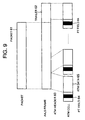
- Fig. 19 shows an example of rewriting a header transform table. This is an example of a header transform table for the port P3, including pairs of an input-side virtual connection identifier and output-side port identifier - virtual connection identifier.
- entries 71 and 72 correspond to the change from the virtual connection VC53 to the virtual connection VC53' in Figs. 4, 5, and 7. Namely, the entry 71 represents the virtual connection VC53, and the entry 72 the virtual connection VC53'.
- Fig. 17 illustrates an internal structure of the ATM interface section 242 on the input side, according to the present invention.
- a PT field monitoring section 2424 is newly added.
- Fig. 18 is a flowchart showing an example of a procedure for changing virtual connections using the PT field monitoring section. Between the step S4 and the Step S5 of Fig. 16, Step S6 and Step S7 are inserted. In Step 6, the ATM interface control section 2423 asks the PT field monitoring section 2424 if a cell with PT field value "1" has been processed. In Step 7, based on the response from the PT field monitoring section 2424, the interface control section 2423 judges if to proceed to Step 5.
- the PT field monitoring section 2424 may be provided with a function of investigating a cell flow and a timer function, by replacing it with a PT field monitoring section 2424a and a cell flow monitoring section 2424b (Fig. 27).
- a virtual connection change request arrives between packets, if the cell counting section 2424b does not count a cell flow for a given period of time, it is possible to change virtual connections without awaiting processing of a subsequent packet.
- Fig. 12 is a sequence diagram showing basic operation of the present invention.
- the packet D shown in Fig. 12 is a packet sent following the packet C.
- a virtual connection change request G2 arrives after a cell C1 has been processed.
- the switch section 24 resets the virtual connection VC53, which, at this point in time, is destined for the cell-to-packet assembly section 22 of the node 2, so that the virtual connection VC53 is destined for the cell-to-packet assembly section 12B of the node 1B, in addition to the cell-to-packet assembly section 22, by a multicast function.
- the operation can be seen from Fig. 12 by noting a multicast period W2.
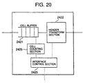
- Fig. 20 is a view illustrating an internal structure of the ATM interface section 242 on the input side, according to the present invention. It differs from Fig. 17 in that the PT field monitoring section 2424 is replaced by a cell counting section 2425.
- Fig. 21 is a flowchart showing an example of a procedure for changing virtual connections using the cell counting section. It is the same as Fig. 18 up to Step S4. Thereafter, the ATM interface control section 2423, which has received the virtual connection change request from the switch control section 243, rewrites the table of the header transform section 2422 so that, while maintaining the virtual connection before the change, the same cell is also multicasted onto the virtual connection after the change (Step S8). Then, the ATM interface control section 2423 inquires of the cell counting section 2425 about the current number of cells (Step S9). Based on a response from the cell counting section 2425, the interface control section 2423 judges if a given number of cells have been processed (Step S10). Judging that the given number of cells have been processed, the interface control section 2423 eliminates an entry representing the virtual connection before the change from the table of the header transform section 2422 (Step S11), completing the processing of changing the virtual connections.
- Fig. 22 shows an example of rewriting the head transform table in the multicast system. It differs from Fig. 19 in that there exists a period of multicast processing as shown by an entry 73. Some cells disassembled from the packet C generated in the sending node 1A arrive at the receiving node 1B in duplicate. A larger number of the duplicate cells is preferred for preventing packet loss and retransmission due to packet loss. On the other hand, from the viewpoint of packet processing in the IP switch and a transfer rate of the network, it is more desirable if a smaller number of cells are transferred in duplicate, i.e., multicasted.
- the maximum length of packets generally used in an IP network system i.e., 1500 byte
- This number 1500 is divided by 48 bytes, the length of the payload of the ATM cell, raised to a unit, and added with the length of 1 cell of the AAL5 trailer, giving 32, which may be considered an effective value of the given number for cells.
- the maximum length of packets in AAL5 is taken, 1,367 may be considered as the effective value.
- Fig. 13 is basically similar to Fig. 12 except that a multicast period W3 is fixed as a given period of time, with its length not being dynamically changed depending on the number of cells.
- Fig. 23 is a view illustrating an internal structure of the ATM interface section 242 on the input side, according to the present invention. Differently from Figs. 17 and 20, a timer section 2426 is provided, and the cell buffer is not monitored.
- Fig. 24 is a flowchart showing an example of a procedure for changing virtual connections in the present embodiment. It is similar to Fig. 21 except that the timer section 2426 is started up, instead of the cell counting section 2425 (Step S12), and that, awaiting the timer expiration, which is notified by a signal from the timer section 2426 (Step 13), the virtual connection before the change is eliminated.
- Fig. 25 shows an internal structure of the switch section 24, according to the present invention. Differently from the embodiments described heretofore, a timer section 245 is connected to the switch control section 243. By this construction, it is not necessary to add a new structure to the ATM interface section 242.
- Fig. 26 is a flowchart showing an example of a procedure for changing virtual connections. It is the same as the above-described flowcharts up to Step S2.
- the switch control section 243 which has received a virtual connection change request, sends a request for setting a virtual connection after the change to the ATM interface section 242 (Step S14).
- the interface control section 2423 within the interface section 242 rewrites the table of the header transform section 242 in accordance with the request.
- virtual connections are generated for multicasting both to the virtual connection before the change and to the virtual connection after the change (Step S15).
- the switch control section 243 starts up the timer section 245 (Step S16), and awaits a timer expiration signal (Step S17). When the timer expires, then, the switch control section 243 sends a request for eliminating the virtual connection before the change to the ATM interface section (Step S18). On receiving the request, the interface control section 2423 within the interface section eliminates the entry related to the virtual connection before the change from the table of the header transform section 2422 (Step S19), completing the process of changing the virtual connections.
- the first invention it is possible to prevent packet loss at the time of changing virtual connections.
- the second invention it is possible to prevent packet loss at the time of changing virtual connections.
- the invention can be implemented without addition of special hardware.
- this system does not require any circuit for high speed processing such as searching of the cell buffer's contents, and has a high degree of freedom in its construction.
Abstract
Description
Advantageously, this system does not require any circuit for high speed processing such as searching of the cell buffer's contents, and has a high degree of freedom in its construction.
Claims (44)
- A switch device comprising.a receiving port which receives cells from a data sending device;a switch section which switches the cells received through said receiving port;a cell-to-packet transform section which receives, through said switch section, the cells received by said receiving port, and assembles said cells into a packet;a packet processing section which processes said packet transformed from the cells by said cell-to-packet transform section;a packet-to-cell transform section which disassembles the packet processed by said packet processing section into cells and sends said cells to said switch section; anda sending port which receives the cells sent from said packet-to-cell transform section through said switch section, and sends said cells to a data receiving device; wherein:said switch section sets, for packet processing, a first virtual connection leading through said cell-to-packet transform section, said packet processing section, and said packet-to-cell transform section, and a second virtual connection for switching the cells received by said receiving port so as to send said cells to said sending port; andwhen virtual connection for transmitting cells is changed from said first virtual connection to said second virtual connection based on a connection change request from said data receiving device, said switch section sends cells via said first virtual connection until cells which constitute at least one packet of data have been switched.
- The switch device according to Claim 1, wherein:said packet processing section sends a virtual connection change request to said switch section, based on the connection change request from said data receiving device.
- The switch device according to Claim 2, wherein:said switch section comprises:a field monitoring section which monitors a specific field within a header of a received cell; anda header transform section which transforms a header of a received cell for changing said first virtual connection to said second virtual connection, based on said virtual connection change request, after the switch section receives said virtual connection change request, and after said field monitoring section detects that a value of a specific field within a header of a received cell indicates a final cell of a packet in question.
- The switch device according to Claim 3, wherein:said switch section further comprises:a cell counting section which counts a number of cells received after said virtual connection change request is received; anda header transform section which transforms a header of a received cell for changing virtual connection for transmitting cells from said first virtual connection to said second virtual connection, after a number of cells counted by said cell counting section becomes a given value.
- The switch device according to Claim 3, wherein:said switch section further comprises a timer which measures time until receiving a cell constituting a new packet; andsaid header transform section transforms a header of a received cell for changing said first virtual connection to said second virtual connection after said timer measures a given period of time.
- A switch device comprising:a receiving port which receives cells from a data sending device;a switch section which switches the cells received through said receiving port;a cell-to-packet transform section which receives, through said switch section, the cells which have been received by said receiving port, and assembles said cells into a packet;a packet processing section which processes said packet transformed from the cells by said cell-to-packet transform section;a packet-to-cell transform section which disassembles the packet processed by said packet processing section into cells and sends said cells to said switch section; anda sending port which receives the cells sent from said packet-to-cell transform section through said switch section, and sends said cells to a data receiving device; wherein:said packet processing section sends, based on a request from said data receiving section, a virtual connection change request to said switch section for changing virtual connection for transmitting cells from a first virtual connection which leads through said packet processing section, to a second virtual connection which connects said receiving port with said sending port through said switch section and switches cells in a state received from said data sending device, andafter receiving said virtual connection change request, said switch section sends cells via said second virtual connection until cells which constitute at least one packet of data have been switched.
- The switch device according to Claim 6, wherein:said switch section comprises:a field monitoring section which monitors a specific field within a header of a received cell; anda header transform section which transforms a header of a received cell for changing said first virtual connection to said second virtual connection, based on said virtual connection change request, after the switch section receives said virtual connection change request, and after said field monitoring section detects that a value of a specific field within a header of a received cell indicates a final cell of a packet in question.
- The switch device according to Claim 6, wherein:said switch section comprises:a cell counting section which counts a number of cells received after said virtual connection change request is received; anda header transform section which transforms a header of a received cell for changing virtual connection for transmitting cells from said first virtual connection to said second virtual connection, after a number of cells counted by said cell counting section becomes a given value.
- The switch device according to Claim 7, wherein:said switch section further comprises a timer which measures time until receiving a cell constituting a new packet; andsaid header transform section transforms a header of a received cell for changing virtual connection for transmitting cells from said first virtual connection to said second virtual connection after said timer measures a given period of time.
- The switch device according to Claim 1, wherein:said switch section changes virtual connection for transmitting cells from said first virtual connection to said second virtual connection, at an end of a packet sent from said data sending device.
- The switch device according to Claim 6, wherein:said switch section changes virtual connection for transmitting cells from said first virtual connection to said second virtual connection, at an end of a packet sent from said data sending device.
- A switch device comprising:a receiving port which receives cells from a data sending device;a switch section which switches the cells received through said receiving port;a cell-to-packet transform section which receives, through said switch section, the cells received by said receiving port, and assembles said cells into a packet;a packet processing section which processes said packet transformed from the cells by said cell-to-packet transform section;a packet-to-cell transform section which disassembles the packet processed by said packet processing section into cells and sends said cells to said switch section; anda sending port which receives the cells sent from said packet-to-cell transform section through said switch section, and sends said cells to a data receiving device; wherein:in the course of transferring packet data using a first virtual connection for sending cells from said data sending device to said receiving section through said packet processing section, said packet processing section sends said switch section a virtual connection change request for changing virtual connection for transmitting cells from said first virtual connection to a second virtual connection which connects said receiving port with said sending port through said switch section, andafter receiving said virtual connection change request, said switch section multicasts cells received through said receiving port to said cell-to-packet transform section and to said sending port, until a number of cells constituting maximum packet length have been switched.
- The switch device according to Claim 12, wherein:said switch section comprises:a cell counting section which counts a number of cells received after said virtual connection change request is received; anda header transform section which transforms a header of a received cell for changing virtual connection for transmitting cells from said first virtual connection to said second virtual connection, after a number of cells counted by said cell counting section becomes a given value.
- The switch device according to Claim 13, wherein:said given value of the number of cells counted by said cell counting section lies in a range of 32 to 1367, as the number of cells received after receiving said virtual connection change request.
- An interface circuit used in an IP switch, comprising:a cell buffer for buffering received cells;a PT field monitoring section for monitoring a PT field within a header of a cell received;a header transform section for transforming a header of a cell received; andan interface control section for sending and receiving data to and from an outside.
- An interface circuit used in an IP switch, comprising:a cell buffer which buffers received cells;a cell counting section which counts a number of received cells by request from an outside;a header transform section which transforms a header of a cell received, after the number of cells counted by said cell counting section becomes a given value; andan interface control section which externally sends and receiving data.
- An interface circuit used in an IP switch, comprising:a cell buffer which buffers received cells;a timer which measures time until receiving cells constituting a.new packet;a header transform section which transforms a header of a cell received, after said timer measures a given period of time; andan interface control section which externally sends and receives data.
- An ATM switch used in an IP switch, comprising:a receiving port which receives cells;a sending port which sends the cells switched; anda switch section which sets a first virtual connection for sending said received cells through the sending port after packet processing of said received cells, and a second virtual connection for transferring said received cells to the sending port; wherein:when said first virtual connection is to be changed to said second virtual connection based on an external request, said switch section sends ATM cells via said first virtual connection until ATM cells which constitute at least one packet of data have been switched.
- The ATM switch according to Claim 18, comprising:a PT field monitoring section which monitors a PT field within a header of received cells; anda header transform section which transforms a header of a received cell for changing virtual connection for transmitting cells from said first virtual connection to said second virtual connection, after receiving said external request, and after said PT field monitoring section detects that a value of a PT field within a header of a received cell is "1".
- The ATM switch according to Claim 18, further comprising:a cell counting section which counts a number of cells received after receiving said request from the outside; anda header transform section which transforms a header of a cell received, for changing virtual connection for transmitting cells from said first virtual connection to said second virtual connection, after the number of cells counted by said cell counting section becomes a given value.
- The ATM switch according to Claim 19, wherein:said ATM switch further comprises a timer which measures time until receiving cells constituting a new packet; andsaid header transform section transforms a header of a cell received, for changing virtual connection for transmitting cells from said first virtual connection to said second virtual connection, after said timer measures a given period of time.
- An ATM switch used in an IP switch, comprising:a receiving port which receives cells;a sending port which sends the cells switched;a switch section which sets a first virtual connection for sending said received cells through the sending port after packet processing of said received cells, and a second virtual connection for transferring said received cells to the sending port; anda packet processing section which, based on a request from an outside, sends said switch section a virtual connection change request for changing virtual connection for transmitting cells from said first virtual connection which leads through said packet processing section, to said second virtual connection which connects said receiving port with said sending port through said switch section for switching depending on a state of ATM cells from said data sending device; wherein,after receiving said virtual connection change request, said switch section sends ATM cells via said second virtual connection until ATM cells which constitute at least one packet of data have been switched.
- The ATM switch according to Claim 22, wherein:said switch section comprises:a PT field monitoring section which monitors a PT field within a header of received cells; anda header transform section which transforms a header of a received cell for changing virtual connection for transmitting cells from said first virtual connection to said second virtual connection based on said virtual connection change request, after receiving said virtual connection change request, and after said PT field monitoring section detects that a value of a PT field within a header of a received cell is "1".
- The ATM switch according to Claim 22, wherein:said switch section comprises:a cell counting section which counts a number of cells received after receiving said virtual connection change request; anda header transform section which transforms a header of a cell received, for changing virtual connection for transmitting cells from said first virtual connection to said second virtual connection, after the number of cells counted by said cell counting section becomes a given value.
- The ATM switch according to Claim 24, wherein:said switch section further comprises a timer which measures time until receiving cells constituting a new packet; andsaid header transform section which transforms a header of a cell received, for changing virtual connection for transmitting cells from said first virtual connection to said second virtual connection, after said timer measures a given period of time.
- The ATM switch according to Claim 18, wherein:said switch section changes virtual connection for transmitting cells from said first virtual connection to said second virtual connection, at an end of a packet sent from said data sending device.
- The ATM switch according to Claim 22, wherein:said switch section changes virtual connection for transmitting cells from said first virtual connection to said second virtual connection, at an end of a packet sent from said data sending device.
- An ATM switch used in an IP switch, comprising:a receiving port which receives cells;a sending port which sends the cells switched; anda switch section which sets a first virtual connection for sending said received cells through the sending port after packet processing of said received cells, and a second virtual connection for transferring said received cells to the sending port; wherein:after receiving an external request for changing virtual connection from said first virtual connection to said second virtual connection, said switch section multicasts ATM cells received through said receiving port onto said first virtual connection and onto said second virtual connection, until a number of ATM cells constituting maximum packet length have been switched.
- The ATM switch according to Claim 28, wherein:said switch section comprises:a cell counting section which counts a number of cells received after receiving said request from the outside; anda header transform section which transforms a header of a cell received, for changing virtual connection for transmitting cells from said first virtual connection to said second virtual connection, after the number of cells counted by said cell counting section becomes a given value.
- The ATM switch according to claim 29, wherein:said given value of the number of cells counted by said cell counting section lies in a range of 32 to 1367, as the number of cells received after receiving said virtual connection change request.
- An IP switch network system, comprising:a data sending device which generates a packet of data, disassembles said packet of data into ATM cells, and sends said ATM cells;an IP switch which receives the ATM cells sent from said data sending device, and relays said ATM cells received; anda data receiving device which receives said ATM cells relayed by said IP switch, and assembles said ATM cells into the packet of data; wherein, said IP switch comprises:a receiving port which receives the ATM cells from the data sending device;a switch section which switches the ATM cells received through said receiving port;a cell-to-packet transform section which receives, through said switch section, the ATM cells which have been received by said receiving port, and assembles said ATM cells into a packet;a packet processing section which processes said packet transformed from the ATM cells by said cell-to-packet transform section;a packet-to-cell transform section which disassembles the packet processed by said packet processing section into ATM cells and sends said ATM cells to said switch section; anda sending port which receives the ATM cells sent from said packet-to-cell transform section through said switch section, and sends said ATM cells to said data receiving device;
and wherein:
said switch section sets, for packet processing, a first virtual connection leading through said cell-to-packet transform section, said packet processing section, and said packet-to-cell transform section, and a second virtual connection for switching the ATM cells received by said receiving port so as to send said ATM cells to said sending port; andwhen virtual connection is changed from said first virtual connection to said second virtual connection based on a connection change request from said data receiving device, said switch section sends ATM cells via said first virtual connection until ATM cells which constitute at least one packet of data have been switched. - The IP switch network system according to Claim 31, wherein:said packet processing section sends a virtual connection change request to said switch section, based on the connection change request from said data receiving device.
- The IP switch network system according to Claim 32, wherein:said switch section comprises:a PT field monitoring section which monitors a PT field within a header of received cells; anda header transform section which transforms a header of a received cell for changing virtual connection for transmitting cells from said first virtual connection to said second virtual connection based on said virtual connection change request, after receiving said virtual connection change request, and after said PT field monitoring section detects that a value of a PT field within a header of a received cell is "1".
- The IP switch network system according to Claim 32, wherein:said switch section comprises:a cell counting section which counts a number of cells received after receiving said virtual connection change request; anda header transform section which transforms a header of a cell received, for changing virtual connection for transmitting cells from said first virtual connection to said second virtual connection, after the number of cells counted by said cell counting section becomes a given value.
- The IP switch network system according to Claim 33, wherein:said switch section further comprises a timer which measures time until receiving cells constituting a new packet; andsaid header transform section transforms a header of a cell received, for changing said first virtual connection to said second virtual connection, after said timer measures a given period of time.
- An IP switch network system, comprising:a data sending device which generates a packet of data, disassembles said packet of data into ATM cells, and sends said ATM cells;an IP switch which receives the ATM cells sent from said data sending device, and relays said ATM cells received; anda data receiving device which receives said ATM cells relayed by said IP switch, and assembles said ATM cells into the packet of data; wherein, said IP switch comprises:a receiving port which receives the ATM cells from said data sending device;a switch section which switches the ATM cells received through said receiving port;a cell-to-packet transform section which receives, through said switch section, the ATM cells which have been received by said receiving port, and assembles said ATM cells into a packet;a packet processing section which processes said packet transformed from the ATM cells by said cell-to-packet transform section;a packet-to-cell transform section which disassembles the packet processed by said packet processing section into ATM cells and sends said ATM cells to said switch section; anda sending port which receives the ATM cells sent from said packet-to-cell transform section through said switch section, and sends said ATM cells to said data receiving device;
and wherein:
based on a request from said data receiving device, said packet processing section sends said switch section a virtual connection change request for changing virtual connection for transmitting cells from said first virtual connection for sending said data receiving device the ATM cells through said packet processing section, to said second virtual connection which connects said receiving port with said sending port through said switch section for switching depending on a state of the ATM cells from said data sending device; andafter receiving said virtual connection change request, said switch section sends ATM cells via said second virtual connection until ATM cells which constitute at least one packet of data have been switched. - The IP switch network system according to Claim 36, wherein:said switch section comprises:a PT field monitoring section which monitors a PT field within a header of received cells; anda header transform section which transforms a header of a received cell for changing virtual connection for transmitting cells from said first virtual connection to said second virtual connection based on said virtual connection change request, after receiving said virtual connection change request, and after said PT field monitoring section detects that a value of a PT field within a header of a received cell is "1".
- The IP switch network system according to Claim 36, in which:said switch section comprises:a cell counting section which counts a number of cells received after receiving said virtual connection change request; anda header transform section which transforms a header of a cell received, for changing virtual connection for transmitting cells from said first virtual connection to said second virtual connection, after the number of cells counted by said cell counting section becomes a given value.
- The IP switch network system according to Claim 37, wherein:said switch section comprises a timer which measures time until receiving cells constituting a new packet; andsaid header transform section transforms a header of a cell received, for changing virtual connection for transmitting cells from said first virtual connection to said second virtual connection, after said timer measures a given period of time.
- The IP switch network system according to Claim 31, wherein:said switch section changes virtual connection for transmitting cells from said first virtual connection to said second virtual connection, at an end of a packet sent from said data sending device.
- The IP switch network system according to Claim 36, wherein:said switch section changes virtual connection for transmitting cells from said first virtual connection to said second virtual connection, at an end of a packet sent from said data sending device.
- An IP switch network system, comprising:a data sending device which generates a packet of data, disassembles said packet of data into ATM cells, and sends said ATM cells;an IP switch which receives the ATM cells sent from said data sending device, and relays said ATM cells received; anda data receiving device which receives said ATM cells relayed by said IP switch, and assembles said ATM cells into the packet of data; wherein, said IP switch comprises:a receiving port which receives the ATM cells from said data sending device;a switch section which witches the ATM cells received through said receiving port;a cell-to-packet transform section which receives, through said switch section, the ATM cells which have been received by said receiving port, and assembles said ATM cells into a packet;a packet processing section for processing said packet transformed from the ATM cells by said cell-to-packet transform section;a packet-to-cell transform section which disassembles the packet processed by said packet processing section into ATM cells and sends said ATM cells to said switch section; anda sending port which receives the ATM cells sent from said packet-to-cell transform section through said switch section, and sends said ATM cells to said data receiving device;
and wherein:
in the course of transferring the ATM cells from said data sending device to said cell-to-packet transform section and transferring the packet data using a first virtual connection for sending the packet data from said packet-to-cell transform section to said receiving section, said packet processing section sends said switch section a virtual connection change request for changing virtual connection for transmitting cells from said first virtual connection to a second virtual connection which connects said receiving port with said sending port through said switch section, andafter receiving said virtual connection change request, said switch section multicasts ATM cells received through said receiving port to said cell-to-packet transform section and to said sending port, until a number of cells constituting maximum packet length have been switched. - The IP switch network system according to Claim 42, wherein:said switch section comprises:a cell counting section which counts a number of cells received after receiving said virtual connection change request; anda header transform section which transforms a header of a cell received, for changing virtual connection for transmitting cells from said first virtual connection to said second virtual connection, after the number of cells counted by said cell counting section becomes a given value.
- The IP switch network system according to Claim 42, wherein:said given value of the number of cells counted by said cell counting section lies in a range of 32 to 1367, as the number of cells received after receiving said virtual connection change request.
Applications Claiming Priority (3)
| Application Number | Priority Date | Filing Date | Title |
|---|---|---|---|
| JP344981/96 | 1996-12-25 | ||
| JP34498196A JPH10190733A (en) | 1996-12-25 | 1996-12-25 | Ip switch, interface circuit and atm switch used for the ip switch and ip switch network system |
| JP34498196 | 1996-12-25 |
Publications (3)
| Publication Number | Publication Date |
|---|---|
| EP0851635A2 true EP0851635A2 (en) | 1998-07-01 |
| EP0851635A3 EP0851635A3 (en) | 2001-09-05 |
| EP0851635B1 EP0851635B1 (en) | 2006-04-12 |
Family
ID=18373473
Family Applications (1)
| Application Number | Title | Priority Date | Filing Date |
|---|---|---|---|
| EP97122833A Expired - Lifetime EP0851635B1 (en) | 1996-12-25 | 1997-12-23 | IP switch, interface circuit and ATM switch used for IP switch, and IP switch network system |
Country Status (4)
| Country | Link |
|---|---|
| US (4) | US6304555B1 (en) |
| EP (1) | EP0851635B1 (en) |
| JP (1) | JPH10190733A (en) |
| DE (1) | DE69735663T2 (en) |
Cited By (6)
| Publication number | Priority date | Publication date | Assignee | Title |
|---|---|---|---|---|
| GB2353176A (en) * | 1999-05-10 | 2001-02-14 | Distrib Systems Res Inst The | Integrated IP network |
| GB2373150B (en) * | 2001-01-22 | 2004-07-14 | Fujitsu Ltd | Optical network, subscriber side optical transmission apparatus, and office side optical transmission apparatus |
| US7028100B2 (en) | 2000-07-12 | 2006-04-11 | The Distribution Systems Research Institute | Integrated information communication system for detecting and discarding external data packets that violate addressing rules |
| US7301952B2 (en) | 2000-04-06 | 2007-11-27 | The Distribution Systems Research Institute | Terminal-to-terminal communication connection control method using IP transfer network |
| US7440456B2 (en) | 2001-06-08 | 2008-10-21 | The Distribution Systems Research Institute | Terminal-to-terminal communication connection control system for IP full service |
| US8072979B2 (en) | 2002-06-07 | 2011-12-06 | The Distribution Systems Research Institute | Terminal-to-terminal communication control system for IP full service |
Families Citing this family (14)
| Publication number | Priority date | Publication date | Assignee | Title |
|---|---|---|---|---|
| JPH10190733A (en) * | 1996-12-25 | 1998-07-21 | Hitachi Ltd | Ip switch, interface circuit and atm switch used for the ip switch and ip switch network system |
| JP3609256B2 (en) * | 1998-05-19 | 2005-01-12 | 株式会社日立製作所 | Network management device, node device, and network management system |
| US20030210696A1 (en) * | 2002-04-25 | 2003-11-13 | Globespanvirata Incorporated | System and method for routing across segments of a network switch |
| KR100424651B1 (en) * | 2002-04-11 | 2004-03-25 | 삼성전자주식회사 | Data communication method using resource reservation |
| US7447739B1 (en) * | 2002-09-19 | 2008-11-04 | At&T Intellectual Property I, L.P. | Data and voice messaging system |
| US7209551B1 (en) * | 2002-09-19 | 2007-04-24 | Sbc Properties, L.P. | Provisioning unified messaging system services |
| US20050129031A1 (en) * | 2003-12-10 | 2005-06-16 | Robotham Robert E. | Method and apparatus for providing combined processing of packet and cell data |
| CN1997002B (en) * | 2006-01-06 | 2010-05-12 | 财团法人资讯工业策进会 | Compatible method, system and related switch for multi-fold expansion tree protocol |
| US8081572B1 (en) | 2006-01-11 | 2011-12-20 | Juniper Networks, Inc. | Hierarchical packet scheduling |
| US10248453B2 (en) | 2012-10-23 | 2019-04-02 | Red Hat Israel, Ltd. | Client live migration for a virtual machine |
| WO2014067470A1 (en) * | 2012-10-31 | 2014-05-08 | Hangzhou H3C Technologies Co., Ltd. | Port mode synchronization between switches |
| CN103795518B (en) * | 2012-10-31 | 2017-04-05 | 杭州华三通信技术有限公司 | A kind of equipment room port mode synchronous method, equipment and system |
| US9253043B2 (en) | 2013-11-30 | 2016-02-02 | At&T Intellectual Property I, L.P. | Methods and apparatus to convert router configuration data |
| TWI803687B (en) * | 2018-08-23 | 2023-06-01 | 美商阿爾克斯股份有限公司 | System for routing optimization and method thereof |
Citations (8)
| Publication number | Priority date | Publication date | Assignee | Title |
|---|---|---|---|---|
| EP0402471A1 (en) * | 1988-12-20 | 1990-12-19 | Institut Gidrodinamiki Imeni M.A. Lavrentieva Sibirskogo Otdelenia Akademii Nauk Sssr | Barrel of an installation for gas-detonation application of coatings |
| EP0502436A2 (en) * | 1991-03-05 | 1992-09-09 | Hitachi, Ltd. | ATM cell switching system |
| WO1992017014A1 (en) * | 1991-03-22 | 1992-10-01 | Gpt Limited | Connectionless switching for an atm switch |
| EP0554859A2 (en) * | 1992-02-06 | 1993-08-11 | Hitachi, Ltd. | ATM cell policing method and apparatus |
| EP0597487A2 (en) * | 1992-11-12 | 1994-05-18 | Nec Corporation | Asynchronous transfer mode communication system |
| US5359600A (en) * | 1992-02-14 | 1994-10-25 | Nippon Telegraph And Telephone Corporation | High throughput supervisory system for ATM switching systems transporting STM-N signals |
| GB2281005A (en) * | 1993-06-21 | 1995-02-15 | Plessey Telecomm | Network management to avoid congestion |
| US5678060A (en) * | 1993-10-28 | 1997-10-14 | Hitachi, Ltd. | System for executing high speed communication protocol processing by predicting protocol header of next frame utilizing successive analysis of protocol header until successful header retrieval |
Family Cites Families (30)
| Publication number | Priority date | Publication date | Assignee | Title |
|---|---|---|---|---|
| US4748658A (en) * | 1986-07-16 | 1988-05-31 | Bell Communications Research, Inc. | Architecture for allocating resources in a telecommunications network |
| US6049999A (en) * | 1987-02-13 | 2000-04-18 | Beloit Technologies, Inc. | Machine and process for the restrained drying of a paper web |
| US5072443A (en) * | 1989-07-28 | 1991-12-10 | At&T Bell Laboratories | Communications system |
| JP2950627B2 (en) | 1991-02-15 | 1999-09-20 | 株式会社日立製作所 | Subscriber line transmission path capacity display method in asynchronous transfer mode. |
| JP2782973B2 (en) * | 1991-04-10 | 1998-08-06 | 株式会社日立製作所 | Flow rate monitoring method and system in packet network |
| US5958339A (en) | 1992-08-31 | 1999-09-28 | Clinical Diagnostic Systems, Inc. | Format for immunoassay in thin film |
| US5426636A (en) * | 1993-12-20 | 1995-06-20 | At&T Corp. | ATM distribution networks for narrow band communications |
| JP3224963B2 (en) | 1994-08-31 | 2001-11-05 | 株式会社東芝 | Network connection device and packet transfer method |
| GB9512422D0 (en) | 1994-09-01 | 1995-08-23 | British Telecomm | Network management system for communications networks |
| US5764740A (en) * | 1995-07-14 | 1998-06-09 | Telefonaktiebolaget Lm Ericsson | System and method for optimal logical network capacity dimensioning with broadband traffic |
| JPH09181740A (en) | 1995-10-26 | 1997-07-11 | Hitachi Ltd | Method for controlling flow inside network node and packet switching system |
| JP3686493B2 (en) * | 1996-03-07 | 2005-08-24 | 富士通株式会社 | Feedback control method and apparatus in ATM switch |
| US6108304A (en) | 1996-03-08 | 2000-08-22 | Abe; Hajime | Packet switching network, packet switching equipment, and network management equipment |
| JPH10190733A (en) * | 1996-12-25 | 1998-07-21 | Hitachi Ltd | Ip switch, interface circuit and atm switch used for the ip switch and ip switch network system |
| JP3643637B2 (en) | 1996-03-08 | 2005-04-27 | 株式会社日立コミュニケーションテクノロジー | Cell output control circuit and control method |
| US5917820A (en) | 1996-06-10 | 1999-06-29 | Cisco Technology, Inc. | Efficient packet forwarding arrangement for routing packets in an internetwork |
| GB9612363D0 (en) | 1996-06-13 | 1996-08-14 | British Telecomm | ATM network management |
| JP3142485B2 (en) * | 1996-06-28 | 2001-03-07 | 沖電気工業株式会社 | Network control device |
| JPH1079740A (en) * | 1996-09-03 | 1998-03-24 | Hitachi Ltd | Router device using atm switch |
| US6046999A (en) * | 1996-09-03 | 2000-04-04 | Hitachi, Ltd. | Router apparatus using ATM switch |
| JPH10126439A (en) * | 1996-10-17 | 1998-05-15 | Fujitsu Ltd | Route selection device for packet exchange communication network |
| US5804496A (en) * | 1997-01-08 | 1998-09-08 | Advanced Micro Devices | Semiconductor device having reduced overlap capacitance and method of manufacture thereof |
| US6108340A (en) * | 1997-03-21 | 2000-08-22 | International Business Machines Corporation | Incidence graph based communications and operations method and apparatus for parallel processing architecture |
| WO1998045995A1 (en) * | 1997-04-09 | 1998-10-15 | Alcatel Australia Limited | Internet closed user group |
| JP3575225B2 (en) * | 1997-05-19 | 2004-10-13 | 株式会社日立製作所 | Packet switch, packet switching network, and packet switching method |
| US6667985B1 (en) * | 1998-10-28 | 2003-12-23 | 3Com Technologies | Communication switch including input bandwidth throttling to reduce output congestion |
| US6580723B1 (en) * | 1998-11-02 | 2003-06-17 | Cisco Technology, Inc. | Time slotted logical ring |
| US20030030679A1 (en) * | 2000-01-06 | 2003-02-13 | Anuj Kumar Jain | User-definable images in bookmarks |
| CA2344743C (en) * | 2001-04-20 | 2011-12-06 | Elysium Broadband Inc. | Point to multi-point communications system |
| US20030031239A1 (en) * | 2001-08-08 | 2003-02-13 | Posthuma Carl Robert | Maximizing DSL throughput |
-
1996
- 1996-12-25 JP JP34498196A patent/JPH10190733A/en active Pending
-
1997
- 1997-12-23 DE DE69735663T patent/DE69735663T2/en not_active Expired - Fee Related
- 1997-12-23 EP EP97122833A patent/EP0851635B1/en not_active Expired - Lifetime
- 1997-12-24 US US08/998,382 patent/US6304555B1/en not_active Expired - Fee Related
-
2001
- 2001-02-02 US US09/776,283 patent/US6526045B2/en not_active Expired - Fee Related
-
2003
- 2003-02-19 US US10/370,285 patent/US6993029B2/en not_active Expired - Fee Related
-
2004
- 2004-07-14 US US10/891,293 patent/US20040264460A1/en not_active Abandoned
Patent Citations (8)
| Publication number | Priority date | Publication date | Assignee | Title |
|---|---|---|---|---|
| EP0402471A1 (en) * | 1988-12-20 | 1990-12-19 | Institut Gidrodinamiki Imeni M.A. Lavrentieva Sibirskogo Otdelenia Akademii Nauk Sssr | Barrel of an installation for gas-detonation application of coatings |
| EP0502436A2 (en) * | 1991-03-05 | 1992-09-09 | Hitachi, Ltd. | ATM cell switching system |
| WO1992017014A1 (en) * | 1991-03-22 | 1992-10-01 | Gpt Limited | Connectionless switching for an atm switch |
| EP0554859A2 (en) * | 1992-02-06 | 1993-08-11 | Hitachi, Ltd. | ATM cell policing method and apparatus |
| US5359600A (en) * | 1992-02-14 | 1994-10-25 | Nippon Telegraph And Telephone Corporation | High throughput supervisory system for ATM switching systems transporting STM-N signals |
| EP0597487A2 (en) * | 1992-11-12 | 1994-05-18 | Nec Corporation | Asynchronous transfer mode communication system |
| GB2281005A (en) * | 1993-06-21 | 1995-02-15 | Plessey Telecomm | Network management to avoid congestion |
| US5678060A (en) * | 1993-10-28 | 1997-10-14 | Hitachi, Ltd. | System for executing high speed communication protocol processing by predicting protocol header of next frame utilizing successive analysis of protocol header until successful header retrieval |
Non-Patent Citations (1)
| Title |
|---|
| BURAK M: "CONNECTIONLESS SERVICES IN AN ATM-LAN PROVIDED BY A CL-SERVER AN IMPLEMENTATION AND CASE STUDY" PROCEEDINGS OF THE GLOBAL TELECOMMUNICATIONS CONFERENCE (GLOBECOM),US,NEW YORK, IEEE, 28 November 1994 (1994-11-28), pages 1827-1831, XP000497985 ISBN: 0-7803-1821-8 * |
Cited By (18)
| Publication number | Priority date | Publication date | Assignee | Title |
|---|---|---|---|---|
| GB2353176A (en) * | 1999-05-10 | 2001-02-14 | Distrib Systems Res Inst The | Integrated IP network |
| US6711623B1 (en) | 1999-05-10 | 2004-03-23 | The Distribution Systems Research Institute | Integrated IP network |
| GB2353176B (en) * | 1999-05-10 | 2004-05-26 | Distrib Systems Res Inst The | Integrated IP network |
| US7373429B2 (en) | 1999-05-10 | 2008-05-13 | The Distribution Systems Research Institute | Integrated IP network |
| US8948161B2 (en) | 2000-04-06 | 2015-02-03 | The Distribution Systems Research Institute | Terminal-to-terminal communication connection control method using IP transfer network |
| US7301952B2 (en) | 2000-04-06 | 2007-11-27 | The Distribution Systems Research Institute | Terminal-to-terminal communication connection control method using IP transfer network |
| US8553677B2 (en) | 2000-04-06 | 2013-10-08 | The Distribution Systems Research Institute | Terminal to-terminal communication connection control method using IP transfer network |
| US8934484B2 (en) | 2000-04-06 | 2015-01-13 | The Distribution Systems Research Institute | Terminal-to-terminal communication connection control method using IP transfer network |
| US7505471B2 (en) | 2000-04-06 | 2009-03-17 | The Distribution Systems Research Institute | Terminal-to-terminal communication connection control method using IP transfer network |
| US7733882B2 (en) | 2000-04-06 | 2010-06-08 | The Distribution Systems Research Institute | Terminal-to-terminal communication connection control method using IP transfer network |
| US7782883B2 (en) | 2000-04-06 | 2010-08-24 | The Distribution Systems Research Institute | Terminal-to-terminal communication connection control method using IP transfer network |
| US7948995B2 (en) | 2000-04-06 | 2011-05-24 | The Distribution Systems Research Institute | Terminal-to-terminal communication connection control method using IP transfer network |
| US8565245B2 (en) | 2000-04-06 | 2013-10-22 | The Distribution Systems Research Institute | Terminal-to-terminal communication connection control method using IP transfer network |
| US8121113B2 (en) | 2000-04-06 | 2012-02-21 | The Distribution Systems Research Institute | Terminal-to-terminal communication connection control method using IP transfer network |
| US7028100B2 (en) | 2000-07-12 | 2006-04-11 | The Distribution Systems Research Institute | Integrated information communication system for detecting and discarding external data packets that violate addressing rules |
| GB2373150B (en) * | 2001-01-22 | 2004-07-14 | Fujitsu Ltd | Optical network, subscriber side optical transmission apparatus, and office side optical transmission apparatus |
| US7440456B2 (en) | 2001-06-08 | 2008-10-21 | The Distribution Systems Research Institute | Terminal-to-terminal communication connection control system for IP full service |
| US8072979B2 (en) | 2002-06-07 | 2011-12-06 | The Distribution Systems Research Institute | Terminal-to-terminal communication control system for IP full service |
Also Published As
| Publication number | Publication date |
|---|---|
| JPH10190733A (en) | 1998-07-21 |
| US20010005383A1 (en) | 2001-06-28 |
| DE69735663D1 (en) | 2006-05-24 |
| EP0851635A3 (en) | 2001-09-05 |
| US20030152085A1 (en) | 2003-08-14 |
| US6526045B2 (en) | 2003-02-25 |
| EP0851635B1 (en) | 2006-04-12 |
| US6304555B1 (en) | 2001-10-16 |
| US20040264460A1 (en) | 2004-12-30 |
| US6993029B2 (en) | 2006-01-31 |
| DE69735663T2 (en) | 2007-05-03 |
Similar Documents
| Publication | Publication Date | Title |
|---|---|---|
| EP0851635B1 (en) | IP switch, interface circuit and ATM switch used for IP switch, and IP switch network system | |
| US7385967B2 (en) | Network interconnection apparatus, network node apparatus, and packet transfer method for high speed, large capacity inter-network communication | |
| US6222839B1 (en) | Packet switching apparatus | |
| JP4436981B2 (en) | ECN-based method for managing congestion in a hybrid IP-ATM network | |
| US5345558A (en) | Topology independent broadcast of cells in an ATM network or the like | |
| EP0869695B1 (en) | System for routing packet switched traffic | |
| JP3607466B2 (en) | Router device and control frame processing method | |
| JP3682082B2 (en) | Apparatus and method for packet processing in packet switching network and frame processing system for frame relay network | |
| US6018530A (en) | Method for transmitting using a modified transport control protocol | |
| US5511076A (en) | Method and apparatus to efficiently reuse virtual connections by means of chaser packets | |
| US6970478B1 (en) | Packet transfer method and apparatus, and packet communication system | |
| JP3923533B2 (en) | ATM partial cut-through | |
| KR100298357B1 (en) | Frame relay-to-atm interface circuit and method of operation | |
| US6256323B1 (en) | Method and apparatus for efficiently transporting asynchronous characters over an ATM network | |
| WO2000056113A1 (en) | Internet protocol switch and method | |
| JP2991501B2 (en) | How to reroute packet mode data connections | |
| US6216166B1 (en) | Shared media communications in a virtual connection network | |
| WO1998024262A1 (en) | Scaleable data network router | |
| JP4087408B2 (en) | Packet transfer method and apparatus | |
| Cisco | Configuring X.25 and LAPB | |
| Cisco | Wide-Area Networking Configuration Guide Cisco IOS Release 11.3 | |
| AU4387197A (en) | Packet routing in a telecommunications network | |
| JP3715541B2 (en) | ATM connection device | |
| JP3471136B2 (en) | Control information transfer method and node device | |
| GB2320396A (en) | Data network router |
Legal Events
| Date | Code | Title | Description |
|---|---|---|---|
| PUAI | Public reference made under article 153(3) epc to a published international application that has entered the european phase |
Free format text: ORIGINAL CODE: 0009012 |
|
| AK | Designated contracting states |
Kind code of ref document: A2 Designated state(s): AT BE CH DE DK ES FI FR GB GR IE IT LI LU MC NL PT SE Kind code of ref document: A2 Designated state(s): DE FR GB |
|
| AX | Request for extension of the european patent |
Free format text: AL;LT;LV;MK;RO;SI |
|
| PUAL | Search report despatched |
Free format text: ORIGINAL CODE: 0009013 |
|
| AK | Designated contracting states |
Kind code of ref document: A3 Designated state(s): AT BE CH DE DK ES FI FR GB GR IE IT LI LU MC NL PT SE |
|
| AX | Request for extension of the european patent |
Free format text: AL;LT;LV;MK;RO;SI |
|
| 17P | Request for examination filed |
Effective date: 20020108 |
|
| AKX | Designation fees paid |
Free format text: DE FR GB |
|
| 17Q | First examination report despatched |
Effective date: 20041014 |
|
| GRAP | Despatch of communication of intention to grant a patent |
Free format text: ORIGINAL CODE: EPIDOSNIGR1 |
|
| GRAS | Grant fee paid |
Free format text: ORIGINAL CODE: EPIDOSNIGR3 |
|
| GRAA | (expected) grant |
Free format text: ORIGINAL CODE: 0009210 |
|
| RAP1 | Party data changed (applicant data changed or rights of an application transferred) |
Owner name: HITACHI, LTD. |
|
| AK | Designated contracting states |
Kind code of ref document: B1 Designated state(s): DE FR GB |
|
| REG | Reference to a national code |
Ref country code: GB Ref legal event code: FG4D |
|
| REF | Corresponds to: |
Ref document number: 69735663 Country of ref document: DE Date of ref document: 20060524 Kind code of ref document: P |
|
| ET | Fr: translation filed | ||
| PLBE | No opposition filed within time limit |
Free format text: ORIGINAL CODE: 0009261 |
|
| STAA | Information on the status of an ep patent application or granted ep patent |
Free format text: STATUS: NO OPPOSITION FILED WITHIN TIME LIMIT |
|
| 26N | No opposition filed |
Effective date: 20070115 |
|
| PG25 | Lapsed in a contracting state [announced via postgrant information from national office to epo] |
Ref country code: DE Free format text: LAPSE BECAUSE OF NON-PAYMENT OF DUE FEES Effective date: 20070703 |
|
| GBPC | Gb: european patent ceased through non-payment of renewal fee |
Effective date: 20061223 |
|
| REG | Reference to a national code |
Ref country code: FR Ref legal event code: ST Effective date: 20070831 |
|
| PG25 | Lapsed in a contracting state [announced via postgrant information from national office to epo] |
Ref country code: GB Free format text: LAPSE BECAUSE OF NON-PAYMENT OF DUE FEES Effective date: 20061223 |
|
| PG25 | Lapsed in a contracting state [announced via postgrant information from national office to epo] |
Ref country code: FR Free format text: LAPSE BECAUSE OF NON-PAYMENT OF DUE FEES Effective date: 20070102 |