EP0851374A1 - Method of locating an object-applied code - Google Patents

Method of locating an object-applied code Download PDF

Info

Publication number
EP0851374A1
EP0851374A1 EP96830661A EP96830661A EP0851374A1 EP 0851374 A1 EP0851374 A1 EP 0851374A1 EP 96830661 A EP96830661 A EP 96830661A EP 96830661 A EP96830661 A EP 96830661A EP 0851374 A1 EP0851374 A1 EP 0851374A1
Authority
EP
European Patent Office
Prior art keywords
vectors
subimages
gradient vector
gradient
code
Prior art date
Legal status (The legal status is an assumption and is not a legal conclusion. Google has not performed a legal analysis and makes no representation as to the accuracy of the status listed.)
Granted
Application number
EP96830661A
Other languages
German (de)
French (fr)
Other versions
EP0851374B1 (en
Inventor
Claudio Saporetti
Current Assignee (The listed assignees may be inaccurate. Google has not performed a legal analysis and makes no representation or warranty as to the accuracy of the list.)
Datalogic SpA
Original Assignee
Datalogic SpA
Priority date (The priority date is an assumption and is not a legal conclusion. Google has not performed a legal analysis and makes no representation as to the accuracy of the date listed.)
Filing date
Publication date
Application filed by Datalogic SpA filed Critical Datalogic SpA
Priority to AT96830661T priority Critical patent/ATE249650T1/en
Priority to EP96830661A priority patent/EP0851374B1/en
Priority to DE69629930T priority patent/DE69629930T2/en
Priority to US09/000,797 priority patent/US6047893A/en
Publication of EP0851374A1 publication Critical patent/EP0851374A1/en
Application granted granted Critical
Publication of EP0851374B1 publication Critical patent/EP0851374B1/en
Anticipated expiration legal-status Critical
Expired - Lifetime legal-status Critical Current

Links

Images

Classifications

    • GPHYSICS
    • G06COMPUTING; CALCULATING OR COUNTING
    • G06KGRAPHICAL DATA READING; PRESENTATION OF DATA; RECORD CARRIERS; HANDLING RECORD CARRIERS
    • G06K7/00Methods or arrangements for sensing record carriers, e.g. for reading patterns
    • G06K7/10Methods or arrangements for sensing record carriers, e.g. for reading patterns by electromagnetic radiation, e.g. optical sensing; by corpuscular radiation
    • G06K7/14Methods or arrangements for sensing record carriers, e.g. for reading patterns by electromagnetic radiation, e.g. optical sensing; by corpuscular radiation using light without selection of wavelength, e.g. sensing reflected white light
    • G06K7/1404Methods for optical code recognition
    • G06K7/146Methods for optical code recognition the method including quality enhancement steps
    • G06K7/1478Methods for optical code recognition the method including quality enhancement steps adapting the threshold for pixels in a CMOS or CCD pixel sensor for black and white recognition
    • GPHYSICS
    • G06COMPUTING; CALCULATING OR COUNTING
    • G06KGRAPHICAL DATA READING; PRESENTATION OF DATA; RECORD CARRIERS; HANDLING RECORD CARRIERS
    • G06K7/00Methods or arrangements for sensing record carriers, e.g. for reading patterns
    • G06K7/10Methods or arrangements for sensing record carriers, e.g. for reading patterns by electromagnetic radiation, e.g. optical sensing; by corpuscular radiation
    • G06K7/14Methods or arrangements for sensing record carriers, e.g. for reading patterns by electromagnetic radiation, e.g. optical sensing; by corpuscular radiation using light without selection of wavelength, e.g. sensing reflected white light

Abstract

A method wherein an image (I) of an object bearing an optical code is divided (120) into a number of elementary images (If) for which a brightness gradient vector (G) is calculated (130). The calculated gradients (G) of a magnitude above (140) a given threshold value (Glim) are transformed (190) to eliminate the information relative to the direction of the vector, while maintaining the information relative to the path of the vector. The transformed (190) and quantized (200) vectors of a subimage (Ip) including a number of elementary images (If) are added (220) to calculate a total gradient vector, which is compared (230) with reference values to select (240) significant subimages containing a sufficient number of gradient vectors of substantially the same path.

Description

The present invention relates to a method of locating an object-applied optical code.
The present invention also relates to a device implementing the above method.
Systems are known for locating optical codes - in particular bar codes - applied to objects traveling on conveying devices (e.g. conveyor belts), and for determining the presence and arrangement in space of the code. Known devices normally use laser locating and reading systems, known types of which, however, present several drawbacks: poor reliability, due to the large number of moving mechanical parts involved; limited omnidirectional reading capacity; inability to read two-dimensional codes; and poor capacity for reading plastic-coated codes.
To overcome the above drawbacks, systems have been devised featuring optical sensors (in particular, telecameras) for picking up a two-dimensional image of the object and selecting a portion of the image corresponding to the code. Such systems also provide for reading the code in the selected image portion, but suffer from the drawback of involving complex processing of a large amount of data.
It is an object of the present invention to provide a method of locating an object-applied optical code, which provides for fast, effective location of the code.
According to the present invention, there is provided a method of locating an optical code applied to an object, characterized by comprising: an image acquisition step wherein at least one image (I) of an object bearing said code is acquired; a first processing step wherein the acquired image (I) is divided into a number of elementary images (If), each comprising a predetermined number (N) of pixels, and each pixel being assigned a pixel brightness value; a second processing step wherein a brightness gradient vector (G) is calculated for each of said elementary images (If); a first comparing step wherein, from said calculated gradient vectors (G), the vectors of a magnitude above at least one threshold value (Glim) and representing rapid variations in brightness are selected; a transforming step wherein the previously selected gradient vectors are transformed to determine a given path and a given direction, which path and which direction are assigned to all the calculated gradient vectors; a tiling step wherein said acquired image (I) is divided into a number of subimages (Ip), each comprising a number of elementary images (If); a composing step wherein the previously transformed gradient vectors of a selected subimage (Ip) are added to calculate a total gradient vector (Gs); a second comparing step wherein said total gradient vector (Gs) of each of said subimages (Ip) is compared with reference values to select significant subimages containing a sufficient number of gradient vectors having substantially the same path; the significant subimages being assigned a first binary logic value; said second comparing step also determining nonsignificant subimages containing a limited number of gradient vectors having substantially the same path; the nonsignificant subimages being assigned a second binary logic value; and said method generating at least one final binary image (Ir) representing said acquired image (I) divided into said subimages (Ip), each having a respective binary logic value.
If the optical code is a bar code, the angle (α) formed by said gradient vector with a cartesian reference system is preferably doubled during said transforming step.
During said transforming step, the angle (α) formed by said gradient vector with a cartesian reference system is preferably multiplied by a factor equal to the number of sides of the geometric figure forming the unit element of the optical code. More specifically, if the optical code is a two-dimensional code, the unit element of which is defined by four sides, said angle (α) is multiplied by a factor of four; if the unit element is defined by six sides, said angle (α) is multiplied by a factor of six.
The method according to the present invention provides for rapidly and effectively locating the acquired image portion corresponding to the code, so that the code reading algorithm only operates on the portions corresponding to the optical code image, and the amount of information for processing is greatly reduced as compared with that picked up by the telecamera. Moreover, no information is lost due to elision of vectors having the same path but opposite directions.
According to the present invention, there is also provided a device for locating an optical code applied to an object, characterized by comprising: image acquisition means for acquiring at least one image (I) of an object bearing said code; first processing means wherein the acquired image (I) is divided into a number of elementary images (If), each comprising a predetermined number (N) of pixels, and each pixel being assigned a pixel brightness value; second processing means wherein a brightness gradient vector (G) is calculated for each of said elementary images (If); first comparing means wherein, from said calculated gradient vectors (G), the vectors of a magnitude above at least one threshold value (Glim) and representing rapid variations in brightness are selected; transforming means wherein the previously selected gradient vectors are transformed to determine a given path and a given direction, which path and which direction are assigned to all the calculated gradient vectors; tiling means wherein said acquired image (I) is divided into a number of subimages (Ip), each comprising a number of elementary images (If); composing means wherein the previously transformed gradient vectors of a selected subimage (Ip) are added to calculate a total gradient vector (Gs); second comparing means wherein said total gradient vector (Gs) of each of said subimages (Ip) is compared with reference values to select significant subimages containing a sufficient number of gradient vectors having substantially the same path; the significant subimages being assigned a first binary logic value; said second comparing means also determining nonsignificant subimages containing a limited number of gradient vectors having substantially the same path; the nonsignificant subimages being assigned a second binary logic value; and said device generating at least one final binary image (Ir) representing said acquired image (I) divided into said subimages (Ip), each having a respective binary logic value.
If said code is a bar code, the transforming means preferably double the angle (α) formed by said gradient vector with a reference system.
Said transforming means preferably multiply the angle (α) formed by said gradient vector with a cartesian reference system by a factor equal to the number of sides of the geometric figure forming the unit element of the optical code. More specifically, if the optical code is a two-dimensional code, the unit element of which is defined by four sides, the factor equals four; if the optical code is a two-dimensional code, the unit element of which is defined by six sides, the factor equals six.
A number of non-limiting embodiments of the present invention will be described by way of example with reference to the accompanying drawings, in which:
  • Figure 1 shows a schematic view of an automatic reading device implementing the method according to the present invention;
  • Figure 2 shows a circuit block diagram of a detail of the Figure 1 device;
  • Figure 3 shows the steps in the method according to the present invention;
  • Figures 4 to 12 show how the code locating method according to the teachings of the present invention operates.
  • Number 1 in Figure 1 indicates an automatic optical code reading device comprising a reading head 5 facing a conveyor belt 6 and for scanning objects 7 located on conveyor belt 6, traveling in a straight horizontal direction D, and each bearing an optical code on the surface 7a facing reading head 5. The term "optical code" is intended to mean a set of graphic marks on a label or directly on the object (or any other support), whereby information is coded in the form of a sequence of black and white or variously coloured regions arranged in one or more directions. Examples of optical codes are bar, two-dimensional and colour codes.
    In the example shown, object 7 comprises a bar code BC in the form of a number of straight, parallel, alternating light and dark bars.
    Device 1 comprises an electronic processing and control unit 12 cooperating with reading head 5.
    Device 1 also comprises a sensor 14 located along conveyor belt 6 to determine the height of objects 7 traveling along the belt; a sensor 15 for determining the presence of objects 7 in the vicinity of reading head 5; and a speed sensor 16 for determining the traveling speed of the belt (and hence the conveyed objects) with respect to reading head 5.
    Device 1 also comprises a lighting device 17 for lighting the belt portion scanned by reading head 5.
    With reference to Figure 2, reading head 5 comprises a linear (e.g. CCD) telecamera 20 for scanning a line 6a of the belt (either continuously or when enabled by sensors 14, 15 and 16); and a circuit 22 for processing the output signals generated by telecamera 20. Circuit 22 comprises a filter 24 connected at the input to the output of telecamera 20; an image memory 26 connected at the input to the output of telecamera 20; and a programmable data processing unit (digital signal processor - DSP) 28 cooperating with filter 24 and memory 26.
    Figure 3 shows a block diagram of the operating cycle of processing circuit 22.
    More specifically, and as shown in Figure 3, a start block 100 goes on to a block 110, in which the lines 6a scanned by telecamera 20 are composed electronically to form a two-dimensional image (stored in memory 26) of conveyor belt 6 and/or objects 7, and so form a digital image I comprising a matrix of pixels, each characterized by a whole number defining its grey level. The acquired digital image I may comprise one or more objects 7 on conveyor belt 6, bearing one or more optical codes.
    Block 110 is followed by a block 120, in which the acquired digital image I is divided into a number of elementary images (windows) If, each comprising a predetermined number N of pixels.
    For example, windows If may comprise four pixels, as shown in Figure 4.
    Block 120 is followed by a block 130, in which a brightness gradient vector G is calculated for each window If of image I.
    In the example shown (four-pixel window), if A, B, C and D are the respective numeric values of the brightness of the pixels in the window, the gradient vector is calculated according to the following equations: GX = C - B GY = D - A α = arctg(GY/GX) where GX and GY are the components of gradient vector G along the X and Y axes (Figure 4), and α is the angle between the gradient and the X axis of a cartesian reference system, in which the X axis extends along the diagonals of pixels B,C, and the Y axis along the diagonals of pixels A,D.
    Block 130 is followed by a block 140, which compares the magnitude of each calculated gradient vector with a threshold value Glim established at the initialization step. If the value of the gradient vector is below the threshold, block 140 goes on to a block 150, in which the gradient vector, considered nonsignificant by representing only gradual variations in brightness, is cancelled. Conversely (block 190 following block 140), the calculated gradient vector, considered significant by representing sharp variations in brightness, is kept for subsequent processing.
    Block 190 performs a so-called "S-transform" of each previously calculated and selected gradient vector. More specifically, if the optical code is a bar code, angle α of each gradient vector is doubled (Figure 5).
    The transformation operator in block 190 is capable of passing from gradient space (defined by magnitude, path and direction) to path space (defined by magnitude and path), so that, when S-transformed, two gradients of the same magnitude and path but opposite directions are mapped in the same path space vector. If the S-transform were not performed, in fact, the mean of two vectors of the same magnitude and path but opposite directions would obviously give a zero result, and the information associated with the gradients would be lost. To locate a bar code, which comprises a number of black bars alternating with white spaces, both black to white and white to black transitions, i.e. vectors of opposite directions, must be taken into account.
    Two gradient vectors G1 and G2 of the same magnitude and path but opposite directions have the same magnitude |G| and respective angles α1 and α2, where α2 = α1 +180°. When S-transformed, the angle of vector G1 equals 2α1, and the angle of vector G2 equals 2 = 2(α1 +180°) = 2α1 + 360°, i.e. vector G1 is now parallel to vector G2 and has the same direction.
    Other two-dimensional optical codes, such as so-called "ID-MATRIX" codes, comprise square black or white unit elements, and involve identifying changes in brightness from white to black and black to white in four perpendicular directions, i.e. identifying four gradient vectors of the same magnitude and at 90° to one another (i.e. having respective angles α, α+90°, α+180°, α+270°). In this case, the S-transform in block 190 multiplies the angles of the four gradient vectors by 4 to generate four gradients, all with the same path 4α; and the four S-transformed vectors are added to give a vector of four times the magnitude of the gradient vectors and path 4α.
    Other two-dimensional codes, such as "MAXICODES", comprise hexagonal black or white unit elements, and involve identifying changes in brightness from white to black and black to white in six directions to give six gradient vectors of the same magnitude and at 60° to one another (i.e. having respective angles α, α+60°, α+120°, α+180°, α+240°, α+300°). In this case, the S-transform in block 190 multiplies the angles of the six gradient vectors by 6 to generate six gradients, all with the same path 6α; and the six S-transformed vectors are added to give a vector of six times the magnitude of the gradient vectors and path 6α.
    Generally speaking, for any type of two-dimensional optical code, the S-transform multiplies the angles of the gradient vectors by a factor equal to the number of sides of the unit element of which the code is formed. More specifically, the S-transform provides for transforming the previously selected gradients to determine a predetermined path and direction, which are assigned to all the calculated gradient vectors.
    Block 190 is followed by a block 200, in which each gradient vector G transformed in block 190 is approximated to the closest of a set of reference vectors (gradient vector quantization). The reference vector set may comprise four first unit vectors perpendicular to one another, and four second vectors perpendicular to one another and forming a 45° angle with the first vectors (Figure 6).
    Block 200 is followed by a block 210, which determines whether all the windows If defined in block 120 have been examined (and the relative gradient vectors calculated). In the event of a negative response (windows If still being examined), block 210 goes back to block 130 to calculate a further gradient vector. Conversely (windows If all examined), block 210 goes on to block 215.
    Block 215 groups the quantized gradients of image I into a number of subsets (subimages) or tiles Ip, which are formed by dividing the acquired image I into a number of subimages (tiles) Ip, each comprising a number of windows If. For example, tiles Ip may comprise a hundred pixels of the original image I, and therefore (in the example shown) twenty-five windows If (each comprising four pixels).
    The next processing step provides for determining which portions of the digitized original image I contain gradient vectors indicating brightness transitions compatible with the type of optical code being located. For example, a bar code, comprising parallel, side by side black and white bars, involves identifying white to black and black to white brightness changes in two directions to give two gradient vectors of the same path but opposite directions.
    Block 215 is followed by a block 220, which adds the gradient vectors processed in blocks 190, 200 and forming part of a subimage Ip. That is, the S-transformed and quantized gradient vectors of the various windows If are composed to generate a total gradient vector Gs relative to the currently selected tile Ip.
    Block 220 is followed by a block 230, in which the total gradient vector Gs is compared with threshold values. If the total gradient vector Gs exceeds the threshold values, block 230 goes on to block 240. Conversely (total gradient vector Gs below the threshold values), block 230 goes on to block 250.
    In an X,Y cartesian reference system, the threshold values may be represented by the sides of a square Q (Figures 7 and 8). In which case, if one end of total gradient vector Gs falls within square Q (Figure 8), block 230 goes on to block 250. Conversely (end of total gradient vector Gs outside square Q - Figure 7), block 230 goes on to block 240. Figures 7 and 8 also show a square Q2 representing the maximum possible value of total gradient vector Gs.
    The situation determined in block 240 is that in which the value of the total gradient vector in the path space exceeds the threshold, in which case, the tile Ip in question is considered significant by comprising a sufficient number of gradient vectors of significant magnitude and substantially the same path (possible presence of an optical code and, in the example described, of a bar code). The selected tile Ip is therefore assigned a first logic value (in particular, a logic "1") indicating tile Ip is to be considered significant.
    The situation determined in block 250 is that in which the value of the total gradient vector in the path space is below the threshold, in which case, the tile in question is considered nonsignificant by comprising an insufficient number of gradients of significant magnitude and substantially the same path. The selected tile is therefore assigned a second logic value (in particular, a logic "0") indicating tile Ip is to be considered nonsignificant.
    Blocks 240, 250 are followed by a block 260, which determines whether all the tiles Ip of image I have been examined. In the event of a negative response (image still being examined), block 260 goes back to block 220 to examine a further tile Ip. Conversely (examination of image I completed), block 260 goes on to block 270.
    The output of block 260 is a final binary image Ir (Figure 9) showing image I divided into a number of contiguous tiles Ip, each of which has a logic value "1" (significant "black" tile) if probably containing optical code images, or a logic value "0" (nonsignificant "white" tile) if probably containing no optical code images. The elementary unit by which final image Ir is represented is the same size as tile Ip. That is, tiles Ip constitute the pixels of final image Ir.
    The final image Ir is supplied to the next block 270, which provides for further reducing the amount of information for subsequent processing, in addition to the gradual, drastic reduction already made by the above process up to this point.
    The operation performed in block 270 (known as SMOOTHING) replaces the binary value of an original tile Ip in final image Ir with that of the majority of adjacent tiles, and provides for limiting the effect of acquisition noise and eliminating any "unclear" portions of the image. In the case of block 270 (Figure 10), smoothing provides for eliminating any small-area or narrow clusters (shown by the hatched portions in Figure 10). The elementary unit by which final image Ir is represented obviously remains the same size as tile Ip, and noise is reduced at the expense of a loss in clearness of the image.
    At this point, the final image Ir, smoothed as described above, clearly shows the possible code portions, but still comprises apparently significant spurious portions (i.e. "black" tiles) not actually corresponding to bar codes and containing a large number of parallel gradients (e.g. portions relative to tables, labels, photographs, etc.).
    The next block 280 provides (in known manner) for automatically recognizing the spurious portions and selecting the portions corresponding to the bar code by means of an automatic pattern recognition process for discriminating between the spurious portions and those corresponding to the bar code.
    The step performed in block 280 provides for recognizing all the groups of significant ("black") tiles most likely to correspond to a bar code.
    Possible ways of examining significant tile groups are:
  • determining the area of the significant tile group, and rejecting any groups with an area below a first reference value or above a second reference value;
  • determining the window defined by the significant tile group, and rejecting any defined windows of a size other than that of a possible code; and
  • determining the barycenter of the significant tile group, and rejecting any groups with a barycenter at a distance from the center of the defined window over and above a given threshold value.
  • Block 280 therefore rejects some significant tile groups, elects other significant tile groups as corresponding to optical codes, and generates a number of elected significant tile groups, each defining a portion of image I containing a respective optical code. To read the optical code, the read algorithm (block 290 downstream from block 280) then processes in known manner the portion of image I relative solely to the portions corresponding to the elected tile groups.
    The method described above therefore provides for effectively and rapidly locating the portion corresponding to the optical code in the image picked up by telecamera 20. As opposed to processing the whole digitized image I, the code reading algorithm (block 290) only processes the portions corresponding to the optical code image, thus greatly reducing the amount of information processed as compared with the amount acquired by the telecamera. Moreover, the S-transform in block 190 prevents information being lost due to the elision of vectors of the same path but opposite directions, thus further enhancing the efficiency of the location method; and, as the method described groups the tiles regardless of the predominant path of the gradients in each tile, tiles with predominantly perpendicular gradients may be placed in the same group.
    The method described above involves the processing of a large amount of data, and, as objects 7 are conveyed on belt 6 at high speed (about 1-3 meters a second), only a very limited amount of time is available in which to locate and subsequently read the code. As such, to further improve the processing speed of the method according to the present invention, the initial operations corresponding to blocks 130-250 of the present method and characterized by the processing of a large amount of data by means of fairly straightforward algorithms may be performed using electronic circuits (HARDWARE) implementing the operations. Conversely, the final operations corresponding to blocks 270-290 of the present method and characterized by the processing of a small amount of data using fairly complex algorithms may be performed by a program (SOFTWARE). More specifically, the gradient calculation in block 130 may be performed by a first circuit (not shown) defining two subtractors and a digital delay line, and generating components GX and GY of gradient vector G. The operations in blocks 140, 150, 190 and 200 may be performed by a second circuit (not shown) mainly comprising a memory, receiving components GX and GY, and generating components Sx and Sy of the S-transformed and quantized gradient vector. The operations in block 220 may be performed by a third circuit (not shown) comprising a digital filter, adders and delay lines, receiving components Sx and Sy, and generating the x and y components of the total gradient vector. And finally, the operations in blocks 230, 240 and 250 may be performed by a fourth circuit (not shown) receiving the x and y components of the total gradient vector, and comprising a comparator, a memory and a series of adders.
    By way of an alternative, in block 230, the total gradient vector Gs may be compared with threshold values and a number of reference paths. That is, the cartesian space in which total gradient vector Gs is located may be divided into a central portion defining the limit values of the threshold vector, and into a number of radial portions outside the central portion and corresponding to respective total gradient vector paths. Each radial portion (and, hence, each total gradient vector path) corresponds to at least one respective binary plane in which the total gradient vector is mapped. More specifically, the orientation of the total gradient vector provides for selecting at least one respective binary plane comprising a number of tiles. Each tile is assigned a "1" or "0" according to whether the respective total gradient vector is respectively above or below the threshold, so as to build a number of binary images, each similar to the one in Figure 9, i.e. divided into a number of contiguous tiles Ip of logic "1" (significant "black" tile) or logic "0" (nonsignificant "white" tile).
    In the Figure 11 example, the cartesian space in which total gradient vector Gs is located is divided into a central portion (defined by a square Q) defining the minimum threshold vector values, and into eight symmetrical radial portions Z1-Z8 outside square Q and corresponding to respective paths of total gradient vector Gs. Each radial portion (and, hence, each total gradient vector path) corresponds to two respective binary planes a-h in which the corresponding tile Ip is assigned a "1", whereas, in all the other planes, the corresponding tile Ip is assigned a "0", so as to build eight binary images, each similar to the one in Figure 9. The analysis performed in block 280 is repeated for each of the various binary planes to locate the groups of significant (black) tiles Ip corresponding to optical code images. The division into multiple planes, each corresponding to one path, provides for improving the selectivity of the location process.
    Figure 12 shows said space divided into a larger number of radial portions than in Figure 11, and more specifically into twelve portions. In this case, too, the orientation of the total gradient vector Gs of each tile Ip is determined to locate the plane/s of the portion relative to total gradient vector Gs, and so build a number of binary images.
    In a further variation, N binary plane smoothing may be replaced by a mean total vector operation.
    In which case, each total vector Gs generated by block 220 for a tile Ip is replaced by the mean total vector of all the tiles within an adequate neighbourhood of the tile Ip in question (e.g. a neighbourhood of three by three tiles Ip). The resulting total vector may then be processed in the same way as previously (blocks 230, 240 and 250), i.e. compared with threshold values to determine the significant tile groups. In which case, the binary smoothing operation in block 270 may be dispensed with.
    Clearly, changes may be made to the method as described and illustrated herein without, however, departing from the scope of the present invention.

    Claims (17)

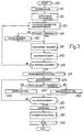
    1. A method of locating an optical code applied to an object (7), characterized by comprising:
      an image acquisition step (110) wherein at least one image (I) of an object (7) bearing said code (BC) is acquired;
      a first processing step (120) wherein the acquired image (I) is divided into a number of elementary images (If), each comprising a predetermined number (N) of pixels, and each pixel being assigned a pixel brightness value (A, B, C, D);
      a second processing step wherein a brightness gradient vector (G) is calculated for each of said elementary images (If);
      a first comparing step (140) wherein, from said calculated gradient vectors (G), the vectors of a magnitude above at least one threshold value (Glim) and representing rapid variations in brightness are selected;
      a transforming step wherein the previously selected gradient vectors are transformed to determine a given path and a given direction, which path and which direction are assigned to all the gradient vectors;
      a tiling step (180) wherein said acquired image (I) is divided into a number of subimages (Ip), each comprising a number of elementary images (If);
      a composing step (220) wherein the previously transformed gradient vectors of a selected subimage (Ip) are added to calculate a total gradient vector (Gs);
      a second comparing step (230) wherein said total gradient vector (Gs) of each of said subimages (Ip) is compared with reference values to select (240) significant subimages containing a sufficient number of gradient vectors having substantially the same path; the significant subimages being assigned a first binary logic value ("1"); said second comparing step (230) also determining (250) nonsignificant subimages containing a limited number of gradient vectors having substantially the same path; the nonsignificant subimages being assigned a second binary logic value ("0");
         said method generating at least one final binary image (Ir) representing said acquired image (I) divided into said subimages (Ip), each having a respective binary logic value.
    2. A method as claimed in Claim 1, wherein said optical code is a bar code (BC), characterized in that the angle (α) formed by said gradient vector with a cartesian reference system is doubled during said transforming step.
    3. A method as claimed in Claim 1, characterized in that, during said transforming step, the angle (α) formed by said gradient vector with a cartesian reference system is multiplied by a factor equal to the number of sides of the geometric figure forming the unit element of the optical code.
    4. A method as claimed in Claim 3, wherein said optical code is a two-dimensional code having a unit element defined by four sides; characterized in that, during said transforming step, the angle (α) formed by said gradient vector with a cartesian reference system is multiplied by a factor of four.
    5. A method as claimed in Claim 3, wherein said optical code is a two-dimensional code having a unit element defined by six sides; characterized in that, during said transforming step, the angle (α) formed by said gradient vector with a cartesian reference system is multiplied by a factor of six.
    6. A method as claimed in any one of the foregoing Claims, characterized in that said transforming step (190) is followed by a quantizing step (200) wherein the calculated gradient vectors are approximated to the closest vector in a series of reference vectors.
    7. A method as claimed in Claim 6, characterized in that said reference vectors comprise four first unit vectors perpendicular to one another, and four second vectors perpendicular to one another and forming an angle of 45° with the first vectors.
    8. A method as claimed in any one of the foregoing Claims, characterized by comprising a further processing step (270) of said final binary image (Ir), wherein the binary value of each subimage is replaced by the binary value of the majority of the adjacent subimages.
    9. A method as claimed in any one of the foregoing Claims, characterized by comprising a pattern recognition step (280), wherein said final image (Ir) is examined to determine the subimage groups of said first binary value;
         said pattern recognition step (280) distinguishing, from the recognized subimage groups, typical subimage groups having said first binary value and most likely corresponding to significant portions of said acquired image corresponding to digital code images.
    10. A method as claimed in Claim 9, characterized in that said pattern recognition step (280) is followed by a reading step, wherein the code contained in said significant portions is read automatically.
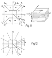
    11. A method as claimed in any one of the foregoing Claims, characterized in that, in said second comparing step, said total gradient vector (Gs) is compared with threshold values and with a number of reference paths;
         the cartesian space in which said total gradient vector (Gs) is representable being divided into a central portion defined by threshold values, and into a number of radial portions outside the central portion and corresponding to respective paths of the total gradient vector; each radial portion corresponding to at least one respective binary plane comprising a number of subimages, the binary value of which is determined by comparing said total gradient vector with said threshold values.
    12. A method as claimed in any one of the foregoing Claims, characterized in that said composing step (220) is followed by a step wherein each total gradient vector (Gs) generated for a respective subimage (Ip) is replaced by the mean total gradient vector of all the subimages (Ip) within a predetermined neighbourhood of said subimage (Ip), to generate a composite total gradient vector;
         the composite total gradient vector being compared with threshold values in said second comparing step (230) to determine significant subimage groups.
    13. A device for locating an optical code applied to an object (7), characterized by comprising:
      image acquisition means (22, 110) for acquiring at least one image (I) of an object (7) bearing said code (BC);
      first processing means (120) wherein the acquired image (I) is divided into a number of elementary images (If), each comprising a predetermined number (N) of pixels; and each pixel being assigned a pixel brightness value (a, B, C, D);
      second processing means wherein a brightness gradient vector (G) is calculated for each of said elementary images (If);
      first comparing means (140) wherein, from said calculated gradient vectors (G), the vectors of a magnitude above at least one threshold value (Glim) and representing rapid variations in brightness are selected;
      transforming means wherein the previously selected gradient vectors are transformed to determine a given path and a given direction, which path and which direction are assigned to all the calculated gradient vectors;
      tiling means (180) wherein said acquired image (I) is divided into a number of subimages (Ip), each comprising a number of elementary images (If);
      composing means (220) wherein the previously transformed gradient vectors of a selected subimage (Ip) are added to calculate a total gradient vector (Gs);
      second comparing means (230) wherein said total gradient vector (Gs) of each of said subimages (Ip) is compared with reference values to select (240) significant subimages containing a sufficient number of gradient vectors having substantially the same path; the significant subimages being assigned a first binary logic value ("1"); said second comparing means (230) also determining (250) nonsignificant subimages containing a limited number of gradient vectors having substantially the same path; the nonsignificant subimages being assigned a second binary logic value ("0");
         said device generating at least one final binary image (Ir) representing said acquired image (I) divided into said subimages (Ip), each having a respective binary logic value.
    14. A device as claimed in Claim 13, wherein said optical code is a bar code (BC), characterized in that said transforming means double the angle (α) formed by said gradient vector with a reference system.
    15. A device as claimed in Claim 13, characterized in that said transforming means multiply the angle (α) formed by said gradient vector with a cartesian reference system by a factor equal to the number of sides of the geometric figure forming the unit element of the optical code.
    16. A device as claimed in Claim 15, wherein said optical code is a two-dimensional code having a unit element defined by four sides, characterized in that said factor equals four.
    17. A device as claimed in Claim 15, wherein said optical code is a two-dimensional code having a unit element defined by six sides, characterized in that said factor equals six.
    EP96830661A 1996-12-30 1996-12-30 Method of locating an object-applied code Expired - Lifetime EP0851374B1 (en)

    Priority Applications (4)

    Application Number Priority Date Filing Date Title
    AT96830661T ATE249650T1 (en) 1996-12-30 1996-12-30 METHOD FOR LOCATING A CODE APPLIED TO AN OBJECT
    EP96830661A EP0851374B1 (en) 1996-12-30 1996-12-30 Method of locating an object-applied code
    DE69629930T DE69629930T2 (en) 1996-12-30 1996-12-30 Method for setting an optical code attached to an object
    US09/000,797 US6047893A (en) 1996-12-30 1997-12-30 Method of locating an object-applied optical code

    Applications Claiming Priority (1)

    Application Number Priority Date Filing Date Title
    EP96830661A EP0851374B1 (en) 1996-12-30 1996-12-30 Method of locating an object-applied code

    Publications (2)

    Publication Number Publication Date
    EP0851374A1 true EP0851374A1 (en) 1998-07-01
    EP0851374B1 EP0851374B1 (en) 2003-09-10

    Family

    ID=8226101

    Family Applications (1)

    Application Number Title Priority Date Filing Date
    EP96830661A Expired - Lifetime EP0851374B1 (en) 1996-12-30 1996-12-30 Method of locating an object-applied code

    Country Status (4)

    Country Link
    US (1) US6047893A (en)
    EP (1) EP0851374B1 (en)
    AT (1) ATE249650T1 (en)
    DE (1) DE69629930T2 (en)

    Cited By (2)

    * Cited by examiner, † Cited by third party
    Publication number Priority date Publication date Assignee Title
    US6775409B1 (en) 1998-10-23 2004-08-10 Data Logic S.P.A. Method for locating codes in bidimensional images
    US10825137B2 (en) 2019-01-15 2020-11-03 Datalogic IP Tech, S.r.l. Systems and methods for pre-localization of regions of interest for optical character recognition, and devices therefor

    Families Citing this family (26)

    * Cited by examiner, † Cited by third party
    Publication number Priority date Publication date Assignee Title
    EP0917080B1 (en) * 1997-11-17 2001-07-18 DATALOGIC S.p.A. Method of locating highly variable brightness or colour regions in an image
    DE19840455A1 (en) * 1998-09-04 2000-03-09 Sick Ag Method for operating a bar code reader
    US7137711B1 (en) 2000-03-21 2006-11-21 Leonard Reiffel Multi-user retro reflector data input
    ATE403908T1 (en) * 2000-05-03 2008-08-15 Leonard Reiffel DUAL MODE DATA IMAGING PRODUCT
    DE60134759D1 (en) * 2000-08-18 2008-08-21 Leonard Reiffel NOTE PICTURE DATA PRODUCT
    US7034803B1 (en) 2000-08-18 2006-04-25 Leonard Reiffel Cursor display privacy product
    WO2002049340A1 (en) * 2000-12-15 2002-06-20 Leonard Reiffel Multi-imager multi-source multi-use coded data source data input product
    US7184075B2 (en) * 2000-12-15 2007-02-27 Leonard Reiffel Imaged coded data source tracking product
    US6945460B2 (en) * 2000-12-15 2005-09-20 Leonard Reiffel Imaged coded data source transducer product
    EP1390909A4 (en) * 2001-04-19 2004-12-29 Leonard Reiffel Combined imaging coded data source data acquisition
    US6729544B2 (en) * 2001-05-02 2004-05-04 International Business Machines Corporation Fast barcode search
    GB2392286B (en) * 2002-08-19 2004-07-07 Chunghwa Telecom Co Ltd Personal identification system based on the reading of multiple one-dimensional barcodes scanned from scanned from PDA/cell phone screen
    SE0301143D0 (en) * 2003-04-17 2003-04-17 C Technologies Ab Method and device for loading data
    US20060291797A1 (en) * 2003-05-27 2006-12-28 Leonard Reiffel Multi-imager multi-source multi-use coded data source data input product
    US7376894B2 (en) * 2004-11-18 2008-05-20 Microsoft Corporation Vector path merging into gradient elements
    WO2006078359A1 (en) * 2004-12-03 2006-07-27 Symbol Technologies, Inc. Bar code scanner decoding
    US7337970B2 (en) * 2004-12-03 2008-03-04 Symbol Technologies, Inc. Barcode scanner decoding
    US20100084470A1 (en) * 2008-10-03 2010-04-08 Microsoft Corporation Two-dimensional barcode localization for camera based devices
    JP5651659B2 (en) * 2012-08-31 2015-01-14 株式会社東芝 Object detection system and program
    ITUB20154043A1 (en) 2015-09-30 2017-03-30 Datalogic IP Tech Srl System and method of reading encoded information
    JP6837880B2 (en) * 2017-03-15 2021-03-03 株式会社東芝 Image processing equipment, image processing systems, image processing methods, and programs
    US10262436B2 (en) * 2017-08-25 2019-04-16 Datalogic Ip Tech S.R.L. System for multiple decode of captured images
    US10346660B2 (en) * 2017-08-25 2019-07-09 Datalogic I.P. Tech S.R.L. Coded image capture and decoding system
    GB2575333B (en) * 2018-12-21 2020-09-09 Imagination Tech Ltd Double-angle gradients
    US10817693B1 (en) 2019-07-10 2020-10-27 Datalogic Ip Tech S.R.L. System for decode of two-dimensional indicia
    US11003881B2 (en) 2019-09-11 2021-05-11 Datalogic Ip Tech S.R.L. System for multiple decode of captured images

    Citations (4)

    * Cited by examiner, † Cited by third party
    Publication number Priority date Publication date Assignee Title
    US5268580A (en) * 1992-09-02 1993-12-07 Ncr Corporation Bar code enhancement system and method for vision scanners
    US5296690A (en) * 1991-03-28 1994-03-22 Omniplanar, Inc. System for locating and determining the orientation of bar codes in a two-dimensional image
    US5304787A (en) * 1993-06-01 1994-04-19 Metamedia Corporation Locating 2-D bar codes
    US5504319A (en) * 1994-02-09 1996-04-02 Symbol Technologies, Inc. Method and system for bar code acquisition

    Family Cites Families (1)

    * Cited by examiner, † Cited by third party
    Publication number Priority date Publication date Assignee Title
    US4874936A (en) * 1988-04-08 1989-10-17 United Parcel Service Of America, Inc. Hexagonal, information encoding article, process and system

    Patent Citations (4)

    * Cited by examiner, † Cited by third party
    Publication number Priority date Publication date Assignee Title
    US5296690A (en) * 1991-03-28 1994-03-22 Omniplanar, Inc. System for locating and determining the orientation of bar codes in a two-dimensional image
    US5268580A (en) * 1992-09-02 1993-12-07 Ncr Corporation Bar code enhancement system and method for vision scanners
    US5304787A (en) * 1993-06-01 1994-04-19 Metamedia Corporation Locating 2-D bar codes
    US5504319A (en) * 1994-02-09 1996-04-02 Symbol Technologies, Inc. Method and system for bar code acquisition

    Cited By (2)

    * Cited by examiner, † Cited by third party
    Publication number Priority date Publication date Assignee Title
    US6775409B1 (en) 1998-10-23 2004-08-10 Data Logic S.P.A. Method for locating codes in bidimensional images
    US10825137B2 (en) 2019-01-15 2020-11-03 Datalogic IP Tech, S.r.l. Systems and methods for pre-localization of regions of interest for optical character recognition, and devices therefor

    Also Published As

    Publication number Publication date
    US6047893A (en) 2000-04-11
    ATE249650T1 (en) 2003-09-15
    EP0851374B1 (en) 2003-09-10
    DE69629930D1 (en) 2003-10-16
    DE69629930T2 (en) 2004-07-22

    Similar Documents

    Publication Publication Date Title
    EP0851374B1 (en) Method of locating an object-applied code
    US4969202A (en) Image recognition edge detection method and system
    US6377698B1 (en) Method of locating highly variable brightness or color regions in an image
    JP2832646B2 (en) Method and apparatus for determining a fine azimuth of a barcode symbol in a two-dimensional CDD image
    US5081689A (en) Apparatus and method for extracting edges and lines
    JP3910447B2 (en) Multi-resolution label locator
    US5668898A (en) Device for detecting the inclination of image
    JP3251918B2 (en) Binarization method in optical character recognition system
    JPH0413748B2 (en)
    KR20060100376A (en) Method and image processing device for analyzing an object contour image, method and image processing device for detecting an object, industrial vision apparatus, smart camera, image display, security system, and computer program product
    JPH04287290A (en) Hough transformation picture processor
    JPH0799581A (en) Picture processing device
    JP7062722B2 (en) Specifying the module size of the optical cord
    US5438636A (en) Apparatus for simultaneously convolving multiple digital binary images using a single convolver with a binary mask to determine pixel densities
    US4831658A (en) Binary signal producing apparatus for optical character recognition
    CA2230197C (en) Strand orientation sensing
    CN110717890A (en) Butt joint ring identification method and medium
    JP2009032202A (en) Two-dimensional code reader and method therefor
    JP2000329538A (en) Surface-inspecting apparatus
    EP0447541B1 (en) Image data processor system and method
    CA2208788C (en) Method and apparatus for simultaneously convolving multiple digital binary images using a single convolver with a binary mask to determine pixel densities
    JPH05113315A (en) Detecting method for center position of circular image data
    JPH09330417A (en) Shape measuring unit
    Mehenni et al. A highly parallel system for the visual inspection of printed containers.
    JPH0199174A (en) Shape recognizing device

    Legal Events

    Date Code Title Description
    PUAI Public reference made under article 153(3) epc to a published international application that has entered the european phase

    Free format text: ORIGINAL CODE: 0009012

    AK Designated contracting states

    Kind code of ref document: A1

    Designated state(s): AT BE CH DE DK ES FI FR GB GR IE IT LI

    AX Request for extension of the european patent

    Free format text: AL;LT;LV;RO;SI

    AKX Designation fees paid
    RBV Designated contracting states (corrected)
    17P Request for examination filed

    Effective date: 19981229

    RBV Designated contracting states (corrected)

    Designated state(s): AT BE CH DE DK ES FR GB IT LI NL PT SE

    RAP1 Party data changed (applicant data changed or rights of an application transferred)

    Owner name: DATALOGIC S.P.A.

    GRAH Despatch of communication of intention to grant a patent

    Free format text: ORIGINAL CODE: EPIDOS IGRA

    GRAS Grant fee paid

    Free format text: ORIGINAL CODE: EPIDOSNIGR3

    GRAA (expected) grant

    Free format text: ORIGINAL CODE: 0009210

    AK Designated contracting states

    Kind code of ref document: B1

    Designated state(s): AT BE CH DE DK ES FR GB IT LI NL PT SE

    PG25 Lapsed in a contracting state [announced via postgrant information from national office to epo]

    Ref country code: NL

    Free format text: LAPSE BECAUSE OF FAILURE TO SUBMIT A TRANSLATION OF THE DESCRIPTION OR TO PAY THE FEE WITHIN THE PRESCRIBED TIME-LIMIT

    Effective date: 20030910

    Ref country code: LI

    Free format text: LAPSE BECAUSE OF FAILURE TO SUBMIT A TRANSLATION OF THE DESCRIPTION OR TO PAY THE FEE WITHIN THE PRESCRIBED TIME-LIMIT

    Effective date: 20030910

    Ref country code: CH

    Free format text: LAPSE BECAUSE OF FAILURE TO SUBMIT A TRANSLATION OF THE DESCRIPTION OR TO PAY THE FEE WITHIN THE PRESCRIBED TIME-LIMIT

    Effective date: 20030910

    Ref country code: BE

    Free format text: LAPSE BECAUSE OF FAILURE TO SUBMIT A TRANSLATION OF THE DESCRIPTION OR TO PAY THE FEE WITHIN THE PRESCRIBED TIME-LIMIT

    Effective date: 20030910

    Ref country code: AT

    Free format text: LAPSE BECAUSE OF FAILURE TO SUBMIT A TRANSLATION OF THE DESCRIPTION OR TO PAY THE FEE WITHIN THE PRESCRIBED TIME-LIMIT

    Effective date: 20030910

    REG Reference to a national code

    Ref country code: GB

    Ref legal event code: FG4D

    REG Reference to a national code

    Ref country code: CH

    Ref legal event code: EP

    REF Corresponds to:

    Ref document number: 69629930

    Country of ref document: DE

    Date of ref document: 20031016

    Kind code of ref document: P

    PG25 Lapsed in a contracting state [announced via postgrant information from national office to epo]

    Ref country code: SE

    Free format text: LAPSE BECAUSE OF FAILURE TO SUBMIT A TRANSLATION OF THE DESCRIPTION OR TO PAY THE FEE WITHIN THE PRESCRIBED TIME-LIMIT

    Effective date: 20031210

    Ref country code: DK

    Free format text: LAPSE BECAUSE OF FAILURE TO SUBMIT A TRANSLATION OF THE DESCRIPTION OR TO PAY THE FEE WITHIN THE PRESCRIBED TIME-LIMIT

    Effective date: 20031210

    PG25 Lapsed in a contracting state [announced via postgrant information from national office to epo]

    Ref country code: PT

    Free format text: LAPSE BECAUSE OF FAILURE TO SUBMIT A TRANSLATION OF THE DESCRIPTION OR TO PAY THE FEE WITHIN THE PRESCRIBED TIME-LIMIT

    Effective date: 20031215

    PGFP Annual fee paid to national office [announced via postgrant information from national office to epo]

    Ref country code: FR

    Payment date: 20031218

    Year of fee payment: 8

    PG25 Lapsed in a contracting state [announced via postgrant information from national office to epo]

    Ref country code: ES

    Free format text: LAPSE BECAUSE OF FAILURE TO SUBMIT A TRANSLATION OF THE DESCRIPTION OR TO PAY THE FEE WITHIN THE PRESCRIBED TIME-LIMIT

    Effective date: 20031221

    NLV1 Nl: lapsed or annulled due to failure to fulfill the requirements of art. 29p and 29m of the patents act
    REG Reference to a national code

    Ref country code: CH

    Ref legal event code: PL

    ET Fr: translation filed
    PLBE No opposition filed within time limit

    Free format text: ORIGINAL CODE: 0009261

    STAA Information on the status of an ep patent application or granted ep patent

    Free format text: STATUS: NO OPPOSITION FILED WITHIN TIME LIMIT

    26N No opposition filed

    Effective date: 20040614

    PG25 Lapsed in a contracting state [announced via postgrant information from national office to epo]

    Ref country code: FR

    Free format text: LAPSE BECAUSE OF NON-PAYMENT OF DUE FEES

    Effective date: 20050831

    REG Reference to a national code

    Ref country code: FR

    Ref legal event code: ST

    PG25 Lapsed in a contracting state [announced via postgrant information from national office to epo]

    Ref country code: IT

    Free format text: LAPSE BECAUSE OF NON-PAYMENT OF DUE FEES

    Effective date: 20051230

    PGFP Annual fee paid to national office [announced via postgrant information from national office to epo]

    Ref country code: GB

    Payment date: 20151221

    Year of fee payment: 20

    Ref country code: DE

    Payment date: 20151211

    Year of fee payment: 20

    REG Reference to a national code

    Ref country code: DE

    Ref legal event code: R071

    Ref document number: 69629930

    Country of ref document: DE

    REG Reference to a national code

    Ref country code: GB

    Ref legal event code: PE20

    Expiry date: 20161229

    PG25 Lapsed in a contracting state [announced via postgrant information from national office to epo]

    Ref country code: GB

    Free format text: LAPSE BECAUSE OF EXPIRATION OF PROTECTION

    Effective date: 20161229