EP0851205A2 - Optical interferometer and signal synthesizer using the interferometer - Google Patents
Optical interferometer and signal synthesizer using the interferometer Download PDFInfo
- Publication number
- EP0851205A2 EP0851205A2 EP97122416A EP97122416A EP0851205A2 EP 0851205 A2 EP0851205 A2 EP 0851205A2 EP 97122416 A EP97122416 A EP 97122416A EP 97122416 A EP97122416 A EP 97122416A EP 0851205 A2 EP0851205 A2 EP 0851205A2
- Authority
- EP
- European Patent Office
- Prior art keywords
- optical
- interferometer
- path
- paths
- light
- Prior art date
- Legal status (The legal status is an assumption and is not a legal conclusion. Google has not performed a legal analysis and makes no representation as to the accuracy of the status listed.)
- Granted
Links
- 230000003287 optical effect Effects 0.000 title claims abstract description 222
- 238000001228 spectrum Methods 0.000 claims description 49
- 239000004065 semiconductor Substances 0.000 claims description 22
- 239000000758 substrate Substances 0.000 claims description 22
- 238000000034 method Methods 0.000 claims description 8
- 230000004044 response Effects 0.000 claims description 3
- 230000003595 spectral effect Effects 0.000 claims description 3
- 230000008054 signal transmission Effects 0.000 claims description 2
- 230000003019 stabilising effect Effects 0.000 claims 3
- 230000008878 coupling Effects 0.000 claims 1
- 238000010168 coupling process Methods 0.000 claims 1
- 238000005859 coupling reaction Methods 0.000 claims 1
- 238000002789 length control Methods 0.000 claims 1
- 230000000295 complement effect Effects 0.000 abstract description 3
- 238000012544 monitoring process Methods 0.000 abstract description 2
- 238000010586 diagram Methods 0.000 description 15
- 238000004891 communication Methods 0.000 description 6
- 238000003786 synthesis reaction Methods 0.000 description 4
- 230000005540 biological transmission Effects 0.000 description 3
- 230000015572 biosynthetic process Effects 0.000 description 3
- 230000004048 modification Effects 0.000 description 3
- 238000012986 modification Methods 0.000 description 3
- 238000012546 transfer Methods 0.000 description 3
- XKRFYHLGVUSROY-UHFFFAOYSA-N Argon Chemical compound [Ar] XKRFYHLGVUSROY-UHFFFAOYSA-N 0.000 description 2
- 230000001419 dependent effect Effects 0.000 description 2
- RTAQQCXQSZGOHL-UHFFFAOYSA-N Titanium Chemical compound [Ti] RTAQQCXQSZGOHL-UHFFFAOYSA-N 0.000 description 1
- 238000010521 absorption reaction Methods 0.000 description 1
- 229910052786 argon Inorganic materials 0.000 description 1
- 230000008859 change Effects 0.000 description 1
- 239000013078 crystal Substances 0.000 description 1
- 230000000694 effects Effects 0.000 description 1
- 230000012447 hatching Effects 0.000 description 1
- 239000004973 liquid crystal related substance Substances 0.000 description 1
- 238000004519 manufacturing process Methods 0.000 description 1
- 239000013307 optical fiber Substances 0.000 description 1
- 230000005693 optoelectronics Effects 0.000 description 1
- 229920006254 polymer film Polymers 0.000 description 1
- 230000008569 process Effects 0.000 description 1
- 230000035945 sensitivity Effects 0.000 description 1
- 238000000926 separation method Methods 0.000 description 1
- 230000006641 stabilisation Effects 0.000 description 1
- 238000011105 stabilization Methods 0.000 description 1
- 230000001360 synchronised effect Effects 0.000 description 1
- 230000002194 synthesizing effect Effects 0.000 description 1
- 229910052719 titanium Inorganic materials 0.000 description 1
- 239000010936 titanium Substances 0.000 description 1
Images


Classifications
-
- H—ELECTRICITY
- H04—ELECTRIC COMMUNICATION TECHNIQUE
- H04B—TRANSMISSION
- H04B10/00—Transmission systems employing electromagnetic waves other than radio-waves, e.g. infrared, visible or ultraviolet light, or employing corpuscular radiation, e.g. quantum communication
- H04B10/50—Transmitters
-
- G—PHYSICS
- G01—MEASURING; TESTING
- G01J—MEASUREMENT OF INTENSITY, VELOCITY, SPECTRAL CONTENT, POLARISATION, PHASE OR PULSE CHARACTERISTICS OF INFRARED, VISIBLE OR ULTRAVIOLET LIGHT; COLORIMETRY; RADIATION PYROMETRY
- G01J9/00—Measuring optical phase difference; Determining degree of coherence; Measuring optical wavelength
- G01J9/02—Measuring optical phase difference; Determining degree of coherence; Measuring optical wavelength by interferometric methods
Definitions
- This invention relates to an optical interferometer and a signal synthesizer, and particularly to an optical interferometer applied to an optoelectronic device for performing signal processes for operations or communications, which are modeledng optical pulses and a signal synthesizer using the optical interferometer.
- On/off switching of output optical pulses using the difference in phase between two optical paths of a Mach-Zehnder interferometer is a well-known technique.
- a long pulse of sub-nanoseconds or so has heretofore been used, the spectrum of the pulse is very narrow.
- the conventional Mach-Zehnder interferometer controls the intensities of the output optical pulses but encounters difficulties in controlling their spectra.
- the prior art has a problem in that although it performs intensity modulation on the output optical pulses with respect to relatively long pulse of sub-nanoseconds or so, the control of the spectra of the output optical pulses or the effective synthesis of signals by decompositing the spectrum and controlling each spectral component has not yet been taken into consideration.
- An object of the present invention is to provide an optical interferometer capable of allowing control of spectra, control of output optical pulses by utilizing a controlled stable interferometer and a femtosecond pulse having a wide bandwidth in combination, and a signal synthesizer using the optical interferometer, and a signal transmission method.
- an optical path control means for stably controlling an optical path difference between divided optical pulses is provided in the present invention.
- Stable output optical pulses are obtained by holding the optical path difference in a predetermined relationship and respective spectra of the resultant output optical pulses are controlled by modulating signals, thereby making it possible to synthesize signals for optical communications. It is thus possible to perform multiplexed optical communications.
- the commonly used interferometer cannot obtain output pulses stabilized in the phase domain due to fluctuations of the optical path difference developed within the interferometer.
- a monochrometer is provided which monitors fluctuations of an optical path difference developed in the interferometer, based on one of two output optical pulses produced from the interferometer to thereby effect feedback on the optical path difference in the interferometer, thus providing stabilization in the phase domain.
- an interferometer which makes up of a semiconductor and strict temperature control is performed to stabilize the fluctuations in the phase domain. If further necessary, then feedback for adjusting the length of the optical path is effected on one optical path to compensate for the fluctuations of the optical path difference as well as for the temperature control.
- the two optical-path interferometer for example, the Mach-Zehnder interferometer is capable of controlling the optical path difference in a resolution of 1/20 or less of the central wavelength of the input optical pulse, i.e., sub-femtoseconds if described by time.
- the spectrum of each pulse outputted from the interferometer with respect to the input femtosecond pulse can be stably controlled.
- Fig. 1A is a block diagram of one embodiment of a phase-locked interferometer according to the present invention.
- the present embodiment illustrates a phase-locked interferometer 50 which comprises a two optical-path interferometer 5 and a device for performing feedback to monitor fluctuations of an optical path difference developed in the interferometer and compensate for the fluctuations.
- the two optical-path interferometer 5 comprises two optical paths 7 and 7' formed by a beam splitter 4, mirrors 6 and a beam splitter 4.
- One optical path 7' is nothing but the configuration of a simple optical path.
- the mirror 6 is mounted to a piezo electrically actuated optical stage 1 which vibrates with a frequency of a few thousand hertz and with an amplitude of about 1/40 the wavelength of an input optical pulse.
- the piezo electrically actuated optical stage 1 is mounted to a piezo electrically actuated optical stage for compensation 2.
- the piezo-controlled optical stage 2 fine-adjusts the position of the mirror 6 according to a position control signal to be described later to thereby adjust or control its optical path length.
- a motor controlled optical stage 13 for rough-adjusting the optical path length is interposed in the optical path 7.
- a predetermined interference status in the initial state of the interferometer can be created under the control of the motor controlled optical stage 13.
- the optical stages 1, 2 and 13 for controlling the optical path length are provided within the optical path 7 in Fig. 1A. It is however needless to say that the optical stages 1 and 2 may be provided within the optical path 7 and the optical stage 13 may be provided within the optical path 7' and that the optical stages 1 and 2 can be in the optical paths 7' and 7', respectively.
- a femtosecond titanium sapphire laser pumped by an argon laser was used as an optical pulse source inputted to the two optical-path interferometer 5.
- the width of a pulse outputted from the laser is 10fs.
- the present laser pulse is allowed to pass through a ⁇ - B a B 2 O 4 (BBO) crystal to thereby generate second harmonics (whose wavelength ranges from 370nm to 410nm) (pulse width ranging from 12fs to 15fs).
- BBO B 2 O 4
- the piezo-controlled optical stage 1 is vibrated by an oscillator 12 and it is possible to obtain a component synchronized with the vibration of the optical intensity output of the photo-detector 9 from a lock-in amplifier 10.
- the lock-in amplifier 10 detects a variation in the optical path difference from a variation in the output of the photo-detector 9 and compensates for the detected variation, and outputs a compensation signal 11 to the optical stage 2 so as to hold the optical path difference constant.
- the present embodiment can offer high sensitivity to the change in the optical path difference.
- reference numeral 14 in Fig. 1A indicates one example of a portion for inputting a modulating signal.
- This portion corresponds to an addition circuit which adds a signal S to the output of the lock-in amplifier 10.
- the signal S is added to the output of the lock-in amplifier 10
- an error would be as if to have occurred in the optical path difference by its addition.
- the difference between the two optical paths 7 and 7' is reversed so that the output optical pulses of spectra ⁇ 2 and ⁇ 1 are obtained from the optical paths 7 and 7' respectively.
- the addition circuit results in one necessary when the interferometer is used as a signal synthesizer by controlling the optical path difference of the interferometer 5 shown as the embodiment. This will be described later.
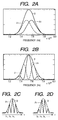
- Figs. 2A through 2D are respectively diagrams illustrating examples of spectra of the optical pulses inputted to the phase-locked interferometer 50 shown in Fig. 1A and spectra of output optical pulses.
- a thick solid line 3 indicates the spectrum of an incident pulse.
- a thick sold line 3 indicates the spectrum of an incident pulse.
- the number of peaks of the frequency in the output spectrum can be arbitrarily set by setting n on an arbitrary basis.
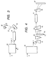
- Fig. 3 is a block diagram showing a signal synthesizer for controlling pulses ⁇ 1 and ⁇ 2 outputted from a phase-locked interferometer 50 according to 1/0 of a modulating signal S and an example in which communications are made by the signal synthesizer.
- the phase-locked interferometer can be constructed as the signal synthesizer by controlling the optical path difference of the interferometer 5.
- An incident pulse 3 is supplied to the phase-locked interferometer 50 and a signal corresponding to a signal to be transmitted is applied to the phase-locked interferometer 50.
- the spectrum of the output optical pulse produced from the interferometer 50 according to the signal S results in ⁇ 1 or ⁇ 2 . Namely, it is possible to generate a signal corresponding to an output optical pulse of a spectrum ⁇ 1 or ⁇ 2 corresponding to 0 or 1 of the signal S. In this case, either one of the optical paths 7 and 7' may be used.
- This signal pulse is allowed to pass through an optical transmission or transfer medium 19 so as to be transmitted to signal receiving points.
- Signals at receiving points are detected as follows: Optical pulses 21 diffracted to different positions according to the wavelength by a diffraction grating 20 are detected by their corresponding photo-detectors 22 to thereby make it possible to determine the signal of 0 or 1.
- the atmosphere can be used as the optical transfer medium 19, a wave-guiding channel or waveguide, or optical fiber may be used.
- an output spectrum obtained from an optical path 7 or 7' of a phase-locked interferometer 50 is set so as to have a number of central frequencies as shown in Figs. 2C and 2D and it is controlled so as to be held constant.
- the output optical pulse obtained from either one of the optical paths 7 and 7' is spatially separated into parallel beams by prisms 61 and 62.
- an absorption light modulator 63 is placed on optical paths of the parallel beams.
- the light modulator 63 is supplied with a signal S to control the turning on and off of frequencies corresponding to respective locations or places for the light modulator 63.
- a signal S to control the turning on and off of frequencies corresponding to respective locations or places for the light modulator 63.
- the parallel beams are gathered again by prisms 64 and 65, they are allowed to pass through an optical transfer medium 19.
- lenses may be used in place of the prisms 62 and 64.
- the transmitted signal is detected by a position-dependent one-dimensional photo-detector 67. Namely, position information about the turning on and off of the optical pulses at the optical modulator 63 can be transmitted to the photo-detector 67.
- the present embodiment has described the case in which either one of the optical paths 7 and 7' is used. However, if similar devices are provided for the output optical pulses obtained from the respective optical paths, then the signal can be transmitted twice. Since the signal can be separated on the receiving side every wavelengths in this case, the transmission itself may be integrated into one transmission path. Namely, according to the present embodiment, the electric signal for controlling the light modulator 63 is converted into the on/off of light intensity to thereby make it possible to transmit a signal in wavelength multiple form.
- a phase-locked interferometer which makes use of both the aforementioned optical paths 7 and 7' and mounts them on a semiconductor substrate.
- Fig. 5 is a block diagram showing a basic configuration of the phase-locked interferometer and draws even signal waveforms at respective input/output positions side by side together with the configuration of the phase-locked interferometer.
- Reference numeral 100 indicates a Mach-Zehnder interferometer of two optical paths, into which an optical pulse 3 having the continuos spectrum and time characteristics shown in Figs. 1B and 1C is launched. The output of the interferometer 100 is divided into two whose respective spectra result in discrete spectra like ⁇ 1 and ⁇ 2 .
- Reference numerals 200 and 300 indicate multichannel modulators into which optical pulses having spectra ⁇ 1 and ⁇ 2 are launched, respectively.
- Each channel of the multichannel modulator 200 and 300 corresponds to the modulation channel of a specific frequency.
- the multichannel modulators 200 and 300 are respectively supplied with modulating signals S 1 and S 2 and modulate the input optical pulses in response to these signals.
- the modulated optical pulses result in optical signals having spectra designated at numerals 201 and 301 respectively.
- Reference numeral 400 indicates an optical coupler which makes use of a half mirror, for example.
- the coupler 400 re-synthesizes the optical signals having the spectra 201 and 301 and produces the final output 401 therefrom.
- the optical spectrum of the final output 401 lacks partly ,as shown in the drawing, in association with the modulating signals S 1 and S 2 .
- Output pulse waveform 402 indicating time characteristic greatly varies from the original input pulse waveform 3.
- An arbitrary pulse waveform is generated according to the modulating signals inputted to the multichannel modulators 200 and 300.
- the final output 401 results from the synthesis of the optical pulses having the spectra 201 and 301. Either of the two outputs from the optical coupler 400 may be used.
- Figs. 6A and 6B show a specific embodiment mounted on a semiconductor substrate.
- the present embodiment shows a signal synthesizer implemented by optical transparent triple layers provided on the semiconductor substrate.
- Reference numeral 2000 indicates a semiconductor substrate.
- Transparent triple layers 1003, 1002 and 1001 are stacked on the semiconductor substrate 2000. Refractive indexes of these triple layers are respectively defined as n 3 , n 2 and n 1 for the layer 1003 on the substrate side, the layer 1002 formed as the intermediate layer and the layer 1001 formed as the outermost layer where n 1 ⁇ n 2 and n 3 ⁇ n 2 are satisfied.
- Light to be introduced from the outside is focused into the intermediate layer 1002 and allowed to propagate with the light trapped in this layer.
- the triple layers used herein can be formed as a polymer film, for example, and in addition, it may be formed by a semiconductor layer.
- An example, in which an optical element is constructed of such triple layers, has been introduced in Fig. 9 entitled Optical Micromachine in OYOBUTURI (The Japane Society of Applied Physics), Vol. 66, No. 1, pp. 9 - 14.
- Reference numeral 3000 indicates a constant temperature device.
- the semiconductor substrate 2000 is placed on the constant temperature device 3000. Namely, the signal synthesizer mounted on the upper surface of the semiconductor substrate 2000 is maintained at a constant temperature in the present embodiment.
- the incident light or optical pulse having the spectrum shown in Fig. 1B is introduced into a waveguide 101 formed by the transparent triple layers 1001, 1002 and 1003.
- the part except waveguide structure has no triple layers.
- the incident light is introduced into an optical path constituting the interferometer 100 through the waveguide 101. Since the other waveguide 102 contacts the waveguide 101 so as to form a separation path in the interferometer 100, the incident light is divided into two optical-paths corresponding to the waveguides 101 and 102. These two optical-paths are brought into contact with each other again at positions where their optical path lengths differ from each other. As a result, interference occurs in the above-described incident light and hence waveforms of spectra ⁇ 1 and ⁇ 2 shown in Fig.
- the peak-to-peak frequency-difference of each waveform can be determined depending on the adjustment of each optical path length as described above. If further required, then a refractive index controller designated at numeral 110 is inserted into the optical path 101.
- the refractive index controller 110 can fine-adjust equivalently the substantial length of the optical path 101.
- the refractive index controller 110 is controlled by the voltage applied to each electrode provided at an upper portion of the optical path 101 to thereby control the refractive index. If required to stable the interferometer 100 in an analogy of Fig.1A, then an optical path 106 is used as a monitor, corresponding to the optical path 7'.
- the compensation signal 11, in this case, is acted to the refractive index controller 110 or the temperature controller.
- the light emitted from the optical path 101 and the light emitted from the optical path 102 are introduced into the multichannel modulators 200 and 300, respectively.
- regions indicated by dashed lines in the drawing are all built of triply piled-up layers.
- the multichannel modulators 200 and 300 are substantially identical in configuration to each other.
- the light or optical pulses launched from the optical paths 101 and 102 to the multichannel modulators 200 and 300 are set to parallel light beams by cut-away portions 210 and 310 having plano-concave shapes acting plano-convex lenses, respectively.
- the parallel light beams transmitted through the cut-away portions 210 and 310 are respectively introduced to cut-away portions 211 and 311 serving as diffraction gratings.
- the light or optical pulses separated into every frequency by the diffraction gratings 211 and 311 are focused on the spatial light modulators 231 and 331 every frequency through cut-away portions 221 an 321 acting plano-convex lenses.
- the spatial light modulators 231 and 331 allow the light or optical pulses subjected to optical modulation every frequency to pass therethrough because voltages for varying absorptance or refractive index are respectively applied to focusing positions associated with each frequency.
- the optical pulses transmitted through the spatial light modulators 231 and 331 are respectively introduced to cut-away portions 251 and 351 used to serve as diffraction gratings through cut-away portions 241 and 341 functioning as plano-convex lenses, where they are restored to the parallel light beams.
- the optical pulses restored to the parallel light beams are focused on their corresponding optical paths 103 and 104 through cut-away portions 261 and 361 acting plano-convex lenses.
- the optical pulses introduced into the optical paths 103 and 104 are coupled by the optical coupler 400 so that a signal waveform like the spectrum 401 shown in Fig. 5 is obtained.
- Figs. 7A and 7B are respectively cross-sectional views of the portions of the spatial light modulators 231 and 331 as viewed at positions taken along lines A - A in Fig. 6A.
- Reference numeral 2000 indicates a semiconductor substrate.
- Reference numerals 1003, 1002 and 1001 respectively indicate transparent layers stacked in three layers. Their refractive indexes are defined as n 3 , n 2 and n 1 (where n 1 ⁇ n 2 and n 3 ⁇ n 2 ).
- Reference numerals 85 respectively indicate electrodes which are provided on the transparent layer 1001 corresponding to the uppermost layer, where the electrode 85 and the substrate 2000 are electrically insulated.
- the positions of the electrodes, which are necessary for modulation, are represented as shown in Fig. 7A.
- the positions of the electrodes, which are necessary for modulation are represented as shown in Fig. 7B.
- different hatchings are provided in alternate order to clearly express the frequencies of the light transmitted through the intermediate transparent layer 1002. If the voltages applied (applied between the electrodes 85 and the semiconductor substrate 2000) to the electrodes 85 of the spatial light modulators 231 and 331 are controlled according to the modulating signals S 1 and S 2 , then arbitrary modulation can be done.
- the all transparent layers can be cut out in plano-concave shapes form to form the plano-convex lenses and their stepwise cutting can form the diffraction gratings. Therefore, the whole can be configured on the semiconductor substrate.
- the temperature control of the semiconductor substrate with high accuracy allows the implementation of a controlled stable interferometer.
- the control system for monitoring the fluctuations of the optical path difference of the interferometer according to the output optical pulse and thereby performing feedback on the optical path difference in the interferometer
- feedback compensating the fluctuations of the optical path difference and controlling the voltage applied to the refractive index controller 110 shown in Fig. 6A, can be also made as well as the strict temperature-control of the semiconductor substrate.
- a spectroscopic function comprised of the cut-away portions 210 and 310 serving as the plano-convex lenses, the cut-away portions 211 and 311 serving as the diffraction gratings and the cut-away portions 221 and 321 serving as the plano-convex lenses employed in the embodiment shown in Fig. 6A, can be also performed using a waveguide grating shown in Fig. 8.
- the waveguide grating is disclosed in Fig. 2 of the paper "Multifrequency Laser for Dense WDM Applications" introduced in the European Conference on Integrated Optics'97 subsequent to the filing of the present application. Light is incident or inputted from the left end in the drawing and is transmitted successively through a free space region, a waveguide, and another free space region.
- a light-gathering function comprised of the cut-away portions 241 and 341 serving as the plano-convex lenses, the cut-away portions 251 and 351 serving as the diffraction gratings, and the cut-away portions 261 and 361 serving as the plano-convex lenses, can be achieved in the same manner as described above.
- Fig. 9 is a diagram showing an embodiment of another configuration of the two optical-path interferometer.
- the present embodiment is different from the embodiment of the interferometer 100 shown in Fig. 6A, because the length of two optical-paths are substantially formed equally, and the refractive index of one of those two optical-paths, is changed so that the optical paths are equivalently different in length from each other.
- reference numerals 101 and 102 respectively indicate optical paths similar to those illustrated in the embodiment of Fig. 6A.
- Reference numeral 105 indicates an electrode.
- the refractive index can be controlled by controlling the voltage (applied between the electrode 105 and the semiconductor substrate 2000) applied to the electrode 105.
- the optical path lengths can be equivalently rendered different from each other even if the optical paths are structurally identical in length to each other.
- the present embodiment has the merit of being capable of accommodating fluctuations in manufacture by control.
- a stable interferometer can be obtained in a resolution of 1/20 or less of the central wavelength of an input optical pulse. Further, the interferometer of the present invention can control the spectra of output pulses obtained when femtosecond pulses are inputted.
- the output of the interferometer can be brought to discrete spectrums, light can be adjusted so as not to exist in a light-unmodulable region on a spatial light modulator. If both optical paths of the interferometer are used for signal synthesis, then optical synthesizing can be totally effected on a continuous spectrum over the entire range of the spectrum.
Landscapes
- Physics & Mathematics (AREA)
- Spectroscopy & Molecular Physics (AREA)
- General Physics & Mathematics (AREA)
- Electromagnetism (AREA)
- Engineering & Computer Science (AREA)
- Computer Networks & Wireless Communication (AREA)
- Signal Processing (AREA)
- Optical Modulation, Optical Deflection, Nonlinear Optics, Optical Demodulation, Optical Logic Elements (AREA)
- Spectrometry And Color Measurement (AREA)
Abstract
Description
Claims (18)
- An optical interferometer comprising:a two optical-path interferometer having means for controlling the length of one optical path,means for detecting fluctuations in the difference between optical path lengths of said interferometer, andmeans for feeding a signal corresponding to the fluctuations back to said control means so as to compensate the detected fluctuations.
- The interferometer of claim 1, wherein the optical pulse applied to said two optical-path interferometer is a femtosecond pulse.
- The interferometer of claim 1, wherein the phase of the difference between the optical path lengths is arbitrarily set.
- An optical interferometer comprising:a two optical-path interferometer having means for controlling the length of one of the two optical-paths,means for spectroscopically separating synthesised optical pulse obtained from one of the two optical paths for outgoing light of said two optical-path interferometer into its spectral optical pulses,means for detecting variations in the intensity of each separated optical pulse, andmeans for adjusting the difference between the optical paths so as to compensate the variations in said intensity.
- The interferometer of claim 4, wherein said two optical-path interferometer comprises optical stages and said optical-path length control means is driven by a piezoelectric actuator.
- An optical signal synthesiser comprising:the two optical-path interferometer of claim 4, wherein said detecting means detects the intensity of a predetermined wavelength component of each separated optical pulse,means for adjusting the difference between the optical paths so as to compensate for the variations in said intensity, andmeans for supplying a signal equivalent to the result of variation in the difference between the optical paths to said optical-path difference adjusting means in response to signals to be synthesised.
- An optical signal synthesiser comprising:the two optical-path interferometer of claim 4, wherein said detecting means detects the intensity of a predetermined wavelength component of each separated optical pulse, andmeans for converting said separated spectral optical pulses into parallel light beams,whereby the optical paths of respective wavelengths of said parallel light beams are turned on and off according to intended signals.
- The synthesiser of claim 7, further includingmeans for independently turning on and off the optical paths of the respective wavelengths of the parallel beams, which are independently obtained from synthesised optical pulse obtained from the two optical-paths for the outgoing light of said interferometer, andmeans for synthesising the turned-on/off parallel beams into one optical path and combining the two optical-paths into one optical path.
- An optical signal synthesiser comprising:means for separating incident light into two light beams,means for decomposing the light according to frequencies for each of the separated light beams, subjecting the resulting decomposed light to modulation by spatial light modulators according to each of said frequencies, and re-synthesising them, andmeans for coupling with the re-synthesised respective beams,
wherein the respective means are provided on means for controlling fluctuations in temperature. - The synthesiser of claim 9, wherein said means for separating the incident light into the two beams is an interferometer.
- The synthesiser of claim 10, wherein the difference between optical paths of said interferometer is achieved by varying the optical path lengths or refractive indexes.
- An optical signal synthesiser comprising:a semiconductor substrate,an interferometer formed on said semiconductor substrate and comprised of a first optical path for receiving incident light and a second optical path separated from said first optical path after contacting said first optical path once and brought into contact with said first optical path again,multi-channel modulators for decomposing respective light beams on said two optical paths according to frequencies, subjecting the decomposed light beams to light modulation by spatial light modulators according to each of said frequencies, and re-synthesising them, andan optical coupler, formed on said semiconductor substrate, for synthesising light of third and fourth op-tical paths for receiving the re-synthesised respective beams,
wherein the respective components are provided on means for controlling fluctuations in temperature. - The synthesiser of claim 12, wherein said each multi-channel modulator provided on the semiconductor substrate is formed by stacked three layers, the centre layer of which has a higher refractive index than the other two layers and is constructed such that a cut-away portion serves as a convex lens, a cut-away portion serves as a diffraction grating, a cut-away portion serves as a convex lens, a spatial light modulator for varying the refractive index at a focusing position corresponding to the frequency according to a modulating signal, a cut-away portion serves as a convex lens, a cut-away portion serves as a diffraction grating, and a cut-away portion serves as a convex lens are arranged in cascade form.
- The synthesiser of claim 12, further includingmeans for controlling the length of one optical path of said two optical-path interferometer,means for spectroscopically separating synthesised optical pulse obtained from one of the two optical paths for outgoing light of said interferometer into every frequency component,means for detecting variations in the intensity of a predetermined frequency component of said synthesised optical pulse, andmeans for adjusting the difference between the optical paths so as to compensate the variations in the intensity.
- The synthesiser of claim 14, wherein said optical-path difference adjusting means controls the voltage applied to one of the optical paths, or the temperature of a part of one optical path, so as to vary the refractive index of the optical path.
- A signal transmission method comprising the steps of:applying a femtosecond optical pulse to one of optical paths of a two optical-path interferometer,stabilising the difference between the optical paths of said interferometer by detecting optical pulse obtained from one of the two optical paths for outgoing light of said interferometer,controlling the spectrum of each optical pulse of the outgoing light of said interferometer according to a signal to be transmitted,transmitting the controlled optical pulse, andreproducing the transmitted signal from the transmitted optical pulse.
- The method of claim 16, wherein said stabilising step is executed by detecting variations in the intensity of a predetermined frequency component of the synthesised optical pulse obtained from said one optical path, thereby adjusting the optical path difference.
- The method of claim 16, wherein said interferometer is formed on a semiconductor substrate and said stabilising step is performed by controlling the temperature of the semiconductor substrate.
Applications Claiming Priority (6)
| Application Number | Priority Date | Filing Date | Title |
|---|---|---|---|
| JP347140/96 | 1996-12-26 | ||
| JP34714096A JPH10186416A (en) | 1996-12-26 | 1996-12-26 | Optical interference device and information transmitting device |
| JP34714096 | 1996-12-26 | ||
| JP11514/97 | 1997-01-24 | ||
| JP1151497 | 1997-01-24 | ||
| JP1151497A JPH10206806A (en) | 1997-01-24 | 1997-01-24 | Light synthesizing device |
Publications (3)
| Publication Number | Publication Date |
|---|---|
| EP0851205A2 true EP0851205A2 (en) | 1998-07-01 |
| EP0851205A3 EP0851205A3 (en) | 2000-01-05 |
| EP0851205B1 EP0851205B1 (en) | 2003-03-26 |
Family
ID=26346948
Family Applications (1)
| Application Number | Title | Priority Date | Filing Date |
|---|---|---|---|
| EP97122416A Expired - Lifetime EP0851205B1 (en) | 1996-12-26 | 1997-12-18 | Optical interferometer and signal synthesizer using the interferometer |
Country Status (3)
| Country | Link |
|---|---|
| US (2) | US6091495A (en) |
| EP (1) | EP0851205B1 (en) |
| DE (1) | DE69720164T2 (en) |
Cited By (5)
| Publication number | Priority date | Publication date | Assignee | Title |
|---|---|---|---|---|
| EP0921613A2 (en) * | 1997-12-05 | 1999-06-09 | Hitachi, Ltd. | Compact solid-state laser and transmitter using the same |
| EP0987844A1 (en) * | 1998-09-17 | 2000-03-22 | PIRELLI CAVI E SISTEMI S.p.A. | Optical device for processing an optical impulse |
| US6229835B1 (en) * | 1997-12-05 | 2001-05-08 | Hitachi, Ltd. | Compact solid-state laser and transmitter using the same |
| US6542269B1 (en) | 1998-09-17 | 2003-04-01 | Corning O.T.I., Inc. | Optical device for processing an optical impulse |
| US11169030B2 (en) | 2017-09-07 | 2021-11-09 | Aston University | Laser detection system |
Families Citing this family (6)
| Publication number | Priority date | Publication date | Assignee | Title |
|---|---|---|---|---|
| KR100337646B1 (en) * | 1999-08-18 | 2002-05-23 | 오길록 | Apparatus for measurement of an optical pulse shape |
| WO2003091765A1 (en) * | 2002-04-26 | 2003-11-06 | International Business Machines Corporation | Polarizing beamsplitter |
| WO2012099606A1 (en) * | 2011-01-21 | 2012-07-26 | Hewlett-Packard Development Company, L.P. | Wavefront synthesizer systems |
| US9250388B1 (en) * | 2014-07-17 | 2016-02-02 | Intel Corporation | Optical device using echelle grating that provides total internal reflection of light |
| US10197737B2 (en) | 2017-06-19 | 2019-02-05 | Intel Corporation | Low back reflection echelle grating |
| CN109361457A (en) * | 2018-11-08 | 2019-02-19 | 京东方科技集团股份有限公司 | Signal receiving/transmission device and implementation method based on visible light communication, system |
Citations (6)
| Publication number | Priority date | Publication date | Assignee | Title |
|---|---|---|---|---|
| GB2147695A (en) * | 1983-10-05 | 1985-05-15 | Standard Telephones Cables Ltd | Balancing of interferometric optical fibre sensors |
| JPS6328088A (en) * | 1986-07-22 | 1988-02-05 | Iwatsu Electric Co Ltd | Semiconductor laser light pulse generator |
| US5293213A (en) * | 1992-08-12 | 1994-03-08 | Klein Uwe K A | Utilization of a modulated laser beam in heterodyne interferometry |
| WO1994005967A1 (en) * | 1992-08-27 | 1994-03-17 | Massachusetts Institute Of Technology | Optical interferometer with squeezed vacuum and reduced guided-acoustic-wave brillouin scattering noise |
| US5323229A (en) * | 1992-08-31 | 1994-06-21 | Science Applications International Corporation | Measurement system using optical coherence shifting interferometry |
| JPH06281426A (en) * | 1993-03-26 | 1994-10-07 | Shizuoka Univ | Phase pattern difference discriminating device |
Family Cites Families (2)
| Publication number | Priority date | Publication date | Assignee | Title |
|---|---|---|---|---|
| US5719650A (en) * | 1995-05-12 | 1998-02-17 | Massachusetts Institute Of Technology | High-fidelity spatial light modulator |
| US5689361A (en) * | 1996-01-22 | 1997-11-18 | Lucent Technologies Inc. | Apparatus and method for femtosecond pulse compression based on selective attenuation of a portion of an input power spectrum |
-
1997
- 1997-12-18 EP EP97122416A patent/EP0851205B1/en not_active Expired - Lifetime
- 1997-12-18 DE DE69720164T patent/DE69720164T2/en not_active Expired - Fee Related
- 1997-12-23 US US08/997,700 patent/US6091495A/en not_active Expired - Fee Related
-
2000
- 2000-03-13 US US09/524,549 patent/US6587278B1/en not_active Expired - Fee Related
Patent Citations (6)
| Publication number | Priority date | Publication date | Assignee | Title |
|---|---|---|---|---|
| GB2147695A (en) * | 1983-10-05 | 1985-05-15 | Standard Telephones Cables Ltd | Balancing of interferometric optical fibre sensors |
| JPS6328088A (en) * | 1986-07-22 | 1988-02-05 | Iwatsu Electric Co Ltd | Semiconductor laser light pulse generator |
| US5293213A (en) * | 1992-08-12 | 1994-03-08 | Klein Uwe K A | Utilization of a modulated laser beam in heterodyne interferometry |
| WO1994005967A1 (en) * | 1992-08-27 | 1994-03-17 | Massachusetts Institute Of Technology | Optical interferometer with squeezed vacuum and reduced guided-acoustic-wave brillouin scattering noise |
| US5323229A (en) * | 1992-08-31 | 1994-06-21 | Science Applications International Corporation | Measurement system using optical coherence shifting interferometry |
| JPH06281426A (en) * | 1993-03-26 | 1994-10-07 | Shizuoka Univ | Phase pattern difference discriminating device |
Non-Patent Citations (2)
| Title |
|---|
| PATENT ABSTRACTS OF JAPAN vol. 012, no. 234 (E-629), 5 July 1988 (1988-07-05) & JP 63 028088 A (IWATSU ELECTRIC CO LTD), 5 February 1988 (1988-02-05) * |
| PATENT ABSTRACTS OF JAPAN vol. 095, no. 001, 28 February 1995 (1995-02-28) & JP 06 281426 A (SHIZUOKA UNIV;OTHERS: 01), 7 October 1994 (1994-10-07) * |
Cited By (7)
| Publication number | Priority date | Publication date | Assignee | Title |
|---|---|---|---|---|
| EP0921613A2 (en) * | 1997-12-05 | 1999-06-09 | Hitachi, Ltd. | Compact solid-state laser and transmitter using the same |
| EP0921613A3 (en) * | 1997-12-05 | 2000-08-23 | Hitachi, Ltd. | Compact solid-state laser and transmitter using the same |
| US6229835B1 (en) * | 1997-12-05 | 2001-05-08 | Hitachi, Ltd. | Compact solid-state laser and transmitter using the same |
| US6307872B1 (en) | 1997-12-05 | 2001-10-23 | Hitachi, Ltd. | Compact solid-state laser and transmitter using the same |
| EP0987844A1 (en) * | 1998-09-17 | 2000-03-22 | PIRELLI CAVI E SISTEMI S.p.A. | Optical device for processing an optical impulse |
| US6542269B1 (en) | 1998-09-17 | 2003-04-01 | Corning O.T.I., Inc. | Optical device for processing an optical impulse |
| US11169030B2 (en) | 2017-09-07 | 2021-11-09 | Aston University | Laser detection system |
Also Published As
| Publication number | Publication date |
|---|---|
| US6587278B1 (en) | 2003-07-01 |
| DE69720164D1 (en) | 2003-04-30 |
| DE69720164T2 (en) | 2004-02-05 |
| EP0851205B1 (en) | 2003-03-26 |
| US6091495A (en) | 2000-07-18 |
| EP0851205A3 (en) | 2000-01-05 |
Similar Documents
| Publication | Publication Date | Title |
|---|---|---|
| US6134253A (en) | Method and apparatus for monitoring and control of laser emission wavelength | |
| EP1057230B1 (en) | Method and apparatus for monitoring and control of laser emission wavelength | |
| US7257142B2 (en) | Semi-integrated designs for external cavity tunable lasers | |
| US6453095B2 (en) | Tuning of optical dispersion by using a tunable fiber bragg grating | |
| JP3798751B2 (en) | Use of electromagnetic signals | |
| JP4802282B2 (en) | Optical signal processor | |
| JPH09511847A (en) | Junction splitter composed of channel waveguides and applications | |
| US6753960B1 (en) | Optical spectral power monitors employing frequency-division-multiplexing detection schemes | |
| KR20010033183A (en) | Tunable nonlinearly chirped grating | |
| FR2502353A1 (en) | WAVE LENGTH FILTER TUNABLE AND INDEPENDENT OF POLARIZATION | |
| EP0851205B1 (en) | Optical interferometer and signal synthesizer using the interferometer | |
| US6560253B1 (en) | Method and apparatus for monitoring and control of laser emission wavelength | |
| KR100589515B1 (en) | Electrically tuneable optical filter | |
| US6738187B2 (en) | Semiconductor optical amplifiers using wavelength locked loop tuning and equalization | |
| US6816517B2 (en) | Micro-electromechanical devices for wavelength tunable lasers | |
| US6614948B2 (en) | Electrically switchable optical elements using wavelength locked feedback loops | |
| US6724786B2 (en) | Variable optical attenuator using wavelength locked loop tuning | |
| US6654152B2 (en) | Frequency guiding filter for dispersion managed soliton transmission | |
| US6597840B2 (en) | Tunable fiber Bragg gratings and wavelength-locked loops for dispersion compensation | |
| JPH08251105A (en) | Wavelength monitor device | |
| US6643424B2 (en) | Silicon oxynitride optical waveguide switch with wavelength locked feedback control | |
| US10914633B2 (en) | Ultrahigh resolution photonic spectral processor | |
| US20100028016A1 (en) | Optical Signal Processing Device | |
| JP3023937B2 (en) | Variable wavelength filter device | |
| JPH10239644A (en) | Wavelength follow-up device and wavelength selection method for liquid crystal variable wavelength filter |
Legal Events
| Date | Code | Title | Description |
|---|---|---|---|
| PUAI | Public reference made under article 153(3) epc to a published international application that has entered the european phase |
Free format text: ORIGINAL CODE: 0009012 |
|
| AK | Designated contracting states |
Kind code of ref document: A2 Designated state(s): DE FR GB |
|
| AX | Request for extension of the european patent |
Free format text: AL;LT;LV;MK;RO;SI |
|
| PUAL | Search report despatched |
Free format text: ORIGINAL CODE: 0009013 |
|
| AK | Designated contracting states |
Kind code of ref document: A3 Designated state(s): AT BE CH DE DK ES FI FR GB GR IE IT LI LU MC NL PT SE |
|
| AX | Request for extension of the european patent |
Free format text: AL;LT;LV;MK;RO;SI |
|
| 17P | Request for examination filed |
Effective date: 20000201 |
|
| AKX | Designation fees paid |
Free format text: DE FR GB |
|
| 17Q | First examination report despatched |
Effective date: 20020115 |
|
| GRAH | Despatch of communication of intention to grant a patent |
Free format text: ORIGINAL CODE: EPIDOS IGRA |
|
| GRAH | Despatch of communication of intention to grant a patent |
Free format text: ORIGINAL CODE: EPIDOS IGRA |
|
| GRAA | (expected) grant |
Free format text: ORIGINAL CODE: 0009210 |
|
| AK | Designated contracting states |
Designated state(s): DE FR GB |
|
| REG | Reference to a national code |
Ref country code: GB Ref legal event code: FG4D |
|
| REF | Corresponds to: |
Ref document number: 69720164 Country of ref document: DE Date of ref document: 20030430 Kind code of ref document: P |
|
| ET | Fr: translation filed | ||
| PLBE | No opposition filed within time limit |
Free format text: ORIGINAL CODE: 0009261 |
|
| STAA | Information on the status of an ep patent application or granted ep patent |
Free format text: STATUS: NO OPPOSITION FILED WITHIN TIME LIMIT |
|
| 26N | No opposition filed |
Effective date: 20031230 |
|
| PGFP | Annual fee paid to national office [announced via postgrant information from national office to epo] |
Ref country code: FR Payment date: 20051123 Year of fee payment: 9 |
|
| PGFP | Annual fee paid to national office [announced via postgrant information from national office to epo] |
Ref country code: GB Payment date: 20051124 Year of fee payment: 9 |
|
| PGFP | Annual fee paid to national office [announced via postgrant information from national office to epo] |
Ref country code: DE Payment date: 20051202 Year of fee payment: 9 |
|
| PG25 | Lapsed in a contracting state [announced via postgrant information from national office to epo] |
Ref country code: DE Free format text: LAPSE BECAUSE OF NON-PAYMENT OF DUE FEES Effective date: 20070703 |
|
| GBPC | Gb: european patent ceased through non-payment of renewal fee |
Effective date: 20061218 |
|
| REG | Reference to a national code |
Ref country code: FR Ref legal event code: ST Effective date: 20070831 |
|
| PG25 | Lapsed in a contracting state [announced via postgrant information from national office to epo] |
Ref country code: GB Free format text: LAPSE BECAUSE OF NON-PAYMENT OF DUE FEES Effective date: 20061218 |
|
| PG25 | Lapsed in a contracting state [announced via postgrant information from national office to epo] |
Ref country code: FR Free format text: LAPSE BECAUSE OF NON-PAYMENT OF DUE FEES Effective date: 20070102 |