EP0850962A2 - Polymerization process using separated flow - Google Patents
Polymerization process using separated flow Download PDFInfo
- Publication number
- EP0850962A2 EP0850962A2 EP97310552A EP97310552A EP0850962A2 EP 0850962 A2 EP0850962 A2 EP 0850962A2 EP 97310552 A EP97310552 A EP 97310552A EP 97310552 A EP97310552 A EP 97310552A EP 0850962 A2 EP0850962 A2 EP 0850962A2
- Authority
- EP
- European Patent Office
- Prior art keywords
- reactor
- flow
- gas
- polymerization
- liquid
- Prior art date
- Legal status (The legal status is an assumption and is not a legal conclusion. Google has not performed a legal analysis and makes no representation as to the accuracy of the status listed.)
- Granted
Links
- 238000006116 polymerization reaction Methods 0.000 title description 92
- 239000007791 liquid phase Substances 0.000 claims abstract description 78
- 229920000642 polymer Polymers 0.000 claims abstract description 70
- 239000000178 monomer Substances 0.000 claims abstract description 62
- 239000003054 catalyst Substances 0.000 claims abstract description 59
- 239000012071 phase Substances 0.000 claims abstract description 55
- 239000007788 liquid Substances 0.000 claims abstract description 52
- 238000000034 method Methods 0.000 claims abstract description 16
- 239000007787 solid Substances 0.000 claims abstract description 16
- 150000001336 alkenes Chemical group 0.000 claims description 27
- 150000003624 transition metals Chemical class 0.000 claims description 24
- 229910052723 transition metal Inorganic materials 0.000 claims description 22
- JRZJOMJEPLMPRA-UHFFFAOYSA-N olefin Natural products CCCCCCCC=C JRZJOMJEPLMPRA-UHFFFAOYSA-N 0.000 claims description 21
- 239000012442 inert solvent Substances 0.000 claims description 15
- 239000002685 polymerization catalyst Substances 0.000 claims description 11
- 239000003595 mist Substances 0.000 claims description 7
- 229910052719 titanium Inorganic materials 0.000 claims description 3
- 239000010936 titanium Substances 0.000 claims description 3
- RTAQQCXQSZGOHL-UHFFFAOYSA-N Titanium Chemical compound [Ti] RTAQQCXQSZGOHL-UHFFFAOYSA-N 0.000 claims description 2
- 229910052735 hafnium Inorganic materials 0.000 claims description 2
- 239000000203 mixture Substances 0.000 claims description 2
- 229910052726 zirconium Inorganic materials 0.000 claims description 2
- QCWXUUIWCKQGHC-UHFFFAOYSA-N Zirconium Chemical compound [Zr] QCWXUUIWCKQGHC-UHFFFAOYSA-N 0.000 claims 1
- VBJZVLUMGGDVMO-UHFFFAOYSA-N hafnium atom Chemical compound [Hf] VBJZVLUMGGDVMO-UHFFFAOYSA-N 0.000 claims 1
- 239000007789 gas Substances 0.000 description 74
- 238000006243 chemical reaction Methods 0.000 description 46
- 239000002994 raw material Substances 0.000 description 44
- -1 polyethylene Polymers 0.000 description 35
- 239000002904 solvent Substances 0.000 description 23
- 150000001875 compounds Chemical class 0.000 description 19
- 239000004698 Polyethylene Substances 0.000 description 16
- DIOQZVSQGTUSAI-UHFFFAOYSA-N decane Chemical compound CCCCCCCCCC DIOQZVSQGTUSAI-UHFFFAOYSA-N 0.000 description 16
- 229920000573 polyethylene Polymers 0.000 description 16
- 125000004432 carbon atom Chemical group C* 0.000 description 14
- VGGSQFUCUMXWEO-UHFFFAOYSA-N Ethene Chemical compound C=C VGGSQFUCUMXWEO-UHFFFAOYSA-N 0.000 description 12
- 239000005977 Ethylene Substances 0.000 description 12
- 150000003623 transition metal compounds Chemical class 0.000 description 12
- 238000003756 stirring Methods 0.000 description 8
- 150000002430 hydrocarbons Chemical group 0.000 description 7
- 229930195734 saturated hydrocarbon Natural products 0.000 description 7
- TWRXJAOTZQYOKJ-UHFFFAOYSA-L Magnesium chloride Chemical compound [Mg+2].[Cl-].[Cl-] TWRXJAOTZQYOKJ-UHFFFAOYSA-L 0.000 description 6
- VYPSYNLAJGMNEJ-UHFFFAOYSA-N Silicium dioxide Chemical compound O=[Si]=O VYPSYNLAJGMNEJ-UHFFFAOYSA-N 0.000 description 6
- 239000012159 carrier gas Substances 0.000 description 6
- 125000005843 halogen group Chemical group 0.000 description 6
- WSSSPWUEQFSQQG-UHFFFAOYSA-N 4-methyl-1-pentene Chemical compound CC(C)CC=C WSSSPWUEQFSQQG-UHFFFAOYSA-N 0.000 description 5
- 125000005234 alkyl aluminium group Chemical group 0.000 description 5
- 125000000217 alkyl group Chemical group 0.000 description 5
- 239000012530 fluid Substances 0.000 description 5
- 239000001257 hydrogen Substances 0.000 description 5
- 229910052739 hydrogen Inorganic materials 0.000 description 5
- 239000004711 α-olefin Substances 0.000 description 5
- IJGRMHOSHXDMSA-UHFFFAOYSA-N Atomic nitrogen Chemical compound N#N IJGRMHOSHXDMSA-UHFFFAOYSA-N 0.000 description 4
- PPBRXRYQALVLMV-UHFFFAOYSA-N Styrene Chemical compound C=CC1=CC=CC=C1 PPBRXRYQALVLMV-UHFFFAOYSA-N 0.000 description 4
- 125000003545 alkoxy group Chemical group 0.000 description 4
- 229910052796 boron Inorganic materials 0.000 description 4
- 238000001816 cooling Methods 0.000 description 4
- 239000011261 inert gas Substances 0.000 description 4
- 238000002844 melting Methods 0.000 description 4
- 230000008018 melting Effects 0.000 description 4
- 125000002496 methyl group Chemical group [H]C([H])([H])* 0.000 description 4
- 239000000725 suspension Substances 0.000 description 4
- UFHFLCQGNIYNRP-UHFFFAOYSA-N Hydrogen Chemical compound [H][H] UFHFLCQGNIYNRP-UHFFFAOYSA-N 0.000 description 3
- 229910000831 Steel Inorganic materials 0.000 description 3
- 125000003710 aryl alkyl group Chemical group 0.000 description 3
- 125000003118 aryl group Chemical group 0.000 description 3
- 125000004104 aryloxy group Chemical group 0.000 description 3
- 125000000484 butyl group Chemical group [H]C([*])([H])C([H])([H])C([H])([H])C([H])([H])[H] 0.000 description 3
- 229910052681 coesite Inorganic materials 0.000 description 3
- 229910052906 cristobalite Inorganic materials 0.000 description 3
- 125000000753 cycloalkyl group Chemical group 0.000 description 3
- 150000001993 dienes Chemical class 0.000 description 3
- 230000000694 effects Effects 0.000 description 3
- 125000001495 ethyl group Chemical group [H]C([H])([H])C([H])([H])* 0.000 description 3
- 229910052736 halogen Inorganic materials 0.000 description 3
- 229930195733 hydrocarbon Natural products 0.000 description 3
- 125000004435 hydrogen atom Chemical group [H]* 0.000 description 3
- 229910001629 magnesium chloride Inorganic materials 0.000 description 3
- 238000002156 mixing Methods 0.000 description 3
- 239000003607 modifier Substances 0.000 description 3
- VLKZOEOYAKHREP-UHFFFAOYSA-N n-Hexane Chemical compound CCCCCC VLKZOEOYAKHREP-UHFFFAOYSA-N 0.000 description 3
- OFBQJSOFQDEBGM-UHFFFAOYSA-N n-pentane Natural products CCCCC OFBQJSOFQDEBGM-UHFFFAOYSA-N 0.000 description 3
- 239000002245 particle Substances 0.000 description 3
- 125000001997 phenyl group Chemical group [H]C1=C([H])C([H])=C(*)C([H])=C1[H] 0.000 description 3
- 230000000379 polymerizing effect Effects 0.000 description 3
- 125000001436 propyl group Chemical group [H]C([*])([H])C([H])([H])C([H])([H])[H] 0.000 description 3
- 239000000377 silicon dioxide Substances 0.000 description 3
- 239000002002 slurry Substances 0.000 description 3
- 239000007790 solid phase Substances 0.000 description 3
- 239000010959 steel Substances 0.000 description 3
- 229910052682 stishovite Inorganic materials 0.000 description 3
- 229910052905 tridymite Inorganic materials 0.000 description 3
- AFFLGGQVNFXPEV-UHFFFAOYSA-N 1-decene Chemical compound CCCCCCCCC=C AFFLGGQVNFXPEV-UHFFFAOYSA-N 0.000 description 2
- CRSBERNSMYQZNG-UHFFFAOYSA-N 1-dodecene Chemical compound CCCCCCCCCCC=C CRSBERNSMYQZNG-UHFFFAOYSA-N 0.000 description 2
- LIKMAJRDDDTEIG-UHFFFAOYSA-N 1-hexene Chemical compound CCCCC=C LIKMAJRDDDTEIG-UHFFFAOYSA-N 0.000 description 2
- KWKAKUADMBZCLK-UHFFFAOYSA-N 1-octene Chemical compound CCCCCCC=C KWKAKUADMBZCLK-UHFFFAOYSA-N 0.000 description 2
- ZCYVEMRRCGMTRW-UHFFFAOYSA-N 7553-56-2 Chemical compound [I] ZCYVEMRRCGMTRW-UHFFFAOYSA-N 0.000 description 2
- XKRFYHLGVUSROY-UHFFFAOYSA-N Argon Chemical compound [Ar] XKRFYHLGVUSROY-UHFFFAOYSA-N 0.000 description 2
- ZOXJGFHDIHLPTG-UHFFFAOYSA-N Boron Chemical group [B] ZOXJGFHDIHLPTG-UHFFFAOYSA-N 0.000 description 2
- WKBOTKDWSSQWDR-UHFFFAOYSA-N Bromine atom Chemical compound [Br] WKBOTKDWSSQWDR-UHFFFAOYSA-N 0.000 description 2
- ODINCKMPIJJUCX-UHFFFAOYSA-N Calcium oxide Chemical compound [Ca]=O ODINCKMPIJJUCX-UHFFFAOYSA-N 0.000 description 2
- ZAMOUSCENKQFHK-UHFFFAOYSA-N Chlorine atom Chemical compound [Cl] ZAMOUSCENKQFHK-UHFFFAOYSA-N 0.000 description 2
- XDTMQSROBMDMFD-UHFFFAOYSA-N Cyclohexane Chemical compound C1CCCCC1 XDTMQSROBMDMFD-UHFFFAOYSA-N 0.000 description 2
- RGSFGYAAUTVSQA-UHFFFAOYSA-N Cyclopentane Chemical compound C1CCCC1 RGSFGYAAUTVSQA-UHFFFAOYSA-N 0.000 description 2
- PXGOKWXKJXAPGV-UHFFFAOYSA-N Fluorine Chemical compound FF PXGOKWXKJXAPGV-UHFFFAOYSA-N 0.000 description 2
- CPLXHLVBOLITMK-UHFFFAOYSA-N Magnesium oxide Chemical compound [Mg]=O CPLXHLVBOLITMK-UHFFFAOYSA-N 0.000 description 2
- IMNFDUFMRHMDMM-UHFFFAOYSA-N N-Heptane Chemical compound CCCCCCC IMNFDUFMRHMDMM-UHFFFAOYSA-N 0.000 description 2
- ATUOYWHBWRKTHZ-UHFFFAOYSA-N Propane Chemical compound CCC ATUOYWHBWRKTHZ-UHFFFAOYSA-N 0.000 description 2
- FAPWRFPIFSIZLT-UHFFFAOYSA-M Sodium chloride Chemical compound [Na+].[Cl-] FAPWRFPIFSIZLT-UHFFFAOYSA-M 0.000 description 2
- GWEVSGVZZGPLCZ-UHFFFAOYSA-N Titan oxide Chemical compound O=[Ti]=O GWEVSGVZZGPLCZ-UHFFFAOYSA-N 0.000 description 2
- XLOMVQKBTHCTTD-UHFFFAOYSA-N Zinc monoxide Chemical compound [Zn]=O XLOMVQKBTHCTTD-UHFFFAOYSA-N 0.000 description 2
- MCMNRKCIXSYSNV-UHFFFAOYSA-N Zirconium dioxide Chemical compound O=[Zr]=O MCMNRKCIXSYSNV-UHFFFAOYSA-N 0.000 description 2
- 229910052782 aluminium Inorganic materials 0.000 description 2
- XAGFODPZIPBFFR-UHFFFAOYSA-N aluminium Chemical group [Al] XAGFODPZIPBFFR-UHFFFAOYSA-N 0.000 description 2
- 238000009835 boiling Methods 0.000 description 2
- GDTBXPJZTBHREO-UHFFFAOYSA-N bromine Substances BrBr GDTBXPJZTBHREO-UHFFFAOYSA-N 0.000 description 2
- 229910052794 bromium Inorganic materials 0.000 description 2
- 239000000460 chlorine Substances 0.000 description 2
- 229910052801 chlorine Inorganic materials 0.000 description 2
- 230000006835 compression Effects 0.000 description 2
- 238000007906 compression Methods 0.000 description 2
- 229920001577 copolymer Polymers 0.000 description 2
- SNRUBQQJIBEYMU-UHFFFAOYSA-N dodecane Chemical compound CCCCCCCCCCCC SNRUBQQJIBEYMU-UHFFFAOYSA-N 0.000 description 2
- 229910052731 fluorine Inorganic materials 0.000 description 2
- 239000011737 fluorine Substances 0.000 description 2
- 150000008282 halocarbons Chemical class 0.000 description 2
- 150000002367 halogens Chemical group 0.000 description 2
- 239000011630 iodine Substances 0.000 description 2
- 229910052740 iodine Inorganic materials 0.000 description 2
- 125000001449 isopropyl group Chemical group [H]C([H])([H])C([H])(*)C([H])([H])[H] 0.000 description 2
- VNWKTOKETHGBQD-UHFFFAOYSA-N methane Chemical compound C VNWKTOKETHGBQD-UHFFFAOYSA-N 0.000 description 2
- UAEPNZWRGJTJPN-UHFFFAOYSA-N methylcyclohexane Chemical compound CC1CCCCC1 UAEPNZWRGJTJPN-UHFFFAOYSA-N 0.000 description 2
- GDOPTJXRTPNYNR-UHFFFAOYSA-N methylcyclopentane Chemical compound CC1CCCC1 GDOPTJXRTPNYNR-UHFFFAOYSA-N 0.000 description 2
- 229910052757 nitrogen Inorganic materials 0.000 description 2
- TVMXDCGIABBOFY-UHFFFAOYSA-N octane Chemical compound CCCCCCCC TVMXDCGIABBOFY-UHFFFAOYSA-N 0.000 description 2
- YWAKXRMUMFPDSH-UHFFFAOYSA-N pentene Chemical compound CCCC=C YWAKXRMUMFPDSH-UHFFFAOYSA-N 0.000 description 2
- 230000000737 periodic effect Effects 0.000 description 2
- 125000001424 substituent group Chemical group 0.000 description 2
- BGHCVCJVXZWKCC-UHFFFAOYSA-N tetradecane Chemical compound CCCCCCCCCCCCCC BGHCVCJVXZWKCC-UHFFFAOYSA-N 0.000 description 2
- XOLBLPGZBRYERU-UHFFFAOYSA-N tin dioxide Chemical compound O=[Sn]=O XOLBLPGZBRYERU-UHFFFAOYSA-N 0.000 description 2
- 125000004665 trialkylsilyl group Chemical group 0.000 description 2
- 230000005514 two-phase flow Effects 0.000 description 2
- 229910052720 vanadium Inorganic materials 0.000 description 2
- 229920002554 vinyl polymer Polymers 0.000 description 2
- OJOWICOBYCXEKR-APPZFPTMSA-N (1S,4R)-5-ethylidenebicyclo[2.2.1]hept-2-ene Chemical compound CC=C1C[C@@H]2C[C@@H]1C=C2 OJOWICOBYCXEKR-APPZFPTMSA-N 0.000 description 1
- PRBHEGAFLDMLAL-GQCTYLIASA-N (4e)-hexa-1,4-diene Chemical compound C\C=C\CC=C PRBHEGAFLDMLAL-GQCTYLIASA-N 0.000 description 1
- VXNZUUAINFGPBY-UHFFFAOYSA-N 1-Butene Chemical compound CCC=C VXNZUUAINFGPBY-UHFFFAOYSA-N 0.000 description 1
- HECLRDQVFMWTQS-RGOKHQFPSA-N 1755-01-7 Chemical compound C1[C@H]2[C@@H]3CC=C[C@@H]3[C@@H]1C=C2 HECLRDQVFMWTQS-RGOKHQFPSA-N 0.000 description 1
- LFXNEGVBUADMEB-UHFFFAOYSA-N 3-methylocta-1,7-diene Chemical compound C=CC(C)CCCC=C LFXNEGVBUADMEB-UHFFFAOYSA-N 0.000 description 1
- INYHZQLKOKTDAI-UHFFFAOYSA-N 5-ethenylbicyclo[2.2.1]hept-2-ene Chemical compound C1C2C(C=C)CC1C=C2 INYHZQLKOKTDAI-UHFFFAOYSA-N 0.000 description 1
- OJVSJOBJBMTKIW-UHFFFAOYSA-N 5-methylhepta-1,5-diene Chemical compound CC=C(C)CCC=C OJVSJOBJBMTKIW-UHFFFAOYSA-N 0.000 description 1
- WKWWISMSTOFOGJ-UHFFFAOYSA-N 5-propylidenebicyclo[2.2.1]hept-2-ene Chemical compound C1C2C(=CCC)CC1C=C2 WKWWISMSTOFOGJ-UHFFFAOYSA-N 0.000 description 1
- KUFDSEQTHICIIF-UHFFFAOYSA-N 6-methylhepta-1,5-diene Chemical compound CC(C)=CCCC=C KUFDSEQTHICIIF-UHFFFAOYSA-N 0.000 description 1
- UCKITPBQPGXDHV-UHFFFAOYSA-N 7-methylocta-1,6-diene Chemical compound CC(C)=CCCCC=C UCKITPBQPGXDHV-UHFFFAOYSA-N 0.000 description 1
- 229910011255 B2O3 Inorganic materials 0.000 description 1
- OTMSDBZUPAUEDD-UHFFFAOYSA-N Ethane Chemical compound CC OTMSDBZUPAUEDD-UHFFFAOYSA-N 0.000 description 1
- 239000004743 Polypropylene Substances 0.000 description 1
- 230000002411 adverse Effects 0.000 description 1
- 150000001338 aliphatic hydrocarbons Chemical class 0.000 description 1
- 125000002947 alkylene group Chemical group 0.000 description 1
- PNEYBMLMFCGWSK-UHFFFAOYSA-N aluminium oxide Inorganic materials [O-2].[O-2].[O-2].[Al+3].[Al+3] PNEYBMLMFCGWSK-UHFFFAOYSA-N 0.000 description 1
- 229910052786 argon Inorganic materials 0.000 description 1
- QVQLCTNNEUAWMS-UHFFFAOYSA-N barium oxide Inorganic materials [Ba]=O QVQLCTNNEUAWMS-UHFFFAOYSA-N 0.000 description 1
- 125000001797 benzyl group Chemical group [H]C1=C([H])C([H])=C(C([H])=C1[H])C([H])([H])* 0.000 description 1
- 230000015572 biosynthetic process Effects 0.000 description 1
- 239000001273 butane Substances 0.000 description 1
- 125000004106 butoxy group Chemical group [*]OC([H])([H])C([H])([H])C(C([H])([H])[H])([H])[H] 0.000 description 1
- 150000001728 carbonyl compounds Chemical class 0.000 description 1
- 229910052804 chromium Inorganic materials 0.000 description 1
- 230000000052 comparative effect Effects 0.000 description 1
- 238000010924 continuous production Methods 0.000 description 1
- 238000007796 conventional method Methods 0.000 description 1
- 238000007334 copolymerization reaction Methods 0.000 description 1
- 229910052593 corundum Inorganic materials 0.000 description 1
- 125000000113 cyclohexyl group Chemical group [H]C1([H])C([H])([H])C([H])([H])C([H])(*)C([H])([H])C1([H])[H] 0.000 description 1
- WJTCGQSWYFHTAC-UHFFFAOYSA-N cyclooctane Chemical compound C1CCCCCCC1 WJTCGQSWYFHTAC-UHFFFAOYSA-N 0.000 description 1
- 239000004914 cyclooctane Substances 0.000 description 1
- 125000000058 cyclopentadienyl group Chemical group C1(=CC=CC1)* 0.000 description 1
- 125000001511 cyclopentyl group Chemical group [H]C1([H])C([H])([H])C([H])([H])C([H])(*)C1([H])[H] 0.000 description 1
- 230000003247 decreasing effect Effects 0.000 description 1
- JKWMSGQKBLHBQQ-UHFFFAOYSA-N diboron trioxide Chemical compound O=BOB=O JKWMSGQKBLHBQQ-UHFFFAOYSA-N 0.000 description 1
- 238000009826 distribution Methods 0.000 description 1
- 229940069096 dodecene Drugs 0.000 description 1
- 238000001035 drying Methods 0.000 description 1
- KSCFJBIXMNOVSH-UHFFFAOYSA-N dyphylline Chemical group O=C1N(C)C(=O)N(C)C2=C1N(CC(O)CO)C=N2 KSCFJBIXMNOVSH-UHFFFAOYSA-N 0.000 description 1
- 229920001971 elastomer Polymers 0.000 description 1
- 239000000806 elastomer Substances 0.000 description 1
- ZSWFCLXCOIISFI-UHFFFAOYSA-N endo-cyclopentadiene Natural products C1C=CC=C1 ZSWFCLXCOIISFI-UHFFFAOYSA-N 0.000 description 1
- 150000002170 ethers Chemical class 0.000 description 1
- 230000017525 heat dissipation Effects 0.000 description 1
- 238000010438 heat treatment Methods 0.000 description 1
- 239000001307 helium Substances 0.000 description 1
- 229910052734 helium Inorganic materials 0.000 description 1
- SWQJXJOGLNCZEY-UHFFFAOYSA-N helium atom Chemical compound [He] SWQJXJOGLNCZEY-UHFFFAOYSA-N 0.000 description 1
- DMEGYFMYUHOHGS-UHFFFAOYSA-N heptamethylene Natural products C1CCCCCC1 DMEGYFMYUHOHGS-UHFFFAOYSA-N 0.000 description 1
- 229920001519 homopolymer Polymers 0.000 description 1
- 125000002887 hydroxy group Chemical group [H]O* 0.000 description 1
- 238000009776 industrial production Methods 0.000 description 1
- 239000004615 ingredient Substances 0.000 description 1
- 150000002484 inorganic compounds Chemical class 0.000 description 1
- 229910010272 inorganic material Inorganic materials 0.000 description 1
- 125000000959 isobutyl group Chemical group [H]C([H])([H])C([H])(C([H])([H])[H])C([H])([H])* 0.000 description 1
- 125000000654 isopropylidene group Chemical group C(C)(C)=* 0.000 description 1
- 239000003446 ligand Substances 0.000 description 1
- 239000000463 material Substances 0.000 description 1
- 239000012968 metallocene catalyst Substances 0.000 description 1
- LAQFLZHBVPULPL-UHFFFAOYSA-N methyl(phenyl)silicon Chemical group C[Si]C1=CC=CC=C1 LAQFLZHBVPULPL-UHFFFAOYSA-N 0.000 description 1
- GYNNXHKOJHMOHS-UHFFFAOYSA-N methyl-cycloheptane Natural products CC1CCCCCC1 GYNNXHKOJHMOHS-UHFFFAOYSA-N 0.000 description 1
- IJDNQMDRQITEOD-UHFFFAOYSA-N n-butane Chemical compound CCCC IJDNQMDRQITEOD-UHFFFAOYSA-N 0.000 description 1
- 229910052758 niobium Inorganic materials 0.000 description 1
- JFNLZVQOOSMTJK-KNVOCYPGSA-N norbornene Chemical compound C1[C@@H]2CC[C@H]1C=C2 JFNLZVQOOSMTJK-KNVOCYPGSA-N 0.000 description 1
- 125000004430 oxygen atom Chemical group O* 0.000 description 1
- 125000000951 phenoxy group Chemical group [H]C1=C([H])C([H])=C(O*)C([H])=C1[H] 0.000 description 1
- XMGMFRIEKMMMSU-UHFFFAOYSA-N phenylmethylbenzene Chemical group C=1C=CC=CC=1[C]C1=CC=CC=C1 XMGMFRIEKMMMSU-UHFFFAOYSA-N 0.000 description 1
- 230000037048 polymerization activity Effects 0.000 description 1
- 229920000098 polyolefin Polymers 0.000 description 1
- 229920001155 polypropylene Polymers 0.000 description 1
- 239000001294 propane Substances 0.000 description 1
- QQONPFPTGQHPMA-UHFFFAOYSA-N propylene Natural products CC=C QQONPFPTGQHPMA-UHFFFAOYSA-N 0.000 description 1
- 125000004805 propylene group Chemical group [H]C([H])([H])C([H])([*:1])C([H])([H])[*:2] 0.000 description 1
- 238000004064 recycling Methods 0.000 description 1
- 229920005989 resin Polymers 0.000 description 1
- 239000011347 resin Substances 0.000 description 1
- 238000000926 separation method Methods 0.000 description 1
- 239000011780 sodium chloride Substances 0.000 description 1
- 230000002269 spontaneous effect Effects 0.000 description 1
- 125000005156 substituted alkylene group Chemical group 0.000 description 1
- 229910052715 tantalum Inorganic materials 0.000 description 1
- XBFJAVXCNXDMBH-UHFFFAOYSA-N tetracyclo[6.2.1.1(3,6).0(2,7)]dodec-4-ene Chemical compound C1C(C23)C=CC1C3C1CC2CC1 XBFJAVXCNXDMBH-UHFFFAOYSA-N 0.000 description 1
- 125000003944 tolyl group Chemical group 0.000 description 1
- LEONUFNNVUYDNQ-UHFFFAOYSA-N vanadium atom Chemical compound [V] LEONUFNNVUYDNQ-UHFFFAOYSA-N 0.000 description 1
- 229910001845 yogo sapphire Inorganic materials 0.000 description 1
Images

Classifications
-
- C—CHEMISTRY; METALLURGY
- C08—ORGANIC MACROMOLECULAR COMPOUNDS; THEIR PREPARATION OR CHEMICAL WORKING-UP; COMPOSITIONS BASED THEREON
- C08F—MACROMOLECULAR COMPOUNDS OBTAINED BY REACTIONS ONLY INVOLVING CARBON-TO-CARBON UNSATURATED BONDS
- C08F10/00—Homopolymers and copolymers of unsaturated aliphatic hydrocarbons having only one carbon-to-carbon double bond
- C08F10/02—Ethene
-
- B—PERFORMING OPERATIONS; TRANSPORTING
- B01—PHYSICAL OR CHEMICAL PROCESSES OR APPARATUS IN GENERAL
- B01J—CHEMICAL OR PHYSICAL PROCESSES, e.g. CATALYSIS OR COLLOID CHEMISTRY; THEIR RELEVANT APPARATUS
- B01J19/00—Chemical, physical or physico-chemical processes in general; Their relevant apparatus
- B01J19/0006—Controlling or regulating processes
- B01J19/0013—Controlling the temperature of the process
-
- B—PERFORMING OPERATIONS; TRANSPORTING
- B01—PHYSICAL OR CHEMICAL PROCESSES OR APPARATUS IN GENERAL
- B01J—CHEMICAL OR PHYSICAL PROCESSES, e.g. CATALYSIS OR COLLOID CHEMISTRY; THEIR RELEVANT APPARATUS
- B01J19/00—Chemical, physical or physico-chemical processes in general; Their relevant apparatus
- B01J19/24—Stationary reactors without moving elements inside
- B01J19/2415—Tubular reactors
-
- B—PERFORMING OPERATIONS; TRANSPORTING
- B01—PHYSICAL OR CHEMICAL PROCESSES OR APPARATUS IN GENERAL
- B01J—CHEMICAL OR PHYSICAL PROCESSES, e.g. CATALYSIS OR COLLOID CHEMISTRY; THEIR RELEVANT APPARATUS
- B01J3/00—Processes of utilising sub-atmospheric or super-atmospheric pressure to effect chemical or physical change of matter; Apparatus therefor
- B01J3/04—Pressure vessels, e.g. autoclaves
- B01J3/042—Pressure vessels, e.g. autoclaves in the form of a tube
-
- B—PERFORMING OPERATIONS; TRANSPORTING
- B01—PHYSICAL OR CHEMICAL PROCESSES OR APPARATUS IN GENERAL
- B01J—CHEMICAL OR PHYSICAL PROCESSES, e.g. CATALYSIS OR COLLOID CHEMISTRY; THEIR RELEVANT APPARATUS
- B01J2219/00—Chemical, physical or physico-chemical processes in general; Their relevant apparatus
- B01J2219/00049—Controlling or regulating processes
- B01J2219/00051—Controlling the temperature
- B01J2219/00074—Controlling the temperature by indirect heating or cooling employing heat exchange fluids
- B01J2219/00087—Controlling the temperature by indirect heating or cooling employing heat exchange fluids with heat exchange elements outside the reactor
- B01J2219/00094—Jackets
-
- C—CHEMISTRY; METALLURGY
- C08—ORGANIC MACROMOLECULAR COMPOUNDS; THEIR PREPARATION OR CHEMICAL WORKING-UP; COMPOSITIONS BASED THEREON
- C08F—MACROMOLECULAR COMPOUNDS OBTAINED BY REACTIONS ONLY INVOLVING CARBON-TO-CARBON UNSATURATED BONDS
- C08F210/00—Copolymers of unsaturated aliphatic hydrocarbons having only one carbon-to-carbon double bond
- C08F210/16—Copolymers of ethene with alpha-alkenes, e.g. EP rubbers
Definitions
- the present invention relates to a polymerization process using a separated flow, in which a monomer as a raw material is polymerized in a tubular reactor while a gas-liquid separated flow or a gas-liquid-solid separated flow is formed in the reactor.
- reaction apparatuses such as a vessel type reactor, a tubular reactor, a tower type reactor, a fluidized bed type reactor and a special reactor, are generally known as reaction apparatuses.
- reactors are properly selected according to the type of reaction, properties of the desired products, etc.
- the aimed reaction is a polymerization reaction
- a vessel type reactor or a fluidized bed type reactor is usually used as the polymerization reactor.
- liquid phase polymerization using a solvent such as solution (homogeneous) polymerization or slurry polymerization
- a solvent such as solution (homogeneous) polymerization or slurry polymerization
- the resulting polymer is dissolved or suspended in a polymerization solvent with stirring to form a polymer liquid (polymer solution or suspension), so that with increase of the viscosity of the polymer liquid, larger power is required for stirring the polymer liquid.
- a polymer liquid polymer solution or suspension
- the resulting polymer In the liquid phase polymerization, further, the resulting polymer must be separated from the solvent after polymerization. Therefore, equipment and energy for the separation are further required, and in some cases, equipment for purifying the solvent must be furthermore provided.
- the polymerization is carried out while solids (catalyst, resulting polymer) are fluidized by means of a gas medium to form a fluidized bed. Therefore, removal of the medium is usually unnecessary, and polymers can be produced at low costs.
- the gas linear velocity must be controlled to maintain the fluidized bed. Besides, in such polymerization that the quantity of reaction heat is large, the heat exchange quantity sometimes restricts the polymerization, or in such polymerization that the resulting polymer has a low melting point, formation of a fluidized bed occasionally becomes impossible. Thus, the operating conditions are frequently restricted.
- Polymerization reactions using a tubular reactor as the polymerization reactor are also known, for example, a high-pressure polymerization reaction (e.g., for producing high-pressure polyethylene) in which a monomer gas compressed under an elevated pressure to a supercritical fluid is fed to the tubular reactor (reaction tube) where the reaction takes place in a substantially homogeneous liquid phase system, and a homogeneous or slurry polymerization reaction using a liquid medium.
- the tubular reactor is used as an apparatus for controlling the properties of the resulting polymer after the vessel type reactor or the fluidized bed type reactor.
- the viscosity (or concentration) of the polymer liquid which can be transported (carried) in the reaction tube tends to be restricted by the capacity of a circulating pump or the like, so that it is difficult to obtain a high-viscosity (high-concentration) polymer liquid.
- the resulting polymer must be separated from the solvent after the polymerization as described above.
- the present inventor has studied polymerization apparatuses and polymerization processes which can perform polymerization with excellent thermal efficiency and small power energy, which can produce various polymers with reduced restrictions on their properties such as viscosities and melting points, and which can simplify the procedure of removing a solvent from the resulting polymer after the polymerization.
- the present inventor has found that the above conditions can be satisfied with a polymerization process using a separated flow, which comprises feeding a monomer as a raw material, a polymerization catalyst, and optionally, an inert medium to a tubular reactor in a pressurized state; permitting a part of the raw material monomer and the inert medium fed to the reactor to form a gas phase and the remainder to form a liquid phase, so that both of the gas phase and the liquid phase are present in the reactor, wherein said liquid phase may contain a solid, and so that a gas-liquid separated flow or a gas-liquid-solid separated flow has the gas phase that is continuous in the direction of flow is formed in the reactor; and polymerizing the raw material monomer while carrying the liquid phase by the gas phase flow, wherein the ratio of a volume flow rate of the liquid phase to a volume flow rate of the gas phase at the outlet of the reactor is 0.00001 to 100,000. Based on the finding, the present invention has been achieved.
- the separated flow is specifically a stratified flow, a wavy flow, an annular flow or an annular mist flow. Of these, preferable is an annular flow or an annular mist flow.
- the temperature in the tubular reactor can be easily controlled by providing a heat exchanger on the outer periphery of the reactor and passing a heat medium through the heat exchanger.
- an olefin can be used as the raw material monomer.
- an olefin polymerization catalyst comprising a transition metal catalyst component selected from Group IVB of the periodic table and a cocatalyst component can be used.
- a prepolymerized catalyst in which an olefin is prepolymerized in an amount of 50 to 5,000 g per 1 g of the transition metal catalyst component is preferably used.
- the transition metal catalyst component for the prepolymerization is generally supported on a particulate carrier compound, which is preferably MgCl 2 or SiO 2 .
- the prepolymerized catalyst preferably has a particle diameter of not less than 10 ⁇ m.
- the cocatalyst component is preferably fed together with an inert solvent by previously mixing it with the inert solvent.
- Fig. 1 schematically shows an embodiment of the polymerization process according to the present invention.
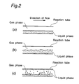
- Fig. 2 shows flow patterns of a gas-liquid separated flow formed in the tubular reactor in the present invention.
- Fig. 1 schematically shows the polymerization process according to the present invention.
- the polymerization process of the invention comprises the steps of:
- separated flow means a flow which is composed of gas-liquid phases, gas-solid phases or gas-liquid-solid phases in a tubular reactor and has a gas phase flow that is substantially continuous in the direction of flow.
- Each of the liquid phase, the solid phase and the solid-liquid phases may form a continuous flow or a discontinuous flow.
- a gas-liquid separated flow or a gas-liquid-solid separated flow is preferable.
- Examples of the separated flows include a stratified flow, a wavy flow, an annular flow and an annular mist flow.
- the gas-liquid separated flow is now described with reference to the attached drawings.
- the stratified flow is a flow formed when a liquid phase flows on the bottom side of a horizontal tube (pipe) and a gas phase flows on the upper side of the tube due to the gravitational effect, and has an almost smooth interface between the gas phase and the liquid phase, as shown in Fig. 2(a).
- the wavy flow is a flow formed when the flow velocity of the gas phase of the stratified flow is increased, and has a wavy interface between the gas phase and the liquid phase, as shown in Fig. 2(b).
- the annular flow is a flow wherein a film of a liquid phase is present along the wall of the tube and a gas phase is formed at the center (core) of a section of the tube.
- the annular mist flow is a flow wherein the gas phase of the annular flow contains droplets, as shown in Fig. 2(c).
- the annular flow or the annular mist flow is particularly preferably formed in the invention.
- an inert medium 4 can be fed to the reactor 1.
- Any of known inert compounds can be widely used as the inert media, with the proviso that they have no adverse influence on the polymerization.
- saturated hydrocarbons of 1 to 20 carbon atoms are employable.
- aliphatic hydrocarbons such as methane, ethane, propane, butane, pentane, hexane, heptane, octane, decane, dodecane and tetradecane
- alicyclic hydrocarbons such as cyclopentane, methylcyclopentane, cyclohexane, methylcyclohexane, cyclooctane and cyclohexane.
- Inert gases such as nitrogen, argon and helium, are also employable as the inert media.
- the raw material monomer and if desired the inert medium are heated by, for example, a heater 5, and fed to the reactor 1 in the pressurized state.
- the pressure at the inlet of the reactor is in the range of usually atmospheric pressure to 100 kg/cm 2 .F, preferably 5 to 50 kg/cm 2 .F.
- the monomer and the inert medium at the inlet la of the reactor need only be in the pressurized state, i.e., have a higher pressure, relative to the pressure in the inside, particularly at the outlet 1b, of the reactor.
- the pressure of the raw material monomer and the inert medium fed to the reactor may be atmospheric pressure at the inlet, if the pressure at the outlet of the reactor is reduced pressure.
- a part of the raw material monomer and the inert medium fed thereto is made to be in a gas phase and the remainder is made to be in a liquid phase, whereby both of the gas phase and the liquid phase are present in the reactor.
- raw material monomers and inert media which can be fed to the reactor, those having, at atmospheric pressure, a boiling point of not higher than 200 °C, preferably not higher than 150 °C, particularly preferably not higher than 100 °C, can form a gas phase in the reactor.
- Examples of the inert media capable of being in a gas phase in the reactor include inert gases, such as nitrogen, and saturated hydrocarbons of 1 to 20 carbon atoms, preferably saturated hydrocarbons of 3 to 10 carbon atoms, from among the aforesaid saturated hydrocarbons.
- inert gases such as nitrogen
- saturated hydrocarbons of 1 to 20 carbon atoms preferably saturated hydrocarbons of 3 to 10 carbon atoms, from among the aforesaid saturated hydrocarbons.
- the gas phase may be formed from only the raw material monomer gas or only the inert gas, or from a mixed gas thereof.
- the gas phase may also contain two or more raw material monomer gases, or two or more inert gases. Further, other gaseous ingredients, such as hydrogen as a molecular weight modifier, may be contained in the gas phase.
- the liquid phase comprises the residual monomer and/or the residual inert medium which do not form the gas phase in the reactor.
- those having a boiling point at atmospheric pressure of not lower than -150 °C, preferably not lower than -40 °C, and not higher than 350 °C can be present in a liquid phase in the reactor.
- saturated hydrocarbons of 1 to 20 carbon atoms preferably saturated hydrocarbons of 3 to 10 carbon atoms, from among the aforesaid saturated hydrocarbons.
- the liquid phase may contain two or more raw material monomers, or two or more inert solvents.
- the liquid phase may further contain a resulting polymer as a solid (in the form of a slurry).
- the raw material monomer and/or the inert medium capable of being in a liquid phase in the reactor is fed to the reactor in such an amount that the volume ratio of the raw material monomer and/or the inert medium capable of being in a liquid phase in the reactor to the raw material monomer and/or the inert medium capable of being in a gas phase in the reactor is in the range of 0.00001 to 100,000, preferably 0.001 to 10,000.
- the catalyst may be fed in any of gas, liquid and solid states.
- the components of the catalyst and the manner to feed the catalyst are described later in detail.
- the components fed to the reactor form the above-mentioned gas-liquid separated flow or gas-liquid-solid separated flow in the reactor, and polymerization of the raw material monomer is performed while the liquid phase or the solid-liquid phases in the reactor is carried by the gas phase (sometimes referred to as "carrier gas” hereinafter) consisting of the raw material monomer and/or the inert medium gas in the reactor.
- the gas phase sometimes referred to as "carrier gas” hereinafter
- the gas linear velocity at the place in the reactor where the gas phase has the lowest gas linear velocity is in the range of usually 0.5 to 500 m/sec, preferably 1 to 300 m/sec, particularly preferably 3 to 150 m/sec.
- the gas linear velocity is determined in the following manner.
- the gas flow rate (volume) at the outlet 1b of the reactor is subjected to temperature/pressure correction and gas-liquid equilibrium calculation to convert it to a gas flow rate (volume) in the reactor.
- the gas flow rate calculated on the assumption that only the gas having this gas flow rate obtained is passed through the reactor is divided by the sectional area of the flow in the reactor, to obtain the gas linear velocity.
- the gas flow rate (volume) at the outlet 1b of the reactor can be determined by connecting the outlet 1b of the reactor to a gas-liquid separator and measuring a flow rate of the gas discharged from a gas discharge tube of the gas-liquid separator.
- the polymerization pressure is desired to be in the range of usually 0.1 to 1,000 kg/cm 2 .F, preferably 1.1 to 100 kg/cm 2 .F, more preferably 1.5 to 80 kg/cm 2 .F, particularly preferably 1.7 to 50 kg/cm 2 .F.
- the polymerization pressure is an average value of the pressure at the inlet la of the reactor and the pressure at the outlet 1b of the reactor.
- the polymerization temperature is desired to be in the range of usually -50 to +300 °C, preferably -20 to +250 °C, particularly preferably 20 to 200 °C.
- the polymer produced is dissolved or suspended in the liquid phase and carried by the carrier gas.
- the raw material monomer contained in the liquid phase in the reactor is consumed for the polymerization, and the inert medium contained therein is heated by heat of the polymerization, whereby a liquid phase composed of only the polymer may be formed at the outlet 1b of the reactor.
- the liquid phase (polymer liquid) obtained at the outlet 1b of the reactor is generally separated into a polymer and a solvent by a polymer separator 6 such as a hopper, and the polymer is then fed to an extruder (not shown).
- the liquid phase (polymer liquid) at the outlet 1b of the reactor contains substantially no solvent or only an extremely small amount of a solvent, and therefore the polymer liquid can be fed directly to the extruder according to circumstances.
- the concentration of the produced polymer in the liquid phase may be a high concentration, such as 100 to 35 % by weight, preferably 90 to 40 % by weight, or it may be lower than this concentration.
- the liquid phase composed of only the polymer or composed of the solvent and the polymer dissolved or suspended in the solvent is obtained.
- the ratio of a flow rate of the liquid phase to a flow rate of the gas phase is in the range of 0.00001 to 100,000, preferably 0.00001 to 10,000, particularly preferably 0.00001 to 1,000.
- the S/G ratio (volume flow rate ratio) can be determined in the following manner.
- the feed rates of the raw material monomer and the inert medium measured at the inlet la of the reactor by means of a flowmeter are subjected to temperature/pressure correction on the basis of the temperature and the pressure in the reactor using an equation of state such as van der Waals equation or virial equation and are subjected to gas-liquid equilibrium calculation using Roult's law or Redilich-Kister equation, to obtain a volume flow rate of the liquid phase and a volume flow rate of the gas phase in the reactor.
- To the volume flow rate of the liquid phase is added a volume flow rate of the polymer to obtain a value S.
- the S/G ratio volume flow rate ratio
- the S/G ratio at the outlet 1b of the reactor may be a mass flow rate, and in this case, the S/G ratio is in the range of 0.00001 to 5,000, preferably 0.0001 to 500, particularly preferably 0.0001 to 50.
- the S/G ratio (mass flow rate ratio) can be determined in the following manner.
- the feed rates of the raw material monomer and the inert medium measured at the inlet la of the reactor by means of a flowmeter are subjected to temperature/pressure correction on the basis of the temperature and the pressure in the reactor using an equation of state such as van der Waals equation or virial equation and are subjected to gas-liquid equilibrium calculation using Roult's law or Redilich-Kister equation, to obtain a mass flow rate of the liquid phase and a mass flow rate of the gas phase in the reactor.
- To the mass flow rate of the liquid phase is added a mass flow rate of the polymer to obtain a value S.
- the S/G ratio mass flow rate ratio
- the pressure loss per unit length in the lengthwise direction of the reaction tube is usually not more than 5 kg/cm 2 ⁇ m, preferably not more than 2 kg/cm 2 ⁇ m, particularly preferably 1 kg/cm 2 ⁇ m.
- the viscosity of the liquid phase obtained from the outlet 1b of the reactor there is no specific limitation on the viscosity of the liquid phase obtained from the outlet 1b of the reactor, and polymer liquids having viscosities over a wide range can be obtained.
- the lower limit of the liquid phase viscosity is not particularly limited, and is usually not less than 1 cp, preferably not less than 10 cp.
- the liquid phase viscosity at the outlet 1b of the reactor namely, viscosity of the polymer substantially produced by the process of the invention, as measured under the conditions of a temperature of 230 °C and a shear rate of 10 sec -1 , is preferably in the range of 1 ⁇ 10 2 to 1 ⁇ 10 6 poise.
- a high viscosity of 3 ⁇ 10 2 to 1 ⁇ 10 6 poise is also preferable, or a viscosity of higher than 1 ⁇ 10 3 poise is available.
- the viscosity can be determined by measuring a shear stress of a molten polymer by means of a capillary type flow property tester (manufactured by Toyo Seiki Seisakusho K.K.) and converting the shear stress to a viscosity. That is, a stress of a molten polymer extruded from a capillary is measured with varying the shear rate, and the measured stress is divided by the shear rate to obtain a viscosity.
- a capillary type flow property tester manufactured by Toyo Seiki Seisakusho K.K.
- the present invention needs no stirring apparatus and is advantageous from the viewpoint of power energy.
- the tubular reactor used in the polymerization process is not specifically limited on its sectional shape, size, etc., as far as the separated flow can be formed in the reactor.
- the inner diameter of the reaction tube (pipe) is about 1 to 50 cm, and the length thereof is about 10 to 500 m.
- Two or more tubular reactors having different diameters may be connected to each other.
- the tubular reactor may be linear or may have a curved portion.
- the tubular reactor may be installed with slope, but it is usually installed horizontally.
- the polymerization conducted in the tubular reactor has excellent energy efficiency, and the heat of reaction can be easily removed.
- a heat exchanger may be provided on the outer periphery of the reactor. It is desirable that a heat medium is passed through the heat exchanger to remove heat of reaction or to heat the reaction system when the reaction needs removal of the reaction heat or needs heating of the system, respectively.
- the heat exchanger is, for example, a jacket, and if necessary, it can be divided into plural parts and provided on the outer periphery of the tubular reactor so that the reaction temperature can be changed in any desired parts of the reaction tube.
- the gas phase or the polymer liquid may be cooled by means of an external heat exchanger and then circulated in the reaction system.
- a monomer feed opening can be appropriately provided at any optional position in the lengthwise direction of the reaction tube to feed copolymerizable monomers. If the monomers are fed to the reaction tube at such an position, polymers comprising various copolymerized components can be produced by a single reactor.
- Examples of the raw material monomers used in the invention include olefins.
- straight-chain, branched or cyclic olefins of 2 to 20 carbon atoms such as ethylene, propylene, 1-butene, 1-pentene, 1-hexene, 4-methyl-1-pentene, 1-octene, 1-decene, 1-dodecene, norbornene, tetracyclododecene and methyltetracyclododecene, can be homopolymerized or copolymerized in the olefin polymerization.
- the olefins may be copolymerized with non-conjugated dienes.
- Examples of the copolymerizable dienes include cyclic dienes, such as 5-ethylidene-2-norbornene, 5-propylidene-2-norbornene, dicyclopentadiene and 5-vinyl-2-norbornene; and chain non-conjugated dienes, such as 1,4-hexadiene, 5-methyl-1,5-heptadiene, 6-methyl-1,5-heptadiene, 6-methyl-1,7-octadiene and 7-methyl-1,6-octadiene.
- cyclic dienes such as 5-ethylidene-2-norbornene, 5-propylidene-2-norbornene, dicyclopentadiene and 5-vinyl-2-norbornene
- chain non-conjugated dienes such as 1,4-hexadiene, 5-methyl-1,5-heptadiene, 6-methyl-1,5-heptadiene, 6-methyl-1,7-oct
- the aromatic vinyl monomers such as styrene may be polymerized.
- any of catalysts generally used for polymerization are employable in the invention.
- an olefin polymerization catalyst comprising, for example, a transition metal catalyst component and a cocatalyst component as described below is preferably employed.
- the transition metal catalyst component used herein is a transition metal compound (A) containing a transition metal selected from Group IVB of the periodic table.
- the transition metal compound (A) may be represented by, for example, the following formula (i): MLx wherein M is a transition metal selected from Zr, Ti, Hf, V, Nb, Ta and Cr; L is a ligand coordinating to the transition metal, specifically, a hydrogen atom, a halogen atom, an oxygen atom, a hydrocarbon group of 1 to 30 carbon atoms which may have a substituent, an alkoxy group, an aryloxy group, a trialkylsilyl group or a SO 3 R group (where R is a hydrocarbon group of 1 to 8 carbon atoms which may have a substituent such as halogen); and x is a valence of the transition metal.
- halogen atoms examples include fluorine, chlorine, bromine and iodine.
- hydrocarbon groups of 1 to 30 carbon atoms examples include alkyl groups, such as methyl, ethyl, propyl, isopropyl and butyl; cycloalkyl groups, such as cyclopentyl and cyclohexyl; aryl groups, such as phenyl, tolyl and cyclopentadienyl; and aralkyl groups, such as benzyl and neophyl.
- cycloalkyl groups, aryl groups and aralkyl groups may be substituted in part with halogen atoms, alkyl groups and trialkylsilyl groups.
- hydrocarbon groups selected from cycloalkyl groups, aryl groups and aralkyl groups When plural hydrocarbon groups selected from cycloalkyl groups, aryl groups and aralkyl groups are coordinated, they may be bonded through an alkylene group, such as ethylene or propylene, a substituted alkylene group, such as isopropylidene or diphenylmethylene, a silylene group, or a substituted silylene group, such as dimethylsilylene, diphenylsilylene or methylphenylsilylene.
- alkylene group such as ethylene or propylene
- a substituted alkylene group such as isopropylidene or diphenylmethylene
- silylene group a substituted silylene group
- dimethylsilylene, diphenylsilylene or methylphenylsilylene such as dimethylsilylene, diphenylsilylene or methylphenylsilylene.
- alkoxy groups include methoxy, ethoxy and butoxy.
- aryloxy groups include phenoxy.
- the transition metal compounds may be used singly or in combination of two or more. Further, they may be used after diluted with hydrocarbons or halogenated hydrocarbons.
- the transition metal compound can be used in the form of a solid in the polymerization system.
- the transition metal compound can be used together with a particulate carrier compound by contacting it with the carrier compound.
- the carrier compounds include inorganic compounds, such as SiO 2 , Al 2 O 3 , B 2 O 3 , MgO, ZrO 2 , CaO, TiO 2 , ZnO, Zn 2 O, SnO 2 , BaO, MgCl 2 and NaCl; and resins, such as polyethylene, polypropylene, poly-1-butene, poly-4-methyl-1-pentene and a styrene/divinylbenzene copolymer.
- These carrier compounds can be used in combination of two or more kinds.
- the carrier compounds may be made particulate in the course of contacting them with the transition metal compound.
- MgCl 2 and SiO 2 are particularly preferable.
- the cocatalyst component for forming the olefin polymerization catalyst is a compound (B) selected from an organoaluminum compound, an organoaluminum halide compound, an aluminum halide compound, an organoboron compound, an organoboron oxy-compound, an organoboron halide compound, a boron halide compound and an organoaluminum oxy-compound.
- These compounds (B), except the organoaluminum oxy-compound, may be represented by the following formula (ii): BRx wherein B is an aluminum atom or a boron atom, and x is a valence of the aluminum atom or the boron atom.
- R indicates an alkyl group of 1 to 30 carbon atoms.
- R indicates a halogen atom.
- R indicates both of an alkyl group of 1 to 30 carbon atoms and a halogen atom.
- halogen atoms include fluorine, chlorine, bromine and iodine.
- alkyl groups of 1 to 30 carbon atoms include methyl, ethyl, propyl, isopropyl, butyl and isobutyl.
- the organoaluminum oxy-compound may be represented by the following formula (iii) or (iv): wherein R is a hydrocarbon group, such as methyl, ethyl, propyl or butyl, and m is an integer of not less than 2, preferably 5 to 40.
- the alkyloxyaluminum unit (OAl(R)) may consist of a unit of the formula (OAl(R 1 )) wherein R 1 is the same group as defined for R, and a unit of the formula (OAI(R 2 )) wherein R 2 is the same group as defined for R but is different from R 1 , in combination.
- a part of the groups R in the alkyloxyaluminum units may be replaced by halogen, hydrogen, an alkoxy group, an aryloxy group or a hydroxyl group.
- cocatalyst compounds (B) mentioned above may be used singly or in combination of two or more. Further, they may be used after diluted with hydrocarbons or halogenated hydrocarbons.
- olefin polymerization catalysts comprising an appropriate combination of the transition metal compound catalyst component and the cocatalyst component include Ziegler catalysts, metallocene catalysts and vanadium catalysts.
- the olefin polymerization catalyst may optionally contain an electron donor in addition to the transition metal catalyst component (A) and the cocatalyst component (B).
- electron donors include ether compounds, carbonyl compounds and alkoxy compounds.
- a prepolymerized catalyst obtained by prepolymerizing an olefin onto the above catalyst components can be employed.
- a prepolymerized catalyst in which an olefin is prepolymerized onto a catalyst comprising the transition metal catalyst component and the cocatalyst component, in an amount of 50 to 500 g, preferably 300 to 3,000 g, based on 1 g of the transition metal catalyst component, is preferably employed.
- the transition metal catalyst component used for the prepolymerization is preferably supported on a particulate carrier compound as mentioned above.
- an electron donor can be used if necessary.
- Examples of the olefins to be prepolymerized include those as mentioned above for the raw material monomers used in the main polymerization.
- the olefin used in the prepolymerization may be the same or different from the olefin used in the main polymerization. Two or more olefins can be prepolymerized.
- the prepolymerization can be carried out in such a state that the olefin becomes liquid, or in the presence of an inert solvent, or under the gas phase conditions. It is preferable that the olefin to be prepolymerized and the catalyst components are added to an inert solvent and the prepolymerization is carried out under relatively mild conditions.
- the prepolymerization conditions may be those under which the resulting prepolymer is dissolved or is not dissolved in the solvent. Preferred conditions are those under which the resulting prepolymer is not dissolved.
- the prepolymerization can be carried out by any of batchwise, semi-continuous and continuous processes.
- the concentrations of the catalyst components in the prepolymerization vary depending upon the types of the catalyst components, but it is preferred to employ the transition metal catalyst component in a concentration, in terms of a transition metal atom, of usually about 0.001 to 5,000 mmol, preferably about 0.01 to 1,000 mmol, particularly preferably 0.1 to 500 mmol based on 1 liter of the polymerization volume.
- the cocatalyst component can be used in an amount of usually about 0.1 to 1,000 mol, preferably about 0.5 to 500 mol, particularly preferably 1 to 100 mol, based on 1 mol of the transition metal atom in the transition metal catalyst component.
- a molecular weight modifier such as hydrogen can be employed.
- the suspension can be fed as it is to the reactor, or a prepolymerized catalyst can be separated from the suspension and fed to the reactor.
- the prepolymerized catalyst preferably has a particle diameter of not less than 10 ⁇ m, more preferably 50 to 500 ⁇ m.
- the cocatalyst component can be fed to the reactor together with the prepolymerized catalyst. According to circumstances, however, the cocatalyst component does not need to be fed to the reactor.
- polymerization of the raw material monomer is performed while carrying the liquid phase by the gas phase flow in the tubular reactor, as described above.
- a catalyst containing the prepolymerized olefin in the above-mentioned amount is used in the polymerization, the catalyst fed to the reactor can exhibit excellent efficiency.
- the catalyst may sometimes undergo short-pass by the gas phase flow in the reactor, so that the ability of the catalyst may not be fully exhibited.
- the cocatalyst component is preferably fed together with an inert solvent by previously mixing it with the inert solvent.
- Examples of the inert solvents mixed with the cocatalyst component include the aforementioned inert solvents which are fed to the reactor.
- the solvent mixed with the cocatalyst is preferably the same solvent as fed to the reactor.
- the premixing of the cocatalyst component with the inert solvent is made so that the cocatalyst and the inert solvent are uniformly mixed. Specifically, the premixing is carried out by adding the cocatalyst component to the inert solvent and stirring them at 5 to 60 °C for 0.5 to 24 hours.
- the inert solvent is preferably used in an amount of 250 to 2.5 ⁇ 10 7 ml based on 1 g of the cocatalyst component.
- the premixing may be carried out batchwise or continuously.
- the cocatalyst component having been premixed with the inert solvent is fed to the reactor, the cocatalyst component can sufficiently be dispersed in the reaction system, and thereby the cocatalyst component fed to the reactor can be used effectively. Accordingly, the amount of the cocatalyst component fed to the rector is only the minimum amount (calculated value) necessary for the reaction.
- Feeding of an excess amount of the cocatalyst component to the reactor may cause decrease of the activity of the transition metal catalyst component thereby to lower the polymerization activity based on the transition metal.
- the molecular weight of the resulting polyolefin can be controlled by varying the polymerization conditions such as polymerization temperature or the amount of a molecular weight modifier (e.g., hydrogen) used.
- a molecular weight modifier e.g., hydrogen
- an ethylene/ ⁇ -olefin elastomer having a wide molecular weight distribution can be prepared.
- the polymerization process of the invention is particularly suitable for preparing a polymer having a density of 0.800 to 1.100 g/cm 3 , preferably 0.820 to 1.080 g/cm 3 , more preferably 0.830 to 1.050 g/cm 3 .
- the polymer obtained by the invention desirably has an elastic modulus of 1 to 1 ⁇ 10 4 MPa, preferably 2 to 5 ⁇ 10 3 MPa, more preferably 2 to 3 ⁇ 10 3 MPa.
- the elastic modulus of the polymer is so-called flexural modulus, and is measured using a specimen having a thickness of 2 mm under the conditions of a span of 32 mm and a flexural rate of 5 mm/min in accordance with ASTM C790.
- the polymerization can be accomplished with particularly excellent thermal efficiency. For example, even if a reaction with a large quantity of exothermic heat is conducted, the heat can be removed by means of only a jacket of the reactor.
- the separated flow has a gas phase that is continuous in the direction of flow in the reactor, and the gas phase flow carries a liquid phase. Therefore, even if the resulting polymer is dissolved in the liquid phase to give a high-viscosity solution, the solution can be carried by only the carrier gas in the reaction tube so that the reaction tube is hardly clogged. Thus, there is no need to provide any additional carrying means (power) such as a circulating pump and to stir the high-viscosity solution, and hence, the polymerization can be accomplished by small power energy.
- power such as a circulating pump and to stir the high-viscosity solution
- the liquid phase (polymer liquid) at the outlet 1b of the reactor does not substantially contain a solvent or contains only an extremely small amount of a solvent, equipment for drying the resulting polymer can be greatly simplified.
- the polymer solution can be directly introduced into an extruder, and the procedure for recycling the solvent can be simplified.
- the polymerization can be accomplished by a simple tubular reactor without using any specific large-scale equipment, such as a large-sized stirring machine, a dryer and a high-pressure compression apparatus. That is, the polymerization can be accomplished at low costs of apparatuses. Besides, there are few restrictions on the viscosity and the melting point of the resulting polymer.
- reaction temperature can easily be controlled in the lengthwise direction of the tube, and an additional comonomer can be fed at an optional position in the lengthwise direction of the reaction tube. Therefore, polymers having various properties can be prepared using a single tubular reactor.
- the S/G ratio (volume flow rate ratio) was determined in the following manner.
- the gas-liquid equilibrium at the temperature and the pressure in the reactor was calculated using the known Redlich-Kister equation of state on the basis of the amounts and compositions of the materials (monomer, solvent, etc.) fed to the reactor, to obtain a volume flow rate of the liquid phase and a volume flow rate of the gas phase in the reactor.
- the MI of polyethylene obtained in each example was measured at 190 °C under a load of 2.16 kg in accordance with ASTM D1238.
- raw material monomers i.e., ethylene and an ⁇ -olefin of 6 carbon atoms (4-methyl-1-pentene), a Ziegler type titanium prepolymerized catalyst (containing 2,000 g of prepolymerized ethylene per 1 g of a transition metal compound catalyst component), an alkylaluminum and n-decane, to copolymerize the raw material monomers under the following conditions.
- raw material monomers i.e., ethylene and an ⁇ -olefin of 6 carbon atoms (4-methyl-1-pentene
- a Ziegler type titanium prepolymerized catalyst containing 2,000 g of prepolymerized ethylene per 1 g of a transition metal compound catalyst component
- an alkylaluminum and n-decane alkylaluminum and n-decane
- high-quality polyethylene was obtained in an amount of 190,000 g per 1 g of the transition metal compound catalyst component in the prepolymerized catalyst and at a flow rate of 0.5 kg/hr at the outlet of the reactor.
- the resulting polyethylene had a MI of 5 g/10 min and a density of 0.95 g/cm 3 .
- Polymerization was carried out in the same manner as in Example 1, except that the polymerization conditions were varied to the following conditions.
- high-quality polyethylene was obtained in an amount of 400,000 g per 1 g of the transition metal compound catalyst component and at a flow rate of 0.1 kg/hr at the outlet of the reactor.
- the resulting polyethylene had a MI of 35 g/10 min and a density of 0.89 g/cm 3 .
- polyethylene was obtained in an amount of 146,000 g per 1 g of the transition metal compound catalyst component at the outlet of the reactor.
- the resulting polyethylene had a MI of 1.0 g/10 min and a density of 0.96 g/cm 3 .
- Polymerization of ethylene was carried out in the same manner as in Example 3, except that a premixture obtained by premixing an alkylaluminum and 90 ml of n-dacane based on 1 mg of the alkylaluminum at room temperature for 1 hour (residence time) was fed to the reactor.
- the raw material monomer (ethylene), the same prepolymerized catalyst as used in Example 1 and the premixture of alkylaluminum and n-decane as obtained above were fed to a tubular reactor (steel tube of 1/2B ⁇ 25 m + 5/6B ⁇ 15 m), to polymerize the raw material monomer under the following conditions.
- high-quality polyethylene was obtained in an amount of 293,000 g per 1 g of the transition metal compound catalyst component and at a flow rate of 0.8 kg/hr at the outlet of the reactor.
- the resulting polyethylene had a MI of 2 g/10 min and a density of 0.96 g/cm 3 .
- the concentration of the polymer liquid had to be decreased to not more than 20 % by weight to ensure good mixing of the polymerization system so as to maintain the product quality.
Abstract
Description


Claims (7)
- A polymerisation process comprising feeding monomer, polymerisation catalyst and, optionally, an inert medium, to a reactor maintained under pressure and polymerising the monomer so as to form a polymer wherein the monomer, polymer and any inert medium are permitted to form a gas-liquid or gas-liquid-solid separated flow, the gas phase of the separated flow being continuous in the direction of flow and the liquid phase being carried by the gas flow, the ratio of the volume flow rate of the liquid phase to the volume flow rate of the gas phase at the outlet of the reactor being from 0.00001:1 to 100,000:1.
- A process as claimed in claim 1, wherein the separated flow is a stratified flow, a wavy flow, an annular flow or an annular mist flow.
- A process as claimed in claim 2, wherein the separated flow is an annular flow or an annular mist flow.
- A process as claimed in any one of claims 1 to 3, wherein a heat exchanger is provided on the outer periphery of the tubular reactor and a heat medium is passed through the heat exchanger to heat or cool the reactor.
- A process as claimed in any one of claims 1 to 4, wherein the monomer is an olefin.
- A process as claimed in claim 5, wherein the polymerization catalyst comprises a transition metal catalyst component, in which the transition metal is the selected from zirconium, titanium and hafnium, a cocatalyst component and prepolymerized olefin in an amount of 50 to 5,000 g per 1 g of the transition metal catalyst component.
- A process as claimed in claim 5, comprising feeding a prepolymerized catalyst, olefin and the cocatalyst component to the reactor, the cocatalyst component being fed as a mixture with an inert solvent.
Applications Claiming Priority (6)
| Application Number | Priority Date | Filing Date | Title |
|---|---|---|---|
| JP34819596 | 1996-12-26 | ||
| JP348195/96 | 1996-12-26 | ||
| JP34819596 | 1996-12-26 | ||
| JP25703697A JP3836228B2 (en) | 1996-12-26 | 1997-09-22 | Polymerization method with separated flow |
| JP25703697 | 1997-09-22 | ||
| JP257036/97 | 1997-09-22 |
Publications (3)
| Publication Number | Publication Date |
|---|---|
| EP0850962A2 true EP0850962A2 (en) | 1998-07-01 |
| EP0850962A3 EP0850962A3 (en) | 1998-07-08 |
| EP0850962B1 EP0850962B1 (en) | 2001-10-31 |
Family
ID=26543025
Family Applications (1)
| Application Number | Title | Priority Date | Filing Date |
|---|---|---|---|
| EP97310552A Expired - Lifetime EP0850962B1 (en) | 1996-12-26 | 1997-12-23 | Polymerization process using separated flow |
Country Status (10)
| Country | Link |
|---|---|
| US (1) | US6111035A (en) |
| EP (1) | EP0850962B1 (en) |
| JP (1) | JP3836228B2 (en) |
| KR (1) | KR19980064551A (en) |
| CN (1) | CN1218968C (en) |
| CA (1) | CA2225639A1 (en) |
| DE (1) | DE69707826T2 (en) |
| ID (1) | ID19349A (en) |
| MY (1) | MY117027A (en) |
| TW (1) | TW442499B (en) |
Cited By (15)
| Publication number | Priority date | Publication date | Assignee | Title |
|---|---|---|---|---|
| US6815525B2 (en) | 2000-12-07 | 2004-11-09 | Eastamn Chemical Company | Component introduction into manufacturing process through recirculation |
| US7649109B2 (en) | 2006-12-07 | 2010-01-19 | Eastman Chemical Company | Polyester production system employing recirculation of hot alcohol to esterification zone |
| US7718759B2 (en) | 2000-12-07 | 2010-05-18 | Eastman Chemical Company | Polyester process using a pipe reactor |
| US7829653B2 (en) | 2007-07-12 | 2010-11-09 | Eastman Chemical Company | Horizontal trayed reactor |
| US7842777B2 (en) | 2007-07-12 | 2010-11-30 | Eastman Chemical Company | Sloped tubular reactor with divided flow |
| US7847053B2 (en) | 2007-07-12 | 2010-12-07 | Eastman Chemical Company | Multi-level tubular reactor with oppositely extending segments |
| US7858730B2 (en) | 2007-07-12 | 2010-12-28 | Eastman Chemical Company | Multi-level tubular reactor with dual headers |
| US7863477B2 (en) | 2007-03-08 | 2011-01-04 | Eastman Chemical Company | Polyester production system employing hot paste to esterification zone |
| US7868130B2 (en) | 2007-07-12 | 2011-01-11 | Eastman Chemical Company | Multi-level tubular reactor with vertically spaced segments |
| US7868129B2 (en) | 2007-07-12 | 2011-01-11 | Eastman Chemical Company | Sloped tubular reactor with spaced sequential trays |
| US7872090B2 (en) | 2007-07-12 | 2011-01-18 | Eastman Chemical Company | Reactor system with optimized heating and phase separation |
| US7872089B2 (en) | 2007-07-12 | 2011-01-18 | Eastman Chemical Company | Multi-level tubular reactor with internal tray |
| US7943094B2 (en) | 2006-12-07 | 2011-05-17 | Grupo Petrotemex, S.A. De C.V. | Polyester production system employing horizontally elongated esterification vessel |
| WO2012005519A2 (en) * | 2010-07-09 | 2012-01-12 | 대림산업 주식회사 | Method for polymerizing alpha-olefins with utilizing three-phase system, using three-phase fluidized-bed reactor |
| EP3088388A1 (en) | 2015-04-30 | 2016-11-02 | NicOx S.A. | Nitric oxide donating derivatives of prostaglandins |
Families Citing this family (7)
| Publication number | Priority date | Publication date | Assignee | Title |
|---|---|---|---|---|
| US7135541B2 (en) * | 2003-06-06 | 2006-11-14 | Eastman Chemical Company | Polyester process using a pipe reactor |
| JP2010540629A (en) * | 2007-10-04 | 2010-12-24 | メルク・シャープ・エンド・ドーム・コーポレイション | Substituted arylsulfone derivatives as calcium channel blockers |
| US20100113692A1 (en) * | 2008-11-04 | 2010-05-06 | Mcguire Jr James E | Apparatus for Continuous Production of Partially Polymerized Compositions |
| CN101928197A (en) * | 2009-06-26 | 2010-12-29 | 中国石油化工股份有限公司 | Method for thermal dimerization of cyclopentadiene |
| JP5888722B2 (en) * | 2010-08-23 | 2016-03-22 | 株式会社明治 | In-line continuous measurement method and apparatus for overrun of food and drink, and method for producing food and drink using the measurement method, and food and drink produced thereby |
| CN103333278B (en) * | 2013-01-30 | 2016-02-24 | 衢州市鼎盛化工科技有限公司 | A kind of device and technique thereof preparing fluoropolymer and fluorinated copolymer |
| CN103446990B (en) * | 2013-08-29 | 2015-12-23 | 中国化学赛鼎宁波工程有限公司 | Tangential circulation tubular type heterogeneous reaction device |
Citations (4)
| Publication number | Priority date | Publication date | Assignee | Title |
|---|---|---|---|---|
| FR1551857A (en) * | 1966-11-26 | 1969-01-03 | ||
| US4089888A (en) * | 1976-07-12 | 1978-05-16 | Idemitsu Petrochemical Co. Ltd. | Method for producing a polycarbonate oligomer |
| US4352923A (en) * | 1979-11-06 | 1982-10-05 | Ube Industries, Ltd. | Process for polymerizing formaldehyde |
| US5644007A (en) * | 1996-04-26 | 1997-07-01 | Minnesota Mining And Manufacturing Company | Continuous process for the production of poly(1-alkenes) |
Family Cites Families (7)
| Publication number | Priority date | Publication date | Assignee | Title |
|---|---|---|---|---|
| US4133944A (en) * | 1973-03-29 | 1979-01-09 | Imperial Chemical Industries Limited | Ethylene polymerization |
| FR2385745A1 (en) * | 1977-03-31 | 1978-10-27 | Charbonnages Ste Chimique | ETHYLENE POLYMERIZATION PROCESS, UNDER HIGH PRESSURE, WITH RECYCLING |
| DE2719967A1 (en) * | 1977-05-04 | 1978-11-09 | Bayer Ag | CONTINUOUS PROCEDURE FOR CARRYING OUT SUBSTANCE TRANSPORT-RELATED REACTIONS |
| US5243005A (en) * | 1988-09-07 | 1993-09-07 | Mitsui Petrochemical Industries, Ltd. | Process for producing cycloolefin random copolymers |
| FR2659338B1 (en) * | 1990-03-09 | 1993-05-07 | Bp Chemicals Snc | METHODS AND DEVICES FOR CATALYTIC POLYMERIZATION OF ALPHA-OLEFINS IN THE GAS PHASE. |
| US5589555A (en) * | 1991-10-03 | 1996-12-31 | Novacor Chemicals (International) S.A. | Control of a solution process for polymerization of ethylene |
| US5859157A (en) * | 1996-10-16 | 1999-01-12 | Equistar Chemicals, Lp | Process for gas phase polymerization of olefins |
-
1997
- 1997-09-22 JP JP25703697A patent/JP3836228B2/en not_active Expired - Fee Related
- 1997-12-16 MY MYPI97006067A patent/MY117027A/en unknown
- 1997-12-18 US US08/993,525 patent/US6111035A/en not_active Expired - Fee Related
- 1997-12-23 DE DE69707826T patent/DE69707826T2/en not_active Expired - Fee Related
- 1997-12-23 CA CA002225639A patent/CA2225639A1/en not_active Abandoned
- 1997-12-23 EP EP97310552A patent/EP0850962B1/en not_active Expired - Lifetime
- 1997-12-24 ID IDP973979A patent/ID19349A/en unknown
- 1997-12-24 KR KR1019970073036A patent/KR19980064551A/en active IP Right Grant
- 1997-12-24 TW TW086119660A patent/TW442499B/en not_active IP Right Cessation
- 1997-12-26 CN CNB971263361A patent/CN1218968C/en not_active Expired - Fee Related
Patent Citations (4)
| Publication number | Priority date | Publication date | Assignee | Title |
|---|---|---|---|---|
| FR1551857A (en) * | 1966-11-26 | 1969-01-03 | ||
| US4089888A (en) * | 1976-07-12 | 1978-05-16 | Idemitsu Petrochemical Co. Ltd. | Method for producing a polycarbonate oligomer |
| US4352923A (en) * | 1979-11-06 | 1982-10-05 | Ube Industries, Ltd. | Process for polymerizing formaldehyde |
| US5644007A (en) * | 1996-04-26 | 1997-07-01 | Minnesota Mining And Manufacturing Company | Continuous process for the production of poly(1-alkenes) |
Cited By (19)
| Publication number | Priority date | Publication date | Assignee | Title |
|---|---|---|---|---|
| US7718759B2 (en) | 2000-12-07 | 2010-05-18 | Eastman Chemical Company | Polyester process using a pipe reactor |
| US6815525B2 (en) | 2000-12-07 | 2004-11-09 | Eastamn Chemical Company | Component introduction into manufacturing process through recirculation |
| US7842778B2 (en) | 2000-12-07 | 2010-11-30 | Eastman Chemical Company | Polyester process using a pipe reactor |
| US8114954B2 (en) | 2000-12-07 | 2012-02-14 | Grupo Petrotemex, S.A. De C.V. | Polyester process using a pipe reactor |
| US7649109B2 (en) | 2006-12-07 | 2010-01-19 | Eastman Chemical Company | Polyester production system employing recirculation of hot alcohol to esterification zone |
| US8470250B2 (en) | 2006-12-07 | 2013-06-25 | Grupo Petrotemex, S.A. De C.V. | Polyester production system employing horizontally elongated esterification vessel |
| US7943094B2 (en) | 2006-12-07 | 2011-05-17 | Grupo Petrotemex, S.A. De C.V. | Polyester production system employing horizontally elongated esterification vessel |
| US7863477B2 (en) | 2007-03-08 | 2011-01-04 | Eastman Chemical Company | Polyester production system employing hot paste to esterification zone |
| US7842777B2 (en) | 2007-07-12 | 2010-11-30 | Eastman Chemical Company | Sloped tubular reactor with divided flow |
| US7868130B2 (en) | 2007-07-12 | 2011-01-11 | Eastman Chemical Company | Multi-level tubular reactor with vertically spaced segments |
| US7868129B2 (en) | 2007-07-12 | 2011-01-11 | Eastman Chemical Company | Sloped tubular reactor with spaced sequential trays |
| US7872090B2 (en) | 2007-07-12 | 2011-01-18 | Eastman Chemical Company | Reactor system with optimized heating and phase separation |
| US7872089B2 (en) | 2007-07-12 | 2011-01-18 | Eastman Chemical Company | Multi-level tubular reactor with internal tray |
| US7858730B2 (en) | 2007-07-12 | 2010-12-28 | Eastman Chemical Company | Multi-level tubular reactor with dual headers |
| US7847053B2 (en) | 2007-07-12 | 2010-12-07 | Eastman Chemical Company | Multi-level tubular reactor with oppositely extending segments |
| US7829653B2 (en) | 2007-07-12 | 2010-11-09 | Eastman Chemical Company | Horizontal trayed reactor |
| WO2012005519A2 (en) * | 2010-07-09 | 2012-01-12 | 대림산업 주식회사 | Method for polymerizing alpha-olefins with utilizing three-phase system, using three-phase fluidized-bed reactor |
| WO2012005519A3 (en) * | 2010-07-09 | 2012-05-03 | 대림산업 주식회사 | Method for polymerizing alpha-olefins with utilizing three-phase system, using three-phase fluidized-bed reactor |
| EP3088388A1 (en) | 2015-04-30 | 2016-11-02 | NicOx S.A. | Nitric oxide donating derivatives of prostaglandins |
Also Published As
| Publication number | Publication date |
|---|---|
| DE69707826T2 (en) | 2002-04-11 |
| KR19980064551A (en) | 1998-10-07 |
| CN1186077A (en) | 1998-07-01 |
| TW442499B (en) | 2001-06-23 |
| EP0850962A3 (en) | 1998-07-08 |
| CA2225639A1 (en) | 1998-06-26 |
| US6111035A (en) | 2000-08-29 |
| DE69707826D1 (en) | 2001-12-06 |
| ID19349A (en) | 1998-07-02 |
| MY117027A (en) | 2004-04-30 |
| JP3836228B2 (en) | 2006-10-25 |
| JPH10237112A (en) | 1998-09-08 |
| EP0850962B1 (en) | 2001-10-31 |
| CN1218968C (en) | 2005-09-14 |
Similar Documents
| Publication | Publication Date | Title |
|---|---|---|
| EP0850962B1 (en) | Polymerization process using separated flow | |
| KR101233961B1 (en) | Slurry phase polymerisation process | |
| US5126414A (en) | Control of oligomer level in low pressure polyethylene reactor systems | |
| KR101245399B1 (en) | Slurry phase polymerisation process | |
| EP0634421A1 (en) | Process for gas phase polymerization of olefin | |
| KR20090017544A (en) | Loop type reactor for polymerization | |
| KR101235468B1 (en) | Slurry phase polymerisation process | |
| KR20100059833A (en) | Slurry phase polymerisation process | |
| EP1348719B1 (en) | Process for producing polyolefin | |
| JP3315746B2 (en) | Olefin polymerization method | |
| EP1278783B1 (en) | Olefin polymerization process | |
| JP4212938B2 (en) | Method for producing polyolefin | |
| JP2000007710A (en) | Preparation of polymer | |
| RU2440842C2 (en) | Circulation reactor polymerisation | |
| JP2000072802A (en) | Vapor phase polymerization apparatus | |
| EP0723976A2 (en) | Dry prepolymerized catalyst for olefin polymerization, process for preparing the same and gas phase olefin polymerization process | |
| JPH0977811A (en) | Vapor-phase polymerization of olefin | |
| JP2003192705A (en) | Method for producing olefin polymer | |
| JP2001098005A (en) | Method for gas-phase polymerization of olefin | |
| WO2007034847A1 (en) | Method for producing olefin polymer |
Legal Events
| Date | Code | Title | Description |
|---|---|---|---|
| PUAI | Public reference made under article 153(3) epc to a published international application that has entered the european phase |
Free format text: ORIGINAL CODE: 0009012 |
|
| PUAL | Search report despatched |
Free format text: ORIGINAL CODE: 0009013 |
|
| AK | Designated contracting states |
Kind code of ref document: A2 Designated state(s): DE FR GB IT NL |
|
| AX | Request for extension of the european patent |
Free format text: AL;LT;LV;MK;RO;SI |
|
| AK | Designated contracting states |
Kind code of ref document: A3 Designated state(s): AT BE CH DE DK ES FI FR GB GR IE IT LI LU MC NL PT SE |
|
| AX | Request for extension of the european patent |
Free format text: AL;LT;LV;MK;RO;SI |
|
| 17P | Request for examination filed |
Effective date: 19980909 |
|
| AKX | Designation fees paid |
Free format text: DE FR GB IT NL |
|
| RBV | Designated contracting states (corrected) |
Designated state(s): DE FR GB IT NL |
|
| 17Q | First examination report despatched |
Effective date: 19990511 |
|
| GRAG | Despatch of communication of intention to grant |
Free format text: ORIGINAL CODE: EPIDOS AGRA |
|
| GRAG | Despatch of communication of intention to grant |
Free format text: ORIGINAL CODE: EPIDOS AGRA |
|
| GRAH | Despatch of communication of intention to grant a patent |
Free format text: ORIGINAL CODE: EPIDOS IGRA |
|
| GRAH | Despatch of communication of intention to grant a patent |
Free format text: ORIGINAL CODE: EPIDOS IGRA |
|
| GRAH | Despatch of communication of intention to grant a patent |
Free format text: ORIGINAL CODE: EPIDOS IGRA |
|
| GRAH | Despatch of communication of intention to grant a patent |
Free format text: ORIGINAL CODE: EPIDOS IGRA |
|
| GRAA | (expected) grant |
Free format text: ORIGINAL CODE: 0009210 |
|
| AK | Designated contracting states |
Kind code of ref document: B1 Designated state(s): DE FR GB IT NL |
|
| REF | Corresponds to: |
Ref document number: 69707826 Country of ref document: DE Date of ref document: 20011206 |
|
| REG | Reference to a national code |
Ref country code: GB Ref legal event code: IF02 |
|
| ET | Fr: translation filed | ||
| PLBE | No opposition filed within time limit |
Free format text: ORIGINAL CODE: 0009261 |
|
| STAA | Information on the status of an ep patent application or granted ep patent |
Free format text: STATUS: NO OPPOSITION FILED WITHIN TIME LIMIT |
|
| 26N | No opposition filed | ||
| PGFP | Annual fee paid to national office [announced via postgrant information from national office to epo] |
Ref country code: NL Payment date: 20031205 Year of fee payment: 7 |
|
| PGFP | Annual fee paid to national office [announced via postgrant information from national office to epo] |
Ref country code: FR Payment date: 20031210 Year of fee payment: 7 |
|
| PGFP | Annual fee paid to national office [announced via postgrant information from national office to epo] |
Ref country code: GB Payment date: 20031217 Year of fee payment: 7 |
|
| PG25 | Lapsed in a contracting state [announced via postgrant information from national office to epo] |
Ref country code: GB Free format text: LAPSE BECAUSE OF NON-PAYMENT OF DUE FEES Effective date: 20041223 |
|
| PG25 | Lapsed in a contracting state [announced via postgrant information from national office to epo] |
Ref country code: NL Free format text: LAPSE BECAUSE OF NON-PAYMENT OF DUE FEES Effective date: 20050701 |
|
| GBPC | Gb: european patent ceased through non-payment of renewal fee |
Effective date: 20041223 |
|
| PG25 | Lapsed in a contracting state [announced via postgrant information from national office to epo] |
Ref country code: FR Free format text: LAPSE BECAUSE OF NON-PAYMENT OF DUE FEES Effective date: 20050831 |
|
| NLV4 | Nl: lapsed or anulled due to non-payment of the annual fee |
Effective date: 20050701 |
|
| REG | Reference to a national code |
Ref country code: FR Ref legal event code: ST |
|
| PGFP | Annual fee paid to national office [announced via postgrant information from national office to epo] |
Ref country code: IT Payment date: 20081224 Year of fee payment: 12 |
|
| PGFP | Annual fee paid to national office [announced via postgrant information from national office to epo] |
Ref country code: DE Payment date: 20081219 Year of fee payment: 12 |
|
| PG25 | Lapsed in a contracting state [announced via postgrant information from national office to epo] |
Ref country code: DE Free format text: LAPSE BECAUSE OF NON-PAYMENT OF DUE FEES Effective date: 20100701 |
|
| PG25 | Lapsed in a contracting state [announced via postgrant information from national office to epo] |
Ref country code: IT Free format text: LAPSE BECAUSE OF NON-PAYMENT OF DUE FEES Effective date: 20091223 |