EP0849703B1 - Mobile information carrier readable by machine - Google Patents
Mobile information carrier readable by machine Download PDFInfo
- Publication number
- EP0849703B1 EP0849703B1 EP97122217A EP97122217A EP0849703B1 EP 0849703 B1 EP0849703 B1 EP 0849703B1 EP 97122217 A EP97122217 A EP 97122217A EP 97122217 A EP97122217 A EP 97122217A EP 0849703 B1 EP0849703 B1 EP 0849703B1
- Authority
- EP
- European Patent Office
- Prior art keywords
- information
- flow line
- energy
- information carrier
- machine
- Prior art date
- Legal status (The legal status is an assumption and is not a legal conclusion. Google has not performed a legal analysis and makes no representation as to the accuracy of the status listed.)
- Expired - Lifetime
Links
Images

Classifications
-
- G—PHYSICS
- G06—COMPUTING; CALCULATING OR COUNTING
- G06K—GRAPHICAL DATA READING; PRESENTATION OF DATA; RECORD CARRIERS; HANDLING RECORD CARRIERS
- G06K19/00—Record carriers for use with machines and with at least a part designed to carry digital markings
- G06K19/06—Record carriers for use with machines and with at least a part designed to carry digital markings characterised by the kind of the digital marking, e.g. shape, nature, code
- G06K19/067—Record carriers with conductive marks, printed circuits or semiconductor circuit elements, e.g. credit or identity cards also with resonating or responding marks without active components
- G06K19/07—Record carriers with conductive marks, printed circuits or semiconductor circuit elements, e.g. credit or identity cards also with resonating or responding marks without active components with integrated circuit chips
- G06K19/0716—Record carriers with conductive marks, printed circuits or semiconductor circuit elements, e.g. credit or identity cards also with resonating or responding marks without active components with integrated circuit chips at least one of the integrated circuit chips comprising a sensor or an interface to a sensor
-
- G—PHYSICS
- G06—COMPUTING; CALCULATING OR COUNTING
- G06K—GRAPHICAL DATA READING; PRESENTATION OF DATA; RECORD CARRIERS; HANDLING RECORD CARRIERS
- G06K19/00—Record carriers for use with machines and with at least a part designed to carry digital markings
- G06K19/06—Record carriers for use with machines and with at least a part designed to carry digital markings characterised by the kind of the digital marking, e.g. shape, nature, code
- G06K19/067—Record carriers with conductive marks, printed circuits or semiconductor circuit elements, e.g. credit or identity cards also with resonating or responding marks without active components
- G06K19/07—Record carriers with conductive marks, printed circuits or semiconductor circuit elements, e.g. credit or identity cards also with resonating or responding marks without active components with integrated circuit chips
- G06K19/0723—Record carriers with conductive marks, printed circuits or semiconductor circuit elements, e.g. credit or identity cards also with resonating or responding marks without active components with integrated circuit chips the record carrier comprising an arrangement for non-contact communication, e.g. wireless communication circuits on transponder cards, non-contact smart cards or RFIDs
-
- G—PHYSICS
- G06—COMPUTING; CALCULATING OR COUNTING
- G06K—GRAPHICAL DATA READING; PRESENTATION OF DATA; RECORD CARRIERS; HANDLING RECORD CARRIERS
- G06K19/00—Record carriers for use with machines and with at least a part designed to carry digital markings
- G06K19/06—Record carriers for use with machines and with at least a part designed to carry digital markings characterised by the kind of the digital marking, e.g. shape, nature, code
- G06K19/067—Record carriers with conductive marks, printed circuits or semiconductor circuit elements, e.g. credit or identity cards also with resonating or responding marks without active components
- G06K19/07—Record carriers with conductive marks, printed circuits or semiconductor circuit elements, e.g. credit or identity cards also with resonating or responding marks without active components with integrated circuit chips
- G06K19/073—Special arrangements for circuits, e.g. for protecting identification code in memory
- G06K19/07309—Means for preventing undesired reading or writing from or onto record carriers
- G06K19/07345—Means for preventing undesired reading or writing from or onto record carriers by activating or deactivating at least a part of the circuit on the record carrier, e.g. ON/OFF switches
-
- G—PHYSICS
- G06—COMPUTING; CALCULATING OR COUNTING
- G06K—GRAPHICAL DATA READING; PRESENTATION OF DATA; RECORD CARRIERS; HANDLING RECORD CARRIERS
- G06K7/00—Methods or arrangements for sensing record carriers, e.g. for reading patterns
- G06K7/0008—General problems related to the reading of electronic memory record carriers, independent of its reading method, e.g. power transfer
Definitions
- the invention relates to a mobile, machine-readable information carrier, which without internal energy source contactless by means of high-frequency electromagnetic Waves for energy and bidirectional information transmission interacts with an external device and an antenna and contains a downstream interface, which output side by Energyfluß réelle via a power generation system to the processing systems and by means of information flow to the processing systems which is used as a modulation / demodulation circuit, input / output control circuit, Control / processor, memory circuits u.
- a modulation / demodulation circuit input / output control circuit
- Control / processor Control / processor
- memory circuits u.
- Running are.
- the invention is applicable in particular in connection with encoded Identity or credit cards, so-called smart cards, which are equipped with read / write devices work together over longer distances without contact for use as an identification means and / or as a means of payment at entrance and presence checks. Checking the authorization of actions, payments of goods and services, procurement cash, without being limited to these applications.
- the appropriate information exchange - unlike Cards that need to be deliberately inserted into a reader (eg, contact-based Cards or contactless readable with small reading ranges Cards, such as those with inductive and / or capacitive transmission systems) - completely unnoticed and unaffected by the cardholder respectively.
- the cardholder is the respective presence a read / write device is not known and there is a corresponding Data transfer independent of the will of the cardholder. This is Abuse possible.
- the invention is based on the object of a mobile, machine readable Information carrier of the type mentioned, despite contactless Energy and information transmission between read / write device and information carrier an unwanted or unnoticed information transfer is preventable.
- the inventively designed information carrier now allows without the use of complex software or hardware solutions a high Safety in use, so that misuse despite contactless Energy and information transmission is excluded.
- the In the information carrier integrated switch system can both the power supply in the absence of an internal source of energy as well Information processing and transfer from the owner only with express own will be activated or deactivated.
- Information exchange and the power supply interruptible, so that neither one Power supply of electronic circuits or processing systems for the purpose of information processing and storage nor an information transfer with the reading out of memory contents and / or their new inscription possible are.
- This also excludes the prevention of unnoticed by the owner Identification. z. B. due to the characteristic natural frequency the electronics of the information carrier, a.
- the switch system is manually operable from the outside.
- the switch system by certain Activatable body reactions, eg. B. by one within the information carrier accumulating temperature gradient, due to the concerns of the human body heat on the surface of the information carrier, or by moving it with a certain minimum speed or -acceleration.
- the exercise of a certain pressure by the finger of the owner, if necessary within a delimited surface area of the information carrier, or influencing one in the information carrier integrated transducer by the human voice can be used for activation the switch system are used. The same applies to the use the owner's fingerprint.
- the actuation of the switch system takes place with simultaneous effect of two or more different Activations, for example in the combination of mechanical actuation under the simultaneous influence of the human voice, so that even greater security against misuse of the information carrier is guaranteed.
- the card 1 consists of a (not shown) carrier of electrically insulating material, in which the the following circuit is integrated:
- This first contains an antenna 2, which is suitable, high-frequency electromagnetic waves for energy and information transmission both to receive as well as to send out.
- This antenna 2 is connected to a radio frequency interface 3 connected, which u. a. a tuning circuit (not drawn) contains.
- the output 17 of the radio-frequency interface 3 is over an operable switching element 16 on a Energyflußtechnisch 4 and on a Information flow line 12 out.
- switching element are the miniaturized-effect elements the switch system for selectively interrupting the energy and to understand the information signal, both contact and can be contactless.
- the energy flow line 4 leads via a voltage generating system 5 in Parallel connection to a modulator / demodulator 7 (the one analog-to-digital converter contains) on an input / output control circuit 8, on a controller 9, to a microprocessor 10 and to one or more Memory circuits 11.
- the information flow line 12 connects the modulator / demodulator 7 and the downstream input / output control circuit 8. This includes Bus 14 on for the information side parallel connection of the controller 9, the Microprocessor 10 and the memory circuits 11th
- the switch system is beyond the switching element 16 also in the drawing not shown. It is manual in a first variant by an outside actuated, miniaturized switch realized whose switching range (field 15) for visualization on the surface of the information carrier / Map 1 is marked in color (field 15). Included in a preferred variant the switch pressure platelets of quartz crystals, which correspond to the first embodiment in the output 17, in further variants in the antenna and / or energy and / or information flow lines are integrated. The Under pressure (eg finger pressure) changed electrical conductivity of the quartz crystals causes the activation of the switch system.
- Under pressure eg finger pressure
- the switch system instead of this are the Finger pressure sensing sensor sensors for detecting a temperature gradient, an acceleration, the human voice or one Fingerprint provided, whereby the switch system can be activated.
- a Another embodiment includes combinations of several different ones Activations that take effect simultaneously or quasi simultaneously operate the switch system.
- the received Energyund Information signal At the output 17 of the high-frequency interface 3 is the received Energyund Information signal on. It is through the switching element 16 of the switch system optionally interruptible, so that neither the energy nor the information component of the received signal to the processing systems (Modulator / demodulator 7, input / output control circuit 8, control 9, microprocessor 10, memory circuits 11) can be supplied.
- the processing systems Modem / demodulator 7, input / output control circuit 8, control 9, microprocessor 10, memory circuits 11
- the switching element 16 When the switching element 16 is activated, the information portion of the received signal via the information flow line 12 to the modulator / demodulator 7, which demodulates and digitizes the information signal.
- This signal now lies over the input / output control circuit 8 by means of the bus 14 to the controller 9 and to the microprocessor 10, wherein the information is stored using the information stored in the memory circuits 1 stored instructions or programs and data processed, possibly new stored and - if prompted by the input / output control circuit 8 - again the modulator / demodulator 7 in order Analogization and modulation and - if the switching element 16 is activated - Are transmitted via the high-frequency interface 3 of the antenna 2, where through the information about electromagnetic waves back to the external Read / write device to be sent.
- the switching element 16 of the switch system With the help of the switching element 16 of the switch system is doing by the Owner of the card 1 consciously and optionally both the power supply of the Processing systems as well as the exchange of information between them and the antenna 2 of the card 1 interruptible, so that neither a processing possibly received by the antenna 2 information nor a change the memory contents nor a return of information to a Read / write device are possible.
- the high-frequency interface is third on the output side directly on the energy flow line 4 and on the information flow line 12 led.
- a first actuatable switching element 6 of the Switch system is in the course of Energyflußtechnisch 4 the voltage generating system 5 downstream, so that the electrical supply voltage Optionally interruptible for the processing systems.
- a second actuatable switching element 13 of the switch system is in the information flow line 12 arranged to exchange any information between Optionally interrupt the processing systems and the antenna 2.
- the second corresponds to the first embodiment with corresponding mode of action.
Description
Die Erfindung betrifft einen mobilen, maschinell lesbaren Informationsträger, welcher ohne interne Energiequelle kontaktlos mit Hilfe hochfrequenter elektromagnetischer Wellen zwecks Energie- und bidirektionaler Informationsübertragung mit einem externen Gerät zusammenwirkt und der eine Antenne und ein nachgeschaltetes Interface enthält, welches ausgangsseitig mittels Energieflußleitung über ein Spannungserzeugungssystem auf die Verarbeitungssysteme sowie mittels Informationsflußleitung auf die Verarbeitungssysteme geführt ist, die als Modulations-/Demodulationsschaltung, Eingabe-/Ausgabe-Steuerschaltung, Steuerung/Prozessor, Speicherschaltungen u. dgl. ausgeführt sind.The invention relates to a mobile, machine-readable information carrier, which without internal energy source contactless by means of high-frequency electromagnetic Waves for energy and bidirectional information transmission interacts with an external device and an antenna and contains a downstream interface, which output side by Energieflußleitung via a power generation system to the processing systems and by means of information flow to the processing systems which is used as a modulation / demodulation circuit, input / output control circuit, Control / processor, memory circuits u. Like. Running are.
Anwendbar ist die Erfindung insbesondere im Zusammenhang mit codierten Identitäts- oder Kreditkarten, sogenannten smart cards, die mit Schreib-/Lesegeräten kontaktfrei über auch größere Entfernungen zusammenarbeiten zwecks Einsatzes als Identifikationsmittel und/oder als Kredit- bzw. Zahlungsmittel bei Einlaß- bzw. Anwesenheitskontrollen. Prüfung der Autorisation von Handlungen, Bezahlungen von Waren und Dienstleistungen, Beschaffung von Bargeld, ohne auf diese Anwendungen beschränkt zu sein.The invention is applicable in particular in connection with encoded Identity or credit cards, so-called smart cards, which are equipped with read / write devices work together over longer distances without contact for use as an identification means and / or as a means of payment at entrance and presence checks. Checking the authorization of actions, payments of goods and services, procurement cash, without being limited to these applications.
Dazu verfügen derartige Informationsträger u. a. über eine zum Teil erhebliche Speicherkapazität, die mit dem Schreib-/Lesegerät kontaktlos dergestalt zusammenwirkt, daß sowohl Speicherinhalte ausgelesen als auch neu beschrieben werden können.For this purpose, such information carrier u. a. about a considerable part Storage capacity that interacts with the read / write device in a contactless manner, that read both memory contents as well as rewritten can be.
In der US-PS 5 241 160 sind entsprechende mobile Datenträger und ihre Zusammenarbeit
mit einer Station beschrieben.In US-
Auch in der Firmendruckschrift Kontaktlose Karten" von ODS R. Oldenbourg Datensysteme GmbH, München, (Ausgabe CEBIT April 1996) sind wie vorbeschrieben aufgebaute Karten als bekannt dargestellt. Sie sind im wesentlichen durch eine Energie- und bidirektionale Informationsübertragung mit Hilfe hochfrequenter elektromagnetischer Wellen zwischen dem Schreib-/Lesegerät und der Karte gekennzeichnet, wodurch die Durchführung des Schreib-/Lesevorgangs auch über eine größere Distanz ermöglicht wird. Dieses ist besonders vorteilhaft im oben genannten Anwendungsbereich, da z. B. verschmutzte Karten, Relativbewegungen zwischen Karte und Lesegerät, Zeitbedarf beim Einführen der Karte in das Lesegerät und dergleichen nicht mehr zu Störungen bzw. Behinderungen führen können.Also in the company publication Contactless Cards "by ODS R. Oldenbourg Datensysteme GmbH, Munich, (Edition CEBIT April 1996) are as previously described constructed maps shown as known. They are essentially by an energy and bidirectional information transmission by means of high-frequency electromagnetic waves between the read / write device and marked on the card, thereby performing the read / write operation is also possible over a greater distance. This is special advantageous in the above application, since z. B. soiled Maps, relative movements between card and reader, time required when inserting the card in the reader and the like no longer Disturbances or disabilities.
Jedoch kann der entsprechende Informationsaustausch - im Gegensatz zu Karten, die bewußt in ein Lesegerät eingeführt werden müssen (z. B. kontaktbehaftete Karten oder mit geringen Lesereichweiten ablesbare kontaktlose Karten, wie beispielsweise solche mit induktiven und/oder kapazitiven Übertragungssystemen) - durchaus unbemerkt und unbeeinflußt durch den Kartenbesitzer erfolgen. Im Extremfall ist dem Kartenbesitzer das jeweilige Vorhandensein eines Schreib-/Lesegeräts nicht bekannt und es erfolgt ein entsprechender Datentransfer unabhängig vom Willen des Kartenbesitzers. Damit ist Mißbrauch möglich.However, the appropriate information exchange - unlike Cards that need to be deliberately inserted into a reader (eg, contact-based Cards or contactless readable with small reading ranges Cards, such as those with inductive and / or capacitive transmission systems) - completely unnoticed and unaffected by the cardholder respectively. In extreme cases, the cardholder is the respective presence a read / write device is not known and there is a corresponding Data transfer independent of the will of the cardholder. This is Abuse possible.
Neben Lösungen, die mittels der Verwendung von Schlüssel- oder Paßwörtern und/oder mit Hilfe anderer Softwareanwendungen die mißbräuchliche Nutzung derartiger Informationsträger zu verhindern suchen, sind auch Schaltungsrealisierungen bekannt:In addition to solutions through the use of keywords or passwords and / or with the help of other software applications the misuse To seek to prevent such information carrier are also circuit implementations known:
Aus DE-OS 41 20 265 ist es bereits bekannt, eine kontaktlose Karte mit einer Taktunterbrechungsschaltung auszustatten, um die Erzeugung des Taktes für den Betrieb der karteninternen elektronischen Verarbeitungssysteme von außen zu unterbrechen. Aus DE-OS 41 31 222 ist weiterhin eine kontaktlose Karte mit einer Unterbrechungseinrichtung bekannt, die einen für den Betrieb einer Demodulationsvorrichtung benutzten Schaltkreisstrom unterbrechen kann.From DE-OS 41 20 265 it is already known, a contactless card with a To provide clock interruption to the generation of the clock for the operation of the card-internal electronic processing systems from the outside to interrupt. From DE-OS 41 31 222 is still a contactless Card with a breaker known, the one for the operation a circuit used to demodulate a device can.
Beiden Lösungen liegt das Problem zugrunde, die Lebensdauer von in der Karte integrierten Energiequellen zu verlängern, was durch Unterbrechung des Stromverbrauchs einzelner Verbraucher während der Lagerung der Karte erfolgt. Die wahlweise und wechselhafte Ausschaltung der Funktion nach Ingebrauchnahme der Karte ist nicht möglich.Both solutions are based on the problem, the lifetime of in the Card to extend integrated energy sources, resulting in interruption of the Power consumption of individual consumers during storage of the card is done. The optional and variable switching off the function after putting into use the card is not possible.
Die Lösung nach DE-OS 42 05 556 schlägt eine Chipkarte mit externem Sicherheitsschalter vor, welcher es gestatten soll, die Elektronik oder Teile der Elektronik per manueller Bedienung ein- oder auszuschalten. Auch diese Lösung geht von einer als Energiequelle auf der Karte befindlichen Stromquelle aus, die nun wahlweise ausgeschaltet werden soll, um eine vom Kartenbesitzer unbemerkte und/oder ungewollte Funktion der Karte zu verhindern.The solution according to DE-OS 42 05 556 suggests a smart card with external safety switch which should allow it, the electronics or parts of the Switching electronics on or off manually. Also this solution starts from a power source on the card as an energy source off, which is now either off to one of the card owner to prevent unnoticed and / or unwanted function of the card.
Allerdings sind dieser Schrift über eine aufgabenhafte Offenbarung hinaus keine näheren Angaben zur konkreten Schaltungsrealisierung entnehmbar Insbesondere sind keine Anregungen zur Realisierung bei Karten ohne integrierte Energiequelle ersichtlich.However, this writing is beyond a task-related revelation no detailed information on the concrete circuit realization can be taken In particular, there are no suggestions for the realization of cards without integrated Energy source visible.
Der Erfindung liegt die Aufgabe zugrunde, einen mobilen, maschinell lesbaren Informationsträger der eingangs genannten Art zu schaffen, wobei trotz berührungsloser Energie- und Informationsübertragung zwischen Schreib-/Lesegerät und Informationsträger ein ungewollter bzw. unbemerkter Informationstransfer verhinderbar ist.The invention is based on the object of a mobile, machine readable Information carrier of the type mentioned, despite contactless Energy and information transmission between read / write device and information carrier an unwanted or unnoticed information transfer is preventable.
Diese Aufgabe wird erfindungsgemäß mit den in den Patentansprüchen 1 bis 4 dargelegten Merkmalen gelöst. Die Ansprüche sind gegen DE-OS 42 05 556 abgegrenzt.This object is achieved with the in the claims 1 to 4 solved characteristics. The claims are against DE-OS 42 05 556 demarcated.
Der erfindungsgemäß ausgestaltete Informationsträger ermöglicht nunmehr ohne den Einsatz aufwendiger Software- bzw. Hardwarelösungen eine hohe Sicherheit beim Gebrauch, so daß mißbräuchliche Benutzung trotz berührungsloser Energie- und Informationsübertragung ausgeschlossen ist. Mit dem im Informationsträger integrierten Schaltersystem kann sowohl die Energieversorgung beim Nichtvorhandensein einer internen Energiequelle als auch die Informationsverarbeitung und -übertragung vom Besitzer nur mit ausdrücklichem eigenen Willen aktiviert bzw. deaktiviert werden. Dabei sind der Informationsaustausch und die Energieversorgung unterbrechbar, so daß weder eine Energieversorgung der elektronischen Schaltungen bzw. Verarbeitungssysteme zwecks Informationsverarbeitung und -speicherung noch ein Informationstransfer mit dem Auslesen von Speicherinhalten und/oder deren Neubeschriftung möglich sind. Das schließt auch die Verhinderung einer vom Besitzer unbemerkten Identifizierung. z. B. aufgrund der charakteristischen Eigenfrequenz der Elektronik des Informationsträgers, ein.The inventively designed information carrier now allows without the use of complex software or hardware solutions a high Safety in use, so that misuse despite contactless Energy and information transmission is excluded. With the In the information carrier integrated switch system can both the power supply in the absence of an internal source of energy as well Information processing and transfer from the owner only with express own will be activated or deactivated. Here are the information exchange and the power supply interruptible, so that neither one Power supply of electronic circuits or processing systems for the purpose of information processing and storage nor an information transfer with the reading out of memory contents and / or their new inscription possible are. This also excludes the prevention of unnoticed by the owner Identification. z. B. due to the characteristic natural frequency the electronics of the information carrier, a.
Vorteilhafterweise ist das Schaltersystem von außen manuell betätigbar. In einer anderen zweckmäßigen Variante ist das Schaltersystem durch bestimmte Körperreaktionen aktivierbar, z. B. durch einen innerhalb des Informationsträgers anfallenden Temperaturgradienten, bedingt durch das Anliegen der menschlichen Körperwärme an der Oberfläche des Informationsträgers, oder durch dessen Bewegung mit einer bestimmten Mindestgeschwindigkeit bzw. -beschleunigung. Auch die Ausübung eines bestimmten Drucks durch den Finger des Besitzers, ggf. innerhalb eines abgegrenzten Oberflächenbereiches des Informationsträgers, oder die Beeinflussung eines im Informationsträger integrierten Aufnehmers durch die menschliche Stimme, kann zur Aktivierung des Schaltersystems herangezogen werden. Entsprechendes gilt für die Verwendung des Fingerabdrucks des Besitzers.Advantageously, the switch system is manually operable from the outside. In another expedient variant is the switch system by certain Activatable body reactions, eg. B. by one within the information carrier accumulating temperature gradient, due to the concerns of the human body heat on the surface of the information carrier, or by moving it with a certain minimum speed or -acceleration. Also, the exercise of a certain pressure by the finger of the owner, if necessary within a delimited surface area of the information carrier, or influencing one in the information carrier integrated transducer by the human voice, can be used for activation the switch system are used. The same applies to the use the owner's fingerprint.
Mit diesen Lösungsvarianten ist jeweils eine vom ausdrücklichen Willen des Besitzers abhängige Aktivierung/Deaktivierung des Schaltersystems möglich, ohne daß die Vorteile des berührungslosen, über größere Distanzen erfolgenden Informationsaustausches im Rahmen der eingangs genannten beispielsweisen Anwendungsgebiete entfallen.With these variants of solution is one of the express will of the Owner dependent activation / deactivation of the switch system possible, without the benefits of non-contact, over long distances Information exchange in the context of the examples given above Application areas omitted.
In einer weiteren vorteilhaften Variante erfolgt die Betätigung des Schaltersystems bei gleichzeitiger Wirkung von zwei oder mehreren unterschiedlichen Aktivierungen, beispielsweise bei der Kombination von mechanischer Betätigung unter gleichzeitiger Beeinflussung durch die menschliche Stimme, so daß eine noch höhere Sicherheit vor mißbräuchlicher Benutzung des Informationsträgers gewährleistet ist.In a further advantageous variant, the actuation of the switch system takes place with simultaneous effect of two or more different Activations, for example in the combination of mechanical actuation under the simultaneous influence of the human voice, so that even greater security against misuse of the information carrier is guaranteed.
Für einen irrtums- und störungssicheren Gebrauch des erfindungsgemäß ausgestalteten Informationsträgers ist es besonders vorteilhaft und wichtig, daß die Stellung des Schaltersystems für den Besitzer ohne weiteres erkennbar ist. For a safe and trouble-free use of inventively designed Information carrier, it is particularly advantageous and important that the position of the switch system for the owner is readily apparent.
Die Erfindung wird nachfolgend an zwei Ausführungsbeispielen näher erläutert.The invention will be explained in more detail below with reference to two exemplary embodiments.
In der zugehörigen Zeichnung zeigen:
- Fig. 1
- die Schaltungskonfiguration einer kontaktlosen Karte der eingangs genannten Art in einer ersten Ausführungsvariante der Anordnung des erfindungsgemäßen Schaltersystems,
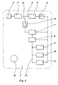
- Fig. 2
- die Schaltungskonfiguration eines zweiten Ausführungsbeispiels.
- Fig. 1
- 5 shows the circuit configuration of a contactless card of the type mentioned in a first embodiment of the arrangement of the switch system according to the invention, FIG.
- Fig. 2
- the circuit configuration of a second embodiment.
Gemäß dem ersten Ausführungsbeispiel (Fig. 1) besteht die Karte 1 aus einem (nicht dargestellten) Träger aus elektrisch isolierendem Material, in dem die folgende Schaltung integriert ist:According to the first embodiment (Fig. 1), the card 1 consists of a (not shown) carrier of electrically insulating material, in which the the following circuit is integrated:
Diese enthält zunächst eine Antenne 2, welche geeignet ist, hochfrequente
elektromagnetische Wellen zur Energie- und Informationsübertragung sowohl
zu empfangen als auch auszusenden. Diese Antenne 2 ist an ein Hochfrequenz-Interface
3 angeschlossen, welches u. a. eine Tuningschaltung (nicht
gezeichnet) enthält. Der Ausgang 17 des Hochfrequenz-Interfaces 3 ist über
ein betätigbares Schaltelement 16 auf eine Energieflußleitung 4 und auf eine
Informationsflußleitung 12 geführt.This first contains an
Unter dem Begriff Schaltelement sind dabei die -miniaturisierten- Wirkungselemente des Schaltersystems zur wahlweisen Unterbrechung des Energie- und des Informationssignals zu verstehen, die sowohl kontaktbehaftet als auch kontaktlos sein können.The term switching element are the miniaturized-effect elements the switch system for selectively interrupting the energy and to understand the information signal, both contact and can be contactless.
Die Energieflußleitung 4 führt über ein Spannungserzeugungssystem 5 in
Parallelschaltung auf einen Modulator/Demodulator 7 (der einen Analog-Digital-Wandler
enthält), auf eine Eingabe-/Ausgabe-Steuerschaltung 8, auf
eine Steuerung 9, auf einen Mikroprozessor 10 und auf eine oder mehrere
Speicherschaltungen 11. The
Die Informationsflußleitung 12 verbindet den Modulator/Demodulator 7 und die
nachgeschaltete Eingabe-/Ausgabe-Steuerschaltung 8. Dieser schließt sich ein
Bus 14 an für den informationsseitig parallelen Anschluß der Steuerung 9, des
Mikroprozessors 10 und der Speicherschaltungen 11.The
Das Schaltersystem ist über das Schaltelement 16 hinaus in der Zeichnung
nicht dargestellt. Es ist in einer ersten Variante durch einen von außen manuell
betätigbaren, miniaturisierten Schalter realisiert, dessen Schaltbereich (Feld
15) zwecks Sichtbarmachung auf der Oberfläche des Informationsträgers/der
Karte 1 farblich gekennzeichnet ist (Feld 15). In einer Vorzugsvariante beinhaltet
der Schalter Druckplättchen aus Quarzkristallen, die entsprechend dem
ersten Ausführungsbeispiel im Ausgang 17, in weiteren Varianten in die Antenne
und/oder Energie- und/oder Informationsflußleitungen integriert sind. Die
unter Druck (z. B. Fingerdruck) veränderte elektrische Leitfähigkeit der Quarzkristalle
bewirkt die Aktivierung des Schaltersystems.The switch system is beyond the
In weiteren Ausführungsvarianten des Schaltersystems sind statt dieses den Fingerdruck aufnehmenden Sensors Sensoren zur Erfassung eines Temperaturgradienten, einer Beschleunigung, der menschlichen Stimme bzw. eines Fingerabdruckes vorgesehen, wodurch das Schaltersystem aktivierbar ist. Eine weitere Ausführungsvariante beinhaltet Kombinationen von mehreren unterschiedlichen Aktivierungen, die gleichzeitig oder quasi gleichzeitig wirksam das Schaltersystem betätigen.In further embodiments of the switch system instead of this are the Finger pressure sensing sensor sensors for detecting a temperature gradient, an acceleration, the human voice or one Fingerprint provided, whereby the switch system can be activated. A Another embodiment includes combinations of several different ones Activations that take effect simultaneously or quasi simultaneously operate the switch system.
Die Wirkungsweise ist wie folgt:
Am Ausgang 17 des Hochfrequenz-Interfaces 3 liegt das empfangene Energieund
Informationssignal an. Es ist durch das Schaltelement 16 des Schaltersystems
wahlweise unterbrechbar, so daß weder der Energie- noch der Informationsanteil
des empfangenen Signals den Verarbeitungssystemen
(Modulator/Demodulator 7, Eingabe-/Ausgabe-Steuerschaltung 8, Steuerung
9, Mikroprozessor 10, Speicherschaltungen 11) zugeführt werden kann.At the
Bei aktiviertem Schaltelement 16 wird der Energieanteil des empfangenen Signals
über die Energieflußleitung 4 dem Spannungserzeugungssystem 5 zugeführt.
Die dort erzeugte elektrische Spannung versorgt über die Weiterführung
der Energieflußleitung 4 die Verarbeitungssysteme (7, 8, 9, 10, 11) mit elektrischer
Energie.When activated switching
Bei aktiviertem Schaltelement 16 wird weiterhin der Informationsanteil des
empfangenen Signals über die Informationsflußleitung 12 dem Modulator/Demodulator
7 zugeführt, der das Informationssignal demoduliert und digitalisiert.
Dieses Signal liegt nun über die Eingabe-/Ausgabe-Steuerschaltung 8
mit Hilfe des Busses 14 an der Steuerung 9 und an dem Mikroprozessor 10 an,
wobei die Informationen unter Verwendung der in den Speicherschaltungen 1
gespeicherten Anweisungen bzw. Programme und Daten verarbeitet, ggf. neu
gespeichert sowie - bei entsprechender Veranlassung durch die Eingabe-/Ausgabe-Steuerschaltung
8 - wieder dem Modulator/Demodulator 7 zwecks
Analogisierung und Modulierung und - sofern das Schaltelement 16 aktiviert ist
- über das Hochfrequenz-Interface 3 der Antenne 2 übertragen werden, wo
durch die Informationen über elektromagnetische Wellen wieder zum externen
Schreib-/Lesegerät gesendet werden.When the switching
Mit Hilfe des Schaltelementes 16 des Schaltersystems ist dabei durch den
Besitzer der Karte 1 bewußt und wahlweise sowohl die Energieversorgung der
Verarbeitungssysteme als auch der Informationsaustausch zwischen diesen
und der Antenne 2 der Karte 1 unterbrechbar, so daß weder eine Verarbeitung
ggf. von der Antenne 2 empfangener Informationen noch eine Veränderung
der Speicherinhalte noch eine Rücksendung von Informationen zu einem
Schreib-/Lesegerät möglich sind.With the help of the switching
Beim zweiten Ausführungsbeispiel (Fig. 2) ist das Hochfrequenz-Interface 3
ausgangsseitig unmittelbar auf die Energieflußleitung 4 sowie auf die Informationsflußleitung
12 geführt. Ein erstes betätigbares Schaltelement 6 des
Schaltersystems ist im Verlauf der Energieflußleitung 4 dem Spannungserzeugungssystem
5 nachgeschaltet, so daß die elektrische Versorgungsspannung
für die Verarbeitungssysteme wahlweise unterbrechbar ist.In the second embodiment (FIG. 2), the high-frequency interface is third
on the output side directly on the
Ein zweites betätigbares Schaltelement 13 des Schaltersystems ist in der Informationsflußleitung
12 angeordnet, um jeglichen Informationsaustausch zwischen
den Verarbeitungssystemen und der Antenne 2 wahlweise zu unterbrechen.A second
Da beide Schaltelemente 6, 13 durch das Schaltersystem gemeinsam betätigt
werden, erfolgt in entsprechender Weise die Unterbrechung sowohl des Energie-
als auch des Informationsanteils des empfangenen Signals, so daß eine
durch den Besitzer unbemerkte und/oder ungewollte Funktion der Karte 1 unmöglic
h ist.Since both switching
Im übrigen Aufbau entspricht das zweite dem ersten Ausführungsbeispiel mit entsprechender Wirkungsweise.In the rest of construction, the second corresponds to the first embodiment with corresponding mode of action.
Claims (4)
- Mobile, machine-readable information carrier, which without internal energy source cooperates without contact with the aid of high-frequency electromagnetic waves for the purpose of energy transmission and bidirectional information transmission with an external device, and which contains an antenna and a downstream interface, that on the output side by means of an energy flow line via a voltage generation system is connected to the processing systems as well as by means of an information flow line to the processing systems, which are designed as modulation/demodulations circuit, input/output control circuit, control system/processor, storage circuits, characterized in that
in the energy signal and information signal carrying output (17) of the antenna (2) or the downstream interface (3) a switch (16) is disposed or in the energy flow line (4) a switch (6) and in the information flow line (12) a switch (13) is disposed, whereby the switches (6, 13) in the energy flow line and information flow line can only be jointly actuated, as a result of which the information signal optionally is interruptible. - Mobile, machine-readable information carrier according to claim 1, characterized in that the switching system can be manually actuated from outside.
- Mobile, machine-readable information carrier according to claim 1, characterized in that the switching system (6, 13, 16) is activable by sensors reacting to temperature, motion, pressure or by acoustic sensors.
- Mobile, machine-readable information carrier according to claims 1 to 3, characterized in that the position of the switching system (6, 13, 16) is recognizable for the owner.
Applications Claiming Priority (2)
| Application Number | Priority Date | Filing Date | Title |
|---|---|---|---|
| DE19653409 | 1996-12-20 | ||
| DE19653409A DE19653409C2 (en) | 1996-12-20 | 1996-12-20 | Mobile, machine-readable information carrier |
Publications (3)
| Publication Number | Publication Date |
|---|---|
| EP0849703A2 EP0849703A2 (en) | 1998-06-24 |
| EP0849703A3 EP0849703A3 (en) | 1999-01-20 |
| EP0849703B1 true EP0849703B1 (en) | 2005-03-30 |
Family
ID=7815619
Family Applications (1)
| Application Number | Title | Priority Date | Filing Date |
|---|---|---|---|
| EP97122217A Expired - Lifetime EP0849703B1 (en) | 1996-12-20 | 1997-12-17 | Mobile information carrier readable by machine |
Country Status (2)
| Country | Link |
|---|---|
| EP (1) | EP0849703B1 (en) |
| DE (2) | DE19653409C2 (en) |
Cited By (1)
| Publication number | Priority date | Publication date | Assignee | Title |
|---|---|---|---|---|
| DE102014110694A1 (en) * | 2014-07-29 | 2016-02-04 | Bundesdruckerei Gmbh | Document with sensor means |
Families Citing this family (10)
| Publication number | Priority date | Publication date | Assignee | Title |
|---|---|---|---|---|
| DE19914587C2 (en) * | 1999-03-31 | 2001-05-03 | Orga Kartensysteme Gmbh | Smart card |
| DE10016716A1 (en) * | 2000-04-04 | 2001-08-02 | Infineon Technologies Ag | Dual interface data carrying card for contactless data transfer with user's confirmation - with contact surfaces contained in standardised contact field for user to place finger on to confirm wish to access card contents by contactless transfer |
| US7554383B2 (en) | 2001-03-02 | 2009-06-30 | Sony Corporation | Chip for non-contact reader/writer having power-supply management function |
| DE10221496A1 (en) * | 2002-05-14 | 2004-01-08 | Giesecke & Devrient Gmbh | Portable data carrier, esp. intelligent card e.g. as credit card or telephone card, has pressure-switch provided as perforation through data carrier adjacent to two terminals. |
| EP1760900B1 (en) * | 2004-06-10 | 2011-04-06 | Panasonic Corporation | Rfid tag and rfid tag communication distance modification method |
| DE102005036303A1 (en) * | 2005-04-29 | 2007-08-16 | Giesecke & Devrient Gmbh | Method for initializing and / or personalizing a portable data carrier |
| DE102006004805A1 (en) | 2006-01-24 | 2007-08-02 | Vodafone Holding Gmbh | Information carrier with means for contactless reading |
| EP1868140A1 (en) * | 2006-06-16 | 2007-12-19 | Assa Abloy Identification Technology Group AB | Contactless card with membrane switch made of an elasto-resistive material |
| WO2008092527A1 (en) * | 2007-01-31 | 2008-08-07 | International Business Machines Corporation | Deliberate access permission to data on contactless devices |
| JP5614335B2 (en) * | 2011-03-01 | 2014-10-29 | 株式会社リコー | RFID tag and electronic device equipped with RFID tag |
Citations (4)
| Publication number | Priority date | Publication date | Assignee | Title |
|---|---|---|---|---|
| US4582985A (en) * | 1981-03-18 | 1986-04-15 | Loefberg Bo | Data carrier |
| DE3928573A1 (en) * | 1988-08-31 | 1990-03-08 | Yamatake Honeywell Co Ltd | RADIO WAVE ANSWER DEVICE DEVICE IN AN ANSWER SYSTEM |
| DE4205556A1 (en) * | 1992-02-24 | 1993-08-26 | Angewandte Digital Elektronik | Smart electronic card with external switch control |
| EP0646983A2 (en) * | 1993-10-04 | 1995-04-05 | Amtech Corporation | Modulated backscatter microstrip patch antenna |
Family Cites Families (6)
| Publication number | Priority date | Publication date | Assignee | Title |
|---|---|---|---|---|
| DE3935364C1 (en) * | 1989-10-24 | 1990-08-23 | Angewandte Digital Elektronik Gmbh, 2051 Brunstorf, De | |
| US5274221A (en) * | 1990-06-22 | 1993-12-28 | Mitsubishi Denki Kabushiki Kaisha | Non-contact integrated circuit card |
| DE4205827C2 (en) * | 1992-02-26 | 1997-10-16 | Angewandte Digital Elektronik | Chip card for contactless, bidirectional transmission of energy and data with a read / write device |
| DE4319878A1 (en) * | 1992-06-17 | 1993-12-23 | Micron Technology Inc | High frequency identification system card - has integrated circuit chip or carrier layer sealed by top layer and coupled to batteries and antenna system |
| NL9301457A (en) * | 1993-08-23 | 1995-03-16 | Nedap Nv | Contactless identification card or smart card. |
| EP0676716A1 (en) * | 1994-03-07 | 1995-10-11 | Eric Bauer | Portable digital information carrier |
-
1996
- 1996-12-20 DE DE19653409A patent/DE19653409C2/en not_active Expired - Fee Related
-
1997
- 1997-12-17 DE DE59712254T patent/DE59712254D1/en not_active Expired - Lifetime
- 1997-12-17 EP EP97122217A patent/EP0849703B1/en not_active Expired - Lifetime
Patent Citations (4)
| Publication number | Priority date | Publication date | Assignee | Title |
|---|---|---|---|---|
| US4582985A (en) * | 1981-03-18 | 1986-04-15 | Loefberg Bo | Data carrier |
| DE3928573A1 (en) * | 1988-08-31 | 1990-03-08 | Yamatake Honeywell Co Ltd | RADIO WAVE ANSWER DEVICE DEVICE IN AN ANSWER SYSTEM |
| DE4205556A1 (en) * | 1992-02-24 | 1993-08-26 | Angewandte Digital Elektronik | Smart electronic card with external switch control |
| EP0646983A2 (en) * | 1993-10-04 | 1995-04-05 | Amtech Corporation | Modulated backscatter microstrip patch antenna |
Cited By (1)
| Publication number | Priority date | Publication date | Assignee | Title |
|---|---|---|---|---|
| DE102014110694A1 (en) * | 2014-07-29 | 2016-02-04 | Bundesdruckerei Gmbh | Document with sensor means |
Also Published As
| Publication number | Publication date |
|---|---|
| DE59712254D1 (en) | 2005-05-04 |
| EP0849703A3 (en) | 1999-01-20 |
| EP0849703A2 (en) | 1998-06-24 |
| DE19653409A1 (en) | 1998-07-02 |
| DE19653409C2 (en) | 2001-05-03 |
Similar Documents
| Publication | Publication Date | Title |
|---|---|---|
| EP1376460B1 (en) | Chip card | |
| EP0849703B1 (en) | Mobile information carrier readable by machine | |
| EP0502518B1 (en) | Wireless data transmission method on a data carrier | |
| DE4406704C1 (en) | Smart card | |
| DE602004005241T2 (en) | SECURITY DOCUMENT WITH A CONTACTLESS CHIP WITH DATA MASKING | |
| EP0424726A1 (en) | Chipcard | |
| EP0815530B1 (en) | Method and device for adapting a chip card to different card terminals | |
| DE69630843T2 (en) | System for the remote exchange of information between a portable passive object and a station, corresponding object and station | |
| EP1969533B1 (en) | Document comprising a data memory, device and method for reading an rfid tag, and computer program product | |
| EP0961960B1 (en) | Contactless log-on system for computers | |
| EP0867014A1 (en) | Chip card | |
| EP1969532A1 (en) | Document comprising an electronic appliance, device for accessing a data memory, and computer program product | |
| DE19629351A1 (en) | Mobile chip card reading module | |
| EP0557934B1 (en) | Chip card with external safety switch | |
| EP2774082B1 (en) | Reading device and adapter for a reading device | |
| WO2018161102A1 (en) | Deactivatable shielding element | |
| EP1072013A1 (en) | Chip card with an electronic blocking function | |
| EP1100045A1 (en) | Chipcard with contact interface and non-contact interface | |
| WO1997008929A2 (en) | Smart card with a chip, contact field, coils and/or capacitors and a storage element for galvanic or non-galvanic energy and data exchange with a read and/or write device | |
| EP2141637B1 (en) | Portable data carrier with active contactless interface and operating method | |
| DE3613150C2 (en) | ||
| DE102005049819B4 (en) | Transponder wireless keyboard and method of operating the same | |
| EP0370278A2 (en) | Method for activating chipcard reading apparatuses, and device for carrying out the method | |
| EP3593287A1 (en) | Deactivatable shielding element | |
| DE102005047048A1 (en) | Chip carrier access securing method for use in contactless data transmission system, involves eliminating reading of data as access protection by operating condition and establishing another condition by permanent magnet and foil |
Legal Events
| Date | Code | Title | Description |
|---|---|---|---|
| PUAI | Public reference made under article 153(3) epc to a published international application that has entered the european phase |
Free format text: ORIGINAL CODE: 0009012 |
|
| AK | Designated contracting states |
Kind code of ref document: A2 Designated state(s): DE FR GB |
|
| AX | Request for extension of the european patent |
Free format text: AL;LT;LV;MK;RO;SI |
|
| PUAL | Search report despatched |
Free format text: ORIGINAL CODE: 0009013 |
|
| RHK1 | Main classification (correction) |
Ipc: G06K 19/077 |
|
| AK | Designated contracting states |
Kind code of ref document: A3 Designated state(s): AT BE CH DE DK ES FI FR GB GR IE IT LI LU MC NL PT SE |
|
| AX | Request for extension of the european patent |
Free format text: AL;LT;LV;MK;RO;SI |
|
| 17P | Request for examination filed |
Effective date: 19990707 |
|
| AKX | Designation fees paid |
Free format text: DE FR GB |
|
| RAP1 | Party data changed (applicant data changed or rights of an application transferred) |
Owner name: GIESECKE & DEVRIENT GMBH |
|
| RIN1 | Information on inventor provided before grant (corrected) |
Inventor name: WEBER, CLAUDIA |
|
| 17Q | First examination report despatched |
Effective date: 20030603 |
|
| GRAP | Despatch of communication of intention to grant a patent |
Free format text: ORIGINAL CODE: EPIDOSNIGR1 |
|
| GRAS | Grant fee paid |
Free format text: ORIGINAL CODE: EPIDOSNIGR3 |
|
| GRAA | (expected) grant |
Free format text: ORIGINAL CODE: 0009210 |
|
| AK | Designated contracting states |
Kind code of ref document: B1 Designated state(s): DE FR GB |
|
| REG | Reference to a national code |
Ref country code: GB Ref legal event code: FG4D Free format text: NOT ENGLISH |
|
| REF | Corresponds to: |
Ref document number: 59712254 Country of ref document: DE Date of ref document: 20050504 Kind code of ref document: P |
|
| GBT | Gb: translation of ep patent filed (gb section 77(6)(a)/1977) |
Effective date: 20050421 |
|
| ET | Fr: translation filed | ||
| PLBE | No opposition filed within time limit |
Free format text: ORIGINAL CODE: 0009261 |
|
| STAA | Information on the status of an ep patent application or granted ep patent |
Free format text: STATUS: NO OPPOSITION FILED WITHIN TIME LIMIT |
|
| 26N | No opposition filed |
Effective date: 20060102 |
|
| PGFP | Annual fee paid to national office [announced via postgrant information from national office to epo] |
Ref country code: GB Payment date: 20121218 Year of fee payment: 16 |
|
| REG | Reference to a national code |
Ref country code: DE Ref legal event code: R082 Ref document number: 59712254 Country of ref document: DE |
|
| GBPC | Gb: european patent ceased through non-payment of renewal fee |
Effective date: 20131217 |
|
| PG25 | Lapsed in a contracting state [announced via postgrant information from national office to epo] |
Ref country code: GB Free format text: LAPSE BECAUSE OF NON-PAYMENT OF DUE FEES Effective date: 20131217 |
|
| PGFP | Annual fee paid to national office [announced via postgrant information from national office to epo] |
Ref country code: DE Payment date: 20141231 Year of fee payment: 18 |
|
| PGFP | Annual fee paid to national office [announced via postgrant information from national office to epo] |
Ref country code: FR Payment date: 20141212 Year of fee payment: 18 |
|
| REG | Reference to a national code |
Ref country code: DE Ref legal event code: R119 Ref document number: 59712254 Country of ref document: DE |
|
| REG | Reference to a national code |
Ref country code: FR Ref legal event code: ST Effective date: 20160831 |
|
| PG25 | Lapsed in a contracting state [announced via postgrant information from national office to epo] |
Ref country code: DE Free format text: LAPSE BECAUSE OF NON-PAYMENT OF DUE FEES Effective date: 20160701 |
|
| PG25 | Lapsed in a contracting state [announced via postgrant information from national office to epo] |
Ref country code: FR Free format text: LAPSE BECAUSE OF NON-PAYMENT OF DUE FEES Effective date: 20151231 |