EP0846859A2 - Engine ignition timing control system and method - Google Patents
Engine ignition timing control system and method Download PDFInfo
- Publication number
- EP0846859A2 EP0846859A2 EP98102223A EP98102223A EP0846859A2 EP 0846859 A2 EP0846859 A2 EP 0846859A2 EP 98102223 A EP98102223 A EP 98102223A EP 98102223 A EP98102223 A EP 98102223A EP 0846859 A2 EP0846859 A2 EP 0846859A2
- Authority
- EP
- European Patent Office
- Prior art keywords
- ignition timing
- engine
- valve motion
- motion condition
- condition data
- Prior art date
- Legal status (The legal status is an assumption and is not a legal conclusion. Google has not performed a legal analysis and makes no representation as to the accuracy of the status listed.)
- Granted
Links
Images


Classifications
-
- F—MECHANICAL ENGINEERING; LIGHTING; HEATING; WEAPONS; BLASTING
- F02—COMBUSTION ENGINES; HOT-GAS OR COMBUSTION-PRODUCT ENGINE PLANTS
- F02P—IGNITION, OTHER THAN COMPRESSION IGNITION, FOR INTERNAL-COMBUSTION ENGINES; TESTING OF IGNITION TIMING IN COMPRESSION-IGNITION ENGINES
- F02P3/00—Other installations
- F02P3/02—Other installations having inductive energy storage, e.g. arrangements of induction coils
- F02P3/04—Layout of circuits
- F02P3/045—Layout of circuits for control of the dwell or anti dwell time
- F02P3/0453—Opening or closing the primary coil circuit with semiconductor devices
- F02P3/0456—Opening or closing the primary coil circuit with semiconductor devices using digital techniques
-
- F—MECHANICAL ENGINEERING; LIGHTING; HEATING; WEAPONS; BLASTING
- F02—COMBUSTION ENGINES; HOT-GAS OR COMBUSTION-PRODUCT ENGINE PLANTS
- F02P—IGNITION, OTHER THAN COMPRESSION IGNITION, FOR INTERNAL-COMBUSTION ENGINES; TESTING OF IGNITION TIMING IN COMPRESSION-IGNITION ENGINES
- F02P5/00—Advancing or retarding ignition; Control therefor
- F02P5/04—Advancing or retarding ignition; Control therefor automatically, as a function of the working conditions of the engine or vehicle or of the atmospheric conditions
- F02P5/145—Advancing or retarding ignition; Control therefor automatically, as a function of the working conditions of the engine or vehicle or of the atmospheric conditions using electrical means
- F02P5/1455—Advancing or retarding ignition; Control therefor automatically, as a function of the working conditions of the engine or vehicle or of the atmospheric conditions using electrical means by using a second control of the closed loop type
-
- F—MECHANICAL ENGINEERING; LIGHTING; HEATING; WEAPONS; BLASTING
- F02—COMBUSTION ENGINES; HOT-GAS OR COMBUSTION-PRODUCT ENGINE PLANTS
- F02P—IGNITION, OTHER THAN COMPRESSION IGNITION, FOR INTERNAL-COMBUSTION ENGINES; TESTING OF IGNITION TIMING IN COMPRESSION-IGNITION ENGINES
- F02P5/00—Advancing or retarding ignition; Control therefor
- F02P5/04—Advancing or retarding ignition; Control therefor automatically, as a function of the working conditions of the engine or vehicle or of the atmospheric conditions
- F02P5/145—Advancing or retarding ignition; Control therefor automatically, as a function of the working conditions of the engine or vehicle or of the atmospheric conditions using electrical means
- F02P5/15—Digital data processing
- F02P5/1502—Digital data processing using one central computing unit
-
- Y—GENERAL TAGGING OF NEW TECHNOLOGICAL DEVELOPMENTS; GENERAL TAGGING OF CROSS-SECTIONAL TECHNOLOGIES SPANNING OVER SEVERAL SECTIONS OF THE IPC; TECHNICAL SUBJECTS COVERED BY FORMER USPC CROSS-REFERENCE ART COLLECTIONS [XRACs] AND DIGESTS
- Y02—TECHNOLOGIES OR APPLICATIONS FOR MITIGATION OR ADAPTATION AGAINST CLIMATE CHANGE
- Y02T—CLIMATE CHANGE MITIGATION TECHNOLOGIES RELATED TO TRANSPORTATION
- Y02T10/00—Road transport of goods or passengers
- Y02T10/10—Internal combustion engine [ICE] based vehicles
- Y02T10/40—Engine management systems
Definitions
- the present invention relates to engine ignition timing control system and method which are designed to utilize a speed density system for calculating the quantity of intake air in the combustion chamber of an internal combustion engine on the basis of pressure data in the intake manifold of the internal combustion engine and which have variable cylinder operation modes.
- the control system of the conventional internal combustion engine is so constructed that many operation data of the engine are gathered by many sensors for calculating predetermined control values in response to the operation data with suitable calculating means so that many actuators are driven by output signals responsive to the calculated control values to enable many mechanisms to be controllably driven in response to the predetermined control values.
- the quantity of intake air (A/N) to be supplied to the combustion chamber is adjusted in response to the opening of a throttle valve, and the quantity of fuel corresponding to the quantity of intake air in response to the opening of the throttle valve and the revolution of the engine is supplied to the combustion chamber of the engine so as to perform an ignition process at an adequate ignition timing in response to the quantity of intake air and the revolution of the engine.
- a speed density system for calculating intake air quantity data for use in a fuel supply mechanism and advanced angle quantity data for use in ignition timing control on the basis of pressure levels of air in the intake manifold.
- the speed density system is advantageous in that a pressure sensor in provided in an air duct held in communication with the intake manifold to sense pressure levels of air in the intake manifold by way of the air duct instead of an airflow sensor provided in the intake manifold to directly sense the quantity of intake air in the intake manifold, resulting in reducing the intake air resistance of the intake manifold and thus in decreasing costs of the sensors.
- the internal combustion engine having such a speed density system is operated in such a manner that a map is prepared for a standard ignition timing ⁇ b in response to an intake manifold pressure Pb in place of an intake air quantity A/N and an engine revolution Ne upon calculation of the ignition timing of the engine.
- the standard ignition timing ⁇ b is initially calculated in response to the engine revolution Ne and the intake manifold pressure Pb, and then compensated on the basis of coolant temperature Twt, intake air temperature Ta and the like for the purpose of calculating a target ignition timing ⁇ adv.
- the intake manifold pressure including the intake air quantity data is sensed for calculation of the intake air quantity and the ignition timing of the engine so that the operation mode variation of each of the cylinders of the engine such as, for example, the variation of the valve opening and closing timing caused by high and low cams of the intake and exhaust mechanism, and the variation of the intake air quantity caused by switching all cylinders worked conditions and partial cylinders worked conditions in which the intake and exhaust mechanisms of the cylinders are partially held in their unworked condition.
- An ignition timing control system for an internal combustion engine comprises engine revolution speed detecting means for detecting engine revolution speed of an engine to produce an output signal of engine revolution speed data of the engine, valve motion condition determining means for determining valve motion condition data of the engine to produce an output signal of the valve motion condition data for each of cylinders assembled in the engine, intake air pressure detecting means for detecting intake air pressure of air to be introduced into an intake manifold to produce an output signal of pressure data of the intake manifold, standard ignition timing calculating means for preparing a plurality of standard ignition timing calculating maps each of which shows the air pressure data of air in the intake manifold to the valve motion condition data and selecting one of the standard ignition timing maps in response to the valve motion condition data to calculate a standard ignition timing of each of the cylinders, target ignition timing calculating means for calculating for each of the cylinders a target ignition timing by compensating
- said operation mode variation determining means includes means for calculating the lapse of time from the variation of the valve motion data.
- said standard ignition timing calculating means includes operation mode variation determining means for determining variation of said valve motion condition data on the basis of said valve motion condition data inputted from said valve motion condition determining means, and calculates for each of the cylinders a standard ignition timing derived from the standard ignition timing calculated at the first time and the standard ignition timing calculated at the second time when variation of the valve motion condition data is determined after a predetermined time lapses from the first time.
- said operation mode variation determining means includes means for calculating the lapse of time from the variation of said valve motion condition data.
- All ignition timing control method for an internal combustion engine comprises the steps of:
- the operation mode determination includes calculating the lapse of time from the variation of the valve motion condition data.
- the standard ignition timing calculation includes determining the variation of said valve motion condition data on the basis of said valve motion condition data inputted from said valve motion condition determining means, and calculation for each of the cylinders a standard ignition timing derived from the standard ignition timing calculated at the first time and the standard ignition timing calculated at the second time when the variation of the valve motion condition data is determined after a predetermined time lapses from the first time.
- the operation mode variation determination includes calculating the lapse of time from the variation of said valve motion condition data.
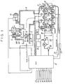
- An ignition timing control system is shown iN Fig. 1 as assembled in a four cylinders, in-line engine (simply referred to as "engine E") having a mechanism for switching and varying valve motion conditions of intake and exhaust valves.
- the engine E comprises an intake manifold 1 which is constituted by an intake branched duct 6, a surge tank 9 securely connected to the intake branched duct 6, an intake duct 7 integrally formed with the surge tank 9, and an air cleaner not shown.
- the intake duct 7 is adapted to rotatably receive therein a throttle valve 2 having a rotational shaft 201 connected to a throttle lever 3 at the outer side of the intake manifold 1.
- the throttle lever 3 is connected to and rotated by an accelerator pedal (not shown) in such a manner that the throttle valve 2 is rotated in clockwise and anti-clockwise directions as shown in Fig. 1 by the throttle lever 3.
- the throttle valve 2 is forced to be closed by a suitable return spring (not shown) when the accelerator pedal is released to its home position.
- the throttle valve 2 is assembled with a throttle valve opening sensor 8 for producing an output signal of the opening data of the throttle valve 2.
- an intake bypass duct 101 is connected to the intake duct 7 in such a manner as to bypass the throttle valve 2 and is provided with an idle revolution control (ISC) valve 4 forced to be closed by a return spring 401 and driven by a stepping motor 5.
- ISC idle revolution control
- the reference numeral 16 designates a first idle air valve which is designed to automatically perform a warming-up compensation in response to temperature of a coolant in the engine during the idling state of the engine.
- the intake air temperature detecting means comprises an intake air temperature sensor 14 provided in the intake manifold 1 for producing an output signal of the data for intake air temperature (Ta).
- the engine is provided with a coolant sensor 11 for detecting the temperature of the coolant therein.
- the engine revolution speed detecting means comprises an engine revolution sensor 12 for detecting the engine revolution in the form of ignition pulses.
- the battery voltage detecting means comprises a battery sensor 27 for detecting a battery voltage VB.
- a knock sensor 21 is also provided for producing an output signal of knock data of the engine.
- the intake air pressure detecting means comprises a vacuum sensor 10 provided in the surge tank 9 for producing an intake manifold pressure (Pb) data.
- a cylinder head 13 forming in part the engine is provided with intake and exhaust passageways capable of being in communication with each of cylinders formed in the engine and opened and closed respectively by intake and exhaust valves (not shown) forming as a whole a valve motion system.
- the valve motion system is designed to be operatable under a low speed mode M-1 and a high speed mode M-2 by selectively driving low and high speed cams, respectively, while being operable under an unwork partial cylinders mode (modulated displacement mode) M-3 by holding the intake and exhaust valves of a first cylinder #1 and a fourth cylinder in their unworked conditions, respectively, with a second cylinder #2 and a third cylinder #3 being held in their worked conditions, respectively.
- the valve motion system comprises rocker arms assembled with low and high speed mode switching mechanism K1 and K2, the former of which is designed to hydraulically held the low speed cams of the intake and exhaust valves under their worked conditions at a predetermined low speed mode, and the latter of which is similarly designed to hydraulically hold the high speed cams of the intake and exhaust valves under their worked conditions at a predetermined high speed mode.
- the low and high speed mode switching mechanisms K1 and K2 are well known in the art and so constructed as to have the low and high speed cams and the rocker arms selectively engaged with and disengaged from each other by hydraulically switching the engagement and disengagement conditions between the rocker arms and their rocker arm shafts by way of respective slide pins not shown.
- the low speed mode switching mechanism K1 forming a valve motion condition switching mechanism is fed with pressure oil by a pressure oil circuit 22 through a first electromagnet valve 26, while the high speed mode switching mechanism K2 also forming the valve motion condition switching mechanism is fed with pressure oil by a pressure oil circuit 30 through a second electromagnet valve 31. It will be understood that both of the first electromagnet valve 26 and the second electromagnet valve 31 respectively having three-way constructions are not energized under the low speed mode M-1 of the valve motion system, while both of the first electromagnet valve 26 and the second electromagnet valve 31 are energized under the high speed mode M-2 of the valve motion system.
- the first electromagnet valve 26 is energized, while the second electromagnet valve 31 in not energized under the unworked partial cylinders mode M-3 of the valve motion system.
- the above electromagnet valves 26 and 31 are controlled by the output driving signal of an engine control unit (ECU) 15 which will be described hereinafter.
- ECU engine control unit
- the cylinder head 13 is shown in Fig. 1 as provided with injectors 17 for injecting fuel to the cylinders, respectively, in such a manner that the injectors 17 are supplied from an fuel supply source 19 with fuel adjusted under a predetermined pressure level by a fuel pressure adjusting means 18.
- the injection control is carried out by the engine control unit 15 mentioned above.
- the cylinder head 13 is assembled with ignition plugs 23 for the respective cylinders under the condition that the ignition plugs 23 of the cylinders #2 and #3 always held under their worked conditions are electrically connected to an ignitor 24 provided in a single ignition driving circuit and that the ignition plugs 23 of the cylinders #1 and #4 held under their worked and unworked conditions are connected to electrically connected to an ignitor 25 provided in another single ignition driving circuit. Both of the ignitors 24 and 25 are electrically connected to the engine control unit 15.
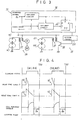
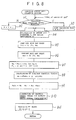
- the ignition driving circuit comprises a pair of timing control circuit 36 provided in the engine control unit 15 and a pair of driving circuits 241 and 251 for the respective ignitors 24 and 25. Only one of the control ciruit 36 is shown in Fig. 3. To the driving circuit 241 and 251 are electrically connected respectively power transistors 38 and 38 which are adapted to control opening and closing timing and energization time thereto and which are electrically connected to ignition coils 37 and 37.
- the timing control circuits 36 are respectively associated with the unworkable cylinders #1 and #4 capable of being held under their unworked conditions and the work cylinders #2 and #3 always held under their worked conditions in such a manner that the cylinders #1 to #4 are driven by standard signals ( ⁇ o of a crank angle) of crank angle sensors 34 and crank angle signals (1° or 2° ( ⁇ ) of a unit pulse) of unit crank angle sensors 33.
- the unworkable cylinders #1 and #4 are shown in Fig. 3, but the work cylinders #2 and #3 are not shown.
- the standard signal ⁇ o is outputted to a one-shot circuit B so that the one-shot circuit B is triggered by the standard signal (on-off) of upper dead point ⁇ o (for example 75°) and the energization commencement signal is outputted and counts a predetermined delay time t1 after crank angle signals (a unit pulse 1° or 2°) are produced as best shown in Fig. 4.
- a target ignition timing ⁇ b is calculated from the step b9 of a flowchart as will be described in Fig. 8.
- the one-shot circuit A is similarly triggered by the standard signal (on-off) and counts a delay time t1 and a predetermined number (delay time t2) of the crank signal corresponding to the dwell angle so as to produce ignition signals.
- a flip-flop F ⁇ F is set by the energization commencement signal of the one-shot circuit B and reset by the ignition signal of the one-shot circuit A.
- the opening and closing driving circuit 251 causes the power transistor 38 to be held “ON” during a period of time of the flip-flop F ⁇ F being set so as to maintain the ignition coil 37 energized.
- the ignition coil 37 causes its secondary side to have a high voltage current when the power transistor 38 is switched “OFF” so that the high voltage current is transmitted to and ignites the ignition plugs 23 of the unworkable cylinders #1 and #4 held in their unworked conditions.
- the timing control circuit (not shown) for the work cylinders #2 and #3 is constructed in a similar manner as the timing control circuit for the unworkable cylinders #1 and #4.
- the secondary high voltage current of the ignition coil 37 is supplied to and ignites the work cylinders #2 and #3 at their target ignition timing ⁇ b.
- the groups of the unworkable cylinders #1, #4 and the work cylinders #2 and #3 are alternately ignited at an interval, i.e., a crank angle of 180° degrees.
- the essential part of the engine control unit 15 is constituted by a micro-computer to perform the valve motion condition switching control and the ignition timing control in addition to the fuel injection control of the engine 1 and the throttle valve driving control which are well known in the art.
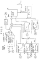
- the engine control unit 15 is shown in Fig. 2 as comprising an engine revolution sensor 12 for detecting the engine revolution speed Ne and a vacuum sensor 10 for detecting the intake air pressure Pb.
- the engine control unit 15 further comprises valve motion condition determining means for determining driving signals of first and second electromagnet valves 26 and 31 to produce output signals of the valve motion condition data for the respective cylinders held in their worked and unworked conditions.
- the engine control unit 15 further comprises standard ignition timing calculating means for calculating the standard ignition timing ⁇ b in response to the intake air pressure Pb and the engine revolution speed Ne on the basis of the valve motion condition data of each of the cylinders.
- the engine control unit 15 further comprises a coolant sensor for detecting a coolant Tw, a throttle valve opening sensor 8 for detecting a throttle opening ⁇ s, an intake air temperature sensor 14 for detecting intake air temperature Ta, a battery sensor 27 for detecting battery voltage VB, and a knock sensor 21 for detecting a knock signal Kn.
- the ignition timing calculating means thus constructed calculates a target ignition timing ⁇ adv by compensating the standard ignition timing ⁇ b on the basis of the operation data of the internal combustion engine.
- the main switch not shown is switched "ON" to commence the control of the engine control unit 15 along its main routine.
- a fuel cut zone is determined from an operation map calculating the operation zone on the basis of the engine revolution N and A/N as load data of the engine to have the operation advance to a step a3, where the air fuel ratio feedback FLG is cleared and returned with the fuel cut FLG "1" at a step a4.
- the fuel cut FLG is cleared, and whether or not the air fuel ratio feedback condition is met is then determined.
- the calculations are carried out on the air fuel ratio compensation coefficient KMAP responsive to the present operation data (A/N, N) and the idling operation increase quantity compensation coefficient Ka responsive to the coolant temperature Tw through a proper idling operation increase quantity compensation coefficient calculating map.
- the calculated values are stored in the address KAF and the operation is then progressed to a step a10.
- a target air fuel ratio responsive to the present operation data (A/N, N) is calculated for calculation of fuel quantity compensation coefficient K FB which can fulfil the above air fuel ratio.
- the fuel coefficient K FB is stored in the address KAF to have the operation advance to the step a10.
- the other fuel injection pulse width compensation coefficient KDT and the dead time compensation value TD of the fuel injection valve are set responsive to the operation condition of the engine to calculate each of compensation coefficients for use in the calculation of the target ignition timing ⁇ adv.
- the compensation values thus calculated comprises a coolant compensation value ⁇ wt varied in response to the temperature drop of the coolant, an acceleration retard ⁇ acc corresponding to the differential value ⁇ s obtained by differentiating the throttle valve opening ⁇ s, an intake air temperature compensating value ⁇ at varied in response to the temperature drop of the intake air, and a knock retard value ⁇ k increased in response to the knock signal Kn.
- the subsequent calculation is performed on the battery compensation value tb with its energization time period to be increased in response to the drop of the battery voltage VB.
- the operation advances to the step all where the other well known controls are performed and is then returned to the initial step.
- the ignition timing calculating routine is executed.
- the valve operation condition determining means 20 serves as determining and selecting any one of low and high speed modes M-1, M-2 and the unworked partial cylinders mode M-3 in response to the "ON" and "OFF" data of the first and second electromagnets 26 and 31.
- the operation mode variation determining means determines whether or not the present operation mode is identical to the previous operation mode. In the case of the operation mode being varied, the operation advances to a step b3, while in the case of the operation mode being not varied the operation advances to a step b2.
- the operation mode variation determining means may include a function as the valve motion condition determining means.
- the engine revolution Ne is detected by the engine revolution sensor 12 and the intake air pressure Pb is detected by the vacuum sensor 10.
- the previous operation mode is determined as being in the low speed operation mode M-1, or the high speed operation mode M-2, or the unworked partial cylinders mode M-3, and the standard ignition timing ⁇ b1 of the previous operation mode is calculated by the standard ignition timing maps m1, m2 and m3 as seen from Fig. 2.
- the low speed operation map m1 is employed for the low speed operation mode M-1 in the previous operation
- the high speed operation map m2 is employed for the high speed operation mode in the previous operation
- the unworked partial cylinders operation map m3 is employed for the unwork cylinder operation mode M-3 in the previous operation.
- the present operation mode is determined as being in the low speed operation mode M-1, or the high speed operation mode M-2, or the unworked partial cylinders mode M-3, and the standard ignition timing ⁇ b2 of the present operation mode is calculated by the standard ignition timing calculating maps m1, m2 and m3 in a similar fashion as shown in Fig. 2.
- the standard ignition timing ⁇ b is calculated in the following equation (3) by leveling the previous standard ignition timing ⁇ b1 and the present standard ignition timing ⁇ b2.
- a leveling coefficient an is initially calculated in the following equations (1) and (2).
- the leveling coefficients an are calculated respectively by the equation (1) when the time T after the variation of the operation mode is lower than the predetermined value n and by the equation (2) when the time T after the variation of the operation mode is higher than the predetermined value n.
- ⁇ a represents a leveling ratio which is for example set at about 0.1.
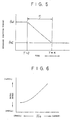
- Fig. 5 One example of the time progress variation characteristic of the standard ignition timing ⁇ b thus calculated as above is shown in Fig. 5. It will be understood from Fig. 5 that the previous standard ignition timing ⁇ b1 is corrected to progressively approach the present standard ignition timing ⁇ b2 in response to the leveling ratio ⁇ a. The above mentioned treatment results in the fact that the standard ignition timing ⁇ b which is not precisely recognized upon the operation mode variation is corrected and compensated, thereby preventing the excessive deviation from the desirable ignition timing of each of the cylinders.
- the acceleration retard ⁇ acc is calculated for calculating the target ignition timing ⁇ adv by the following equation (4).
- ⁇ adv ⁇ b + ⁇ wt + ⁇ at - ⁇ acc
- a predetermined retard quantity is calculated in response to the knock signal Kn by a suitable map not shown to correct the target ignition timing ⁇ adv toward the retard side.
- the knock retard map is previously established as shown in Fig. 2.
- the present ignition timing ⁇ advn is stored in the previous ignition timing area ⁇ adb (n-1) and the present leveling coefficient an is stored in the previous leveling coefficient area ⁇ (n-1) , then returning the operation to the main routine.
- the ignition control routine is executed on the basis of the fact that the standard signal ⁇ o is varied from “OFF” to "ON” when each of the cylinders are at every upper dead point 75° (75°BTDC) (a crank angle of 180 degrees) on the halfway of the main routine.
- a predetermined data is detected and at the step C2 whether the commencement switch not shown "ON” or "OFF” is determined.
- the operation advances to the steps C3 and C4 upon its initial stage, while the operation advances to the steps C5 and C6 upon its non-initial stage.
- the fixed ignition timing for example BTDC5°
- the dwell angle upon their initial stages are respectively set and returned to the main routine.
- the operation advances to the steps C5 and C6 upon its non-initial stage, the newest target ignition timing ⁇ t and the dwell angle calculated from Fig. 6 are set to the timing control circuit 36 and returned to the main routine.
- the worked cylinders #2 and #3 are simultaneously ignited by the ignitor 24 while the unworkable cylinders #1 and #4 are simultaneously ignited by the ignitor 25.
- those ignitors 24 and 25 are driven at every crank angle of 180 degrees, one and the other groups of the worked and unworkable cylinders #2, #3, #1 and #4 are alternately ignited at the vicinity of their compression upper dead point of the cylinder and at the vicinity of their exhaust dead point of the cylinder.
- the injector driving treatment is performed on the halfway of the main routine.
- the intake air quantity A/N calculated is detected in response to the intake air pressure Pb and the engine revolution Ne to calculate the standard fuel pulse width Tf.
- the target injector driving time is calculated by the air fuel ratio compensation coefficient KAF detected from the main routine, the compensation coefficient KDT of the atmospheric temperature and pressure, the injector action delay compensation value TD and the like.
- the target fuel pulse widths Tinj are set to the drivers of all the injectors 17 of the cylinders #1-#4, while during the operations of the cylinders #1 and #4 held in their unworked conditions the target fuel pulse widths Tinj are set to the drivers 17 of the cylinders #2 and #3 so as to trigger the drivers and to return the operation to the main routine.
- the present invention is advantageous in that the ignition timing can be performed for each of the cylinders of the internal combustion in response to the operation mode of the engine by detecting the engine revolution speed data and the intake manifold data by many sensors, determining the valve motion condition data, calculating the standard ignition timing in response to the valve motion condition data on the basis of the intake manifold pressure data and the engine revolution speed, and compensating the ignition timing of each of the cylinders to calculate the target ignition timing, resulting in the desirable ignition timing for each of the cylinders even in the speed density system.
Landscapes
- Engineering & Computer Science (AREA)
- Chemical & Material Sciences (AREA)
- Combustion & Propulsion (AREA)
- Mechanical Engineering (AREA)
- General Engineering & Computer Science (AREA)
- Theoretical Computer Science (AREA)
- Signal Processing (AREA)
- Electrical Control Of Ignition Timing (AREA)
- Output Control And Ontrol Of Special Type Engine (AREA)
- Electrical Control Of Air Or Fuel Supplied To Internal-Combustion Engine (AREA)
Abstract
Description
Claims (8)
- A system for controlling ignition timing for an internal combustion engine comprising:engine revolution speed detecting means for detecting engine revolution speed of an engine to produce an output signal of engine revolution speed data of the engine;valve motion condition determining means for determining valve motion condition data of the engine to produce an output signal of the valve motion condition data for each of cylinders assembled in the engine;intake air pressure detecting means for detecting intake air pressure of air to be introduced into an intake manifold to produce an output signal of pressure data of the intake manifold;standard ignition timing calculating means for preparing a plurality of standard ignition timing calculating maps each of which shows said air pressure data of air in the intake manifold and said engine revolution speed data varied in response to the valve motion condition data and selecting one of said standard ignition timing maps in response to said valve motion condition data to calculate a standard ignition timing of each of the cylinders;target ignition timing calculating means for calculating for each of said cylinders a target ignition timing by compensating the standard ignition timing on the basis of the operating condition of said engine; andignition driving means for driving the ignitor associated with each of said cylinders of the engine at said target ignition timing, wherein said standard ignition timing calculating means includes operation mode variation determining means for determining variation of said valve motion condition data on the basis of said valve motion condition data inputted from said valve motion condition determining means, and calculates for each of the cylinders a standard ignition timing on a smooth leveled line from the standard ignition timing calculated before the first time when the variation of the valve motion condition data is determined by said operation mode variation determining means to the standard ignition timing calculated after the second time when a predetermined time lapses after variation of the valve motion condition data is determined by said operation mode variation determining means.
- A system for controlling ignition timing for an internal combustion engine as set forth in Claim 1, wherein said operation mode variation determining means includes means for calculating the lapse of time from the variation of the valve motion condition data.
- A system for controlling ignition timing for an internal combustion engine as set forth in Claim 1, wherein said standard ignition timing calculating means includes operation mode variation determining means for determining variation of said valve motion condition data on the basis of said valve motion condition data inputted from said valve motion condition determining means, and calculates for each of the cylinders a standard ignition timing derived from the standard ignition timing calculated at the second time when the variation of the valve motion condition data is determined after a predetermined time lapses from the first time.
- A system for controlling ignition timing for an internal combustion engine as set forth in Claim 3, wherein said operation mode variation determining means includes means for calculating the lapse of time from the variation of said valve motion condition data.
- A method for controlling ignition timing for an internal combustion engine comprising the steps of:detecting engine revolution speed of an engine to produce an output signal of engine revolution speed data of the engine;determining valve motion condition data of the engine to produce an output signal of the valve motion condition data for each of cylinders assembled in the engine;detecting intake air pressure data of air to be introduced into the intake manifold to produce an output signal of air pressure data of the intake manifold;preparing a plurality of standard ignition timing calculating maps each of which shows said air pressure data of the intake manifold and said engine revolution speed data varied in response to valve motion condition data;selecting one of said standard ignition timing maps in response to said valve motion condition data and calculating a standard ignition timing of each of the cylinders;calculating for each of said cylinders a target ignition timing by compensating the standard ignition timing on the basis of the operating condition of the engine; anddriving an ignitor associated with each of said cylinders of the engine at said target ignition timing, wherein the standard ignition timing calculation includes determining variation of said valve motion condition data on the basis of valve motion condition data inputted from said valve motion condition determining means, and calculating for each of the cylinders a standard ignition timing on a smooth leveled line from the standard ignition timing calculated before the first time when the variation of the valve motion condition data is determined by said operation mode variation determining means to the standard ignition timing calculated after the second time when a predetermined time lapses after variation of the valve motion condition data is determined by said operation mode variation determining means.
- A method for controlling ignition timing for an internal combustion engine as set forth in Claim 5, wherein the operation mode variation determination includes calculating the lapse of time from the variation of the valve motion condition data.
- A method for controlling ignition timing for an internal combustion engine as set forth in Claim 6, wherein the standard ignition timing calculation includes determining variation of said valve motion condition data on the basis of said valve motion condition data inputted from said valve motion condition determining means, and calculating for each of the cylinders a standard ignition timing derived from the standard ignition timing calculated at the first time and the standard ignition timing calculated at the second time when the variation of the valve motion condition data is determined after a predetermined time lapses from the first time.
- A method for controlling ignition timing for an internal combustion engine as set forth in Claim 7, wherein the operation mode variation determination includes calculating the lapse of time from the variation of said valve motion condition data.
Applications Claiming Priority (4)
| Application Number | Priority Date | Filing Date | Title |
|---|---|---|---|
| JP4044004A JP2697458B2 (en) | 1992-02-28 | 1992-02-28 | Engine ignition timing control device |
| JP44004/92 | 1992-02-28 | ||
| JP4400492 | 1992-02-28 | ||
| EP93103090A EP0568780B1 (en) | 1992-02-28 | 1993-02-26 | Engine ignition timing control system and method |
Related Parent Applications (2)
| Application Number | Title | Priority Date | Filing Date |
|---|---|---|---|
| EP93103090A Division EP0568780B1 (en) | 1992-02-28 | 1993-02-26 | Engine ignition timing control system and method |
| EP93103090.2 Division | 1993-02-26 |
Publications (3)
| Publication Number | Publication Date |
|---|---|
| EP0846859A2 true EP0846859A2 (en) | 1998-06-10 |
| EP0846859A3 EP0846859A3 (en) | 1998-07-22 |
| EP0846859B1 EP0846859B1 (en) | 2005-12-07 |
Family
ID=12679563
Family Applications (2)
| Application Number | Title | Priority Date | Filing Date |
|---|---|---|---|
| EP98102223A Expired - Lifetime EP0846859B1 (en) | 1992-02-28 | 1993-02-26 | Engine ignition timing control system and method |
| EP93103090A Expired - Lifetime EP0568780B1 (en) | 1992-02-28 | 1993-02-26 | Engine ignition timing control system and method |
Family Applications After (1)
| Application Number | Title | Priority Date | Filing Date |
|---|---|---|---|
| EP93103090A Expired - Lifetime EP0568780B1 (en) | 1992-02-28 | 1993-02-26 | Engine ignition timing control system and method |
Country Status (6)
| Country | Link |
|---|---|
| US (1) | US5422811A (en) |
| EP (2) | EP0846859B1 (en) |
| JP (1) | JP2697458B2 (en) |
| KR (1) | KR970007393B1 (en) |
| AU (1) | AU665399B2 (en) |
| DE (2) | DE69324727T2 (en) |
Cited By (1)
| Publication number | Priority date | Publication date | Assignee | Title |
|---|---|---|---|---|
| WO2000049289A1 (en) * | 1999-02-16 | 2000-08-24 | Robert Bosch Gmbh | Ignition control device and method |
Families Citing this family (36)
| Publication number | Priority date | Publication date | Assignee | Title |
|---|---|---|---|---|
| JP2871408B2 (en) * | 1993-08-02 | 1999-03-17 | 日産自動車株式会社 | Internal combustion engine output control device |
| US5497745A (en) * | 1995-02-24 | 1996-03-12 | Ford Motor Company | Engine control for enhanced catalyst warm up while maintaining manifold vacuum |
| KR0174095B1 (en) * | 1995-07-21 | 1999-03-20 | 전성원 | Speed limit control method of automobile |
| DE19651238C2 (en) * | 1996-12-10 | 2001-06-21 | Bosch Gmbh Robert | Device determining the ignition angle of an internal combustion engine |
| EP0854273A1 (en) | 1997-01-21 | 1998-07-22 | Ford Global Technologies, Inc. | Variable valve timing and valve events mechanism for an internal combustion engine |
| JP2000130250A (en) | 1998-10-29 | 2000-05-09 | Kokusan Denki Co Ltd | Control device for internal combustion engine |
| JP2002180894A (en) * | 2000-12-12 | 2002-06-26 | Toyota Motor Corp | Controller of internal combustion engine |
| US6871617B1 (en) | 2004-01-09 | 2005-03-29 | Ford Global Technologies, Llc | Method of correcting valve timing in engine having electromechanical valve actuation |
| US7072758B2 (en) * | 2004-03-19 | 2006-07-04 | Ford Global Technologies, Llc | Method of torque control for an engine with valves that may be deactivated |
| US7017539B2 (en) * | 2004-03-19 | 2006-03-28 | Ford Global Technologies Llc | Engine breathing in an engine with mechanical and electromechanical valves |
| US7240663B2 (en) * | 2004-03-19 | 2007-07-10 | Ford Global Technologies, Llc | Internal combustion engine shut-down for engine having adjustable valves |
| US6938598B1 (en) | 2004-03-19 | 2005-09-06 | Ford Global Technologies, Llc | Starting an engine with electromechanical valves |
| US7555896B2 (en) * | 2004-03-19 | 2009-07-07 | Ford Global Technologies, Llc | Cylinder deactivation for an internal combustion engine |
| US7066121B2 (en) * | 2004-03-19 | 2006-06-27 | Ford Global Technologies, Llc | Cylinder and valve mode control for an engine with valves that may be deactivated |
| US7079935B2 (en) * | 2004-03-19 | 2006-07-18 | Ford Global Technologies, Llc | Valve control for an engine with electromechanically actuated valves |
| US7032581B2 (en) * | 2004-03-19 | 2006-04-25 | Ford Global Technologies, Llc | Engine air-fuel control for an engine with valves that may be deactivated |
| US7128687B2 (en) * | 2004-03-19 | 2006-10-31 | Ford Global Technologies, Llc | Electromechanically actuated valve control for an internal combustion engine |
| US7032545B2 (en) * | 2004-03-19 | 2006-04-25 | Ford Global Technologies, Llc | Multi-stroke cylinder operation in an internal combustion engine |
| US7165391B2 (en) * | 2004-03-19 | 2007-01-23 | Ford Global Technologies, Llc | Method to reduce engine emissions for an engine capable of multi-stroke operation and having a catalyst |
| US7107947B2 (en) * | 2004-03-19 | 2006-09-19 | Ford Global Technologies, Llc | Multi-stroke cylinder operation in an internal combustion engine |
| US7055483B2 (en) * | 2004-03-19 | 2006-06-06 | Ford Global Technologies, Llc | Quick starting engine with electromechanical valves |
| US7194993B2 (en) | 2004-03-19 | 2007-03-27 | Ford Global Technologies, Llc | Starting an engine with valves that may be deactivated |
| US7107946B2 (en) * | 2004-03-19 | 2006-09-19 | Ford Global Technologies, Llc | Electromechanically actuated valve control for an internal combustion engine |
| US7383820B2 (en) * | 2004-03-19 | 2008-06-10 | Ford Global Technologies, Llc | Electromechanical valve timing during a start |
| US7559309B2 (en) * | 2004-03-19 | 2009-07-14 | Ford Global Technologies, Llc | Method to start electromechanical valves on an internal combustion engine |
| US7063062B2 (en) * | 2004-03-19 | 2006-06-20 | Ford Global Technologies, Llc | Valve selection for an engine operating in a multi-stroke cylinder mode |
| US7128043B2 (en) | 2004-03-19 | 2006-10-31 | Ford Global Technologies, Llc | Electromechanically actuated valve control based on a vehicle electrical system |
| US7031821B2 (en) * | 2004-03-19 | 2006-04-18 | Ford Global Technologies, Llc | Electromagnetic valve control in an internal combustion engine with an asymmetric exhaust system design |
| US7028650B2 (en) * | 2004-03-19 | 2006-04-18 | Ford Global Technologies, Llc | Electromechanical valve operating conditions by control method |
| US7140355B2 (en) * | 2004-03-19 | 2006-11-28 | Ford Global Technologies, Llc | Valve control to reduce modal frequencies that may cause vibration |
| US7021289B2 (en) * | 2004-03-19 | 2006-04-04 | Ford Global Technology, Llc | Reducing engine emissions on an engine with electromechanical valves |
| JP4496162B2 (en) * | 2005-12-19 | 2010-07-07 | 日立オートモティブシステムズ株式会社 | Apparatus and method for controlling ignition timing of internal combustion engine |
| JP2009068388A (en) * | 2007-09-12 | 2009-04-02 | Honda Motor Co Ltd | Control device for internal combustion engine |
| KR101325501B1 (en) * | 2011-10-21 | 2013-11-07 | 주식회사 현대케피코 | Method for controlling ignition angle of bi-fuel vehicle |
| JP6088397B2 (en) * | 2013-10-15 | 2017-03-01 | 日本特殊陶業株式会社 | Ignition timing control device and ignition timing control system |
| JP6753288B2 (en) * | 2016-12-05 | 2020-09-09 | 株式会社デンソー | Ignition control system |
Citations (8)
| Publication number | Priority date | Publication date | Assignee | Title |
|---|---|---|---|---|
| DE3107666A1 (en) * | 1980-03-05 | 1982-02-25 | Robert Bosch Gmbh, 7000 Stuttgart | Device for controlling the ignition and/or fuel injection processes in internal combustion engines |
| US4398520A (en) * | 1980-04-03 | 1983-08-16 | Robert Bosch Gmbh | Ignition and fuel injection system for multicylinder engines |
| JPS59110858A (en) * | 1982-12-15 | 1984-06-26 | Mazda Motor Corp | Ignition timing control device for engine with its number of cylinders controlled |
| US4550704A (en) * | 1983-04-12 | 1985-11-05 | Robert Bosch Gmbh | Multi-cylinder internal combustion engine having disconnectable groups of cylinders |
| JPS6166843A (en) * | 1984-09-10 | 1986-04-05 | Mazda Motor Corp | Engine with valve timing controller |
| JPS6480736A (en) * | 1987-09-22 | 1989-03-27 | Honda Motor Co Ltd | Internal combustion engine |
| US4913116A (en) * | 1988-03-10 | 1990-04-03 | Hitachi, Ltd. | Ignition timing control apparatus for an internal combustion engine |
| JPH0385371A (en) * | 1989-08-28 | 1991-04-10 | Toyota Motor Corp | Ignition time controller for internal combustion engine |
Family Cites Families (16)
| Publication number | Priority date | Publication date | Assignee | Title |
|---|---|---|---|---|
| US4009695A (en) * | 1972-11-14 | 1977-03-01 | Ule Louis A | Programmed valve system for internal combustion engine |
| JPS5948307B2 (en) * | 1979-02-23 | 1984-11-26 | 日産自動車株式会社 | Internal combustion engine ignition timing control device |
| JPS5732069A (en) * | 1980-07-31 | 1982-02-20 | Nissan Motor Co Ltd | Igniter for internal combustion engine |
| JPS5746046A (en) * | 1980-09-04 | 1982-03-16 | Nissan Motor Co Ltd | Internal combustion engine-controller |
| US4502446A (en) * | 1981-12-10 | 1985-03-05 | Nissan Motor Company, Limited | Fail-safe system for automotive engine control system for fail-safe operation as crank angle sensor fails operation thereof and fail-safe method therefor, and detection of fault in crank angle sensor |
| DE3400786A1 (en) * | 1984-01-12 | 1985-07-18 | Robert Bosch Gmbh, 7000 Stuttgart | Ignition measuring device |
| JPH0680304B2 (en) * | 1984-05-07 | 1994-10-12 | トヨタ自動車株式会社 | Ignition timing control method for internal combustion engine |
| JPS6153419A (en) * | 1984-08-20 | 1986-03-17 | Toyota Motor Corp | Method of controlling intake in variable intake swirl system internal-combustion engine |
| JPS6296780A (en) * | 1985-10-22 | 1987-05-06 | Nissan Motor Co Ltd | Ignition timing control device |
| DE3601096A1 (en) * | 1986-01-16 | 1987-07-23 | Atlas Fahrzeugtechnik Gmbh | IGNITION SYSTEM FOR A COMBUSTION ENGINE |
| JPH07113356B2 (en) * | 1987-06-01 | 1995-12-06 | 日産自動車株式会社 | Ignition timing control device for internal combustion engine |
| JP2731905B2 (en) * | 1987-06-08 | 1998-03-25 | 富士重工業株式会社 | Ignition timing control method for internal combustion engine |
| US4945870A (en) * | 1988-07-29 | 1990-08-07 | Magnavox Government And Industrial Electronics Company | Vehicle management computer |
| JP2734060B2 (en) * | 1989-02-28 | 1998-03-30 | 三菱自動車工業株式会社 | Method of controlling intake air amount of internal combustion engine |
| JP2606440B2 (en) * | 1990-11-02 | 1997-05-07 | 三菱自動車工業株式会社 | Engine output control device |
| JPH05141336A (en) * | 1991-11-22 | 1993-06-08 | Honda Motor Co Ltd | Ignition device for internal combustion engine |
-
1992
- 1992-02-28 JP JP4044004A patent/JP2697458B2/en not_active Expired - Fee Related
-
1993
- 1993-02-25 US US08/022,490 patent/US5422811A/en not_active Expired - Fee Related
- 1993-02-26 EP EP98102223A patent/EP0846859B1/en not_active Expired - Lifetime
- 1993-02-26 DE DE69324727T patent/DE69324727T2/en not_active Expired - Fee Related
- 1993-02-26 AU AU33862/93A patent/AU665399B2/en not_active Ceased
- 1993-02-26 EP EP93103090A patent/EP0568780B1/en not_active Expired - Lifetime
- 1993-02-26 DE DE69333932T patent/DE69333932T2/en not_active Expired - Fee Related
- 1993-02-27 KR KR1019930002923A patent/KR970007393B1/en not_active IP Right Cessation
Patent Citations (8)
| Publication number | Priority date | Publication date | Assignee | Title |
|---|---|---|---|---|
| DE3107666A1 (en) * | 1980-03-05 | 1982-02-25 | Robert Bosch Gmbh, 7000 Stuttgart | Device for controlling the ignition and/or fuel injection processes in internal combustion engines |
| US4398520A (en) * | 1980-04-03 | 1983-08-16 | Robert Bosch Gmbh | Ignition and fuel injection system for multicylinder engines |
| JPS59110858A (en) * | 1982-12-15 | 1984-06-26 | Mazda Motor Corp | Ignition timing control device for engine with its number of cylinders controlled |
| US4550704A (en) * | 1983-04-12 | 1985-11-05 | Robert Bosch Gmbh | Multi-cylinder internal combustion engine having disconnectable groups of cylinders |
| JPS6166843A (en) * | 1984-09-10 | 1986-04-05 | Mazda Motor Corp | Engine with valve timing controller |
| JPS6480736A (en) * | 1987-09-22 | 1989-03-27 | Honda Motor Co Ltd | Internal combustion engine |
| US4913116A (en) * | 1988-03-10 | 1990-04-03 | Hitachi, Ltd. | Ignition timing control apparatus for an internal combustion engine |
| JPH0385371A (en) * | 1989-08-28 | 1991-04-10 | Toyota Motor Corp | Ignition time controller for internal combustion engine |
Non-Patent Citations (4)
| Title |
|---|
| PATENT ABSTRACTS OF JAPAN vol. 008, no. 230 (M-333), 23 October 1984 & JP 59 110858 A (MAZDA KK), 26 June 1984, * |
| PATENT ABSTRACTS OF JAPAN vol. 010, no. 234 (M-507), 14 August 1986 & JP 61 066843 A (MAZDA MOTOR CORP), 5 April 1986, * |
| PATENT ABSTRACTS OF JAPAN vol. 013, no. 287 (M-844), 30 June 1989 & JP 01 080736 A (HONDA MOTOR CO LTD), 27 March 1989, * |
| PATENT ABSTRACTS OF JAPAN vol. 015, no. 257 (M-1130), 28 June 1991 & JP 03 085371 A (TOYOTA MOTOR CORP), 10 April 1991, * |
Cited By (2)
| Publication number | Priority date | Publication date | Assignee | Title |
|---|---|---|---|---|
| WO2000049289A1 (en) * | 1999-02-16 | 2000-08-24 | Robert Bosch Gmbh | Ignition control device and method |
| US6571783B1 (en) | 1999-02-16 | 2003-06-03 | Robert Bosch Gmbh | Ignition control device and method |
Also Published As
| Publication number | Publication date |
|---|---|
| DE69333932T2 (en) | 2006-06-29 |
| AU665399B2 (en) | 1996-01-04 |
| EP0568780A2 (en) | 1993-11-10 |
| EP0846859B1 (en) | 2005-12-07 |
| DE69333932D1 (en) | 2006-01-12 |
| DE69324727T2 (en) | 1999-09-09 |
| US5422811A (en) | 1995-06-06 |
| EP0568780A3 (en) | 1994-11-09 |
| DE69324727D1 (en) | 1999-06-10 |
| AU3386293A (en) | 1993-09-02 |
| KR930018151A (en) | 1993-09-21 |
| EP0846859A3 (en) | 1998-07-22 |
| JPH05240134A (en) | 1993-09-17 |
| JP2697458B2 (en) | 1998-01-14 |
| KR970007393B1 (en) | 1997-05-08 |
| EP0568780B1 (en) | 1999-05-06 |
Similar Documents
| Publication | Publication Date | Title |
|---|---|---|
| EP0846859B1 (en) | Engine ignition timing control system and method | |
| US5231962A (en) | Fuel injection control system with split fuel injection for diesel engine | |
| US7258099B2 (en) | Internal combustion engine control method | |
| US5337719A (en) | Engine control system and method | |
| US5590632A (en) | Apparatus for computing the amount of intake air in internal combustion engine | |
| US4887573A (en) | Ignition timing adjusting apparatus for internal combustion engine | |
| EP0302735B1 (en) | Control apparatus of an internal combustion engine | |
| CN109386388A (en) | The control device of internal combustion engine | |
| EP0615066B1 (en) | Controlling device for multi-cylinder internal combustion engine | |
| US5505176A (en) | Valve seating noise discriminating system for engine with variable valve operating system | |
| US11293372B1 (en) | Method and system for adjusting operation of a fuel injector | |
| JP3491019B2 (en) | Idle rotation learning control system for electronically controlled throttle internal combustion engine | |
| JP3114352B2 (en) | Air-fuel ratio control device for internal combustion engine | |
| JP2697530B2 (en) | Ignition control device for internal combustion engine with valve stop mechanism | |
| JP2697531B2 (en) | Ignition control device for internal combustion engine with valve stop mechanism | |
| JP2615569B2 (en) | Fuel injection amount control device for internal combustion engine | |
| JPS62225922A (en) | Apparatus for generating false temperature of engine for vehicle | |
| JPS62225730A (en) | A/n abnormal reduction preventing device for engine in tap | |
| JPS62228128A (en) | Apparatus for discriminating cylinder causing misfire in multicylinder engine | |
| JPH06185386A (en) | Starting injection control method | |
| JPH06117349A (en) | Control device of engine | |
| EP0992679A2 (en) | Improved time delay ignition circuit for an internal combustion engine | |
| JPH02115541A (en) | Fuel control device for engine | |
| JPS60230527A (en) | Variable compression-ratio type engine | |
| JPS62225738A (en) | Idle revolution speed controller for engine for vehicle |
Legal Events
| Date | Code | Title | Description |
|---|---|---|---|
| PUAI | Public reference made under article 153(3) epc to a published international application that has entered the european phase |
Free format text: ORIGINAL CODE: 0009012 |
|
| PUAL | Search report despatched |
Free format text: ORIGINAL CODE: 0009013 |
|
| AC | Divisional application: reference to earlier application |
Ref document number: 568780 Country of ref document: EP |
|
| AK | Designated contracting states |
Kind code of ref document: A2 Designated state(s): DE FR GB NL |
|
| AK | Designated contracting states |
Kind code of ref document: A3 Designated state(s): DE FR GB NL |
|
| 17P | Request for examination filed |
Effective date: 19990121 |
|
| 17Q | First examination report despatched |
Effective date: 20020424 |
|
| GRAP | Despatch of communication of intention to grant a patent |
Free format text: ORIGINAL CODE: EPIDOSNIGR1 |
|
| GRAS | Grant fee paid |
Free format text: ORIGINAL CODE: EPIDOSNIGR3 |
|
| GRAA | (expected) grant |
Free format text: ORIGINAL CODE: 0009210 |
|
| AC | Divisional application: reference to earlier application |
Ref document number: 0568780 Country of ref document: EP Kind code of ref document: P |
|
| AK | Designated contracting states |
Kind code of ref document: B1 Designated state(s): DE FR GB NL |
|
| REG | Reference to a national code |
Ref country code: GB Ref legal event code: FG4D |
|
| REF | Corresponds to: |
Ref document number: 69333932 Country of ref document: DE Date of ref document: 20060112 Kind code of ref document: P |
|
| ET | Fr: translation filed | ||
| PLBE | No opposition filed within time limit |
Free format text: ORIGINAL CODE: 0009261 |
|
| STAA | Information on the status of an ep patent application or granted ep patent |
Free format text: STATUS: NO OPPOSITION FILED WITHIN TIME LIMIT |
|
| 26N | No opposition filed |
Effective date: 20060908 |
|
| REG | Reference to a national code |
Ref country code: FR Ref legal event code: CA |
|
| PGFP | Annual fee paid to national office [announced via postgrant information from national office to epo] |
Ref country code: NL Payment date: 20090215 Year of fee payment: 17 Ref country code: DE Payment date: 20090219 Year of fee payment: 17 |
|
| PGFP | Annual fee paid to national office [announced via postgrant information from national office to epo] |
Ref country code: GB Payment date: 20090225 Year of fee payment: 17 |
|
| PGFP | Annual fee paid to national office [announced via postgrant information from national office to epo] |
Ref country code: FR Payment date: 20090213 Year of fee payment: 17 |
|
| REG | Reference to a national code |
Ref country code: NL Ref legal event code: V1 Effective date: 20100901 |
|
| GBPC | Gb: european patent ceased through non-payment of renewal fee |
Effective date: 20100226 |
|
| REG | Reference to a national code |
Ref country code: FR Ref legal event code: ST Effective date: 20101029 |
|
| PG25 | Lapsed in a contracting state [announced via postgrant information from national office to epo] |
Ref country code: NL Free format text: LAPSE BECAUSE OF NON-PAYMENT OF DUE FEES Effective date: 20100901 Ref country code: FR Free format text: LAPSE BECAUSE OF NON-PAYMENT OF DUE FEES Effective date: 20100301 |
|
| PG25 | Lapsed in a contracting state [announced via postgrant information from national office to epo] |
Ref country code: DE Free format text: LAPSE BECAUSE OF NON-PAYMENT OF DUE FEES Effective date: 20100901 |
|
| PG25 | Lapsed in a contracting state [announced via postgrant information from national office to epo] |
Ref country code: GB Free format text: LAPSE BECAUSE OF NON-PAYMENT OF DUE FEES Effective date: 20100226 |