EP0846429A2 - A chair structure - Google Patents

A chair structure Download PDF

Info

Publication number
EP0846429A2
EP0846429A2 EP97203375A EP97203375A EP0846429A2 EP 0846429 A2 EP0846429 A2 EP 0846429A2 EP 97203375 A EP97203375 A EP 97203375A EP 97203375 A EP97203375 A EP 97203375A EP 0846429 A2 EP0846429 A2 EP 0846429A2
Authority
EP
European Patent Office
Prior art keywords
structure according
chair structure
backrest
frame
slot
Prior art date
Legal status (The legal status is an assumption and is not a legal conclusion. Google has not performed a legal analysis and makes no representation as to the accuracy of the status listed.)
Withdrawn
Application number
EP97203375A
Other languages
German (de)
French (fr)
Other versions
EP0846429A3 (en
Inventor
Antonio Dal Monte
Current Assignee (The listed assignees may be inaccurate. Google has not performed a legal analysis and makes no representation or warranty as to the accuracy of the list.)
Clerprem SpA
Original Assignee
Clerprem SpA
Priority date (The priority date is an assumption and is not a legal conclusion. Google has not performed a legal analysis and makes no representation as to the accuracy of the date listed.)
Filing date
Publication date
Application filed by Clerprem SpA filed Critical Clerprem SpA
Publication of EP0846429A2 publication Critical patent/EP0846429A2/en
Publication of EP0846429A3 publication Critical patent/EP0846429A3/en
Withdrawn legal-status Critical Current

Links

Images

Classifications

    • AHUMAN NECESSITIES
    • A47FURNITURE; DOMESTIC ARTICLES OR APPLIANCES; COFFEE MILLS; SPICE MILLS; SUCTION CLEANERS IN GENERAL
    • A47CCHAIRS; SOFAS; BEDS
    • A47C7/00Parts, details, or accessories of chairs or stools
    • A47C7/36Support for the head or the back
    • A47C7/40Support for the head or the back for the back
    • AHUMAN NECESSITIES
    • A47FURNITURE; DOMESTIC ARTICLES OR APPLIANCES; COFFEE MILLS; SPICE MILLS; SUCTION CLEANERS IN GENERAL
    • A47CCHAIRS; SOFAS; BEDS
    • A47C1/00Chairs adapted for special purposes
    • A47C1/02Reclining or easy chairs
    • A47C1/022Reclining or easy chairs having independently-adjustable supporting parts
    • AHUMAN NECESSITIES
    • A47FURNITURE; DOMESTIC ARTICLES OR APPLIANCES; COFFEE MILLS; SPICE MILLS; SUCTION CLEANERS IN GENERAL
    • A47CCHAIRS; SOFAS; BEDS
    • A47C7/00Parts, details, or accessories of chairs or stools
    • A47C7/02Seat parts
    • A47C7/024Seat parts with double seats
    • AHUMAN NECESSITIES
    • A47FURNITURE; DOMESTIC ARTICLES OR APPLIANCES; COFFEE MILLS; SPICE MILLS; SUCTION CLEANERS IN GENERAL
    • A47CCHAIRS; SOFAS; BEDS
    • A47C7/00Parts, details, or accessories of chairs or stools
    • A47C7/36Support for the head or the back
    • A47C7/40Support for the head or the back for the back
    • A47C7/405Support for the head or the back for the back with double backrests

Definitions

  • the present invention relates in general to a chair structure for continuous use by the same person for prolonged sessions as is the case, for example, with chairs used in offices, laboratories, data-processing centres and similar so-called sedentary work-stations.
  • the problem upon which the present invention is based is that of providing a chair particularly for so-called sedentary work-stations, which has structural and functional characteristics such that, as well as satisfying all of the requirements set out above, it can be adapted quickly and easily ad personam, that is, it can be adapted to changed requirements of the same person, even within the same "session", all without in any way hindering the user's ability to work.
  • a chair according to the invention comprises a base 2 with wheels 3 which are orientable in some manner, a telescopically-extendable pillar 4 extending from centre of the base, means not shown since they are wholly conventional for adjusting the height of the pillar 4, a seat, generally indicated 5, supported by the pillar 4 and rotatable relative to the base 2, and a backrest 6 supported by a curved, resiliently yielding arm 7, with marked concavity facing towards the seat 5 with the rear of which it is associated in the manner which will be described further below.
  • the seat 5 in turn comprises a substantially box-like frame 8 for supporting a body 9, preferably made of a suitable resiliently-deformable material, for example and preferably, a plastics material such as nylon.
  • a pad/squab 10 is associated with the body 9, to which it is fixed in order substantially to form a single body with regard to "movements or displacements" and/or the deformations which the body 9 has to undergo (also limited to its parts) for the desired adjustments of the seat of the invention, as will become clear from the following description.
  • the body 9 is controlled by means for adjusting its fore-and-aft inclination to the horizontal.
  • the body 9 is mounted for pivoting on pins 11, 11 carried by opposite sides 8a, 8b of the box-like frame 8 and defining a horizontal articulation axis (with reference to the chair 1 in its condition of use), transverse the body.
  • a shaft 12 parallel to the articulation axis of the body is supported for rotating by the sides 8a, 8b of the frame 8 and two pinions 13, 13 are keyed to the shaft 12. These pinions 13, 13 are in engagement with respective racks 14, 15 slidable in guides 16, 17 fixed to or otherwise formed in the frame 8 and extending perpendicular to the shaft 12.
  • Respective vertical supports 18, 19 are fixed to the front portions of the racks and a respective idle wheel (or roller) 20, 21 is associated with the top of each support 18, 19 with its axis parallel to the articulation axis 11-11.
  • the wall of the body 9 facing the frame 8 defines, at the front, two straight ramps 22, 23 inclined downwardly towards the front of the body.
  • Each ramp 22, 23 is intended to be engaged by a corresponding idle wheel 20, 21 for which it constitutes essentially a straight cam profile.
  • the racks 14 and 15 and the wheels 20, 21 fixed thereto can be moved to and fro along the respective guides 16, 17 in the two directions towards the front and towards the rear of the seat 5.
  • the racks 14, 15 may be fixed to the frame 8 and the pinions 13, 13 and the shaft 12 to which they are keyed may be free to translate.
  • the shaft 12 will again be supported for rotation by the frame 8 with the formation of slit-like slots in the opposite sides 8a, 8b of the frame to allow the shaft 12 and the pinions 13-13 associated therewith to perform the desired rectilinear movements in opposite directions.
  • the idle wheels 20-21 (or rollers) in this case are fixed for rectilinear movement with the pinions 13-13.
  • the body 9 and the squab 10 are formed with an accentuated transverse concavity ( Figure 1) so as to achieve a marked "wrap-around” effect with consequent considerable lateral restraint.
  • the body 9 is controlled by means for gradually varying its transverse concavity.
  • a shaft 25a supported for rotation by opposite sides 8a, 8b of the frame 8 extends beneath the front portion of the body 9.
  • Two threaded portions 26, 27 with right-hand and left-hand threads formed on the shaft 25a in the region of the parts 9a, 9b of the front portion are engaged by respective threaded sleeves (or nuts) 28, 29 ( Figure 7).
  • a corresponding wedge 30, 31 fixed to each of the said sleeves 28, 29 extends transversely relative to the body 9 and has an upper active profile extending transversely relative to the body; the active profile matches and is engaged with the profile of the respective part 9a, 9b of the front body portion.
  • the wedges 30, 31 are moved towards one another or apart, that is, towards and away from the centre of the front body portion.
  • the parts 9a, 9b of the body are gradually raised with a consequent increase in the transverse concavity of the front portion.
  • a U-shaped slot 34 with sides extending towards the front of the seat is formed ( Figure 8) in the central rear region of the squab/pad 10 where, statistically, the bony "projections" of the user's pelvis and coccyx are supported.
  • the slot 34 also affects the underlying body 9 ( Figure 3).
  • this slot 34 substantially reduces the amount of pressure which is normally exerted on the aforesaid bony projections when chairs of the prior art are in use. This reduction results in a delay in the onset of a condition of restlessness (and often discomfort) which always arises when a fixed position is maintained for too long.
  • the presence of the slot 34 considerably improves ventilation in a region of the body which, as is well known, is characterized by the highest skin temperatures.
  • a further advantage of the slot 34 is of a static nature, since the lateral portions of the user's buttocks and thighs are "loaded", and a widened support base characterized by reduced pressure and in particular by an absence of excessive pressure peaks is created in these portions.
  • the arm 7 supporting the backrest 6 is preferably constituted by a resiliently-deformable metal strip which, in accordance with a non-limiting embodiment, comprises an arcuate central portion 7a with marked concavity, extended by a straight portion 7b and, at the other end, by a branched, Y-shaped end portion forming two identical wings 7c, 7d.
  • the straight portion 7b ( Figure 2) is engaged for sliding in an essentially sheath-like guide 35 defined in the frame 8 beneath the body 9 and extending longitudinally relative to the seat 5.
  • Means are provided for positioning the portion 7b adjustably along the respective guide 35 so that the backrest 6 can be moved away from or towards the seat 5 at will.
  • These means are wholly conventional and comprise, for example, one (or more) pins 36 fixed to the straight portion 7b and a plurality of holes 37 formed in the guide 35 and aligned along it at a predetermined pitch.
  • a grip 38 is provided for moving the backrest 6 along the axis defined by the guide 35 and is fixed to the arm 7, for example, in the region in which it branches into the two wings 7c, 7d ( Figure 9).
  • the backrest 6 is constituted by two identical, independent portions 39, 40 actuated independently by identical mechanisms so that they can be adapted to the user's back in the manner described below.
  • Each of the portions 39, 40 and the respective actuating mechanism are mounted on a respective wing 7c, 7d of the support 7, as will become clear from the following description relating to only one of them.
  • each wing 7c (7d) supports for rotation a shaft 41 to which a pinion 42 and an operating knob 43 (43a) are keyed in the front portion and in the rear portion of the backrest 6, respectively.
  • Two identical idle gears 44, 45 supported by the same wing 7c (7d) mesh with the pinion 42.
  • the idle gears 44, 45 have respective eccentric pins 46, 47 (crank pins) which extend from the same side and the axes of which, in a preferred but not exclusive embodiment, lie in the same horizontal plane.
  • the backrest portion 39, 40 in question is fixed to the eccentric pins 46, 47 and follows all of their movements (like a connecting rod).
  • each portion 39, 40 of the backrest 6 is constituted by two plate-like elements 39a, 39b ( Figure 11) connected to one another by means of a universal joint 48 (or ball joint or equivalent system), the element 39a being associated with the eccentric pins 46, 47, and the element 39b being intended to "cling" to the user's back.

Abstract

The chair structure described comprises a seat (5) and a backrest (6) which are adjustable independently of one another according to the desired conditions of support.

Description

The present invention relates in general to a chair structure for continuous use by the same person for prolonged sessions as is the case, for example, with chairs used in offices, laboratories, data-processing centres and similar so-called sedentary work-stations.
It is known that constant intensive research has been in progress for a long time by office furniture producers into the production of chairs for the aforesaid use having structural and functional characteristics such as to comply with and satisfy the various requirements for "comfortable" use thereof, these requirements arising from users' many and varied body sizes, from the different sizes of the body parts of people of the same height, from the different positions which users like to adopt on the said chairs even though they are often incorrect, and hence from the different "qualities" of comfort sought by users even when they are assigned to substantially the same jobs and tasks.
The most widely known results of the aforesaid research are limited to a relatively wide range of anatomical shapes attributed both to the seat and to the backrest, to the shapes and sizes of the padding/squabs, when these are provided, to the adjustability of the height of the seat and of the backrest, to mobility on wheels which are orientable in some manner, to a certain degree of springing, etc.
Moreover, it is known that the aforementioned characteristics of chairs of the prior art are not exhaustive with regard to the many and more important physical-anatomical requirements of users such as, for example, that of offering different load-carrying capacities for the various regions of the body so as to ensure maximum comfort and, in particular, to prevent undesirable excessive pressure in regions characterized by the presence of bony structures close to the skin surface and/or parts of the nervous system and/or of the vascular system, as well as muscular components, tendons, insertions and connective components, or that of providing effective transverse restraint for the vertebral column, particularly in the lumbar portion, which restraint should naturally be adaptable to users' different body structures.
Another important requirement which, up to now, has not been satisfied by the chairs of the prior art is that constituted by the need to prevent the formation of heat traps, that is, areas of the seat in which the heat emanating from the body is not correctly dissipated.
The problem upon which the present invention is based is that of providing a chair particularly for so-called sedentary work-stations, which has structural and functional characteristics such that, as well as satisfying all of the requirements set out above, it can be adapted quickly and easily ad personam, that is, it can be adapted to changed requirements of the same person, even within the same "session", all without in any way hindering the user's ability to work.
This problem is solved, according to the invention, by a chair structure formed in accordance with the following claims.
The characteristics and advantages of the invention will become clearer from the detailed description of an embodiment of the invention given below with reference to the appended drawings, provided by way of non-limiting example, in which:
  • Figure 1 is a schematic front view of a chair according to the invention,
  • Figure 2 is a longitudinal median section through the seat of the chair of Figure 1,
  • Figure 3 is a section taken on the line III-III of Figure 2,
  • Figure 4 is a section taken on the line IV-IV of Figure 2, on an enlarged scale,
  • Figure 5 is a section taken on the line V-V of Figure 2, on an enlarged scale,
  • Figure 6 is a section taken on the line VI-VI of Figure 2 on an enlarged scale,
  • Figure 7 is a schematic view of the seat of the chair of Figure 1 from below,
  • Figure 8 is a view of the chair seat of Figure 1 from above,
  • Figure 9 is a schematic view of the chair according to the invention from behind,
  • Figure 10 is a view of a detail of Figure 9, on an enlarged scale,
  • Figure 11 is a section taken on the line XI--XI of Figure 10.
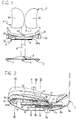
  • With reference to the drawings mentioned above, a chair according to the invention, generally indicated 1, comprises a base 2 with wheels 3 which are orientable in some manner, a telescopically-extendable pillar 4 extending from centre of the base, means not shown since they are wholly conventional for adjusting the height of the pillar 4, a seat, generally indicated 5, supported by the pillar 4 and rotatable relative to the base 2, and a backrest 6 supported by a curved, resiliently yielding arm 7, with marked concavity facing towards the seat 5 with the rear of which it is associated in the manner which will be described further below.
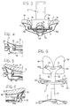
    The seat 5 in turn comprises a substantially box-like frame 8 for supporting a body 9, preferably made of a suitable resiliently-deformable material, for example and preferably, a plastics material such as nylon. A pad/squab 10 is associated with the body 9, to which it is fixed in order substantially to form a single body with regard to "movements or displacements" and/or the deformations which the body 9 has to undergo (also limited to its parts) for the desired adjustments of the seat of the invention, as will become clear from the following description.
    So that the rear surfaces of the user's thighs can be fully supported on the seat of the present invention irrespective of the height of the seat from the ground, the body 9 is controlled by means for adjusting its fore-and-aft inclination to the horizontal.
    In particular, on its side which extends close to the backrest 6, the body 9 is mounted for pivoting on pins 11, 11 carried by opposite sides 8a, 8b of the box-like frame 8 and defining a horizontal articulation axis (with reference to the chair 1 in its condition of use), transverse the body.
    A shaft 12 parallel to the articulation axis of the body is supported for rotating by the sides 8a, 8b of the frame 8 and two pinions 13, 13 are keyed to the shaft 12. These pinions 13, 13 are in engagement with respective racks 14, 15 slidable in guides 16, 17 fixed to or otherwise formed in the frame 8 and extending perpendicular to the shaft 12.
    Respective vertical supports 18, 19 are fixed to the front portions of the racks and a respective idle wheel (or roller) 20, 21 is associated with the top of each support 18, 19 with its axis parallel to the articulation axis 11-11.
    The wall of the body 9 facing the frame 8 defines, at the front, two straight ramps 22, 23 inclined downwardly towards the front of the body. Each ramp 22, 23 is intended to be engaged by a corresponding idle wheel 20, 21 for which it constitutes essentially a straight cam profile.
    If the shaft 12 is rotated, for example, by means of two knobs 24, 25 accessible outside the frame 8, the racks 14 and 15 and the wheels 20, 21 fixed thereto can be moved to and fro along the respective guides 16, 17 in the two directions towards the front and towards the rear of the seat 5.
    As a result of the engagement of the idle wheels with the respective cam profiles 22, 23, these movements bring about corresponding angular movements of the body 9 (in one direction and in the opposite direction) about its own articulation axis 11, 11.
    Naturally, a capability to vary the fore-and-aft inclination of the seat to the horizontal may be achieved by means other than those described but wholly equivalent thereto. Thus, for example, for particular constructional requirements or the like, the racks 14, 15 may be fixed to the frame 8 and the pinions 13, 13 and the shaft 12 to which they are keyed may be free to translate. The shaft 12 will again be supported for rotation by the frame 8 with the formation of slit-like slots in the opposite sides 8a, 8b of the frame to allow the shaft 12 and the pinions 13-13 associated therewith to perform the desired rectilinear movements in opposite directions. The idle wheels 20-21 (or rollers) in this case are fixed for rectilinear movement with the pinions 13-13.
    To prevent the backs of the knees from bearing on the front edge of the seat and hence to avoid compression of the peripheral vessels present in this region, the body 9 and the squab 10 are formed with an accentuated transverse concavity (Figure 1) so as to achieve a marked "wrap-around" effect with consequent considerable lateral restraint.
    In order to be able to vary the degree of this lateral restraint so as to adapt it in an optimal manner to the users' various personal requirements, the body 9 is controlled by means for gradually varying its transverse concavity.
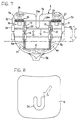
    For this purpose, the resilient deformability of a front portion of predetermined width of the body 9, which itself is already made of a suitable resiliently deformable material, is accentuated by the presence of a slot 24a extending axially throughout the width of this portion, in which two parts 9a, 9b are thus defined (Figure 7).
    A shaft 25a supported for rotation by opposite sides 8a, 8b of the frame 8 extends beneath the front portion of the body 9. Two threaded portions 26, 27 with right-hand and left-hand threads formed on the shaft 25a in the region of the parts 9a, 9b of the front portion are engaged by respective threaded sleeves (or nuts) 28, 29 (Figure 7).
    A corresponding wedge 30, 31 fixed to each of the said sleeves 28, 29 extends transversely relative to the body 9 and has an upper active profile extending transversely relative to the body; the active profile matches and is engaged with the profile of the respective part 9a, 9b of the front body portion.
    If the shaft 25 is rotated (in one direction or in the opposite direction) for example, by means of knobs 32, 33 associated therewith and accessible from outside the frame 8, the wedges 30, 31 are moved towards one another or apart, that is, towards and away from the centre of the front body portion. As a result of the movement of the wedges towards one another, the parts 9a, 9b of the body are gradually raised with a consequent increase in the transverse concavity of the front portion. When the wedges 30, 31 are moved apart, the said parts gradually "return resiliently" to the initial position.
    A U-shaped slot 34 with sides extending towards the front of the seat is formed (Figure 8) in the central rear region of the squab/pad 10 where, statistically, the bony "projections" of the user's pelvis and coccyx are supported.
    The slot 34 also affects the underlying body 9 (Figure 3).
    The presence of this slot 34 substantially reduces the amount of pressure which is normally exerted on the aforesaid bony projections when chairs of the prior art are in use. This reduction results in a delay in the onset of a condition of restlessness (and often discomfort) which always arises when a fixed position is maintained for too long.
    Moreover, the presence of the slot 34 considerably improves ventilation in a region of the body which, as is well known, is characterized by the highest skin temperatures.
    A further advantage of the slot 34 is of a static nature, since the lateral portions of the user's buttocks and thighs are "loaded", and a widened support base characterized by reduced pressure and in particular by an absence of excessive pressure peaks is created in these portions.
    With reference to Figures 1, 2 and 9, the arm 7 supporting the backrest 6 is preferably constituted by a resiliently-deformable metal strip which, in accordance with a non-limiting embodiment, comprises an arcuate central portion 7a with marked concavity, extended by a straight portion 7b and, at the other end, by a branched, Y-shaped end portion forming two identical wings 7c, 7d.
    The straight portion 7b (Figure 2) is engaged for sliding in an essentially sheath-like guide 35 defined in the frame 8 beneath the body 9 and extending longitudinally relative to the seat 5. Means are provided for positioning the portion 7b adjustably along the respective guide 35 so that the backrest 6 can be moved away from or towards the seat 5 at will. These means are wholly conventional and comprise, for example, one (or more) pins 36 fixed to the straight portion 7b and a plurality of holes 37 formed in the guide 35 and aligned along it at a predetermined pitch.
    A grip 38 is provided for moving the backrest 6 along the axis defined by the guide 35 and is fixed to the arm 7, for example, in the region in which it branches into the two wings 7c, 7d (Figure 9).
    According to a further characteristic of the invention, the backrest 6 is constituted by two identical, independent portions 39, 40 actuated independently by identical mechanisms so that they can be adapted to the user's back in the manner described below.
    Each of the portions 39, 40 and the respective actuating mechanism are mounted on a respective wing 7c, 7d of the support 7, as will become clear from the following description relating to only one of them.
    With reference to Figures 10 and 11, each wing 7c (7d) supports for rotation a shaft 41 to which a pinion 42 and an operating knob 43 (43a) are keyed in the front portion and in the rear portion of the backrest 6, respectively. Two identical idle gears 44, 45 supported by the same wing 7c (7d) mesh with the pinion 42. The idle gears 44, 45 have respective eccentric pins 46, 47 (crank pins) which extend from the same side and the axes of which, in a preferred but not exclusive embodiment, lie in the same horizontal plane.
    The backrest portion 39, 40 in question is fixed to the eccentric pins 46, 47 and follows all of their movements (like a connecting rod).
    The fact that the two portions 39, 40 of the backrest 6 can be "positioned" differently in space thus clearly enables people with asymmetry of the vertebral column to seek and easily find ideal support.
    Again in order to optimize this support, each portion 39, 40 of the backrest 6 is constituted by two plate-like elements 39a, 39b (Figure 11) connected to one another by means of a universal joint 48 (or ball joint or equivalent system), the element 39a being associated with the eccentric pins 46, 47, and the element 39b being intended to "cling" to the user's back.
    In the chair of the invention, in addition to the basic advantages achieved by the presence of the U-shaped slot formed in the pad and in the seat body, it is possible:
    • to achieve movement on wheels,
    • to rotate the seat/backrest unit relative to the base,
    • to adjust the height of the seat/backrest unit,
    • to adjust the distance between the seat and the backrest regardless of the backrest position,
    • to adjust the inclination of the seat to the horizontal,
    • to adjust the height of a front portion of the seat (support for the backs of the knees),
    • to adjust the degree of wrap-around/lateral restraint of the seat, and
      regardless of the position and of the "state" of the seat
    • to identify for the portions of the backrest, each independently of the other, the most suitable spatial arrangement for supporting the user's back, and
    • to achieve better lateral restraint and support of the user's vertebral column at the lumbar level.
    The invention thus conceived may undergo variations and modifications all falling within the scope of protection of the present invention defined by the following claims.

    Claims (16)

    1. A chair structure comprising a seat (5) and a backrest (6), characterized in that it comprises adjustment means associated with the seat and with the backrest for adjustably varying the orientation of the seat and of the backrest independently of one another according to the desired conditions of support.
    2. A chair structure according to Claim 1, in which the seat (5) comprises a frame (8) for supporting a body (9) articulated to the frame in the region of a side thereof extending close to the backrest (6) with an articulation axis (11-11) transverse the body (9), and the adjustment means comprise cam means (20-23) between the frame and the body for moving the body (9) angularly about the articulation axis (11-11).
    3. A chair structure according to Claim 2, in which the cam means comprise at least one ramp (22, 23) on the body extending transversely relative to the articulation axis, at least one ramp-follower element (20, 21) supported on the frame (8) in contact with the respective ramp, and means for driving the ramp-follower element relative to the frame in order to move the ramp-follower element (20, 21) along and in contact with the respective ramp (22, 23) so as to bring about a consequent angular movement of the body about the articulation axis (11-11).
    4. A chair structure according to Claim 3, in which there are two ramps (22, 23) parallel to one another and spaced apart and the ramp-follower element comprises, for each ramp, a respective idle wheel (20, 21) rotatable about an axis parallel to the articulation axis (11-11).
    5. A chair structure according to Claim 3 or Claim 4, in which the drive means comprise at least one rack-and-pinion set (13-15) supported by the frame (8) and having one element fixed to the frame and one element movable relative thereto, the cam-follower elements being supported by the movable element of the rack-and-pinion set.
    6. A chair structure according to Claim 5, in which each ramp-follower element (20, 21) is supported by a respective rack (14, 15) of the rack-and-pinion set, the rack (14, 15) being guided for sliding on the frame (8) along an axis substantially perpendicular to the articulation axis (11-11) and parallel to the corresponding ramp (22, 23).
    7. A chair structure according to Claim 1, in which the body (9) comprises a slot (24a) extending from an opposite side thereof to the backrest (6) in a central longitudinal position, the slot (24a) defining, in a front portion of the body having transverse concavity relative to the major axis of the slot, two parts (9a, 9b) controlled by means for varying the said concavity.
    8. A chair structure according to Claim 7, in which the means for varying the concavity of the front parts (9a, 9b) of the body (9) comprise an inclined-plane device interposed between the frame (8) and the body (9).
    9. A chair structure according to Claim 8, in which the inclined-plane device comprises a pair of wedge-shaped elements (30, 31) slidable on the frame, relative to the respective parts (9a, 9b) of the body (9), along an axis substantially perpendicular to the major axis of the slot (24a), the wedge-shaped elements and the body having coupling surfaces with planes inclined in the direction of sliding.
    10. A chair structure according to Claim 9, in which the inclined-plane device comprises male-and-female threaded means (26-28, 27-29) associated with the wedge-shaped elements for bringing about rectilinear movement of the wedge-shaped elements towards and away from the slot (24a), the inclination selected for the surfaces with inclined planes being such that the concavity of the body portion defined by the parts (9a, 9b) is increased by a movement of the wedge-shaped elements towards the slot (24a).
    11. A chair structure according to Claim 1, comprising, on the body (9), a cover/squab (10) through a rear central region of which a slot (34) extends.
    12. A chair structure according to Claim 11, in which the slot (34) is U-shaped with sides extending towards the front of the seat (5).
    13. A chair structure according to Claims 11 and 12, in which a further slot extends through the body (9) in a substantially superimposed arrangement with the U-shaped slot in the cover-squab (10).
    14. A chair structure according to Claim 1, in which the backrest (6) comprises two identical, independent portions (39, 40) supported by respective wings (7c, 7d) formed by a support arm (7a) of the backrest (6), and the adjustment means comprise actuator means for moving the portions independently relative to one another so that the portions can be adapted independently of one another to different portions of the user's back.
    15. A chair structure according to Claim 14, in which the actuator means comprise, for each respective portion (39,40), a pinion (42) supported for rotating by a respective wing (7c, 7d) and in engagement with a pair of idle gears (44, 45) supported for rotation by the wing (7c, 7d), the gears having respective eccentric pins (46, 47) engaged in the corresponding portions (39, 40) of the backrest (6).
    16. A chair structure according to Claim 15, in which each of the portions (39, 40) of the backrest (6) comprises a first plate-shaped element (39a) associated with the corresponding eccentric pins (46, 47) and a second plate-shaped element (39b) connected to the first plate-shaped element (39a) by means of a universal joint (48), the second plate-shaped element (39b) being intended to cling to the user's back.
    EP97203375A 1996-12-06 1997-10-30 A chair structure Withdrawn EP0846429A3 (en)

    Applications Claiming Priority (2)

    Application Number Priority Date Filing Date Title
    ITPD960301 1996-12-06
    IT96PD000301 IT1288007B1 (en) 1996-12-06 1996-12-06 CHAIR STRUCTURE

    Publications (2)

    Publication Number Publication Date
    EP0846429A2 true EP0846429A2 (en) 1998-06-10
    EP0846429A3 EP0846429A3 (en) 2000-05-17

    Family

    ID=11391595

    Family Applications (1)

    Application Number Title Priority Date Filing Date
    EP97203375A Withdrawn EP0846429A3 (en) 1996-12-06 1997-10-30 A chair structure

    Country Status (2)

    Country Link
    EP (1) EP0846429A3 (en)
    IT (1) IT1288007B1 (en)

    Cited By (3)

    * Cited by examiner, † Cited by third party
    Publication number Priority date Publication date Assignee Title
    WO2003068114A1 (en) * 2002-02-14 2003-08-21 Alexei Alexeevich Bykov Method for relieving the backbone
    WO2011005231A1 (en) * 2009-07-06 2011-01-13 Burosit Buro Donanimlari Sanayi Ve Ticaret Anonim Sirketi Sitting apparatus providing body ergonomy
    CN109124132A (en) * 2018-09-19 2019-01-04 宁波市玄图数字科技有限公司 Office seating regulating device

    Citations (11)

    * Cited by examiner, † Cited by third party
    Publication number Priority date Publication date Assignee Title
    US3463547A (en) * 1967-10-20 1969-08-26 John M Brennan Flexible chair seat
    US4183492A (en) * 1977-10-11 1980-01-15 Willibald Grammer Vehicle seat
    US4339103A (en) * 1979-07-26 1982-07-13 Toyota Jidosha Kogyo Kabushiki Kaisha Device for adjusting inclined angle of seating surface of seat cushion
    EP0071710A2 (en) * 1981-08-05 1983-02-16 SITAG Sitzmöbel AG. Office chair with adjustable seat and backrest
    US4479679A (en) * 1981-06-08 1984-10-30 Steelcase Inc. Body weight chair control
    EP0343120A1 (en) * 1988-05-18 1989-11-23 PRO-CORD s.r.l. A chair with a pivoting seat
    WO1990000873A1 (en) * 1988-07-19 1990-02-08 'aura' Herbert D. Stolle Gmbh & Co. Back-rest
    WO1991018539A1 (en) * 1990-06-05 1991-12-12 'aura' Herbert D. Stolle Gmbh & Co. Back-rest
    DE4220332A1 (en) * 1991-06-25 1993-01-14 Normalien Srl DEVICES FOR TILTING THE BACKREST AND THE SEAT OF ARMCHAIRS AND ARMCHAIRS
    US5580128A (en) * 1994-08-10 1996-12-03 Johnson; Robert E. Therapeutic seat
    EP0772987A2 (en) * 1995-09-08 1997-05-14 Everwijn Petrus Maria Ridder Chair or armchair

    Patent Citations (11)

    * Cited by examiner, † Cited by third party
    Publication number Priority date Publication date Assignee Title
    US3463547A (en) * 1967-10-20 1969-08-26 John M Brennan Flexible chair seat
    US4183492A (en) * 1977-10-11 1980-01-15 Willibald Grammer Vehicle seat
    US4339103A (en) * 1979-07-26 1982-07-13 Toyota Jidosha Kogyo Kabushiki Kaisha Device for adjusting inclined angle of seating surface of seat cushion
    US4479679A (en) * 1981-06-08 1984-10-30 Steelcase Inc. Body weight chair control
    EP0071710A2 (en) * 1981-08-05 1983-02-16 SITAG Sitzmöbel AG. Office chair with adjustable seat and backrest
    EP0343120A1 (en) * 1988-05-18 1989-11-23 PRO-CORD s.r.l. A chair with a pivoting seat
    WO1990000873A1 (en) * 1988-07-19 1990-02-08 'aura' Herbert D. Stolle Gmbh & Co. Back-rest
    WO1991018539A1 (en) * 1990-06-05 1991-12-12 'aura' Herbert D. Stolle Gmbh & Co. Back-rest
    DE4220332A1 (en) * 1991-06-25 1993-01-14 Normalien Srl DEVICES FOR TILTING THE BACKREST AND THE SEAT OF ARMCHAIRS AND ARMCHAIRS
    US5580128A (en) * 1994-08-10 1996-12-03 Johnson; Robert E. Therapeutic seat
    EP0772987A2 (en) * 1995-09-08 1997-05-14 Everwijn Petrus Maria Ridder Chair or armchair

    Non-Patent Citations (1)

    * Cited by examiner, † Cited by third party
    Title
    "ENTSPANNTE SITZHALTUNG" BETRIEBSTECHNIK,DE,TECHNISCHER VERLAG RESCH KG. GRAEFELFING, vol. 35, no. 6, 1 June 1994 (1994-06-01), page 56 XP000453853 ISSN: 0409-2791 *

    Cited By (4)

    * Cited by examiner, † Cited by third party
    Publication number Priority date Publication date Assignee Title
    WO2003068114A1 (en) * 2002-02-14 2003-08-21 Alexei Alexeevich Bykov Method for relieving the backbone
    WO2011005231A1 (en) * 2009-07-06 2011-01-13 Burosit Buro Donanimlari Sanayi Ve Ticaret Anonim Sirketi Sitting apparatus providing body ergonomy
    CN109124132A (en) * 2018-09-19 2019-01-04 宁波市玄图数字科技有限公司 Office seating regulating device
    CN109124132B (en) * 2018-09-19 2021-06-08 宁波市玄图数字科技有限公司 Office chair adjusting device

    Also Published As

    Publication number Publication date
    EP0846429A3 (en) 2000-05-17
    IT1288007B1 (en) 1998-09-10
    ITPD960301A1 (en) 1998-06-06

    Similar Documents

    Publication Publication Date Title
    US7669928B2 (en) Adjustable thigh support for automobile seat via adjustment plate
    US6193313B1 (en) Chair
    US5120109A (en) Motor vehicle seat
    US5582459A (en) Chair having tiltable seat back
    US7354107B2 (en) Vehicle seat with a deformable S-shaped backrest
    US7874618B2 (en) Vehicle seat with a deformable backrest
    US6189971B1 (en) Task chair with adjustable seat depth
    US2756809A (en) Back support for chairs, car seats, and the like
    US6213553B1 (en) Seat element
    EP0967114B1 (en) Device for sitting in and/or lying on, particularly vehicle or aircraft seat
    US7416253B2 (en) Seat apparatus having variable gap
    EP0957721B1 (en) Chair
    EP0846429A2 (en) A chair structure
    WO1996011614A1 (en) Sitting and training surface
    KR100708303B1 (en) a chair having the back of a chair with a variable
    EP1579787A1 (en) Chair having automatic back inclination adjustment
    DE2000172B2 (en) Office chair with tilting seat and back support - has seat shaped to prevent slip and back supported for correct posture
    JP4838452B2 (en) Tilting chair
    CA2041669A1 (en) Adjustable seating assembly
    DE4409917C2 (en) Support device
    EP0672370B1 (en) Chair having an assisted scissor mechanism
    KR20060028465A (en) The seat of chair for protecting the backbone
    JPH11253268A (en) Automobile seat
    US10588416B2 (en) Adjustable chair
    US5599061A (en) Seat for sitting in the middle position

    Legal Events

    Date Code Title Description
    PUAI Public reference made under article 153(3) epc to a published international application that has entered the european phase

    Free format text: ORIGINAL CODE: 0009012

    AK Designated contracting states

    Kind code of ref document: A2

    Designated state(s): AT BE CH DE DK ES FR GB IT LI NL PT SE

    PUAL Search report despatched

    Free format text: ORIGINAL CODE: 0009013

    AK Designated contracting states

    Kind code of ref document: A3

    Designated state(s): AT BE CH DE DK ES FI FR GB GR IE IT LI LU MC NL PT SE

    17P Request for examination filed

    Effective date: 20000615

    AKX Designation fees paid

    Free format text: AT BE CH DE DK ES FR GB IT LI NL PT SE

    17Q First examination report despatched

    Effective date: 20020517

    STAA Information on the status of an ep patent application or granted ep patent

    Free format text: STATUS: THE APPLICATION IS DEEMED TO BE WITHDRAWN

    18D Application deemed to be withdrawn

    Effective date: 20030731