EP0844582A2 - System and method for detecting a human face - Google Patents
System and method for detecting a human face Download PDFInfo
- Publication number
- EP0844582A2 EP0844582A2 EP97309444A EP97309444A EP0844582A2 EP 0844582 A2 EP0844582 A2 EP 0844582A2 EP 97309444 A EP97309444 A EP 97309444A EP 97309444 A EP97309444 A EP 97309444A EP 0844582 A2 EP0844582 A2 EP 0844582A2
- Authority
- EP
- European Patent Office
- Prior art keywords
- model
- ellipse
- probability
- image
- regions
- Prior art date
- Legal status (The legal status is an assumption and is not a legal conclusion. Google has not performed a legal analysis and makes no representation as to the accuracy of the status listed.)
- Withdrawn
Links
Images


Classifications
-
- G—PHYSICS
- G06—COMPUTING; CALCULATING OR COUNTING
- G06V—IMAGE OR VIDEO RECOGNITION OR UNDERSTANDING
- G06V40/00—Recognition of biometric, human-related or animal-related patterns in image or video data
- G06V40/10—Human or animal bodies, e.g. vehicle occupants or pedestrians; Body parts, e.g. hands
- G06V40/16—Human faces, e.g. facial parts, sketches or expressions
- G06V40/161—Detection; Localisation; Normalisation
- G06V40/162—Detection; Localisation; Normalisation using pixel segmentation or colour matching
-
- G—PHYSICS
- G06—COMPUTING; CALCULATING OR COUNTING
- G06V—IMAGE OR VIDEO RECOGNITION OR UNDERSTANDING
- G06V40/00—Recognition of biometric, human-related or animal-related patterns in image or video data
- G06V40/10—Human or animal bodies, e.g. vehicle occupants or pedestrians; Body parts, e.g. hands
- G06V40/18—Eye characteristics, e.g. of the iris
- G06V40/19—Sensors therefor
Definitions
- the present invention generally relates to real-time video image analysis, and more specifically to the detection of human faces and eyes within real-time video images.
- an example-based learning approach for locating unoccluded human frontal faces is used.
- the approach measures a distance between the local image and a few view-based "face” and “non face” pattern prototypes at each image location to locate the face.
- the distance to a "face space”, defined by "eigenfaces” is used to locate and track frontal human faces.
- human faces are detected by searching for significant facial features at each location in the image.
- a deformable template based approach is used to detect faces and to extract facial features.
- a system for processing a video image comprising pixels representing a foreground including one or more human faces, the system comprising;
- FIG. 1 is a block diagram of the present invention.
- FIG. 2 is a flow diagram depicting the overall operation of the present invention.
- FIG. 3 is a flow diagram depicting a process for choosing the most likely model of people within the video image.
- FIG. 4 is a flow diagram further depicting the modeling process of FIG. 3.
- FIG. 5 is a flow diagram depicting a process for fitting an ellipse around the head of a person detected within a video image.
- FIGS. 6A-6D, 7A-7C, 8A-8D and 9A-9D depict examples of video images that may be processed by the present invention.
- FIG. 10 depicts criteria that may be used to model a face within a video image.
- FIGS. 11-12 are flow diagrams depicting processes that are performed by the present invention.
- FIG. 1 depicts the overall structure of the present invention in one embodiment.
- the hardware components of the present invention may consist of standard off-the-shelf components.
- the primary components in the system are one or more video cameras 110, one or more frame grabbers 120, and a processing system 130, such as a personal computer (PC).
- the combination of the PC 130 and frame grabber 120 may collectively be referred to as a "video processor" 140.
- the video processor 140 receives a standard video signal format 115, such as RS-170, NTSC, CCIR, PAL, from one or more of the cameras 110, which can be monochrome or color.
- the camera(s) 110 may be mounted or positioned to view a selected area of interest, such as within a retail establishment or other suitable location.
- the video signal 115 is input to the frame grabber 120.
- the frame grabber 120 may comprise a Meteor Color Frame Grabber, available from Matrox.
- the frame grabber 120 operates to convert the analog video signal 115 into a digital image stored within the memory 135, which can be processed by the video processor 140.
- the frame grabber 120 may convert the video signal 115 into a 640 x 480 (NTSC) or 768 x 576 (PAL) color image.
- the color image may consist of three color planes, commonly referred to as YUV or YIQ. Each pixel in a color plane may have 8 bits of resolution, which is sufficient for most purposes.
- a variety of other digital image formats and resolutions may be used as well, as will be recognized by one of ordinary skill.
- analysis of the video image may begin. All analysis according to the teachings of the present invention may be performed by the processing system 130, but may also be performed by any other suitable means. Such analysis is described in further detail below.
- FIG. 2 An overall flow diagram depicting the process performed by the processing system 130 of the present invention is shown in FIG. 2.
- the first overall stage 201 performed by the processing system 130 is the detection of one or more human heads (or equivalent) within the video image from camera 110, which is stored in memory 135, and the second overall stage 202 is the detection of any eyes associated with the detected human head(s).
- the output 230 of stages 201-202 may be passed to recognition and classification systems (or the like) for further processing.
- stage 201 The steps performed in stage 201 are described below.
- the first steps 212-213 and 216 is the segmentation of people in the foreground regions of the sequence of video images stored in memory 135 over time, which is represented in FIG. 2 as video sequence 211. Such segmentation is accomplished by background modeling (step 216), background subtraction and thresholding (step 212) and connected component analysis (step 213). Assuming the original image 600 of FIG. 6A (which may be stored in memory 135, etc.), as shown in FIG. 6B, the result of steps 212 and 213 is a set of connected regions (blobs) (e.g., blobs 601) which have large deviations from the background image. The connected components 601 are then filtered also in step 213 to remove insignificant blobs due to shadow, noise and lighting variations, resulting in, for example, the blobs 602 in FIG. 6C.
- blobs connected regions
- step 214-215, 217 To detect the head of people whose bodies are occluded, a model-based approach is used (steps 214-215, 217).
- different foreground models (step 217) may be used for the case where there is one person in a foreground region and the case where there are two people in a foreground region.
- the output of step 214 are the probabilities of the input given each of the foreground region models.
- Step 215 selects the model that best describes the foreground region by selecting the maximum probability computed in step 214.
- An example output of step 215 is shown in Figure 6D, wherein the ellipse 603 is generated.
- FIGS. 9A-9D represent a video image that may be created by frame grabber 120 and stored in memory 135 (FIG. 1).
- FIG. 9A depicts an example foreground region representing one person 901.
- the one person model (x1, x2) matches the input data.
- FIG. 9B depicts the same foreground region modeled as two persons (x1, x2, x3). In this case two dashed ellipses 911, 912 are fitted but they do not represent the correct location of the head 913.
- the probability of the foreground region is computed for each model as is described later and the system automatically selects the model for one person to best describe the foreground region in this case.
- FIGS. 9C and 9D depict an example foreground region with two people 902, 903 with occluded bodies.
- the system 130 of the present invention selects the two people model (x1, x2, x3) to best represent the data.
- the large dashed ellipse 921 is fitted which does not correspond to any of the people's 902, 903 heads.
- the system does not select the single person model because the probability of one person model for the given input data is lower than the probability of the two person model given the input data.
- the next overall stage 202 in the present invention is the detection of eyes from varying poses and the extraction of those faces that correspond to frontal views.
- prior art articles such as those described by Turk et al., "Face Recognition Using Eigenfaces", Proceedings on International Conference on Pattern Recognition , 1991 and Brunelli et al., “Face Recognition: Features versus Templates", IEEE Transactions on Pattern Analysis and Machine Intelligence , vol. 15, no. 10, October 1993, techniques have been proposed whereby eyes are detected from frontal views.
- the assumption of frontal view faces is not valid for real world applications.
- step 221-222 the most significant face features are detected by analyzing the connected regions of large deviations from facial statistics.
- Region size and anthropological measure-based filtering detect the eyes and the frontal faces.
- Eye detection based upon anthropological measures for frontal views has been studied in the prior art (see, e.g., Brunelli et al., cited previously). However, such methods can run into problems in the analysis of profile or back views of faces.
- filtering based on detected region size is able to remove big connected components corresponding to hair as well as small regions generated by noise or shadow effects.
- step 224 the remaining components are filtered considering the anthropological features of human eyes for frontal views, and again the output 230 may be passed to another system for further processing.
- the eye detection stage 202 of the present invention is described in further detail below.
- the background may be modeled as a texture with the intensity of each point modeled by a Gaussian distribution with mean ⁇ and variance ⁇ , N b ( ⁇ , ⁇ ) (step 216).
- the pixels in the image are classified as foreground if p ( O ( x,y )
- the observation O ( x,y ) represents the intensity of the pixels at location ( x,y ), and T is a constant (step 212).
- the connectivity analysis (step 213) of the "foreground" pixels generates connected sets of pixels, i.e. sets of pixels that are adjacent or touching. Each of the above sets of pixels describe a foreground region. Small foreground regions are assumed to be due to shadow, camera noise and lighting variations and are removed.
- the foreground regions are analyzed in further detail in steps 214-215 and 217 to detect the head. It is known that if there is only one head in the image, then it may be detected by finding the upper region in each set of connected foreground regions. However, this technique fails when people in an image are occluded by other people. In this case, a foreground region may correspond to two or more people, and finding the regions corresponding to heads requires a more complicated approach. In the case of partial people occlusion, in which bodies are occluded by other bodies, but heads are not occluded, special processing must be performed.
- N separate models ⁇ i (301), (where i may equal 1 to N) may be built, each model ⁇ i 301 corresponding to i people in a set of connected foreground region.
- the approach used to determine the number of people in each foreground region is to select in step 215 the model ⁇ i 301 for which the maximum likelihood is achieved: where the observations O ( x,y )are the pixel intensities at coordinates ( x,y ) in the foreground regions and P ( O ( x,y )
- the probability computation steps 302 in FIG. 3 determines the likelihood functions for each model 301.
- the observations O ( x,y ) in the foreground regions are used to find for each model ⁇ i 301 the optimal set of parameters ( x 0 , x 1 ,... x i )that maximize P ( O ( x,y )
- the head model 301 is parameterized by the set ( x 0 ,y 0 ,a,b ), where x 0 and y 0 are the coordinates of the ellipse centroid and a and b are the axis of the ellipse.
- the set ( x 0 , y 0 , a,b ) is determined through an efficient ellipse fitting process described elsewhere with respect to FIG. 5.
- HMM Hidden Markov Model
- the head detection problem is reduced to finding the set of parameters ( x 0 , y 0 , a,b ) that describe an ellipse type deformable template (step 402 in FIG. 4).
- Parameters x 0 and y 0 describe the ellipse centroid coordinates and a and b are the ellipse axis.
- the ellipse fitting algorithm is described in more detail with respect to FIG. 5.
- a rectangular template (W in FIG. 10) is defined by the set of parameters ( x 0 , y 0 , ⁇ a , ⁇ b ), where x 0 and y 0 are the coordinates of the center of the rectangle and ⁇ a , ⁇ b are the width and length of the rectangle, and ⁇ is some constant (see FIG. 10).
- x j -1 x j , R out,j is the set of pixels outside the ellipse template and inside the rectangle template and R in,j is the set of pixels inside the ellipse template (FIG. 10).
- the regions R in,j and R out,j locally classify the image in "face” and "non face” regions.
- the goal in steps 301-302 is not only to compute the likelihood functions P ( O ( x,y )
- x i are iteratively adjusted to maximize P ( O ( x,y )
- the iterations are terminated if the difference of the likelihood functions in two consecutive iterations is smaller than a threshold (step 405).
- x 1 is the only parameter that is iteratively adjusted for the estimation of the model.
- the computation of the likelihood function for a two person model is described in the following steps.
- the reference numerals within [brackets] correspond to like-numbered steps illustrated in FIG. 11:
- FIG 4 A general prior art technique for fitting the ellipse around the detected blobs in step 402 (Fig 4) is the use of the Hough Transform, described by Chellapa et al. in "Human and Machine Recognition of Faces: A Survey", Proceedings of the IEEE , vol. 83, no. 5, pp. 705-740, May 1993.
- the computational complexity of the Hough Transform approach, as well as the need for a robust edge detection algorithm make it ineffective for real-time applications.
- a better alternative for fitting the ellipse in step 402 is an inexpensive recursive technique that reduces the search for the ellipse parameters from a four dimensional space x 0 , y 0 , a , b to a one dimensional space.
- the parameter space of the ellipse is reduced based on the following observations:
- step 503 the edges and the vertical skeleton of the foreground regions in the area bordered by x j -1 , x j are extracted. After the extraction of the skeletons of the foreground regions, the y 0 parameter of the ellipse is iteratively computed.
- the initial y coordinate of the ellipse centroid, y (0) / 0 is chosen close enough to the top of the object on the vertical skeleton in order for the algorithm to perform well for all types of sequences from head-and-shoulder to full-body sequence (step 504).
- the ellipses detected from stage 201 are potentially the region of support for human faces. After the detection of these regions, a more refined model for the face is required in order to determine which of the detected regions correspond to valid faces.
- the present invention may use an eye-detection algorithm based on both region size and geometrical measure filtering.
- the exclusive use of geometrical measures to detect the eyes inside a rectangular window around the ellipse centroid may lead to problems in the analysis of non-frontal faces.
- the hair regions inside the eye band generate small hair regions that are not connected to each other and that are in general close in size and intensity to the eye regions.
- the simple inspection of geometrical distances between regions and positions inside the eye band cannot indicate which regions correspond to the eyes.
- a more difficult approach based on region shape can be taken into account.
- a simple method may be implemented to discriminate eye and hair regions that perform with good results for a large number of video image sequences.
- the small hair regions inside the eye band are removed by analyzing the region sizes in a larger window around the upper portion of the face (W face-up 1002 in Fig 10). Inside this window, the hair corresponds to the region of large size.
- Stage 202 of FIG. 2 illustrates the steps of the eye detection approach that may be used according to the present invention.
- step 221 the pixel intensities inside the face regions are compared to a threshold ⁇ , and pixels with intensities lower than ⁇ are extracted from the face region.
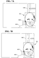
- step 222 and as shown in FIG. 7A, the connectivity analysis of the extracted pixels generates connected sets of pixels (e.g., pixels 701), i.e. sets of pixels that are adjacent or touching. Each of these connected sets of pixels 701 describe a low intensity region of the face.
- step 223 the pixel regions 701 resulting from steps 221-222 are filtered with respect to the region size. Regions having a small number of pixels due to camera noise or shadows are removed. Large regions generally cannot represent eyes, but instead correspond in general to hair.
- the size of the regions selected at this stage is in the interval [ ⁇ m , ⁇ M ] where ⁇ m , is the minimum and ⁇ M is the maximum number of pixels allowed by our system to describe a valid eye region. Threshold values ⁇ m , ⁇ M are determined based on the size of the ellipse that characterizes the head region (the ellipse being generated iteratively in step 215).
- the end result of step 223 is an image 702, such as that shown in FIG. 7B.
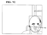
- step 224 the remaining components within the image of FIG. 7B are filtered based on anthropological measures, such as the geometrical distances between eyes and the expected position of the eyes inside a rectangular window (eye band) centered in the ellipse centroid.
- the eye regions are determined by analyzing the minimum and maximum distance between the regions inside this band.
- the output 230 of step 224 is an image, such as shown in FIG. 7C, whereby the eyes 703 have been detected.
- FIGS. 8A, 8B, 8C and 8D depict the results obtained by operating the present invention in a sample laboratory environment, based upon the teachings above.
- FIGS. 8A-8D comprise four different scenarios generated to demonstrate the performances under different conditions such as non-frontal poses, multiple occluding people back views, and faces with glasses.
- the face 812 of a single person 811 is detected, via ellipse 813.
- the ellipse 813 is properly fitted around the face 812 and the eyes 814 are detected even though the person 811 is wearing optical glasses on his face 812.
- FIG. 8B shows the back view of a single person 821 in the video scene.
- the ellipse 823 is fitted around the head of the person 821, but no eye is detected, indicating the robustness of the eye detection stage 202 of the present invention.
- FIGS. 8C and 8D show two scenarios in which two people 831A and 831B are present in the scene.
- the body of one person 831B is covering part of the body of the other person 831A.
- ellipses 833A and 833B are positioned around the faces 832A and 832B, and eyes 834A and 834B are detected.
- the face 832A of the person 831A in the back has a non-frontal position.
- the size of the two faces 832A and 832B are different.
- the faces 832A and 832B of both persons 831A and 831B are detected indicating the robustness of the system to variations in parameters such as size and position of the faces 832A and 832B.
Abstract
Description


- The width of the ellipse at iteration k + 1 is equal
to the distance between the right most and left most
point of the blob at the line corresponding to the
current centroid position, y (k) / o i.e.
- The centroid of the ellipse is located on the so-called
"vertical skeleton" of the blob representing
the person. The vertical skeleton is computed by
taking the middle point between the left-most and
the right-most points for each line of the blob.
The x (k+1) / 0 coordinate of the centroid of the ellipse
at iteration k + 1 is located on the vertical skeleton
at the line y (k) / 0 corresponding to the current
centroid position. Hence x (k+1) / 0 will be uniquely
determined as a function of y (k) / 0.
Claims (8)
- A system for processing a video image comprising pixels representing a foreground including one or more human faces, the system comprising;component analysis means (212,213) to process the pixels of the image to identify a region of connected components in the foreground of the image,ellipse fitting means (503,504,505,506,507) to perform an iterative ellipse fitting algorithm to fit one or more ellipses to the connected components in the identified region,means (301) to provide a model of borders for one or more separate individual faces in the identified region,probability computing means (403) to perform a computation of the probability of the model based on the ellipse or ellipses fitted in the identified region, and means (404,405) to iteratively adjust the model to maximise the probability computation.
- A system as claimed in claim 1, further comprising means (221) to identify sub-regions within the identified region that are below a selected low intensity threshold, means (223) to filter out those of the sub-regions that are below a selected small size or above a selected large size, and
means (224) to filter the remaining sub-regions based on anthropological measures to derive co-ordinates representing eyes. - A system as claimed in claim 1 or 2, in which the component analysis means (212,213) includes background subtraction and thresholding means (212) to subtract pixels representing background in the video image.
- A system as claimed in claim 1, 2 or 3, in which the ellipse fitting means (503,504,505,506,507) include means (503) to detect edges and vertical skeleton lines in the identified region, means (504) to form an initial centroid estimation, means (505) to compute the error in the centroid estimation, means (506) to compute a new centroid estimation and means (507) to stop the iteration when the distance between two centroid estimates is smaller than a predetermined threshold.
- A system as claimed in claim 1, 2, 3 or 4, in which the means (301) to provide a model of borders for one or more separate individual faces is effective to provide a selection of such models, each such model comprising a different selection of vertical borders.
- A system as claimed in claim 5, in which the probability computing means (403) are operable to compute the probability of each of a plurality of models, means being provided to select the model for which the highest probability is computed.
- A system as claimed in any one of the preceding claims, further comprising a video camera (110) to generate the said video image and storage means (150) to store the video image.
- A system as claimed in any one of the preceding claims, further comprising recognition and classification means to process the model to detect a face within the video image.
Applications Claiming Priority (4)
| Application Number | Priority Date | Filing Date | Title |
|---|---|---|---|
| US3181696P | 1996-11-26 | 1996-11-26 | |
| US31816P | 1996-11-26 | ||
| US08/859,902 US6184926B1 (en) | 1996-11-26 | 1997-05-21 | System and method for detecting a human face in uncontrolled environments |
| US859902 | 1997-05-21 |
Publications (2)
| Publication Number | Publication Date |
|---|---|
| EP0844582A2 true EP0844582A2 (en) | 1998-05-27 |
| EP0844582A3 EP0844582A3 (en) | 1999-05-26 |
Family
ID=26707653
Family Applications (1)
| Application Number | Title | Priority Date | Filing Date |
|---|---|---|---|
| EP97309444A Withdrawn EP0844582A3 (en) | 1996-11-26 | 1997-11-24 | System and method for detecting a human face |
Country Status (3)
| Country | Link |
|---|---|
| US (1) | US6184926B1 (en) |
| EP (1) | EP0844582A3 (en) |
| JP (1) | JPH10320562A (en) |
Cited By (12)
| Publication number | Priority date | Publication date | Assignee | Title |
|---|---|---|---|---|
| EP0984386A2 (en) * | 1998-09-05 | 2000-03-08 | Sharp Kabushiki Kaisha | Method of and apparatus for detecting a human face and observer tracking display |
| EP1017019A2 (en) * | 1998-12-31 | 2000-07-05 | Eastman Kodak Company | Method for automatic determination of main subjects in photographic images |
| EP1107166A2 (en) * | 1999-12-01 | 2001-06-13 | Matsushita Electric Industrial Co., Ltd. | Device and method for face image extraction, and recording medium having recorded program for the method |
| JP2001222719A (en) * | 1999-12-01 | 2001-08-17 | Matsushita Electric Ind Co Ltd | Face extracting device, face extracting method and recording medium for face extraction program |
| WO2003044737A1 (en) * | 2001-11-19 | 2003-05-30 | Koninklijke Philips Electronics N.V. | Computer vision method and system for blob-based analysis using a probabilistic framework |
| EP1330128A2 (en) * | 2001-12-03 | 2003-07-23 | Microsoft Corporation | Automatic detection and tracking of multiple individuals' faces using multiple cues |
| EP1510973A2 (en) * | 2003-08-29 | 2005-03-02 | Samsung Electronics Co., Ltd. | Method and apparatus for image-based photorealistic 3D face modeling |
| US6903782B2 (en) | 2001-03-28 | 2005-06-07 | Koninklijke Philips Electronics N.V. | System and method for performing segmentation-based enhancements of a video image |
| GB2409027A (en) * | 2003-12-11 | 2005-06-15 | Sony Uk Ltd | Face detection |
| EP1777643A1 (en) * | 2004-08-04 | 2007-04-25 | Daulet Kulenov | Method for automatically recognising a face on an electronic digitised image |
| EP1833002A1 (en) * | 2006-03-08 | 2007-09-12 | ID-Development AG | Method and apparatus for obtaining biometric image samples or biometric data |
| US8254639B2 (en) * | 2006-10-31 | 2012-08-28 | Sony Corporation | Image storage device, imaging device, image storage method, and program |
Families Citing this family (125)
| Publication number | Priority date | Publication date | Assignee | Title |
|---|---|---|---|---|
| USRE48056E1 (en) | 1991-12-23 | 2020-06-16 | Blanding Hovenweep, Llc | Ergonomic man-machine interface incorporating adaptive pattern recognition based control system |
| USRE46310E1 (en) | 1991-12-23 | 2017-02-14 | Blanding Hovenweep, Llc | Ergonomic man-machine interface incorporating adaptive pattern recognition based control system |
| USRE47908E1 (en) | 1991-12-23 | 2020-03-17 | Blanding Hovenweep, Llc | Ergonomic man-machine interface incorporating adaptive pattern recognition based control system |
| US10361802B1 (en) | 1999-02-01 | 2019-07-23 | Blanding Hovenweep, Llc | Adaptive pattern recognition based control system and method |
| US6850252B1 (en) | 1999-10-05 | 2005-02-01 | Steven M. Hoffberg | Intelligent electronic appliance system and method |
| US5903454A (en) | 1991-12-23 | 1999-05-11 | Hoffberg; Linda Irene | Human-factored interface corporating adaptive pattern recognition based controller apparatus |
| KR100595920B1 (en) * | 1998-01-26 | 2006-07-05 | 웨인 웨스터만 | Method and apparatus for integrating manual input |
| US6400830B1 (en) * | 1998-02-06 | 2002-06-04 | Compaq Computer Corporation | Technique for tracking objects through a series of images |
| US6332139B1 (en) * | 1998-11-09 | 2001-12-18 | Mega Chips Corporation | Information communication system |
| KR100361497B1 (en) * | 1999-01-08 | 2002-11-18 | 엘지전자 주식회사 | Method of extraction of face from video image |
| US7038715B1 (en) * | 1999-01-19 | 2006-05-02 | Texas Instruments Incorporated | Digital still camera with high-quality portrait mode |
| JP3617373B2 (en) * | 1999-06-03 | 2005-02-02 | オムロン株式会社 | Gate device |
| JP2000350123A (en) * | 1999-06-04 | 2000-12-15 | Fuji Photo Film Co Ltd | Picture selection device, camera, picture selection method and recording medium |
| JP2001357404A (en) * | 2000-06-14 | 2001-12-26 | Minolta Co Ltd | Picture extracting device |
| US7099510B2 (en) * | 2000-11-29 | 2006-08-29 | Hewlett-Packard Development Company, L.P. | Method and system for object detection in digital images |
| KR100416991B1 (en) * | 2001-01-11 | 2004-02-05 | 삼성전자주식회사 | Video terminal apparatus having displaying virtual background and implementing method thereof |
| WO2002077972A1 (en) * | 2001-03-27 | 2002-10-03 | Rast Associates, Llc | Head-worn, trimodal device to increase transcription accuracy in a voice recognition system and to process unvocalized speech |
| US20020172419A1 (en) * | 2001-05-15 | 2002-11-21 | Qian Lin | Image enhancement using face detection |
| JP2003061105A (en) * | 2001-06-07 | 2003-02-28 | Seiko Epson Corp | Image processing method, image processing program, image processing apparatus, and digital still camera using the image processing apparatus |
| US7274800B2 (en) * | 2001-07-18 | 2007-09-25 | Intel Corporation | Dynamic gesture recognition from stereo sequences |
| US8898106B2 (en) | 2001-08-01 | 2014-11-25 | T-System, Inc. | Method for entering, recording, distributing and reporting data |
| CA2359269A1 (en) * | 2001-10-17 | 2003-04-17 | Biodentity Systems Corporation | Face imaging system for recordal and automated identity confirmation |
| US20030113002A1 (en) * | 2001-12-18 | 2003-06-19 | Koninklijke Philips Electronics N.V. | Identification of people using video and audio eigen features |
| US7921036B1 (en) | 2002-04-30 | 2011-04-05 | Videomining Corporation | Method and system for dynamically targeting content based on automatic demographics and behavior analysis |
| US7209883B2 (en) * | 2002-05-09 | 2007-04-24 | Intel Corporation | Factorial hidden markov model for audiovisual speech recognition |
| US20030212552A1 (en) * | 2002-05-09 | 2003-11-13 | Liang Lu Hong | Face recognition procedure useful for audiovisual speech recognition |
| US7165029B2 (en) | 2002-05-09 | 2007-01-16 | Intel Corporation | Coupled hidden Markov model for audiovisual speech recognition |
| US8064650B2 (en) * | 2002-07-10 | 2011-11-22 | Hewlett-Packard Development Company, L.P. | File management of digital images using the names of people identified in the images |
| US7843495B2 (en) * | 2002-07-10 | 2010-11-30 | Hewlett-Packard Development Company, L.P. | Face recognition in a digital imaging system accessing a database of people |
| US20040012576A1 (en) * | 2002-07-16 | 2004-01-22 | Robert Cazier | Digital image display method and system |
| US6996460B1 (en) | 2002-10-03 | 2006-02-07 | Advanced Interfaces, Inc. | Method and apparatus for providing virtual touch interaction in the drive-thru |
| US7171043B2 (en) | 2002-10-11 | 2007-01-30 | Intel Corporation | Image recognition using hidden markov models and coupled hidden markov models |
| US20040136870A1 (en) * | 2002-10-25 | 2004-07-15 | Kochy Thomas E. | Automatic analysis apparatus |
| US7307654B2 (en) * | 2002-10-31 | 2007-12-11 | Hewlett-Packard Development Company, L.P. | Image capture and viewing system and method for generating a synthesized image |
| US7283650B1 (en) | 2002-11-27 | 2007-10-16 | Video Mining Corporation | Method and system for printing of automatically captured facial images augmented with promotional content |
| US7472063B2 (en) * | 2002-12-19 | 2008-12-30 | Intel Corporation | Audio-visual feature fusion and support vector machine useful for continuous speech recognition |
| US7734070B1 (en) | 2002-12-31 | 2010-06-08 | Rajeev Sharma | Method and system for immersing face images into a video sequence |
| US7203368B2 (en) * | 2003-01-06 | 2007-04-10 | Intel Corporation | Embedded bayesian network for pattern recognition |
| US7711155B1 (en) | 2003-04-14 | 2010-05-04 | Videomining Corporation | Method and system for enhancing three dimensional face modeling using demographic classification |
| US8593542B2 (en) * | 2005-12-27 | 2013-11-26 | DigitalOptics Corporation Europe Limited | Foreground/background separation using reference images |
| US8330831B2 (en) * | 2003-08-05 | 2012-12-11 | DigitalOptics Corporation Europe Limited | Method of gathering visual meta data using a reference image |
| US8682097B2 (en) | 2006-02-14 | 2014-03-25 | DigitalOptics Corporation Europe Limited | Digital image enhancement with reference images |
| US8896725B2 (en) * | 2007-06-21 | 2014-11-25 | Fotonation Limited | Image capture device with contemporaneous reference image capture mechanism |
| US7620218B2 (en) * | 2006-08-11 | 2009-11-17 | Fotonation Ireland Limited | Real-time face tracking with reference images |
| US7606417B2 (en) * | 2004-08-16 | 2009-10-20 | Fotonation Vision Limited | Foreground/background segmentation in digital images with differential exposure calculations |
| US7680342B2 (en) | 2004-08-16 | 2010-03-16 | Fotonation Vision Limited | Indoor/outdoor classification in digital images |
| US8494286B2 (en) * | 2008-02-05 | 2013-07-23 | DigitalOptics Corporation Europe Limited | Face detection in mid-shot digital images |
| JP2005050016A (en) * | 2003-07-31 | 2005-02-24 | National Aerospace Laboratory Of Japan | Shape recognition device, method, and program |
| WO2005031612A1 (en) * | 2003-09-26 | 2005-04-07 | Nikon Corporation | Electronic image accumulation method, electronic image accumulation device, and electronic image accumulation system |
| US6984039B2 (en) * | 2003-12-01 | 2006-01-10 | Eastman Kodak Company | Laser projector having silhouette blanking for objects in the output light path |
| JP2005242640A (en) * | 2004-02-26 | 2005-09-08 | Fuji Photo Film Co Ltd | Object detection method and device, and program |
| US7697026B2 (en) * | 2004-03-16 | 2010-04-13 | 3Vr Security, Inc. | Pipeline architecture for analyzing multiple video streams |
| US8345918B2 (en) * | 2004-04-14 | 2013-01-01 | L-3 Communications Corporation | Active subject privacy imaging |
| US7889381B2 (en) * | 2004-05-28 | 2011-02-15 | Fujifilm Corporation | Photo service system |
| US7430321B2 (en) * | 2004-09-09 | 2008-09-30 | Siemens Medical Solutions Usa, Inc. | System and method for volumetric tumor segmentation using joint space-intensity likelihood ratio test |
| NO321642B1 (en) * | 2004-09-27 | 2006-06-12 | Tandberg Telecom As | Procedure for encoding image sections |
| US8320641B2 (en) * | 2004-10-28 | 2012-11-27 | DigitalOptics Corporation Europe Limited | Method and apparatus for red-eye detection using preview or other reference images |
| US7386150B2 (en) * | 2004-11-12 | 2008-06-10 | Safeview, Inc. | Active subject imaging with body identification |
| JP4824411B2 (en) * | 2005-01-20 | 2011-11-30 | パナソニック株式会社 | Face extraction device, semiconductor integrated circuit |
| JP2006259924A (en) * | 2005-03-15 | 2006-09-28 | Omron Corp | Object authentication device, cellular phone, object authentication unit, object authentication method, and object authentication program |
| JP4830650B2 (en) * | 2005-07-05 | 2011-12-07 | オムロン株式会社 | Tracking device |
| KR100892022B1 (en) | 2005-08-12 | 2009-04-07 | 소니 컴퓨터 엔터테인먼트 인코포레이티드 | Face image display, face image display method, and face image display program |
| GB2432064B (en) * | 2005-10-31 | 2011-01-19 | Hewlett Packard Development Co | Method of triggering a detector to detect a moving feature within a video stream |
| JP4516516B2 (en) * | 2005-12-07 | 2010-08-04 | 本田技研工業株式会社 | Person detection device, person detection method, and person detection program |
| JP3962803B2 (en) * | 2005-12-16 | 2007-08-22 | インターナショナル・ビジネス・マシーンズ・コーポレーション | Head detection device, head detection method, and head detection program |
| US7692696B2 (en) | 2005-12-27 | 2010-04-06 | Fotonation Vision Limited | Digital image acquisition system with portrait mode |
| US7916897B2 (en) * | 2006-08-11 | 2011-03-29 | Tessera Technologies Ireland Limited | Face tracking for controlling imaging parameters |
| US20080059522A1 (en) * | 2006-08-29 | 2008-03-06 | International Business Machines Corporation | System and method for automatically creating personal profiles for video characters |
| US7689011B2 (en) * | 2006-09-26 | 2010-03-30 | Hewlett-Packard Development Company, L.P. | Extracting features from face regions and auxiliary identification regions of images for person recognition and other applications |
| US7987111B1 (en) * | 2006-10-30 | 2011-07-26 | Videomining Corporation | Method and system for characterizing physical retail spaces by determining the demographic composition of people in the physical retail spaces utilizing video image analysis |
| US8315463B2 (en) * | 2006-11-14 | 2012-11-20 | Eastman Kodak Company | User interface for face recognition |
| US7891818B2 (en) | 2006-12-12 | 2011-02-22 | Evans & Sutherland Computer Corporation | System and method for aligning RGB light in a single modulator projector |
| US8130203B2 (en) | 2007-01-03 | 2012-03-06 | Apple Inc. | Multi-touch input discrimination |
| US8269727B2 (en) | 2007-01-03 | 2012-09-18 | Apple Inc. | Irregular input identification |
| US7855718B2 (en) * | 2007-01-03 | 2010-12-21 | Apple Inc. | Multi-touch input discrimination |
| JP4639208B2 (en) * | 2007-03-16 | 2011-02-23 | 富士フイルム株式会社 | Image selection apparatus, image selection method, imaging apparatus, and program |
| US8331674B2 (en) * | 2007-04-06 | 2012-12-11 | International Business Machines Corporation | Rule-based combination of a hierarchy of classifiers for occlusion detection |
| TWI351001B (en) * | 2007-11-21 | 2011-10-21 | Ind Tech Res Inst | Method and apparatus for adaptive object detection |
| WO2009078957A1 (en) * | 2007-12-14 | 2009-06-25 | Flashfoto, Inc. | Systems and methods for rule-based segmentation for objects with full or partial frontal view in color images |
| US8629883B2 (en) * | 2008-02-28 | 2014-01-14 | Befun Bilgi Teknologileri A.S. | Method and system for generating online cartoon outputs |
| US9483237B2 (en) | 2008-02-28 | 2016-11-01 | Befun Bilgi Teknolojileri A.S. | Method and system for providing an image effects interface |
| US7953255B2 (en) | 2008-05-01 | 2011-05-31 | At&T Intellectual Property I, L.P. | Avatars in social interactive television |
| US8358317B2 (en) | 2008-05-23 | 2013-01-22 | Evans & Sutherland Computer Corporation | System and method for displaying a planar image on a curved surface |
| US8702248B1 (en) | 2008-06-11 | 2014-04-22 | Evans & Sutherland Computer Corporation | Projection method for reducing interpixel gaps on a viewing surface |
| US8238604B2 (en) * | 2008-08-18 | 2012-08-07 | Kabushiki Kaisha Toshiba | System and method for validation of face detection in electronic images |
| US8077378B1 (en) | 2008-11-12 | 2011-12-13 | Evans & Sutherland Computer Corporation | Calibration system and method for light modulation device |
| KR101593573B1 (en) * | 2009-06-19 | 2016-02-12 | 삼성전자주식회사 | Method of creating contents using camera in terminal and apparatus thereof |
| US8864581B2 (en) * | 2010-01-29 | 2014-10-21 | Microsoft Corporation | Visual based identitiy tracking |
| KR20120069331A (en) | 2010-12-20 | 2012-06-28 | 삼성전자주식회사 | Method of separating front view and background |
| US9641826B1 (en) | 2011-10-06 | 2017-05-02 | Evans & Sutherland Computer Corporation | System and method for displaying distant 3-D stereo on a dome surface |
| KR101901591B1 (en) * | 2011-11-01 | 2018-09-28 | 삼성전자주식회사 | Face recognition apparatus and control method for the same |
| AU2011253977B2 (en) | 2011-12-12 | 2015-04-09 | Canon Kabushiki Kaisha | Method, system and apparatus for selecting an image captured on an image capture device |
| US10691219B2 (en) | 2012-01-17 | 2020-06-23 | Ultrahaptics IP Two Limited | Systems and methods for machine control |
| US9070019B2 (en) | 2012-01-17 | 2015-06-30 | Leap Motion, Inc. | Systems and methods for capturing motion in three-dimensional space |
| US11493998B2 (en) | 2012-01-17 | 2022-11-08 | Ultrahaptics IP Two Limited | Systems and methods for machine control |
| US8638989B2 (en) | 2012-01-17 | 2014-01-28 | Leap Motion, Inc. | Systems and methods for capturing motion in three-dimensional space |
| US9679215B2 (en) | 2012-01-17 | 2017-06-13 | Leap Motion, Inc. | Systems and methods for machine control |
| US8693731B2 (en) | 2012-01-17 | 2014-04-08 | Leap Motion, Inc. | Enhanced contrast for object detection and characterization by optical imaging |
| US20130182079A1 (en) * | 2012-01-17 | 2013-07-18 | Ocuspec | Motion capture using cross-sections of an object |
| US9501152B2 (en) | 2013-01-15 | 2016-11-22 | Leap Motion, Inc. | Free-space user interface and control using virtual constructs |
| US9324292B2 (en) * | 2012-09-27 | 2016-04-26 | Hewlett-Packard Development Company, L.P. | Selecting an interaction scenario based on an object |
| US9191707B2 (en) | 2012-11-08 | 2015-11-17 | Bank Of America Corporation | Automatic display of user-specific financial information based on audio content recognition |
| US9285893B2 (en) | 2012-11-08 | 2016-03-15 | Leap Motion, Inc. | Object detection and tracking with variable-field illumination devices |
| US9027048B2 (en) | 2012-11-14 | 2015-05-05 | Bank Of America Corporation | Automatic deal or promotion offering based on audio cues |
| US10609285B2 (en) | 2013-01-07 | 2020-03-31 | Ultrahaptics IP Two Limited | Power consumption in motion-capture systems |
| US9465461B2 (en) | 2013-01-08 | 2016-10-11 | Leap Motion, Inc. | Object detection and tracking with audio and optical signals |
| US9459697B2 (en) | 2013-01-15 | 2016-10-04 | Leap Motion, Inc. | Dynamic, free-space user interactions for machine control |
| US9632658B2 (en) | 2013-01-15 | 2017-04-25 | Leap Motion, Inc. | Dynamic user interactions for display control and scaling responsiveness of display objects |
| US9754154B2 (en) | 2013-02-15 | 2017-09-05 | Microsoft Technology Licensing, Llc | Identification using depth-based head-detection data |
| US9702977B2 (en) | 2013-03-15 | 2017-07-11 | Leap Motion, Inc. | Determining positional information of an object in space |
| US10620709B2 (en) | 2013-04-05 | 2020-04-14 | Ultrahaptics IP Two Limited | Customized gesture interpretation |
| US9916009B2 (en) | 2013-04-26 | 2018-03-13 | Leap Motion, Inc. | Non-tactile interface systems and methods |
| US9747696B2 (en) | 2013-05-17 | 2017-08-29 | Leap Motion, Inc. | Systems and methods for providing normalized parameters of motions of objects in three-dimensional space |
| US10281987B1 (en) | 2013-08-09 | 2019-05-07 | Leap Motion, Inc. | Systems and methods of free-space gestural interaction |
| US9721383B1 (en) | 2013-08-29 | 2017-08-01 | Leap Motion, Inc. | Predictive information for free space gesture control and communication |
| US9632572B2 (en) | 2013-10-03 | 2017-04-25 | Leap Motion, Inc. | Enhanced field of view to augment three-dimensional (3D) sensory space for free-space gesture interpretation |
| US9996638B1 (en) | 2013-10-31 | 2018-06-12 | Leap Motion, Inc. | Predictive information for free space gesture control and communication |
| US9613262B2 (en) | 2014-01-15 | 2017-04-04 | Leap Motion, Inc. | Object detection and tracking for providing a virtual device experience |
| CN204480228U (en) | 2014-08-08 | 2015-07-15 | 厉动公司 | motion sensing and imaging device |
| CA3031085A1 (en) * | 2016-07-16 | 2018-01-25 | Ideal Perceptions Llc | Interactive projection system |
| US10297059B2 (en) | 2016-12-21 | 2019-05-21 | Motorola Solutions, Inc. | Method and image processor for sending a combined image to human versus machine consumers |
| US11295139B2 (en) | 2018-02-19 | 2022-04-05 | Intellivision Technologies Corp. | Human presence detection in edge devices |
| US11615623B2 (en) | 2018-02-19 | 2023-03-28 | Nortek Security & Control Llc | Object detection in edge devices for barrier operation and parcel delivery |
| US11875012B2 (en) | 2018-05-25 | 2024-01-16 | Ultrahaptics IP Two Limited | Throwable interface for augmented reality and virtual reality environments |
| US11275819B2 (en) | 2018-12-05 | 2022-03-15 | Bank Of America Corporation | Generative adversarial network training and feature extraction for biometric authentication |
Family Cites Families (10)
| Publication number | Priority date | Publication date | Assignee | Title |
|---|---|---|---|---|
| US5150432A (en) * | 1990-03-26 | 1992-09-22 | Kabushiki Kaisha Toshiba | Apparatus for encoding/decoding video signals to improve quality of a specific region |
| US5164992A (en) * | 1990-11-01 | 1992-11-17 | Massachusetts Institute Of Technology | Face recognition system |
| JP2973676B2 (en) * | 1992-01-23 | 1999-11-08 | 松下電器産業株式会社 | Face image feature point extraction device |
| US5689575A (en) * | 1993-11-22 | 1997-11-18 | Hitachi, Ltd. | Method and apparatus for processing images of facial expressions |
| US5781650A (en) * | 1994-02-18 | 1998-07-14 | University Of Central Florida | Automatic feature detection and age classification of human faces in digital images |
| US5497430A (en) * | 1994-11-07 | 1996-03-05 | Physical Optics Corporation | Method and apparatus for image recognition using invariant feature signals |
| JP3452685B2 (en) * | 1995-05-10 | 2003-09-29 | 三菱電機株式会社 | Face image processing device |
| JP3735893B2 (en) * | 1995-06-22 | 2006-01-18 | セイコーエプソン株式会社 | Face image processing method and face image processing apparatus |
| JP3350296B2 (en) * | 1995-07-28 | 2002-11-25 | 三菱電機株式会社 | Face image processing device |
| US5901244A (en) * | 1996-06-18 | 1999-05-04 | Matsushita Electric Industrial Co., Ltd. | Feature extraction system and face image recognition system |
-
1997
- 1997-05-21 US US08/859,902 patent/US6184926B1/en not_active Expired - Lifetime
- 1997-11-24 EP EP97309444A patent/EP0844582A3/en not_active Withdrawn
- 1997-11-26 JP JP9363370A patent/JPH10320562A/en active Pending
Non-Patent Citations (3)
| Title |
|---|
| "METHOD FOR EXTRACTING FACIAL FEATURES BY USING COLOR INFORMATION" IBM TECHNICAL DISCLOSURE BULLETIN, vol. 38, no. 10, 1 October 1995, pages 163-165, XP000540455 * |
| SABER E ET AL: "Face detection and facial feature extraction using color, shape and symmetry-based cost functions" PROCEEDINGS OF THE 13TH INTERNATIONAL CONFERENCE ON PATTERN RECOGNITION, PROCEEDINGS OF 13TH INTERNATIONAL CONFERENCE ON PATTERN RECOGNITION, VIENNA, AUSTRIA, 25-29 AUG. 1996, pages 654-658 vol.3, XP002097369 ISBN 0-8186-7282-X, 1996, Los Alamitos, CA, USA, IEEE Comput. Soc. Press, USA * |
| SOBOTTKA K ET AL: "FACE LOCALIZATION AND FACIAL FEATURE EXTRACTION BASED ON SHAPE AND COLOR INFORMATION" PROCEEDINGS OF THE INTERNATIONAL CONFERENCE ON IMAGE PROCESSING (IC, LAUSANNE, SEPT. 16 - 19, 1996, vol. 3, 16 September 1996, pages 483-486, XP000704075 INSTITUTE OF ELECTRICAL AND ELECTRONICS ENGINEERS * |
Cited By (24)
| Publication number | Priority date | Publication date | Assignee | Title |
|---|---|---|---|---|
| EP0984386A2 (en) * | 1998-09-05 | 2000-03-08 | Sharp Kabushiki Kaisha | Method of and apparatus for detecting a human face and observer tracking display |
| EP0984386A3 (en) * | 1998-09-05 | 2000-03-15 | Sharp Kabushiki Kaisha | Method of and apparatus for detecting a human face and observer tracking display |
| US6633655B1 (en) | 1998-09-05 | 2003-10-14 | Sharp Kabushiki Kaisha | Method of and apparatus for detecting a human face and observer tracking display |
| EP1017019A2 (en) * | 1998-12-31 | 2000-07-05 | Eastman Kodak Company | Method for automatic determination of main subjects in photographic images |
| EP1017019A3 (en) * | 1998-12-31 | 2007-01-10 | Eastman Kodak Company | Method for automatic determination of main subjects in photographic images |
| EP1107166A2 (en) * | 1999-12-01 | 2001-06-13 | Matsushita Electric Industrial Co., Ltd. | Device and method for face image extraction, and recording medium having recorded program for the method |
| JP2001222719A (en) * | 1999-12-01 | 2001-08-17 | Matsushita Electric Ind Co Ltd | Face extracting device, face extracting method and recording medium for face extraction program |
| EP1107166A3 (en) * | 1999-12-01 | 2008-08-06 | Matsushita Electric Industrial Co., Ltd. | Device and method for face image extraction, and recording medium having recorded program for the method |
| US6903782B2 (en) | 2001-03-28 | 2005-06-07 | Koninklijke Philips Electronics N.V. | System and method for performing segmentation-based enhancements of a video image |
| WO2003044737A1 (en) * | 2001-11-19 | 2003-05-30 | Koninklijke Philips Electronics N.V. | Computer vision method and system for blob-based analysis using a probabilistic framework |
| US7151843B2 (en) | 2001-12-03 | 2006-12-19 | Microsoft Corporation | Automatic detection and tracking of multiple individuals using multiple cues |
| EP1330128A2 (en) * | 2001-12-03 | 2003-07-23 | Microsoft Corporation | Automatic detection and tracking of multiple individuals' faces using multiple cues |
| EP1838104A3 (en) * | 2001-12-03 | 2009-09-30 | Microsoft Corporation | Automatic detection and tracking of multiple individuals' faces using multiple cues |
| US7433495B2 (en) | 2001-12-03 | 2008-10-07 | Microsoft Corporation | Automatic detection and tracking of multiple individuals using multiple cues |
| US7171025B2 (en) | 2001-12-03 | 2007-01-30 | Microsoft Corporation | Automatic detection and tracking of multiple individuals using multiple cues |
| US7428315B2 (en) | 2001-12-03 | 2008-09-23 | Microsoft Corporation | Automatic detection and tracking of multiple individuals using multiple cues |
| EP1330128A3 (en) * | 2001-12-03 | 2006-02-08 | Microsoft Corporation | Automatic detection and tracking of multiple individuals' faces using multiple cues |
| EP1510973A2 (en) * | 2003-08-29 | 2005-03-02 | Samsung Electronics Co., Ltd. | Method and apparatus for image-based photorealistic 3D face modeling |
| US7421149B2 (en) | 2003-12-11 | 2008-09-02 | Sony United Kingdom Limited | Object detection |
| GB2409027A (en) * | 2003-12-11 | 2005-06-15 | Sony Uk Ltd | Face detection |
| EP1777643A1 (en) * | 2004-08-04 | 2007-04-25 | Daulet Kulenov | Method for automatically recognising a face on an electronic digitised image |
| EP1777643A4 (en) * | 2004-08-04 | 2009-02-25 | Daulet Kulenov | Method for automatically recognising a face on an electronic digitised image |
| EP1833002A1 (en) * | 2006-03-08 | 2007-09-12 | ID-Development AG | Method and apparatus for obtaining biometric image samples or biometric data |
| US8254639B2 (en) * | 2006-10-31 | 2012-08-28 | Sony Corporation | Image storage device, imaging device, image storage method, and program |
Also Published As
| Publication number | Publication date |
|---|---|
| EP0844582A3 (en) | 1999-05-26 |
| US6184926B1 (en) | 2001-02-06 |
| JPH10320562A (en) | 1998-12-04 |
Similar Documents
| Publication | Publication Date | Title |
|---|---|---|
| EP0844582A2 (en) | System and method for detecting a human face | |
| JP4755202B2 (en) | Face feature detection method | |
| US7460693B2 (en) | Method and apparatus for the automatic detection of facial features | |
| Beymer | Face recognition under varying pose | |
| EP2192549B1 (en) | Target tracking device and target tracking method | |
| US7035456B2 (en) | Face detection in color images with complex background | |
| US7212665B2 (en) | Human pose estimation with data driven belief propagation | |
| US8520956B2 (en) | Optimized correlation filters for signal processing | |
| US7953253B2 (en) | Face detection on mobile devices | |
| US6741756B1 (en) | System and method for estimating the orientation of an object | |
| US20070154096A1 (en) | Facial feature detection on mobile devices | |
| Boehnen et al. | A fast multi-modal approach to facial feature detection | |
| Fukui et al. | Facial feature point extraction method based on combination of shape extraction and pattern matching | |
| Gourier et al. | Facial features detection robust to pose, illumination and identity | |
| De Smet et al. | A generalized EM approach for 3D model based face recognition under occlusions | |
| CN113837065A (en) | Image processing method and device | |
| Kervrann et al. | Generalized likelihood ratio-based face detection and extraction of mouth features | |
| Gürel | Development of a face recognition system | |
| Nefian et al. | Real-time detection of human faces in uncontrolled environments | |
| Poursaberi et al. | Modified multiscale vesselness filter for facial feature detection | |
| Cadavid et al. | Multi-modal biometric modeling and recognition of the human face and ear | |
| Jacques et al. | Improved head-shoulder human contour estimation through clusters of learned shape models | |
| Bobis et al. | Face recognition using binary thresholding for features extraction | |
| Chen et al. | Multi-cue facial feature detection and tracking | |
| Mona et al. | Automatic Human Face Counting in Digital Color Images |
Legal Events
| Date | Code | Title | Description |
|---|---|---|---|
| PUAI | Public reference made under article 153(3) epc to a published international application that has entered the european phase |
Free format text: ORIGINAL CODE: 0009012 |
|
| AK | Designated contracting states |
Kind code of ref document: A2 Designated state(s): DE FR GB |
|
| AX | Request for extension of the european patent |
Free format text: AL;LT;LV;MK;RO;SI |
|
| PUAL | Search report despatched |
Free format text: ORIGINAL CODE: 0009013 |
|
| AK | Designated contracting states |
Kind code of ref document: A3 Designated state(s): AT BE CH DE DK ES FI FR GB GR IE IT LI LU MC NL PT SE |
|
| AX | Request for extension of the european patent |
Free format text: AL;LT;LV;MK;RO;SI |
|
| 17P | Request for examination filed |
Effective date: 19991126 |
|
| AKX | Designation fees paid |
Free format text: DE FR GB |
|
| 17Q | First examination report despatched |
Effective date: 20001023 |
|
| STAA | Information on the status of an ep patent application or granted ep patent |
Free format text: STATUS: THE APPLICATION IS DEEMED TO BE WITHDRAWN |
|
| 18D | Application deemed to be withdrawn |
Effective date: 20010424 |