EP0842673A1 - Stabilized electrophysiology catheter and method for use - Google Patents
Stabilized electrophysiology catheter and method for use Download PDFInfo
- Publication number
- EP0842673A1 EP0842673A1 EP97308920A EP97308920A EP0842673A1 EP 0842673 A1 EP0842673 A1 EP 0842673A1 EP 97308920 A EP97308920 A EP 97308920A EP 97308920 A EP97308920 A EP 97308920A EP 0842673 A1 EP0842673 A1 EP 0842673A1
- Authority
- EP
- European Patent Office
- Prior art keywords
- tip portion
- section
- catheter
- catheter according
- anchor
- Prior art date
- Legal status (The legal status is an assumption and is not a legal conclusion. Google has not performed a legal analysis and makes no representation as to the accuracy of the status listed.)
- Granted
Links
Images


Classifications
-
- A—HUMAN NECESSITIES
- A61—MEDICAL OR VETERINARY SCIENCE; HYGIENE
- A61M—DEVICES FOR INTRODUCING MEDIA INTO, OR ONTO, THE BODY; DEVICES FOR TRANSDUCING BODY MEDIA OR FOR TAKING MEDIA FROM THE BODY; DEVICES FOR PRODUCING OR ENDING SLEEP OR STUPOR
- A61M25/00—Catheters; Hollow probes
- A61M25/01—Introducing, guiding, advancing, emplacing or holding catheters
- A61M25/0105—Steering means as part of the catheter or advancing means; Markers for positioning
- A61M25/0133—Tip steering devices
- A61M25/0147—Tip steering devices with movable mechanical means, e.g. pull wires
-
- A—HUMAN NECESSITIES
- A61—MEDICAL OR VETERINARY SCIENCE; HYGIENE
- A61M—DEVICES FOR INTRODUCING MEDIA INTO, OR ONTO, THE BODY; DEVICES FOR TRANSDUCING BODY MEDIA OR FOR TAKING MEDIA FROM THE BODY; DEVICES FOR PRODUCING OR ENDING SLEEP OR STUPOR
- A61M25/00—Catheters; Hollow probes
- A61M25/0021—Catheters; Hollow probes characterised by the form of the tubing
- A61M25/0041—Catheters; Hollow probes characterised by the form of the tubing pre-formed, e.g. specially adapted to fit with the anatomy of body channels
-
- A—HUMAN NECESSITIES
- A61—MEDICAL OR VETERINARY SCIENCE; HYGIENE
- A61M—DEVICES FOR INTRODUCING MEDIA INTO, OR ONTO, THE BODY; DEVICES FOR TRANSDUCING BODY MEDIA OR FOR TAKING MEDIA FROM THE BODY; DEVICES FOR PRODUCING OR ENDING SLEEP OR STUPOR
- A61M25/00—Catheters; Hollow probes
- A61M25/0067—Catheters; Hollow probes characterised by the distal end, e.g. tips
- A61M25/0068—Static characteristics of the catheter tip, e.g. shape, atraumatic tip, curved tip or tip structure
-
- A—HUMAN NECESSITIES
- A61—MEDICAL OR VETERINARY SCIENCE; HYGIENE
- A61M—DEVICES FOR INTRODUCING MEDIA INTO, OR ONTO, THE BODY; DEVICES FOR TRANSDUCING BODY MEDIA OR FOR TAKING MEDIA FROM THE BODY; DEVICES FOR PRODUCING OR ENDING SLEEP OR STUPOR
- A61M25/00—Catheters; Hollow probes
- A61M25/01—Introducing, guiding, advancing, emplacing or holding catheters
- A61M25/0105—Steering means as part of the catheter or advancing means; Markers for positioning
- A61M25/0133—Tip steering devices
- A61M25/0144—Tip steering devices having flexible regions as a result of inner reinforcement means, e.g. struts or rods
-
- A—HUMAN NECESSITIES
- A61—MEDICAL OR VETERINARY SCIENCE; HYGIENE
- A61M—DEVICES FOR INTRODUCING MEDIA INTO, OR ONTO, THE BODY; DEVICES FOR TRANSDUCING BODY MEDIA OR FOR TAKING MEDIA FROM THE BODY; DEVICES FOR PRODUCING OR ENDING SLEEP OR STUPOR
- A61M25/00—Catheters; Hollow probes
- A61M25/01—Introducing, guiding, advancing, emplacing or holding catheters
- A61M25/0105—Steering means as part of the catheter or advancing means; Markers for positioning
- A61M25/0133—Tip steering devices
- A61M25/0152—Tip steering devices with pre-shaped mechanisms, e.g. pre-shaped stylets or pre-shaped outer tubes
-
- A—HUMAN NECESSITIES
- A61—MEDICAL OR VETERINARY SCIENCE; HYGIENE
- A61M—DEVICES FOR INTRODUCING MEDIA INTO, OR ONTO, THE BODY; DEVICES FOR TRANSDUCING BODY MEDIA OR FOR TAKING MEDIA FROM THE BODY; DEVICES FOR PRODUCING OR ENDING SLEEP OR STUPOR
- A61M25/00—Catheters; Hollow probes
- A61M25/01—Introducing, guiding, advancing, emplacing or holding catheters
- A61M25/0105—Steering means as part of the catheter or advancing means; Markers for positioning
- A61M25/0133—Tip steering devices
- A61M2025/0161—Tip steering devices wherein the distal tips have two or more deflection regions
-
- A—HUMAN NECESSITIES
- A61—MEDICAL OR VETERINARY SCIENCE; HYGIENE
- A61M—DEVICES FOR INTRODUCING MEDIA INTO, OR ONTO, THE BODY; DEVICES FOR TRANSDUCING BODY MEDIA OR FOR TAKING MEDIA FROM THE BODY; DEVICES FOR PRODUCING OR ENDING SLEEP OR STUPOR
- A61M25/00—Catheters; Hollow probes
- A61M25/0067—Catheters; Hollow probes characterised by the distal end, e.g. tips
- A61M25/008—Strength or flexibility characteristics of the catheter tip
-
- A—HUMAN NECESSITIES
- A61—MEDICAL OR VETERINARY SCIENCE; HYGIENE
- A61M—DEVICES FOR INTRODUCING MEDIA INTO, OR ONTO, THE BODY; DEVICES FOR TRANSDUCING BODY MEDIA OR FOR TAKING MEDIA FROM THE BODY; DEVICES FOR PRODUCING OR ENDING SLEEP OR STUPOR
- A61M25/00—Catheters; Hollow probes
- A61M25/0067—Catheters; Hollow probes characterised by the distal end, e.g. tips
- A61M25/0082—Catheter tip comprising a tool
Definitions
- the present invention relates generally to steerable catheters, and more specifically to steerable electrophysiology catheters for use in mapping and ablation of cardiac tissue.
- the heart includes a number of pathways which are responsible for the propagation of signals necessary for normal electrical and mechanical function.
- the present invention is concerned with treatment of tachycardia, abnormally rapid rhythms of the heart caused by the presence of an arrhythmogenic site or accessory pathway which bypasses or short circuits the normal pathways in the heart.
- Tachycardias may be defined as ventricular tachycardias (VTs) and supraventricular tachycardias (SVTs).
- VTs originate in the left or right ventricle and are typically caused by arrhythmogenic sites associated with or without underlying heart disease.
- SVTs originate in the atria and are typically caused by an accessory pathway.
- Treatment of both ventricular and supraventricular tachycardias may be accomplished by a variety of approaches, including drugs, surgery, implantable pacemakers/ defibrillators, and catheter ablation. While drugs may be the treatment of choice for many patients, drugs typically only mask the symptoms and do not cure the underlying cause. Implantable devices, on the other hand, usually can correct an arrhythmia only after it occurs. Surgical and catheter-based treatments, in contrast, will actually cure the problem usually by ablating the abnormal arrhythmogenic tissue or accessory pathway responsible for the tachycardia. The catheter-based treatments rely on the application of various destructive energy sources to the target tissue including direct current electrical energy, radiofrequency electrical energy, laser energy, and the like.
- Radiofrequency (RF) ablation protocols which have proven to be highly effective in tachycardia treatment while exposing the patient to minimum side effects and risks.
- Radiofrequency catheter ablation is generally performed after an initial mapping procedure where the locations of the arrhythmogenic sites and accessory pathways are determined. After mapping, a catheter having a suitable electrode is introduced to the appropriate heart chamber and manipulated so that the electrode lies proximate the target tissue. Radiofrequency energy is then applied through the electrode to the cardiac tissue to ablate a region of the tissue which forms part of the arrhythmogenic site or the accessory pathway. By successfully destroying that tissue, the abnormal signaling patterns responsible for the tachycardia cannot be sustained.
- Methods and systems for performing RF ablation by controlling temperature at the ablation site are described in U.S. Patent No. 5,540,681 entitled "Method and System for Radiofrequency Ablation of Tissue.”
- Catheters designed for mapping and ablation frequently include a number of individual electrode bands mounted to the distal tip of the catheter so as to facilitate mapping of a wider area in less time, or to improve access to target sites for ablation.
- Such catheters are described in U.S. Patent No. 5,445,148 entitled “Intracardiac Electrical Potential Reference Catheter.”
- Such deflection may be accomplished through the use of pull wires secured to the distal tip which can be tensioned from the proximal end of the catheter to deflect the tip in the desired configuration.
- mapping and ablation catheters may facilitate rotational positioning of the distal tip, either by rotating the entire catheter from the proximal end, or by exerting torque on a core wire secured to the distal tip without rotating the catheter body itself. See U.S. Patent No. 5,545,200 entitled “Steerable Electrophysiology Catheter.”
- Catheters utilized in radiofrequency ablation are inserted into a major vein or artery, usually in the neck or groin area, and guided into the chambers of the heart by appropriate manipulation through the vein or artery.
- Such catheters must facilitate manipulation of the distal tip so that the distal electrode can be positioned against the tissue region to be ablated.
- the catheter must have a great deal of flexibility to follow the pathway of the major blood vessels into the heart, and the catheter must permit user manipulation of the tip even when the catheter is in a curved and twisted configuration. Because of the high degree of precision required for proper positioning of the tip electrode, the catheter must allow manipulation with a high degree of sensitivity and controllability.
- the distal portion of the catheter must be sufficiently resilient in order to be positioned against the wall of the heart and maintained in a position during ablation without being displaced by the movement of the beating heart.
- the present invention is directed to a stabilized electrophysiology catheter finding a special utility for mapping and ablating cardiac tissue within the right atrium, especially in the vicinity of the opening to the coronary sinus.
- the stabilized electrophysiology catheter includes a catheter shaft having a main body portion and a flexible tip portion.
- a plurality of electrodes are positioned along the tip portion.
- the tip portion includes a main section and an anchor section at the distal end of the tip portion.
- a radial deflector element extends along the catheter shaft and is coupled to the tip portion so the tip portion can be radially deflected in a first direction by longitudinal movement of the first manipulator element. In one embodiment the tip portion can be deflected beyond 360° to create an overlapping loop, if desired.
- the anchor section is configured to engage with and anchor to a cardiac structure, such as the ostium or opening of a vessel.
- the anchor section is offset from the main section and is preferably a reverse angle anchor section so that it extends in a direction opposite the direction of curvature of the main section.
- the anchor section could be a curved section but preferably extends at an obtuse angle, such as 140°, to the main section.
- the anchor section is also preferably pre-formed to its offset configuration; however, the anchor section could be actively manipulatable into its offset configuration.
- the invention finds particular utility in mapping, pacing and ablation of the right atrium with the anchor section engaged with the opening to the coronary sinus.
- the tip portion Introduced through the superior vena cava, the tip portion can form a generally J-shape as it is biased against the chamber wall and, typically, extends along the tricuspid annulus.
- the J-shaped portion of the tip can be positioned across the tricuspid valve or across the mitral valve for stability.
- the tip portion When introduced into the right atrium through the inferior vena cava, the tip portion can be deflected more than 360° as it engages the chamber wall.
- the invention can also be used in the left atrium with the anchor section anchored at the opening of any of the pulmonary veins.
- the tip portion may be deflectable, such as through the use of a core wire, to torque or laterally deflect all or part of the tip portion, preferably the proximal tip portion.
- the entire catheter shaft With the anchor section engaging an opening in the heart, the entire catheter shaft can be rotated or torqued by rotating or torquing the catheter handle to laterally deflect the curved tip portion in an effective manner.
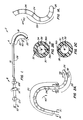
- Fig. 1 illustrates an electrophysiology catheter assembly 2 made according to the invention.
- Catheter assembly 2 includes broadly a catheter 4 extending from a proximal assembly 6.
- Proximal assembly 6 includes a handle 8 to which an electrical connector 10 is mounted.
- Longitudinally slidable manipulator wire control elements 12a and 12b and a rotatable core wire control element 14 are movably mounted to handle 8 and are used to manipulate catheter 4 as discussed below.
- Catheter 4 includes a main body portion 16, typically about 50 to 100 cm long and a tip portion 18, typically about 5 to 25 cm long. While both main body portion 16 and tip portion 18 are flexible, tip portion 18 is preferably more flexible (less stiff) than main body portion 16.
- Tip portion 18 includes a main section 20 extending along most of the length of tip portion 18, and an offset, preferably reverse-angle anchor section 22.
- Anchor section 22, shown best in Fig. 1A, is typically about 2-6 cm long and has a pre-formed shape defining a curved section extending over an arc of about 45-180 degrees.
- Tip portion 18 has a number of, typically about 10-24, band electrodes 24 along its length and a tip electrode 26 at the distal end of the anchor section 22. Electrodes 24, 26 may be constructed for both mapping and ablation.
- Figs. 2A and 2B illustrates cross-sectional views of one embodiment of the catheter shaft 28 taken along lines A-A and B-B of tip portion 18.
- Catheter shaft 28 defines a main lumen 30 through which a plurality of electric wires 32, one for each electrode 24, 26, extend between the electrodes and electrical connector 10.
- Main lumen 30 also houses a core wire 34; core wire 34 is connected to core wire control element 14 at its proximal end and to tip electrode 26 at its distal end. Alternatively, the core wire distal end can connect to an intermediate position, proximal to tip electrode 26.
- Rotating control element 14 causes core wire 34 to rotate thus causing the torquing of tip portion 18. When tip portion 18 is deflected radially into a curve, rotating control element 14 causes tip portion 18 to be deflected laterally.
- the type of lateral deflection that is in-plane (where the shape of tip portion does not change)or out-of-plane (where the shape of the tip portion changes), is determined in part by where the distal end of core wire 34 is connected. That is, connecting the distal end of core wire 34 to the proximal end of tip portion 18 causes an in-plane deflection of the tip portion while connecting the distal end of core wire 34 to anchor section 22 causes the out-of-plane lateral deflection of radially deflected tip portion 18. See U.S. Patent Application No. 08/694,363, filed August 8, 1996, entitled "Electrophysiology Catheter with Multi-function Wire and Method for Making" and assigned to the Assignee of the present application.
- radial deflection of main section 20 of tip portion 18 is caused by pulling or pushing on a manipulator wire 36a housed within a supplemental lumen 38.
- Manipulator wire 36a extends from control element 12a, along catheter shaft 28 and is anchored at the junction of main section 20 and anchor section 22.
- manipulator wire 36a is pulled to deflect tip portion 20 in the direction of arrow 40, which is the opposite direction of anchor section 22.
- offset anchor section 22 is termed an offset, reverse-angle anchor section because it extends in a direction which is generally reverse of the direction of the curve placed in main section 20 of tip portion 18 by the manipulation of manipulator wire 36a.
- Anchor section 22 is manipulated (radially deflected) by manipulator wire 36b attached to control element 12b.
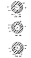
- Figs. 3A-3C illustrate another embodiment incorporating a pre-formed anchor section 22.
- manipulator wire 36b is anchored at proximal end of tip portion 18 (see Figs. 3C and 2A).
- Manipulator wire 36b is connected at its proximal end to control element 12b.
- Manipulator wire 36b is pulled to tilt the deflected tip section 18 sideways.
- manipulator wire 36a extends to the proximal end of curved anchor section 22 to radially deflect main portion 20 of tip 18 (see Figs. 3A and 2A).
- An axially slidable stiffener member 70 could be extended to different positions within tip portion 18 to change the stiffness, and thus the curvature size, of the tip portion.
- Stiffener member 70 extends through a protective tubing 72 within catheter tip 18.
- Member 70 can be actuated by a third sliding control similar to controls 12a, 12b of Fig. 1.
- Axially sliding stiffener member 70 in the distal direction increases the stiffness and thus the decreases the radius of tip portion 18 (see Fig. 5B), while sliding member 70 in the proximal direction decreases the stiffness and thus increases the radius of tip portion 18 (see Fig. 5A). See U.S. Patent No. 5,487,757 entitled "Multicurved Deflectable Catheter.”
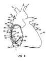
- Fig. 6 illustrates the placement of tip portion 18 into the right atrium 42 of a heart 44.
- tip portion 18 has been introduced into right atrium 42 through superior vena cava 46 with the anchor section 22 manipulated so that it anchors at the opening 48 to the coronary sinus 49.
- manipulator wire control element 12 and core wire control element 14 tip portion 18 can be urged against the chamber wall 50; such placement is stabilized by the engagement of anchor section 22 within opening 48.
- Fig. 6 also illustrates the placement of section 20 of tip portion 18 against the tricuspid annulus 52, that is the opening to the tricuspid valve. Other placements are also possible.
- catheter assembly 2 For atrial flutter, atrial fibrillation, and other atrial tachyardias, catheter assembly 2 provides at least the following four advantages.
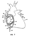
- Fig. 7 illustrates an alternative embodiment of catheter assembly 2 introduced into right atrium 42 of heart 44 through inferior vena cava 54.
- This embodiment is substantially the same as the embodiment of Figs. 1 and 6 except that tip portion 18 is longer.
- main section 20 of tip portion 18 curves more than 360° and forms an overlapping loop, again with anchor section 22 within the opening 48 to the coronary sinus to anchor the distal end of the catheter tip portion within the heart.
- main section 20 of tip portion 18 is maneuvered to press against chamber wall 50.
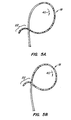
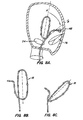
- Figs. 8A-8B illustrate a method of engaging the tricuspid valve 76 within the right atrium 42 of the heart with the overlapping loop 74 of tip portion 18.
- tip portion 18 is introduced into the heart chamber and overlapping loop 74 is formed therein.
- Manipulator wire 36b is actuated to tilt loop 74 sideways against the tricuspid valve 76.
- Fig. 8A shows tip portion 18 with a primary loop but no tilt. To achieve this, distal manipulator wire 36a is activated, but not proximal manipulator wire 36b.
- Fig. 8B shows how the loop tilts sideways to match the angle of tricuspid valve 76 when manipulator wire 36b is activated.
- a version of the catheter which does not have proximal manipulator wire 36b can still be maneuvered against tricuspid valve annulus 52.
- This design is described below with reference to Figs. 10-11.
- anchor section 22 is placed in coronary sinus 49, then a loop is formed by pulling manipulator wire 36, and the loop is rotated into place against tricuspid annulus 52 by torquing main body portion 16 through the rotation of handle 8.
- Figs. 9A and 9B illustrate a method of delivering tip portion 18 of the catheter into left atrium 78.
- tip portion 18 is introduced into right atrium 42 and delivered through a transseptal puncture 80 into left atrium 78.
- Tip portion 18 is then manipulated to pass through one of the pulmonary vein openings 82 in left atrium 78. This manipulation may require tip portion 18 to have a substantially vertical position (Fig. 9A) within left atrium 78, a substantially horizontal position (Fig. 9B) in the left atrium or other configurations depending on the particular procedure.
- Manipulation of tip section 18 into various positions in left atrium 78 can be facilitated by anchoring anchor section 22 into a pulmonary vein opening 82 as shown.
- the resulting improved contact between the electrodes and left atrial tissue can facilitate the mapping and ablation of atrial fibrillation and other atrial tachycardias.
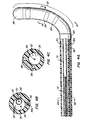
- Fig. 10 illustrates the tip portion 18 of an alternative embodiment of the invention.
- Anchor section 22 is an essentially straight section defining an angle 58 to the distal end of main section 20.
- Angle 58 preferably ranges from about 45° to about 180°, and more preferably is about 140°, while the length of anchor section 22 is preferably about 1 to 6 cm long, and more preferably is about 4 cm long.
- a single manipulator wire 36 is used.
- manipulator wire 36 passes through an insert 60, see Figs. 11 and 12B, and is prevented from pulling back through the insert 60 by a ball 62 at its distal end.
- Core wire 34 also terminates at insert 60 by passing through the insert and then doubling back over to a second bore formed in the insert for receipt of the core wire 34. This is also illustrated in Figs. 11 and 12B.
- Insert 60 has a center bore 64 through which electrical wires 32, connected to electrodes 24 along anchor section 22, pass.
- Tip electrode 26 has its electrical wire 32a pass through insert 60 in a manner to be embedded within and affixed to insert 60 as illustrated in Fig. 12B.
- This securing of wire 32a to insert 60 is a safety feature to help ensure that tip electrode 26 does not become dislodged from anchor section 22.
- An alternative to the separate tip electrode 26 is a thermally formed rounded plastic tip, formed from the tip tubing itself. This design is described in Patent Application 08/511,823, filed August 7, 1995 and entitled "Simplified Torquing Electrode Catheter.”
- the embodiment of Fig. 10 includes one manipulator wire 36 and a slide wire 66 which connects to control element 12b at proximal end assembly 6.
- Slide wire control element 12b causes the distal end of slide wire 66 to move along the length of main section 20 of tip portion 18.
- slide wire 66 is housed within a polyimide sleeve 68. When slide wire 66 is fully extended, that is moved to its most distal position, section 20 of tip portion 18 is stiffer than when slide wire 66 is pulled to its most proximal position.
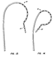
- FIG. 13 illustrates the shape of tip portion 18 when slide wire 66 is moved to its most proximal position and manipulator wire 36 is pulled to create a larger diameter curve.
- Fig. 14 illustrates the shape of tip portion 18 when slide wire 66 is advanced to its most distal position and manipulator wire 36 is pulled to create a smaller diameter curve.
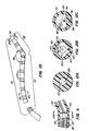
- Fig. 16 illustrates tip portion 18 of a preferred embodiment of the invention which is very similar to that of Fig. 10 in function.
- Anchor section 22 includes main lumen 30 (see Fig. 17A) housing sleeve 68, manipulator wire 36, and electric wires 32.
- Sleeve 68 is, as in the prior embodiments, used for accommodating the extension of slide wire 66.
- Figs. 17B and 17C illustrate the formation of main lumen 30 as well as supplemental lumens 38, 38a along main section 20.
- Manipulator wire 36 is housed within supplemental lumen 38 while core wire 34 extends through supplemental lumen 38a.
- the distal end of supplemental lumen 38a has a flattened rectangular shape as does the distal end of core wire 34a.
- This provides a relatively simple but effective means for providing torque transmission from core wire 34a to tip portion 18; in this embodiment the torque is transmitted to the distal end of main section 20 of the tip section.
- Fig. 17D illustrates the use of strengthening braid 84 as a part of catheter shaft 28 along main body portion 16. There is only the single main lumen 30 along main body portion 16 within which electric wires 32, core wire 34a, manipulator wire 36, and slide wire 66 are housed.
- catheter shaft 28 along main section 20 defines three lumens through which the various elements pass.
- core wire 34a is rotatably coupled to tip portion 18 by the shape of the distal ends of core wire 34a and supplemental lumen 38a.
- manipulator wire 36 does not terminate at the junction of sections 20, 22 but rather extends to an insulating anchor 86 positioned adjacent tip electrode 26.
- manipulator wire 36 can be pushed or pulled to cause corresponding radial deflection of main section 20 of tip portion 18, but without substantially affecting the shape of either anchor section 22 or angle 58 due to the central location of manipulator wire 36.
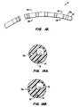
- Figs. 18, 19A and 19B show still a further embodiment of a tip 18 which omits or deletes anchor section 22.
- the embodiment of Figs. 18-19B does not use a core wire 34a, which would provide lateral deflection, but does have a manipulator wire 36 for radial deflection of tip portion 18.
- slide wire 66 is used to permit the size of the radial deflection curve to be changed.
- Manipulator wire 36 is secured to and terminates at an insulating anchor 86a adjacent to electrode 26 by being doubled over similar to the way core wire 34 is secured to insert 60 as shown in Figs. 11 and 12B.
- the final 1 cm of tip 18 adjacent anchor 86a has a single, centrally-positioned lumen to enhance bonding to anchor 86a and thus improve the ease of assembly of the catheter.
- the embodiment of Figs. 18-19B while lacking the ability to be anchored to opening 48 of coronary sinus 49 as in the above-described embodiments, it is somewhat simpler in construction, and thus, more economical, and is quite suited for general purpose mapping, pacing and ablation throughout the atrium.
- band electrodes 24 could be replaced by, for example, long coil electrodes, especially if they are used for ablation.
- shape of offset, reverse-angle anchor section 22 could have other shapes, such as a 360° loop or spiral coil, designed to engage the opening 48 to the coronary sinus, or other cardiac openings such as the openings to pulmonary veins 56.
Abstract
Description
Claims (17)
- A stabilized electrophysiology catheter comprising:a catheter shaft having a main body portion and a flexible tip portion, the tip portion terminating at a distal end;a plurality of electrodes along said tip portion;a radial deflector element, extending along the catheter shaft, coupled to the tip portion whereby at least a part of the main section of the tip portion is radially deflectable in a first direction by longitudinal movement of the manipulator element; andthe tip portion comprising a main section and a distal section at said distal end of said tip portion, said distal section comprising an offset anchor section configured to engage with and anchor to a coronary opening.
- The catheter according to claim 1 wherein the offset anchor section is an offset, reverse-angle anchor section extending in a second direction generally opposite said first direction.
- The catheter according to claim 1 wherein said tip portion is configurable to a generally J-shaped configuration when introduced through a superior vena cava.
- The catheter according to claim 1 wherein said tip portion is configurable to an overlapping loop configuration when introduced through an inferior vena cava.
- The catheter according to claim 1 wherein said anchor section is a pre-formed section.
- The catheter according to claim 1 wherein the anchor section is a generally straight section extending at an angle of between about 45°-180° to the main section.
- The catheter according to claim 6 wherein the anchor section is about 4 cm long and the angle is about 140°.
- The catheter according to claim 1 further comprising a manipulator element extending along the catheter shaft.
- The catheter according to claim 8 wherein a manipulator element is capable of deflecting the main portion at least 180°.
- The catheter according to claim 8 wherein said catheter shaft comprises a torquable core wire non-rotatably coupled to the tip portion.
- The catheter according to claim 1 wherein said electrodes extend along said main section and said anchor section.
- The catheter according to claim 1 wherein said anchor section is configured to engage with and anchor to an opening to a coronary sinus.
- The catheter according to claim 1 wherein said electrodes are mapping electrodes.
- The catheter according to claim 1 further comprising a longitudinally-movable stiffening mandrel within the catheter shaft so said deflectable main section is an adjustable-radius, deflectable main section.
- The catheter according to claim 1 further comprising a second radial deflector element, whereby actuating the second radial deflector element when the main section is in a curved configuration causes the curved main section to deflect laterally.
- The catheter according to claim 15 wherein the deflectable main section is movable into an overlapping loop configuration, wherein actuating the second radial deflector element causes the looped main section to be deflected laterally to position the electrodes at an angle approximating that of the tricuspid valve annulus of the right atrium.
- The catheter according to claim 1 wherein the tip portion is movable to an overlapping loop configuration so that torquing the main body portion of the catheter shaft causes the looped tip portion to be positioned at an angle approximating that of a tricuspid annulus.
Applications Claiming Priority (6)
| Application Number | Priority Date | Filing Date | Title |
|---|---|---|---|
| US3072996P | 1996-11-08 | 1996-11-08 | |
| US30729 | 1996-11-08 | ||
| US86533197A | 1997-05-29 | 1997-05-29 | |
| US865331 | 1997-05-29 | ||
| US08/949,408 US6002955A (en) | 1996-11-08 | 1997-10-14 | Stabilized electrophysiology catheter and method for use |
| US949408 | 1997-10-14 |
Publications (2)
| Publication Number | Publication Date |
|---|---|
| EP0842673A1 true EP0842673A1 (en) | 1998-05-20 |
| EP0842673B1 EP0842673B1 (en) | 2003-01-15 |
Family
ID=27363711
Family Applications (1)
| Application Number | Title | Priority Date | Filing Date |
|---|---|---|---|
| EP97308920A Expired - Lifetime EP0842673B1 (en) | 1996-11-08 | 1997-11-06 | Stabilized electrophysiology catheter and method for use |
Country Status (4)
| Country | Link |
|---|---|
| US (1) | US6002955A (en) |
| EP (1) | EP0842673B1 (en) |
| JP (1) | JPH11401A (en) |
| DE (1) | DE69718423T2 (en) |
Cited By (26)
| Publication number | Priority date | Publication date | Assignee | Title |
|---|---|---|---|---|
| DE10337580A1 (en) * | 2003-08-16 | 2005-03-17 | Dr. Osypka Gmbh | Catheter with elastically bendable or steerable end |
| WO2006122061A1 (en) * | 2005-05-06 | 2006-11-16 | Acumen Medical, Inc. | Complexly shaped steerable catheters and methods for making and using them |
| WO2009052261A1 (en) * | 2007-10-19 | 2009-04-23 | Pressure Products Medical Supplies, Inc. | Transseptal guidewire |
| US7774039B2 (en) | 2006-09-05 | 2010-08-10 | Boston Scientific Scimed, Inc. | Multi-bend steerable mapping catheter |
| US7963947B2 (en) | 2008-01-16 | 2011-06-21 | Pressure Products Medical Supplies, Inc. | Apparatus, system, and method of shielding the sharp tip of a transseptal guidewire |
| US7993350B2 (en) | 2004-10-04 | 2011-08-09 | Medtronic, Inc. | Shapeable or steerable guide sheaths and methods for making and using them |
| WO2013016722A3 (en) * | 2011-07-28 | 2013-04-11 | Vascomed Gmbh | Steerable catheters and methods for making them |
| US8725228B2 (en) | 2009-02-20 | 2014-05-13 | Boston Scientific Scimed, Inc. | Steerable catheter having intermediate stiffness transition zone |
| US8956280B2 (en) | 2002-05-30 | 2015-02-17 | Intuitive Surgical Operations, Inc. | Apparatus and methods for placing leads using direct visualization |
| US9192287B2 (en) | 2005-10-25 | 2015-11-24 | Intuitive Surgical Operations, Inc. | Tissue visualization device and method variations |
| US9226648B2 (en) | 2006-12-21 | 2016-01-05 | Intuitive Surgical Operations, Inc. | Off-axis visualization systems |
| US9332893B2 (en) | 2005-02-02 | 2016-05-10 | Intuitive Surgical Operations, Inc. | Delivery of biological compounds to ischemic and/or infarcted tissue |
| EP2913080A4 (en) * | 2012-10-23 | 2016-07-06 | Aleksandr Grigorievitch Osiev | Method for the catheterization of the coronary arteries and catheter for the implementation thereof |
| US9510732B2 (en) | 2005-10-25 | 2016-12-06 | Intuitive Surgical Operations, Inc. | Methods and apparatus for efficient purging |
| US9526401B2 (en) | 2005-02-02 | 2016-12-27 | Intuitive Surgical Operations, Inc. | Flow reduction hood systems |
| US10004388B2 (en) | 2006-09-01 | 2018-06-26 | Intuitive Surgical Operations, Inc. | Coronary sinus cannulation |
| US10064540B2 (en) | 2005-02-02 | 2018-09-04 | Intuitive Surgical Operations, Inc. | Visualization apparatus for transseptal access |
| US10070772B2 (en) | 2006-09-01 | 2018-09-11 | Intuitive Surgical Operations, Inc. | Precision control systems for tissue visualization and manipulation assemblies |
| EP3381395A1 (en) * | 2017-03-28 | 2018-10-03 | Biosense Webster (Israel) Ltd. | Catheter with floating curvature |
| US10092172B2 (en) | 2007-05-08 | 2018-10-09 | Intuitive Surgical Operations, Inc. | Complex shape steerable tissue visualization and manipulation catheter |
| US10278588B2 (en) | 2005-02-02 | 2019-05-07 | Intuitive Surgical Operations, Inc. | Electrophysiology mapping and visualization system |
| US10470643B2 (en) | 2006-06-14 | 2019-11-12 | Intuitive Surgical Operations, Inc. | In-vivo visualization systems |
| US10888644B2 (en) | 2019-02-06 | 2021-01-12 | inQB8 Medical Technologies, LLC | Intra-cardiac left atrial and dual support systems |
| US11406250B2 (en) | 2005-02-02 | 2022-08-09 | Intuitive Surgical Operations, Inc. | Methods and apparatus for treatment of atrial fibrillation |
| US11478152B2 (en) | 2005-02-02 | 2022-10-25 | Intuitive Surgical Operations, Inc. | Electrophysiology mapping and visualization system |
| US11622689B2 (en) | 2008-11-14 | 2023-04-11 | Intuitive Surgical Operations, Inc. | Mapping and real-time imaging a plurality of ablation lesions with registered ablation parameters received from treatment device |
Families Citing this family (130)
| Publication number | Priority date | Publication date | Assignee | Title |
|---|---|---|---|---|
| JP3469058B2 (en) * | 1997-09-12 | 2003-11-25 | エクセルメデイ株式会社 | Electrode catheter |
| EP1196212A2 (en) | 1999-06-15 | 2002-04-17 | Cryocath Technologies inc. | Steerable catheter |
| US7815590B2 (en) | 1999-08-05 | 2010-10-19 | Broncus Technologies, Inc. | Devices for maintaining patency of surgically created channels in tissue |
| US7022088B2 (en) * | 1999-08-05 | 2006-04-04 | Broncus Technologies, Inc. | Devices for applying energy to tissue |
| US6628976B1 (en) | 2000-01-27 | 2003-09-30 | Biosense Webster, Inc. | Catheter having mapping assembly |
| US6711428B2 (en) | 2000-01-27 | 2004-03-23 | Biosense Webster, Inc. | Catheter having mapping assembly |
| US6795721B2 (en) | 2000-01-27 | 2004-09-21 | Biosense Webster, Inc. | Bidirectional catheter having mapping assembly |
| US7570982B2 (en) * | 2000-01-27 | 2009-08-04 | Biosense Webster, Inc. | Catheter having mapping assembly |
| US6638268B2 (en) | 2000-04-07 | 2003-10-28 | Imran K. Niazi | Catheter to cannulate the coronary sinus |
| US6514250B1 (en) * | 2000-04-27 | 2003-02-04 | Medtronic, Inc. | Suction stabilized epicardial ablation devices |
| US6558382B2 (en) * | 2000-04-27 | 2003-05-06 | Medtronic, Inc. | Suction stabilized epicardial ablation devices |
| AU2001273468B2 (en) | 2000-07-13 | 2005-05-26 | Recor Medical, Inc. | Energy application with inflatable annular lens |
| EP2275175B1 (en) | 2000-07-13 | 2016-08-24 | ReCor Medical, Inc. | Thermal treatment apparatus with ultrasonic energy application |
| US6926669B1 (en) * | 2000-10-10 | 2005-08-09 | Medtronic, Inc. | Heart wall ablation/mapping catheter and method |
| US6728563B2 (en) | 2000-11-29 | 2004-04-27 | St. Jude Medical, Daig Division, Inc. | Electrophysiology/ablation catheter having “halo” configuration |
| US7081114B2 (en) | 2000-11-29 | 2006-07-25 | St. Jude Medical, Atrial Fibrillation Division, Inc. | Electrophysiology/ablation catheter having lariat configuration of variable radius |
| IL140780A0 (en) * | 2001-01-08 | 2002-02-10 | Gaber Benny | Deflectable guiding apparatus |
| US6571125B2 (en) | 2001-02-12 | 2003-05-27 | Medtronic, Inc. | Drug delivery device |
| US6564096B2 (en) | 2001-02-28 | 2003-05-13 | Robert A. Mest | Method and system for treatment of tachycardia and fibrillation |
| WO2002094334A1 (en) | 2001-05-21 | 2002-11-28 | Medtronic, Inc. | Malleable elongated medical device |
| US20030036698A1 (en) * | 2001-08-16 | 2003-02-20 | Robert Kohler | Interventional diagnostic catheter and a method for using a catheter to access artificial cardiac shunts |
| US7708712B2 (en) | 2001-09-04 | 2010-05-04 | Broncus Technologies, Inc. | Methods and devices for maintaining patency of surgically created channels in a body organ |
| US6733499B2 (en) | 2002-02-28 | 2004-05-11 | Biosense Webster, Inc. | Catheter having circular ablation assembly |
| US7462184B2 (en) * | 2002-05-06 | 2008-12-09 | Pressure Products Medical Supplies Inc. | Introducer for accessing the coronary sinus of a heart |
| US20040082859A1 (en) | 2002-07-01 | 2004-04-29 | Alan Schaer | Method and apparatus employing ultrasound energy to treat body sphincters |
| US6866662B2 (en) * | 2002-07-23 | 2005-03-15 | Biosense Webster, Inc. | Ablation catheter having stabilizing array |
| US7037290B2 (en) * | 2002-12-16 | 2006-05-02 | Medtronic, Inc. | Multi-lumen steerable catheter |
| US6945956B2 (en) * | 2002-12-23 | 2005-09-20 | Medtronic, Inc. | Steerable catheter |
| US7387629B2 (en) * | 2003-01-21 | 2008-06-17 | St. Jude Medical, Atrial Fibrillation Division, Inc. | Catheter design that facilitates positioning at tissue to be diagnosed or treated |
| US7819866B2 (en) | 2003-01-21 | 2010-10-26 | St. Jude Medical, Atrial Fibrillation Division, Inc. | Ablation catheter and electrode |
| JP2006518648A (en) | 2003-02-20 | 2006-08-17 | プロリズム,インコーポレイテッド | Cardiac ablation device |
| WO2004078066A2 (en) * | 2003-03-03 | 2004-09-16 | Sinus Rhythm Technologies, Inc. | Primary examiner |
| EP1605866B1 (en) | 2003-03-03 | 2016-07-06 | Syntach AG | Electrical conduction block implant device |
| US7142903B2 (en) | 2003-03-12 | 2006-11-28 | Biosense Webster, Inc. | Catheter with contractable mapping assembly |
| US7818048B2 (en) * | 2003-06-02 | 2010-10-19 | Biosense Webster, Inc. | Catheter and method for mapping a pulmonary vein |
| US7101362B2 (en) * | 2003-07-02 | 2006-09-05 | St. Jude Medical, Atrial Fibrillation Division, Inc. | Steerable and shapable catheter employing fluid force |
| US8308682B2 (en) | 2003-07-18 | 2012-11-13 | Broncus Medical Inc. | Devices for maintaining patency of surgically created channels in tissue |
| US8002740B2 (en) | 2003-07-18 | 2011-08-23 | Broncus Technologies, Inc. | Devices for maintaining patency of surgically created channels in tissue |
| SE526861C2 (en) | 2003-11-17 | 2005-11-15 | Syntach Ag | Tissue lesion creation device and a set of devices for the treatment of cardiac arrhythmia disorders |
| US7632266B2 (en) * | 2004-02-17 | 2009-12-15 | Boston Scientific Scimed, Inc. | Endoscopic devices and related methods of use |
| US9398967B2 (en) | 2004-03-02 | 2016-07-26 | Syntach Ag | Electrical conduction block implant device |
| US8007495B2 (en) * | 2004-03-31 | 2011-08-30 | Biosense Webster, Inc. | Catheter for circumferential ablation at or near a pulmonary vein |
| WO2005113057A1 (en) | 2004-05-17 | 2005-12-01 | C. R. Bard, Inc. | Articulated catheter |
| US7250049B2 (en) * | 2004-05-27 | 2007-07-31 | St. Jude Medical, Atrial Fibrillation Division, Inc. | Ablation catheter with suspension system incorporating rigid and flexible components |
| US7122034B2 (en) * | 2004-05-27 | 2006-10-17 | St. Jude Medical, Atrial Fibrillation Division, Inc. | Curved ablation catheter |
| US8409167B2 (en) | 2004-07-19 | 2013-04-02 | Broncus Medical Inc | Devices for delivering substances through an extra-anatomic opening created in an airway |
| US8409191B2 (en) * | 2004-11-04 | 2013-04-02 | Boston Scientific Scimed, Inc. | Preshaped ablation catheter for ablating pulmonary vein ostia within the heart |
| US7691095B2 (en) | 2004-12-28 | 2010-04-06 | St. Jude Medical, Atrial Fibrillation Division, Inc. | Bi-directional steerable catheter control handle |
| US8858495B2 (en) | 2004-12-28 | 2014-10-14 | St. Jude Medical, Atrial Fibrillation Division, Inc. | Five degree of freedom ultrasound catheter and catheter control handle |
| US8583260B2 (en) | 2004-12-28 | 2013-11-12 | St. Jude Medical, Atrial Fibrillation Division, Inc. | Long travel steerable catheter actuator |
| US8273285B2 (en) | 2005-01-10 | 2012-09-25 | St. Jude Medical, Atrial Fibrillation Division, Inc. | Steerable catheter and methods of making the same |
| US8050746B2 (en) | 2005-02-02 | 2011-11-01 | Voyage Medical, Inc. | Tissue visualization device and method variations |
| CN100548410C (en) * | 2005-03-04 | 2009-10-14 | 导管治疗有限公司 | Modular catheter and the conduit tube component that comprises this handle |
| CA2599976A1 (en) * | 2005-03-04 | 2006-09-08 | Cathrx Ltd | A catheter handle and a catheter assembly including such a handle |
| US7591784B2 (en) | 2005-04-26 | 2009-09-22 | St. Jude Medical, Atrial Fibrillation Division, Inc. | Bi-directional handle for a catheter |
| US8535303B2 (en) * | 2005-05-05 | 2013-09-17 | Boston Scientific Scimed, Inc. | Preshaped localization catheter, system, and method for graphically reconstructing pulmonary vein ostia |
| US7819868B2 (en) | 2005-06-21 | 2010-10-26 | St. Jude Medical, Atrial Fibrilation Division, Inc. | Ablation catheter with fluid distribution structures |
| US8777929B2 (en) * | 2005-06-28 | 2014-07-15 | St. Jude Medical, Atrial Fibrillation Division, Inc. | Auto lock for catheter handle |
| US7465288B2 (en) * | 2005-06-28 | 2008-12-16 | St. Jude Medical, Atrial Fibrillation Division, Inc. | Actuation handle for a catheter |
| US7623899B2 (en) * | 2005-09-16 | 2009-11-24 | Biosense Webster, Inc. | Catheter with flexible pre-shaped tip section |
| US20070156114A1 (en) * | 2005-12-29 | 2007-07-05 | Worley Seth J | Deflectable catheter with a flexibly attached tip section |
| WO2007120505A1 (en) * | 2006-03-31 | 2007-10-25 | C. R. Bard, Inc. | Catheter including arcuate transition region |
| US20070270679A1 (en) | 2006-05-17 | 2007-11-22 | Duy Nguyen | Deflectable variable radius catheters |
| US7774051B2 (en) | 2006-05-17 | 2010-08-10 | St. Jude Medical, Atrial Fibrillation Division, Inc. | System and method for mapping electrophysiology information onto complex geometry |
| EP2021846B1 (en) | 2006-05-19 | 2017-05-03 | Koninklijke Philips N.V. | Ablation device with optimized input power profile |
| US8444637B2 (en) | 2006-12-29 | 2013-05-21 | St. Jude Medical, Atrial Filbrillation Division, Inc. | Steerable ablation device |
| AU2008202483B2 (en) | 2007-06-15 | 2011-07-14 | Cathrx Ltd | A deflectable stylet |
| US7914515B2 (en) * | 2007-07-18 | 2011-03-29 | St. Jude Medical, Atrial Fibrillation Division, Inc. | Catheter and introducer catheter having torque transfer layer and method of manufacture |
| US7606609B2 (en) * | 2007-12-21 | 2009-10-20 | Irvine Biomedical, Inc. | Devices and methods for cardiac mapping of an annular region |
| US10695126B2 (en) | 2008-10-06 | 2020-06-30 | Santa Anna Tech Llc | Catheter with a double balloon structure to generate and apply a heated ablative zone to tissue |
| JP5212092B2 (en) * | 2008-12-26 | 2013-06-19 | 住友ベークライト株式会社 | Catheter manufacturing method |
| US8475450B2 (en) | 2008-12-30 | 2013-07-02 | Biosense Webster, Inc. | Dual-purpose lasso catheter with irrigation |
| US8600472B2 (en) | 2008-12-30 | 2013-12-03 | Biosense Webster (Israel), Ltd. | Dual-purpose lasso catheter with irrigation using circumferentially arranged ring bump electrodes |
| US8372033B2 (en) | 2008-12-31 | 2013-02-12 | St. Jude Medical, Atrial Fibrillation Division, Inc. | Catheter having proximal heat sensitive deflection mechanism and related methods of use and manufacturing |
| EP2376011B1 (en) | 2009-01-09 | 2019-07-03 | ReCor Medical, Inc. | Apparatus for treatment of mitral valve insufficiency |
| CN102008301B (en) * | 2009-09-08 | 2014-07-02 | 心诺普医疗技术(北京)有限公司 | Multicavity electrophysiological electrode catheter |
| GB2474253A (en) * | 2009-10-08 | 2011-04-13 | Surgical Innovations Ltd | Flexible endoscope controllable between extended and crossed configurations |
| US8920415B2 (en) | 2009-12-16 | 2014-12-30 | Biosense Webster (Israel) Ltd. | Catheter with helical electrode |
| US8608735B2 (en) * | 2009-12-30 | 2013-12-17 | Biosense Webster (Israel) Ltd. | Catheter with arcuate end section |
| GB201003516D0 (en) * | 2010-03-03 | 2010-04-21 | Surgical Innovations Ltd | Instruments |
| US20120232563A1 (en) * | 2011-03-08 | 2012-09-13 | Medtronic, Inc. | Implant catheters for physiological pacing |
| KR20140010424A (en) | 2011-03-30 | 2014-01-24 | 빈센트 단고이세 | Guiding catheter |
| US9345532B2 (en) | 2011-05-13 | 2016-05-24 | Broncus Medical Inc. | Methods and devices for ablation of tissue |
| US8709034B2 (en) | 2011-05-13 | 2014-04-29 | Broncus Medical Inc. | Methods and devices for diagnosing, monitoring, or treating medical conditions through an opening through an airway wall |
| US9220433B2 (en) * | 2011-06-30 | 2015-12-29 | Biosense Webster (Israel), Ltd. | Catheter with variable arcuate distal section |
| US9662169B2 (en) | 2011-07-30 | 2017-05-30 | Biosense Webster (Israel) Ltd. | Catheter with flow balancing valve |
| WO2013078235A1 (en) | 2011-11-23 | 2013-05-30 | Broncus Medical Inc | Methods and devices for diagnosing, monitoring, or treating medical conditions through an opening through an airway wall |
| US9463007B2 (en) * | 2012-02-23 | 2016-10-11 | Covidien Lp | Adjustable height port including retention elements |
| US9717555B2 (en) * | 2012-05-14 | 2017-08-01 | Biosense Webster (Israel), Ltd. | Catheter with helical end section for vessel ablation |
| EP2882336B1 (en) | 2012-08-09 | 2019-06-26 | University of Iowa Research Foundation | Catheter systems for puncturing through a tissue structure |
| US10252023B2 (en) | 2013-01-11 | 2019-04-09 | C. R. Bard, Inc. | Curved catheter and methods for making same |
| US9987082B2 (en) | 2013-09-05 | 2018-06-05 | Mitragen, Inc. | Valve treatment devices, systems, and methods |
| EP3091921B1 (en) | 2014-01-06 | 2019-06-19 | Farapulse, Inc. | Apparatus for renal denervation ablation |
| FR3018444B1 (en) * | 2014-03-12 | 2021-07-23 | Paul Pittaluga | MEDICAL DEVICE INCLUDING A HYDROPHILIC HOOKED FLEXIBLE TIP FOR TREATMENT OF VARICOUS VEINS |
| EP3495018B1 (en) | 2014-05-07 | 2023-09-06 | Farapulse, Inc. | Apparatus for selective tissue ablation |
| EP3154464A4 (en) | 2014-06-12 | 2018-01-24 | Iowa Approach Inc. | Method and apparatus for rapid and selective tissue ablation with cooling |
| WO2015192027A1 (en) | 2014-06-12 | 2015-12-17 | Iowa Approach Inc. | Method and apparatus for rapid and selective transurethral tissue ablation |
| EP3206613B1 (en) | 2014-10-14 | 2019-07-03 | Farapulse, Inc. | Apparatus for rapid and safe pulmonary vein cardiac ablation |
| US20170189097A1 (en) | 2016-01-05 | 2017-07-06 | Iowa Approach Inc. | Systems, apparatuses and methods for delivery of ablative energy to tissue |
| US10172673B2 (en) | 2016-01-05 | 2019-01-08 | Farapulse, Inc. | Systems devices, and methods for delivery of pulsed electric field ablative energy to endocardial tissue |
| US10660702B2 (en) | 2016-01-05 | 2020-05-26 | Farapulse, Inc. | Systems, devices, and methods for focal ablation |
| US10130423B1 (en) | 2017-07-06 | 2018-11-20 | Farapulse, Inc. | Systems, devices, and methods for focal ablation |
| US10675443B2 (en) | 2016-03-07 | 2020-06-09 | St. Jude Medical, Cardiology Division, Inc. | Medical device including an actuator restraining assembly |
| US11331140B2 (en) | 2016-05-19 | 2022-05-17 | Aqua Heart, Inc. | Heated vapor ablation systems and methods for treating cardiac conditions |
| WO2017218734A1 (en) | 2016-06-16 | 2017-12-21 | Iowa Approach, Inc. | Systems, apparatuses, and methods for guide wire delivery |
| AU2018214450B2 (en) * | 2017-02-06 | 2023-08-24 | Western Sydney Local Health District | Methods and apparatuses for monitoring cardiac dysfunction |
| WO2018187244A2 (en) | 2017-04-03 | 2018-10-11 | Broncus Medical Inc. | Electrosurgical access sheath |
| US9987081B1 (en) | 2017-04-27 | 2018-06-05 | Iowa Approach, Inc. | Systems, devices, and methods for signal generation |
| US10617867B2 (en) | 2017-04-28 | 2020-04-14 | Farapulse, Inc. | Systems, devices, and methods for delivery of pulsed electric field ablative energy to esophageal tissue |
| EP3681391A1 (en) | 2017-09-12 | 2020-07-22 | Farapulse, Inc. | Systems, apparatuses, and methods for ventricular focal ablation |
| WO2019217317A1 (en) | 2018-05-07 | 2019-11-14 | Farapulse, Inc. | Systems, apparatuses, and methods for filtering high voltage noise induced by pulsed electric field ablation |
| JP7399881B2 (en) | 2018-05-07 | 2023-12-18 | ファラパルス,インコーポレイテッド | epicardial ablation catheter |
| CN112087980B (en) | 2018-05-07 | 2023-01-10 | 波士顿科学医学有限公司 | Systems, devices, and methods for delivering ablation energy to tissue |
| US10687892B2 (en) | 2018-09-20 | 2020-06-23 | Farapulse, Inc. | Systems, apparatuses, and methods for delivery of pulsed electric field ablative energy to endocardial tissue |
| EP3993695A1 (en) | 2019-07-03 | 2022-05-11 | Koninklijke Philips N.V. | Devices, systems and methods for assistance of balloon ablation |
| US10625080B1 (en) | 2019-09-17 | 2020-04-21 | Farapulse, Inc. | Systems, apparatuses, and methods for detecting ectopic electrocardiogram signals during pulsed electric field ablation |
| US11471650B2 (en) | 2019-09-20 | 2022-10-18 | Biosense Webster (Israel) Ltd. | Mechanism for manipulating a puller wire |
| EP3815641A1 (en) | 2019-11-04 | 2021-05-05 | Koninklijke Philips N.V. | Electroyphysiological guidance and visualization for balloon, and methods therapy and associated devices, systems |
| US11065047B2 (en) | 2019-11-20 | 2021-07-20 | Farapulse, Inc. | Systems, apparatuses, and methods for protecting electronic components from high power noise induced by high voltage pulses |
| US11497541B2 (en) | 2019-11-20 | 2022-11-15 | Boston Scientific Scimed, Inc. | Systems, apparatuses, and methods for protecting electronic components from high power noise induced by high voltage pulses |
| US10842572B1 (en) | 2019-11-25 | 2020-11-24 | Farapulse, Inc. | Methods, systems, and apparatuses for tracking ablation devices and generating lesion lines |
| EP3831277A1 (en) | 2019-12-03 | 2021-06-09 | Koninklijke Philips N.V. | Reference location visualization for electroyphysiological mapping, and associated devices, systems, and methods |
| EP3922169A1 (en) | 2020-06-12 | 2021-12-15 | Koninklijke Philips N.V. | Guiding balloon therapy in an anatomical cavity |
| EP3925559A1 (en) | 2020-06-19 | 2021-12-22 | Koninklijke Philips N.V. | Guiding balloon therapy in an anatomical cavity |
| CN115697228A (en) | 2020-06-12 | 2023-02-03 | 皇家飞利浦有限公司 | Guided balloon therapy in anatomical cavities |
| EP3932351A1 (en) | 2020-06-30 | 2022-01-05 | Koninklijke Philips N.V. | Contact sensing for an ablation catheter |
| EP4079243A1 (en) | 2021-04-23 | 2022-10-26 | Koninklijke Philips N.V. | Sensing for a catheter |
| EP4151167A1 (en) | 2021-09-17 | 2023-03-22 | Koninklijke Philips N.V. | Assistance of balloon ablation |
| EP4248891A1 (en) | 2022-03-24 | 2023-09-27 | Koninklijke Philips N.V. | An ablation sysytem for performing ablation |
| EP4344620A1 (en) | 2022-09-30 | 2024-04-03 | Koninklijke Philips N.V. | Detecting occlusion of anatomical cavity |
Citations (7)
| Publication number | Priority date | Publication date | Assignee | Title |
|---|---|---|---|---|
| US5304131A (en) * | 1991-07-15 | 1994-04-19 | Paskar Larry D | Catheter |
| EP0616794A1 (en) * | 1993-03-12 | 1994-09-28 | Heart Rhythm Technologies, Inc. | Catheter for electrophysiological procedures |
| US5445148A (en) | 1992-04-10 | 1995-08-29 | Medtronic Cardiorhythm | Intracardiac electrical potential reference catheter |
| US5487757A (en) | 1993-07-20 | 1996-01-30 | Medtronic Cardiorhythm | Multicurve deflectable catheter |
| US5540681A (en) | 1992-04-10 | 1996-07-30 | Medtronic Cardiorhythm | Method and system for radiofrequency ablation of tissue |
| US5545200A (en) | 1993-07-20 | 1996-08-13 | Medtronic Cardiorhythm | Steerable electrophysiology catheter |
| WO1997005822A2 (en) | 1995-08-07 | 1997-02-20 | Medtronic Cardiorhythm | Electrode catheter |
Family Cites Families (22)
| Publication number | Priority date | Publication date | Assignee | Title |
|---|---|---|---|---|
| US4909787A (en) * | 1986-08-14 | 1990-03-20 | Danforth John W | Controllable flexibility catheter with eccentric stiffener |
| US4784639A (en) * | 1987-07-06 | 1988-11-15 | Patel Piyush V | Catheter and method of inserting catheter |
| US4960134A (en) * | 1988-11-18 | 1990-10-02 | Webster Wilton W Jr | Steerable catheter |
| US5058595A (en) * | 1990-01-31 | 1991-10-22 | St. Louis University | Judkins-type angiographic catheter with Doppler crystal, and method of use |
| US5383923A (en) * | 1990-10-20 | 1995-01-24 | Webster Laboratories, Inc. | Steerable catheter having puller wire with shape memory |
| US5465717A (en) * | 1991-02-15 | 1995-11-14 | Cardiac Pathways Corporation | Apparatus and Method for ventricular mapping and ablation |
| US5290229A (en) * | 1991-07-15 | 1994-03-01 | Paskar Larry D | Transformable catheter and method |
| US5215540A (en) * | 1992-01-31 | 1993-06-01 | St. Jude Medical, Inc. | Right coronary catheter |
| IT1266217B1 (en) * | 1993-01-18 | 1996-12-27 | Xtrode Srl | ELECTROCATHETER FOR MAPPING AND INTERVENTION ON HEART CAVITIES. |
| US5706809A (en) * | 1993-01-29 | 1998-01-13 | Cardima, Inc. | Method and system for using multiple intravascular sensing devices to detect electrical activity |
| US5524619A (en) * | 1993-04-01 | 1996-06-11 | Terumo Kabushiki Kaisha | Multielectrode probe |
| DE69430916T2 (en) * | 1993-04-28 | 2002-10-31 | Biosense Webster Inc | ELECTROPHYSIOLOGY CATHETER WITH BENDED TIP |
| US5423772A (en) * | 1993-08-13 | 1995-06-13 | Daig Corporation | Coronary sinus catheter |
| US5431168A (en) * | 1993-08-23 | 1995-07-11 | Cordis-Webster, Inc. | Steerable open-lumen catheter |
| US5526810A (en) * | 1993-10-07 | 1996-06-18 | Wang; Dai-Yuen | Intraventricular mapping catheter |
| US5640955A (en) * | 1995-02-14 | 1997-06-24 | Daig Corporation | Guiding introducers for use in the treatment of accessory pathways around the mitral valve using a retrograde approach |
| US5487385A (en) * | 1993-12-03 | 1996-01-30 | Avitall; Boaz | Atrial mapping and ablation catheter system |
| US5492119A (en) * | 1993-12-22 | 1996-02-20 | Heart Rhythm Technologies, Inc. | Catheter tip stabilizing apparatus |
| US5405375A (en) * | 1994-01-21 | 1995-04-11 | Incontrol, Inc. | Combined mapping, pacing, and defibrillating catheter |
| US5632734A (en) * | 1995-10-10 | 1997-05-27 | Guided Medical Systems, Inc. | Catheter shape control by collapsible inner tubular member |
| US5823955A (en) * | 1995-11-20 | 1998-10-20 | Medtronic Cardiorhythm | Atrioventricular valve tissue ablation catheter and method |
| US5876340A (en) * | 1997-04-17 | 1999-03-02 | Irvine Biomedical, Inc. | Ablation apparatus with ultrasonic imaging capabilities |
-
1997
- 1997-10-14 US US08/949,408 patent/US6002955A/en not_active Expired - Lifetime
- 1997-11-06 EP EP97308920A patent/EP0842673B1/en not_active Expired - Lifetime
- 1997-11-06 DE DE69718423T patent/DE69718423T2/en not_active Expired - Lifetime
- 1997-11-07 JP JP9304771A patent/JPH11401A/en active Pending
Patent Citations (7)
| Publication number | Priority date | Publication date | Assignee | Title |
|---|---|---|---|---|
| US5304131A (en) * | 1991-07-15 | 1994-04-19 | Paskar Larry D | Catheter |
| US5445148A (en) | 1992-04-10 | 1995-08-29 | Medtronic Cardiorhythm | Intracardiac electrical potential reference catheter |
| US5540681A (en) | 1992-04-10 | 1996-07-30 | Medtronic Cardiorhythm | Method and system for radiofrequency ablation of tissue |
| EP0616794A1 (en) * | 1993-03-12 | 1994-09-28 | Heart Rhythm Technologies, Inc. | Catheter for electrophysiological procedures |
| US5487757A (en) | 1993-07-20 | 1996-01-30 | Medtronic Cardiorhythm | Multicurve deflectable catheter |
| US5545200A (en) | 1993-07-20 | 1996-08-13 | Medtronic Cardiorhythm | Steerable electrophysiology catheter |
| WO1997005822A2 (en) | 1995-08-07 | 1997-02-20 | Medtronic Cardiorhythm | Electrode catheter |
Cited By (47)
| Publication number | Priority date | Publication date | Assignee | Title |
|---|---|---|---|---|
| US11633213B2 (en) | 2002-05-30 | 2023-04-25 | Intuitive Surgical Operations, Inc. | Catheter systems with imaging assemblies |
| US10368910B2 (en) | 2002-05-30 | 2019-08-06 | Intuitive Surgical Operations, Inc. | Apparatus and methods for placing leads using direct visualization |
| US8956280B2 (en) | 2002-05-30 | 2015-02-17 | Intuitive Surgical Operations, Inc. | Apparatus and methods for placing leads using direct visualization |
| US11058458B2 (en) | 2002-05-30 | 2021-07-13 | Intuitive Surgical Operations, Inc. | Catheter systems with imaging assemblies |
| DE10337580A1 (en) * | 2003-08-16 | 2005-03-17 | Dr. Osypka Gmbh | Catheter with elastically bendable or steerable end |
| DE10337580B4 (en) * | 2003-08-16 | 2009-07-02 | Dr. Osypka Gmbh | Catheter with elastically bendable or steerable end |
| US7993350B2 (en) | 2004-10-04 | 2011-08-09 | Medtronic, Inc. | Shapeable or steerable guide sheaths and methods for making and using them |
| US11819190B2 (en) | 2005-02-02 | 2023-11-21 | Intuitive Surgical Operations, Inc. | Methods and apparatus for efficient purging |
| US9332893B2 (en) | 2005-02-02 | 2016-05-10 | Intuitive Surgical Operations, Inc. | Delivery of biological compounds to ischemic and/or infarcted tissue |
| US11406250B2 (en) | 2005-02-02 | 2022-08-09 | Intuitive Surgical Operations, Inc. | Methods and apparatus for treatment of atrial fibrillation |
| US10064540B2 (en) | 2005-02-02 | 2018-09-04 | Intuitive Surgical Operations, Inc. | Visualization apparatus for transseptal access |
| US10772492B2 (en) | 2005-02-02 | 2020-09-15 | Intuitive Surgical Operations, Inc. | Methods and apparatus for efficient purging |
| US10278588B2 (en) | 2005-02-02 | 2019-05-07 | Intuitive Surgical Operations, Inc. | Electrophysiology mapping and visualization system |
| US10463237B2 (en) | 2005-02-02 | 2019-11-05 | Intuitive Surgical Operations, Inc. | Delivery of biological compounds to ischemic and/or infarcted tissue |
| US9526401B2 (en) | 2005-02-02 | 2016-12-27 | Intuitive Surgical Operations, Inc. | Flow reduction hood systems |
| US10368729B2 (en) | 2005-02-02 | 2019-08-06 | Intuitive Surgical Operations, Inc. | Methods and apparatus for efficient purging |
| US11889982B2 (en) | 2005-02-02 | 2024-02-06 | Intuitive Surgical Operations, Inc. | Electrophysiology mapping and visualization system |
| US11478152B2 (en) | 2005-02-02 | 2022-10-25 | Intuitive Surgical Operations, Inc. | Electrophysiology mapping and visualization system |
| WO2006122061A1 (en) * | 2005-05-06 | 2006-11-16 | Acumen Medical, Inc. | Complexly shaped steerable catheters and methods for making and using them |
| US9192287B2 (en) | 2005-10-25 | 2015-11-24 | Intuitive Surgical Operations, Inc. | Tissue visualization device and method variations |
| US9510732B2 (en) | 2005-10-25 | 2016-12-06 | Intuitive Surgical Operations, Inc. | Methods and apparatus for efficient purging |
| US11882996B2 (en) | 2006-06-14 | 2024-01-30 | Intuitive Surgical Operations, Inc. | In-vivo visualization systems |
| US10470643B2 (en) | 2006-06-14 | 2019-11-12 | Intuitive Surgical Operations, Inc. | In-vivo visualization systems |
| US10004388B2 (en) | 2006-09-01 | 2018-06-26 | Intuitive Surgical Operations, Inc. | Coronary sinus cannulation |
| US11779195B2 (en) | 2006-09-01 | 2023-10-10 | Intuitive Surgical Operations, Inc. | Precision control systems for tissue visualization and manipulation assemblies |
| US10070772B2 (en) | 2006-09-01 | 2018-09-11 | Intuitive Surgical Operations, Inc. | Precision control systems for tissue visualization and manipulation assemblies |
| US11337594B2 (en) | 2006-09-01 | 2022-05-24 | Intuitive Surgical Operations, Inc. | Coronary sinus cannulation |
| US8700120B2 (en) | 2006-09-05 | 2014-04-15 | Boston Scientific Scimed, Inc. | Multi-bend steerable mapping catheter |
| US7774039B2 (en) | 2006-09-05 | 2010-08-10 | Boston Scientific Scimed, Inc. | Multi-bend steerable mapping catheter |
| US8229538B2 (en) | 2006-09-05 | 2012-07-24 | Boston Scientific Scimed, Inc. | Multi-bend steerable mapping catheter |
| US8423115B2 (en) | 2006-09-05 | 2013-04-16 | Boston Scientific Scimed, Inc. | Multi-bend steerable mapping catheter |
| US11559188B2 (en) | 2006-12-21 | 2023-01-24 | Intuitive Surgical Operations, Inc. | Off-axis visualization systems |
| US10390685B2 (en) | 2006-12-21 | 2019-08-27 | Intuitive Surgical Operations, Inc. | Off-axis visualization systems |
| US9226648B2 (en) | 2006-12-21 | 2016-01-05 | Intuitive Surgical Operations, Inc. | Off-axis visualization systems |
| US10092172B2 (en) | 2007-05-08 | 2018-10-09 | Intuitive Surgical Operations, Inc. | Complex shape steerable tissue visualization and manipulation catheter |
| US9585692B2 (en) | 2007-10-19 | 2017-03-07 | Pressure Products Medical Supplies Inc. | Transseptal guidewire |
| US8500697B2 (en) | 2007-10-19 | 2013-08-06 | Pressure Products Medical Supplies, Inc. | Transseptal guidewire |
| WO2009052261A1 (en) * | 2007-10-19 | 2009-04-23 | Pressure Products Medical Supplies, Inc. | Transseptal guidewire |
| US7963947B2 (en) | 2008-01-16 | 2011-06-21 | Pressure Products Medical Supplies, Inc. | Apparatus, system, and method of shielding the sharp tip of a transseptal guidewire |
| US11622689B2 (en) | 2008-11-14 | 2023-04-11 | Intuitive Surgical Operations, Inc. | Mapping and real-time imaging a plurality of ablation lesions with registered ablation parameters received from treatment device |
| US8725228B2 (en) | 2009-02-20 | 2014-05-13 | Boston Scientific Scimed, Inc. | Steerable catheter having intermediate stiffness transition zone |
| WO2013016722A3 (en) * | 2011-07-28 | 2013-04-11 | Vascomed Gmbh | Steerable catheters and methods for making them |
| US8608736B2 (en) | 2011-07-28 | 2013-12-17 | Vascomed Gmbh | Steerable catheters and methods for making them |
| EP2913080A4 (en) * | 2012-10-23 | 2016-07-06 | Aleksandr Grigorievitch Osiev | Method for the catheterization of the coronary arteries and catheter for the implementation thereof |
| EP3381395A1 (en) * | 2017-03-28 | 2018-10-03 | Biosense Webster (Israel) Ltd. | Catheter with floating curvature |
| US10888644B2 (en) | 2019-02-06 | 2021-01-12 | inQB8 Medical Technologies, LLC | Intra-cardiac left atrial and dual support systems |
| US11883640B2 (en) | 2019-02-06 | 2024-01-30 | inQB8 Medical Technologies, LLC | Intra-cardiac left atrial and dual support systems |
Also Published As
| Publication number | Publication date |
|---|---|
| JPH11401A (en) | 1999-01-06 |
| DE69718423D1 (en) | 2003-02-20 |
| EP0842673B1 (en) | 2003-01-15 |
| DE69718423T2 (en) | 2003-11-06 |
| US6002955A (en) | 1999-12-14 |
Similar Documents
| Publication | Publication Date | Title |
|---|---|---|
| EP0842673B1 (en) | Stabilized electrophysiology catheter and method for use | |
| US6200315B1 (en) | Left atrium ablation catheter | |
| US6066126A (en) | Precurved, dual curve cardiac introducer sheath | |
| US6926669B1 (en) | Heart wall ablation/mapping catheter and method | |
| EP0868922B1 (en) | Enhanced contact steerable bowing electrode catheter assembly | |
| USRE42724E1 (en) | Method and apparatus for performing cardiac ablations | |
| US5782828A (en) | Ablation catheter with multiple flexible curves | |
| EP0797956B1 (en) | Slip resistant, field focusing ablation catheter electrode | |
| US7419477B2 (en) | Catheterization method using proximal articulation and pre-formed distal end | |
| US7850685B2 (en) | Ablation catheter | |
| US9186481B2 (en) | Preshaped ablation catheter for ablating pulmonary vein ostia within the heart | |
| EP0861676B1 (en) | Electrode array catheter | |
| US6572611B1 (en) | Intracardiac grasp catheter | |
| CA2351323A1 (en) | Intracardiac grasp catheter |
Legal Events
| Date | Code | Title | Description |
|---|---|---|---|
| PUAI | Public reference made under article 153(3) epc to a published international application that has entered the european phase |
Free format text: ORIGINAL CODE: 0009012 |
|
| AK | Designated contracting states |
Kind code of ref document: A1 Designated state(s): CH DE FR GB IT LI NL SE |
|
| AX | Request for extension of the european patent |
Free format text: AL;LT;LV;MK;RO;SI |
|
| 17P | Request for examination filed |
Effective date: 19980716 |
|
| AKX | Designation fees paid |
Free format text: CH DE FR GB IT LI NL SE |
|
| RBV | Designated contracting states (corrected) |
Designated state(s): CH DE FR GB IT LI NL SE |
|
| GRAG | Despatch of communication of intention to grant |
Free format text: ORIGINAL CODE: EPIDOS AGRA |
|
| 17Q | First examination report despatched |
Effective date: 20020404 |
|
| GRAG | Despatch of communication of intention to grant |
Free format text: ORIGINAL CODE: EPIDOS AGRA |
|
| GRAH | Despatch of communication of intention to grant a patent |
Free format text: ORIGINAL CODE: EPIDOS IGRA |
|
| GRAH | Despatch of communication of intention to grant a patent |
Free format text: ORIGINAL CODE: EPIDOS IGRA |
|
| GRAA | (expected) grant |
Free format text: ORIGINAL CODE: 0009210 |
|
| AK | Designated contracting states |
Kind code of ref document: B1 Designated state(s): CH DE FR GB IT LI NL SE |
|
| PG25 | Lapsed in a contracting state [announced via postgrant information from national office to epo] |
Ref country code: NL Free format text: LAPSE BECAUSE OF FAILURE TO SUBMIT A TRANSLATION OF THE DESCRIPTION OR TO PAY THE FEE WITHIN THE PRESCRIBED TIME-LIMIT Effective date: 20030115 Ref country code: LI Free format text: LAPSE BECAUSE OF FAILURE TO SUBMIT A TRANSLATION OF THE DESCRIPTION OR TO PAY THE FEE WITHIN THE PRESCRIBED TIME-LIMIT Effective date: 20030115 Ref country code: FR Free format text: LAPSE BECAUSE OF NON-PAYMENT OF DUE FEES Effective date: 20030115 Ref country code: CH Free format text: LAPSE BECAUSE OF FAILURE TO SUBMIT A TRANSLATION OF THE DESCRIPTION OR TO PAY THE FEE WITHIN THE PRESCRIBED TIME-LIMIT Effective date: 20030115 |
|
| REG | Reference to a national code |
Ref country code: GB Ref legal event code: FG4D Ref country code: CH Ref legal event code: EP |
|
| REF | Corresponds to: |
Ref document number: 69718423 Country of ref document: DE Date of ref document: 20030220 Kind code of ref document: P |
|
| PG25 | Lapsed in a contracting state [announced via postgrant information from national office to epo] |
Ref country code: SE Free format text: LAPSE BECAUSE OF FAILURE TO SUBMIT A TRANSLATION OF THE DESCRIPTION OR TO PAY THE FEE WITHIN THE PRESCRIBED TIME-LIMIT Effective date: 20030415 |
|
| NLV1 | Nl: lapsed or annulled due to failure to fulfill the requirements of art. 29p and 29m of the patents act | ||
| REG | Reference to a national code |
Ref country code: CH Ref legal event code: PL |
|
| PG25 | Lapsed in a contracting state [announced via postgrant information from national office to epo] |
Ref country code: GB Free format text: LAPSE BECAUSE OF NON-PAYMENT OF DUE FEES Effective date: 20031106 |
|
| PLBE | No opposition filed within time limit |
Free format text: ORIGINAL CODE: 0009261 |
|
| STAA | Information on the status of an ep patent application or granted ep patent |
Free format text: STATUS: NO OPPOSITION FILED WITHIN TIME LIMIT |
|
| EN | Fr: translation not filed | ||
| 26N | No opposition filed |
Effective date: 20031016 |
|
| GBPC | Gb: european patent ceased through non-payment of renewal fee |
Effective date: 20031106 |
|
| PGFP | Annual fee paid to national office [announced via postgrant information from national office to epo] |
Ref country code: IT Payment date: 20071120 Year of fee payment: 11 |
|
| PG25 | Lapsed in a contracting state [announced via postgrant information from national office to epo] |
Ref country code: IT Free format text: LAPSE BECAUSE OF NON-PAYMENT OF DUE FEES Effective date: 20081106 |
|
| PGFP | Annual fee paid to national office [announced via postgrant information from national office to epo] |
Ref country code: DE Payment date: 20131127 Year of fee payment: 17 |
|
| REG | Reference to a national code |
Ref country code: DE Ref legal event code: R119 Ref document number: 69718423 Country of ref document: DE |
|
| PG25 | Lapsed in a contracting state [announced via postgrant information from national office to epo] |
Ref country code: DE Free format text: LAPSE BECAUSE OF NON-PAYMENT OF DUE FEES Effective date: 20150602 |