EP0841521A2 - Operating unit for switching and controlling household appliances - Google Patents
Operating unit for switching and controlling household appliances Download PDFInfo
- Publication number
- EP0841521A2 EP0841521A2 EP97116612A EP97116612A EP0841521A2 EP 0841521 A2 EP0841521 A2 EP 0841521A2 EP 97116612 A EP97116612 A EP 97116612A EP 97116612 A EP97116612 A EP 97116612A EP 0841521 A2 EP0841521 A2 EP 0841521A2
- Authority
- EP
- European Patent Office
- Prior art keywords
- processor
- function
- control unit
- unit according
- pressure
- Prior art date
- Legal status (The legal status is an assumption and is not a legal conclusion. Google has not performed a legal analysis and makes no representation as to the accuracy of the status listed.)
- Granted
Links
Images


Classifications
-
- F—MECHANICAL ENGINEERING; LIGHTING; HEATING; WEAPONS; BLASTING
- F24—HEATING; RANGES; VENTILATING
- F24C—DOMESTIC STOVES OR RANGES ; DETAILS OF DOMESTIC STOVES OR RANGES, OF GENERAL APPLICATION
- F24C7/00—Stoves or ranges heated by electric energy
- F24C7/08—Arrangement or mounting of control or safety devices
- F24C7/082—Arrangement or mounting of control or safety devices on ranges, e.g. control panels, illumination
-
- G—PHYSICS
- G09—EDUCATION; CRYPTOGRAPHY; DISPLAY; ADVERTISING; SEALS
- G09F—DISPLAYING; ADVERTISING; SIGNS; LABELS OR NAME-PLATES; SEALS
- G09F23/00—Advertising on or in specific articles, e.g. ashtrays, letter-boxes
- G09F23/0058—Advertising on or in specific articles, e.g. ashtrays, letter-boxes on electrical household appliances, e.g. on a dishwasher, a washing machine or a refrigerator
-
- H—ELECTRICITY
- H01—ELECTRIC ELEMENTS
- H01H—ELECTRIC SWITCHES; RELAYS; SELECTORS; EMERGENCY PROTECTIVE DEVICES
- H01H2201/00—Contacts
- H01H2201/02—Piezo element
-
- H—ELECTRICITY
- H01—ELECTRIC ELEMENTS
- H01H—ELECTRIC SWITCHES; RELAYS; SELECTORS; EMERGENCY PROTECTIVE DEVICES
- H01H2207/00—Connections
- H01H2207/008—Adhesive means; Conductive adhesive
-
- H—ELECTRICITY
- H01—ELECTRIC ELEMENTS
- H01H—ELECTRIC SWITCHES; RELAYS; SELECTORS; EMERGENCY PROTECTIVE DEVICES
- H01H2209/00—Layers
- H01H2209/068—Properties of the membrane
- H01H2209/07—Properties of the membrane metallic
-
- H—ELECTRICITY
- H01—ELECTRIC ELEMENTS
- H01H—ELECTRIC SWITCHES; RELAYS; SELECTORS; EMERGENCY PROTECTIVE DEVICES
- H01H2209/00—Layers
- H01H2209/068—Properties of the membrane
- H01H2209/082—Properties of the membrane transparent
- H01H2209/084—Glass
Definitions
- the invention relates to an operating unit for switching and controlling household appliances, in particular large household appliances, such as kitchen stoves, dishwashers and Washing machines and the like, according to the preamble of claim 1.
- the invention also relates to a method according to the preamble of the patent claim 14.
- control panel An operating unit (control panel) is described in DE 39 20 257 A1. It points the control panel control elements and correspondingly assigned display elements on. By using control buttons the control surface is Openwork in the operating area and difficult to clean.
- DE 42 29 731 A1 describes a control panel that is included in an installation housing a cover plate is housed.
- the display and / or control elements the control panel on the inside of the cover plate.
- Turn on and control of the household appliance can also be done via an infrared remote control.
- keys are specified as operating elements.
- a sensor switching device specifies DE 4407 741 A1.
- a microprocessor can be switched on or off a power section, for example a hot plate in the cooktop Herd included. For safety reasons are for switching on the power section to operate two control buttons in chronological order.
- a pressure-sensitive signal generator can be found in US Pat. No. 4,190,785.
- sandwich form is a piezoelectric layer between an electrically conductive Substrate or carrier material and electrodes attached.
- the piezoelectric layer is applied over the entire lower surface of the substrate.
- each Pressure point assigned to an electrode arranged below the piezoelectric layer is.
- the output voltage changes between the substrate and the respective electrode.
- a grasp next to the pads causes indefinable for the signal processor States so that operating errors can occur.
- the object of the invention is a control unit for switching and controlling specify a household appliance, the control surface in the operating area free of Breakthroughs is the corresponding in terms of their operating position with simple means the requirements of different devices can be designed and the incorrect operation difficult.
- the invention is based on the idea of individual piezo sensors for activating Functions to use. With the help of a processor, those from the piezo sensors generated signals evaluated and depending on the function selection to a power unit Switching the selected function through. The in the case of brief unwanted pressure effects Signals triggered on the piezo sensors are filtered out in the processor. This makes it difficult to operate incorrectly, as deliberately applied pressure or a longer printing period is required to switch and control the household appliance is. The actuation pressure is transmitted to the piezo sensors through the closed, stiff operating surface, which is tight and therefore simple is to be cleaned.
- the piezo sensors are located behind a control surface that is used for optical signals transparent material, preferably made of glass but also of another dimensionally stable Material, e.g. Metal, plastic, wood can exist.
- This control surface can be on the front and with glass-like material can also be printed on the back with symbols and serves as a contact surface for the user.
- continuous control surface are the components behind it against environmental influences such as dust and moisture.
- An offset application of the sensors to the respective actuation area is advantageous the operating area, since this area is printed with the function symbols can be examined directly by means of a light source. Also, with use of several sensors belonging to one actuation area and thus to A function achieves that a clear assignment (statement) for the selected Function is maintained by the processor, even if only in the vicinity of the operating area the pressure was applied.
- the sensors themselves are preferably housed in a foil package, the Sensor surfaces advantageously directly with conductor tracks of an inner front and one inner back of the film are contacted with contact adhesive. This results in a simple construction of the foil package and a good mechanical fixation the sensors and the printed foils on the back of the control surface at the Manufacture of the household appliance for the indirect connection between the sensors and the control surface.
- the sensors can also be used directly with an adhesive or conductive adhesive be attached to the back of the control surface.
- the piezo sensors are rigidly or firmly connected to the control surface are.
- the piezo sensors which are preferably distributed in a matrix-like manner, already detect the smallest Bulges in the control surface.
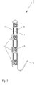
- FIG. 1 shows the front of an operating unit 1 with a breakthrough-free one continuous control surface 2, made of glass or glass-like material.
- actuation areas 3 are arranged on the control surface 2 .
- pressure-sensitive sensors 4 i. H. Piezo sensors 4, e.g. Piezo disks Type BCE from Sanyo, preferably behind the operating surface 2 in a matrix are arranged.
- actuation areas 3 Assigned to the actuation areas 3 is a printed film 5 with symbols attached for the functions 6 per actuation area 3. This slide 5 is behind the glass control surface 2.
- the piezo sensors 4 are preferably offset from the symbols of the printed film 5 or operating areas 3 of the control surface 2 arranged so that by means of a light source 7, for example a light guide or light stone, which printed Slide 5 is illuminated directly. If the light from the light source 7 is to illuminate the film 5, so the film 5 must be translucent.
- the control surface 2 is in a conventional manner by a metal frame 8 (Fig. 2 a / b) attached to a household appliance, not shown, for example stove. This can be in an upper section, for example above the baking and Roasting oven door done. A separate attachment of the control surface 2 outside the Large device is possible.
- FIG. 2 b and FIG. 3 there is a film package 9 with the integrated piezo sensors 4 behind the operating surface 2.
- the film package 9 is electrical via a flexible connector 10 with a printed circuit board 11, which is functionally assigned to a processor 12 connected.
- the film package 9 consists in one part of a front and a rear film, but can also be constructed from a front film and a cover film, connected by a loop.
- Printed conductors that electrically connect the flexible connector 10 and the piezo sensors 4 are applied to these foils.
- the film package has a spacer film 14 (spacer film) lying between the films.
- the light source 7 required for light distribution is preferably on the printed circuit board 11 arranged with.
- the symbols of the functions 6 on the film are on the film package 9 5 printed (Fig. 3).
- the pressure-sensing piezo sensors 4 which have contacts 13, conductor tracks and the connector 10 are electrically connected to the circuit board 11.
- the contacting 13 of the piezo sensors 4 takes place via the two sensor surfaces with the front film and the rear film of the film package 9.
- the piezo sensors 4 are preferably glued into the foil package 9, using an electrical contact adhesive (Conductive adhesive) takes over the contact 13.
- Spacer film 14 provides the necessary distance or for the compensation for height adjustment in the foil package 9.
- the spacer foil 14 is used for positioning of the piezo sensors 4.
- the punched holes in the spacer film 14 result from the required arrangement of the piezo sensors 4 in the foil package 9 and are by the in the control unit 1 of the household appliance provided arrangement of the symbols of Functions 6 specified.
- the foil package 9 is preferred in the areas where there are no piezo sensors 4 translucent so that the light from the light sources 7 the printed film 5th illuminated in the symbol area.
- the foil package 9 is insolubly rigidly connected to the rear of the control surface 2 and introduces the pressure pulses directly to the piezo sensors, ie does not dampen them.
- the piezo sensors 4 can also be attached directly to the rear of the control surface 2 by a conductive adhesive and carried by this control surface.
- Fig. 4 shows schematically the functional sequence. If an operator touches the control surface 2, this control surface 2 bends at the actuation position / area 3.
- a piezo sensor 4 located behind it for example an inversely operating piezo buzzer, a potential difference is generated in a known manner via a charge shift in the piezo sensor 4, as a result of which a signal (voltage pulse) is supplied by the piezo sensor 4.
- This signal consists of two opposite pulses, which are caused once when the force is applied and the other time when the force is released.
- the amplitude of the pulses depends on the size / strength the pressure change on the control surface 2, from the removal of the pressure in Actuation range 3 to the piezo sensor 4 and the piezoelectric coefficient of Piezo sensor 4 itself.
- the sensor signal generated by the piezo sensor 4 arrives into the processor 12 and is passed through an input filter 15.
- the input filter 15 is set to a frequency of preferably 1 Hz for fast unconscious operations on the actuation area 3, for example when cleaning the control surface 2, the are picked up and passed on by the piezo sensors 4, not for evaluation bring to.
- the analog sensor signals passing through the input filter 15 become conventional ones Switching stages in processor 12, for example, by an A / D converter, digital Signals generated by a microcontroller 16 through a defined software be evaluated.
- the microcontroller 16 determines which piezo sensor 4 was activated by actuation.
- the software program also checks the switching state of this called, assigned to the actuated piezo sensor 4 Function 6, d. H. whether function 6 is switched on or off should. This enables the use of only one piezo sensor 4 for switching on or off a function 6.
- function 6 "oven” determines the microcontroller 16 after this with the actuated piezo sensor 4 the associated function 6 has determined the function state (on / off) and controls the light source 7 associated with the function 6 "oven” behind the control surface 2 and a power section 17 of the cooker for switching the oven on or off.
- the lighting changes color behind the printed film (s) 5 as search lighting.
- the one that is printed Illuminating film 5 light source 7 switched, for example from red to green, for example with a well-known two-color LED.
- An additional display 18, for example A graphic Liquid Cristal Display (LCD) can be placed in the area of the cooker be appropriate and display different values in a conventional manner.
- LCD graphic Liquid Cristal Display
- control surface 2 has a number of matrix-like pressure-sensing piezo sensors 4, the force when pressing an actuation area 3 of the function 6, for example 'grill 1' by others Piezo sensors 4 of the other functions 6, for example 'grill 2' and 'baking' detected and also leads to a voltage pulse there. These pulses take in their amplitude from, the further the piezo sensors 4 are from the actuated actuation area 3.
- the one closest to the pressure area of control surface 2 Piezo sensor 4 delivers the quantitatively strongest signal U1, the neighboring piezo sensors 4 quantitatively lower signals U2 (Fig. 5). All signals U1, U2 generated in this way are given to the microcontroller 16 via the input filter 15.
- control unit 1 is used also a control of the power section 17 of the cooker, for example the control of the Function 6 'Temperature in the oven'. This is done via a piezo sensor 4 for up-regulation (+) the temperature and a further piezo sensor 4 for regulating / controlling (-) temperature realized.
- the set temperature is displayed in the known display 18, not shown, of the display 18. Overriding the temperature, for example> 250 ° C, in the oven is excluded by software. When the temperature is reduced, the two pulses are also determined after the pressure has been applied to the piezo sensor 4 to regulate the temperature, the time in between is measured and this is filled with counting pulses from the software of the processor 12 in the same way as the temperature increase, with a defined temperature decrease per counting pulse.
- These piezo sensors 4, which control the function 6, can also switch on and off of the oven.
- that on the piezo sensor 4 is used Adjusting the temperature generates a pulse when the pressure is applied to the control surface 2 used as a positive pulse to switch on.
- the invention is within the scope of its claims and its The basic idea is changeable. This can be done using suitable hardware and / or software an additional security check is carried out. This applies in particular to one Childproof lock or a lock against multiple actuation. It is also possible that the sensors 4 frame the control panel 2, so that a matrix-like arrangement the sensors are omitted. Likewise, the sensors 4 can be directly under the printed film 5 be arranged so that the light source 7 is slightly offset from the film 5.
- An integral evaluation of the signal areas (FIG. 5) of the sensor signals by the processor 12 makes it easier to distinguish between wanted and random, i.e. unwanted Operation of the control surface 2.
- An older person becomes when the control surface is operated intentionally 2 exert only a small pressure to trigger a function 6, however for a long time. The pressure variation over a long time creates one correspondingly large integral area of the sensor signal.
- one becomes comparable low pressure form a correspondingly small integral area over a short time, which does not trigger function 6. The latter arises e.g. when cleaning the control surface 2 by wiping in the operating area 3.
- the control unit 1 can be easily adapted to the requirements of different household appliances. All that is required is a correspondingly functional design of the Processor 12 and if necessary a reorientation of the function symbols on the Control surface 2.
Abstract
Description
Die Erfindung betrifft eine Bedieneinheit zum Schalten und Steuern von Haushaltsgeräten,
insbesondere Haushaltsgroßgeräten, wie zum Beispiel Küchenherden, Spül- und
Waschmaschinen und dergleichen, nach dem Oberbegriff des Patentanspruchs 1.
Außerdem betrifft die Erfindung ein Verfahren nach dem Oberbegriff des Patentanspruchs
14.The invention relates to an operating unit for switching and controlling household appliances,
in particular large household appliances, such as kitchen stoves, dishwashers and
Washing machines and the like, according to the preamble of
Eine Bedieneinheit (Bedienungstableau) beschreibt die DE 39 20 257 A1. Dabei weist das Bedienungstableau Bedienungselemente und diesen entsprechend zugeordnete Anzeigeelemente auf. Durch die Verwendung von Bedienungstasten ist die Bedienfläche im Betätigungsbereich durchbrochen und schwer zu reinigen.An operating unit (control panel) is described in DE 39 20 257 A1. It points the control panel control elements and correspondingly assigned display elements on. By using control buttons the control surface is Openwork in the operating area and difficult to clean.
Die DE 42 29 731 A1 beschreibt ein Bedienungsfeld, das in einem Einbaugehäuse mit einer Abdeckplatte untergebracht ist. Dabei sind die Anzeige- und/oder Bedienungselemente des Bedienfeldes auf der Innenseite der Abdeckplatte angeordnet. Ein Schalten und Steuern des Haushaltsgerätes kann zusätzlich über eine Infrarotfernbedienung erfolgen. Auch hier sind als Bedienungselemente Tasten angegeben.DE 42 29 731 A1 describes a control panel that is included in an installation housing a cover plate is housed. The display and / or control elements the control panel on the inside of the cover plate. Turn on and control of the household appliance can also be done via an infrared remote control. Here, too, keys are specified as operating elements.
Eine Sensorschalteinrichtung gibt die DE 4407 741 A1 an. Hierbei wird zum Ein- oder Ausschalten zusätzlich zu den Bedientasten ein Mikroprozessor für die Zu- oder Abschaltung eines Leistungsteils, beispielsweise einer Warmhalteplatte im Kochfeld eines Herdes mit einbezogen. Aus Sicherheitsgründen sind für das Zuschalten des Leistungsteiles zwei Bedientasten in zeitlicher Reihenfolge zu betätigen.A sensor switching device specifies DE 4407 741 A1. Here is the on or In addition to the control buttons, a microprocessor can be switched on or off a power section, for example a hot plate in the cooktop Herd included. For safety reasons are for switching on the power section to operate two control buttons in chronological order.
Der US 4,190,785 ist ein druckempfindlicher Signalgenerator entnehmbar. In Sandwichform ist dabei eine piezoelektrische Schicht zwischen einem elektrischen leitenden Substrat bzw. Trägermaterial und Elektroden angebracht. Die piezoelektrische Schicht ist über die gesamte Unterfläche des Substrats aufgetragen. Auf dem Substrat befinden sich an vorgegebenen Stellen aufgesetzte Druckpunkte in Form von Pads, wobei jedem Druckpunkt eine unterhalb der piezoelektrischen Schicht angeordnete Elektrode zugeordnet ist. Bei Druckwirkung auf ein Pad verändert sich die Ausgangsspannung zwischen dem Substrat und der jeweiligen Elektrode. Dabei ist für jedes Pad eine Ausgangsspannung definiert, so daß durch einen Soll-Ist-Vergleich im Signalprozessor die Druckenwirkstelle ermittelt wird. Ein Greifen neben die Pads bewirkt für den Signalprozessor undefinierbare Zustände, so daß Fehlbedienungen auftreten können.A pressure-sensitive signal generator can be found in US Pat. No. 4,190,785. In sandwich form is a piezoelectric layer between an electrically conductive Substrate or carrier material and electrodes attached. The piezoelectric layer is applied over the entire lower surface of the substrate. Are on the substrate pressure points in the form of pads placed at predetermined points, each Pressure point assigned to an electrode arranged below the piezoelectric layer is. When pressure is applied to a pad, the output voltage changes between the substrate and the respective electrode. There is an output voltage for each pad defined, so that the actual pressure point by a target-actual comparison in the signal processor is determined. A grasp next to the pads causes indefinable for the signal processor States so that operating errors can occur.
Die Aufgabe der Erfindung besteht darin, eine Bedieneinheit zum Schalten und Steuern eines Haushaltsgerätes anzugeben, deren Bedienfläche im Betätigungsbereich frei von Durchbrüchen ist, die hinsichtlich ihrer Betätigungsposition mit einfachen Mitteln entsprechend den Erfordernissen unterschiedlicher Geräte gestaltbar ist und die Fehlbedienungen erschwert.The object of the invention is a control unit for switching and controlling specify a household appliance, the control surface in the operating area free of Breakthroughs is the corresponding in terms of their operating position with simple means the requirements of different devices can be designed and the incorrect operation difficult.
Gelöst wird die Aufgabe durch die kennzeichnenden Merkmale des Patentanspruchs 1
sowie des Patentanspruchs 14.The object is achieved by the characterizing features of
Der Erfindung liegt dabei die Idee zugrunde, einzelne Piezosensoren zur Aktivierung von Funktionen zu verwenden. Mit Hilfe eines Prozessors werden die von den Piezosensoren erzeugten Signale ausgewertet und je nach Funktionswahl an ein Leistungsteil zum Schalten der gewählten Funktion durchgeschaltet. Die bei kurzen ungewollten Druckeinwirkungen auf die Piezosensoren ausgelösten Signale werden im Prozessor ausgefiltert. Dadurch wird eine Fehlbedienung erschwert, da ein bewußt aufgebrachter Druck oder eine längere Druckperiode zur Schaltung und Steuerung des Haushaltsgerätes erforderlich ist. Die Übertragung des Betätigungsdruckes auf die Piezosensoren erfolgt durch die geschlossene, an sich steife Bedienfläche hindurch, die dicht und somit einfach zu reinigen ist.The invention is based on the idea of individual piezo sensors for activating Functions to use. With the help of a processor, those from the piezo sensors generated signals evaluated and depending on the function selection to a power unit Switching the selected function through. The in the case of brief unwanted pressure effects Signals triggered on the piezo sensors are filtered out in the processor. This makes it difficult to operate incorrectly, as deliberately applied pressure or a longer printing period is required to switch and control the household appliance is. The actuation pressure is transmitted to the piezo sensors through the closed, stiff operating surface, which is tight and therefore simple is to be cleaned.
Vorteilhafte Ausführungen sind in den Unteransprüchen enthalten.Advantageous designs are contained in the subclaims.
Die Piezosensoren befinden sich hinter einer Bedienfläche, die für optische Signale aus transparentem Material, vorzugsweise aus Glas aber auch aus einem anderen formstabilen Material, z.B. Metall, Kunststoff, Holz bestehen kann. Diese Bedienfläche kann frontseitig und bei glasartigem Material auch rückseitig mit Symbolen bedruckt sein und dient als Berührungsfläche für den Benutzer.The piezo sensors are located behind a control surface that is used for optical signals transparent material, preferably made of glass but also of another dimensionally stable Material, e.g. Metal, plastic, wood can exist. This control surface can be on the front and with glass-like material can also be printed on the back with symbols and serves as a contact surface for the user.
Durch die Verwendung einer zumindest in den Betätigungsbereichen durchbruchfreien, durchgehenden Bedienfläche sind die dahinterliegenden Bauteile gegen Umwelteinflüsse wie beispielsweise Staub und Feuchtigkeit geschützt.By using a breakthrough-free, at least in the operating areas, continuous control surface are the components behind it against environmental influences such as dust and moisture.
Vorteilhaft ist ein versetztes Aufbringen der Sensoren zum jeweiligen Betätigungsbereich der Bedienfläche, da dieser mit den Funktionssymbolen bedruckte Betätigungsbereich direkt mittels einer Lichtquelle durchleuchtet werden kann. Auch wird mit der Verwendung von mehreren Sensoren, zugehörig zu einem Betätigungsbereich und damit zu einer Funktion erreicht, daß eine eindeutige Zuordnung (Aussage) für die ausgewählte Funktion durch den Prozessor erhalten wird, auch wenn nur in der Nähe des Betätigungsbereiches der Druck aufgebracht wurde.An offset application of the sensors to the respective actuation area is advantageous the operating area, since this area is printed with the function symbols can be examined directly by means of a light source. Also, with use of several sensors belonging to one actuation area and thus to A function achieves that a clear assignment (statement) for the selected Function is maintained by the processor, even if only in the vicinity of the operating area the pressure was applied.
Die Sensoren selbst sind vorzugsweise in einem Folienpaket untergebracht, wobei die Sensoroberflächen vorteilhaft direkt mit Leiterbahnen einer inneren Vorder- und einer inneren Rückseite der Folie mittels Kontaktkleber kontaktiert sind. Dies bewirkt einen einfachen Aufbau des Folienpakets und eine gute mechanische Fixierung der Sensoren und der bedruckten Folien an der Rückseite der Bedienfläche bei der Fertigung des Haushaltsgerätes zur indirekten Verbindung zwischen den Sensoren und der Bedienfläche. Die Sensoren können aber auch direkt mittels einem Kleber oder Leitkleber an der Rückseite der Bedienfläche angebracht sein.The sensors themselves are preferably housed in a foil package, the Sensor surfaces advantageously directly with conductor tracks of an inner front and one inner back of the film are contacted with contact adhesive. This results in a simple construction of the foil package and a good mechanical fixation the sensors and the printed foils on the back of the control surface at the Manufacture of the household appliance for the indirect connection between the sensors and the control surface. The sensors can also be used directly with an adhesive or conductive adhesive be attached to the back of the control surface.
Wesentlich ist, daß die Piezosensoren starr bzw. fest mit der Bedienfläche verbunden sind. Die vorzugsweise matrixartig verteilten Piezosensoren erfassen bereits geringste Durchwölbungen der Bedienfläche.It is essential that the piezo sensors are rigidly or firmly connected to the control surface are. The piezo sensors, which are preferably distributed in a matrix-like manner, already detect the smallest Bulges in the control surface.
Anhand eines Ausführungsbeispieles mit Zeichnung soll die Erfindung näher erläutert werden. The invention is to be explained in more detail using an exemplary embodiment with a drawing will.
Es zeigen:
eine Draufsicht auf eine Bedienfläche einer Bedieneinheit eines Haushaltsgerätes,
eine schematische Seitenansicht der Bedienfläche in eingebautem Zustand,
ein Folienpaket mit Sensoren,
ein Blockschaltbild des Funktionsablaufes,
gemessene Signalverläufe an benachbarten Sensoren,
a plan view of an operating surface of an operating unit of a household appliance,
a schematic side view of the control surface in the installed state,
a foil package with sensors,
a block diagram of the functional sequence,
measured signal curves at neighboring sensors,
In Fig. 1 dargestellt ist die Frontseite einer Bedieneinheit 1 mit einer durchbruchfreien
durchgehenden Bedienfläche 2, aus Glas oder glasähnlichem Material. Auf der Bedienfläche
2 sind Betätigungsbereiche 3 angeordnet. In Zuordnung zu diesen Betätigungsbereichen
3 befinden sich druckempfindliche Sensoren 4, d. h. Piezosensoren 4, z.B. Piezoscheiben
Typ BCE der Fa. Sanyo, die hinter der Bedienfläche 2 vorzugsweise matrixartig
angeordnet sind.1 shows the front of an
In Zuordnung zu den Betätigungsbereichen 3 ist eine bedruckte Folie 5 mit Symbolen
für die Funktionen 6 je Betätigungsbereich 3 angebracht. Diese Folie 5 befindet sich hinter
der Glasbedienfläche 2.Assigned to the
Vorzugsweise sind die Piezosensoren 4 versetzt zu den Symbolen der bedruckten Folie
5 beziehungsweise Betätigungsbereichen 3 der Bedienfläche 2 angeordnet, so daß mittels
einer Lichtquelle 7, beispielsweise einem Lichtleiter oder Lichtstein, die bedruckte
Folie 5 direkt beleuchtet wird. Soll das Licht der Lichtquelle 7 die Folie 5 durchleuchten,
so muß die Folie 5 lichtdurchlässig sein. The
Die Bedienfläche 2 wird in herkömmlicher Art und Weise durch einen Metallrahmen 8
(Fig. 2 a/b) an einem nicht näher dargestellten Haushaltsgerät, beispielsweise Herd, befestigt.
Dies kann in einem oberen Teilbereich, beispielsweise oberhalb der Back- und
Bratofentür erfolgen. Auch eine separate Anbringung der Bedienfläche 2 außerhalb des
Großgerätes ist möglich.The
Wie in Fig. 2 b und Figur 3 schematisch dargestellt, befindet sich hinter der Bedienfläche
2 ein Folienpaket 9 mit den integrierten Piezosensoren 4. Das Folienpaket 9 ist über
einen flexiblen Verbinder 10 mit einer Leiterplatte 11, die einem Prozessor 12 funktionell
zugeordnet ist, elektrisch verbunden.
Das Folienpaket 9 besteht einteilig aus einer vorderen und einer hinteren Folie, kann
aber auch, über eine Schlaufe verbunden, aus einer Frontfolie und einer Abdeckfolie
aufgebaut sein. Auf diesen Folien aufgebracht sind Leiterbahnen, die den flexiblen Verbinder
10 und die Piezosensoren 4 elektrisch verbinden. Zudem weist das Folienpaket
eine zwischen den Folien liegende Spacerfolie 14 (Abstandsfolie) auf.As shown schematically in FIG. 2 b and FIG. 3, there is a film package 9 with the integrated
The film package 9 consists in one part of a front and a rear film, but can also be constructed from a front film and a cover film, connected by a loop. Printed conductors that electrically connect the
Auf der Leiterplatte 11 ist vorzugsweise die zur Lichtverteilung benötigte Lichtquelle 7
mit angeordnet. Auf dem Folienpaket 9 sind die Symbole der Funktionen 6 auf die Folie
5 gedruckt (Fig. 3). Im Folienpaket 9 zwischen der vorderen und der hinteren Folie befinden
sich die druckaufnehmenden Piezosensoren 4, die über Kontakte 13, Leiterbahnen
und dem Verbinder 10 mit der Leiterplatte 11 elektrisch verschaltet sind. Die Kontaktierung
13 der Piezosensoren 4 erfolgt über die beiden Sensoroberflächen mit der
vorderen Folie und der hinteren Folie des Folienpaketes 9. Die Piezosensoren 4 sind
vorzugsweise in das Folienpaket 9 eingeklebt, wobei ein elektrischer Kontaktkleber
(Leitkleber) die Kontaktierung 13 übernimmt. Die an entsprechenden Stellen ausgestanzte
Spacerfolie 14 sorgt für den erforderlichen Abstand bzw. für den Ausgleich zur Höhenanpassung
im Folienpaket 9. Gleichzeitig dient die Spacerfolie 14 zur Positionierung
der Piezosensoren 4. Die Ausstanzungen in der Spacerfolie 14 ergeben sich durch die
erforderliche Anordnung der Piezosensoren 4 im Folienpaket 9 und werden durch die in
der Bedieneinheit 1 des Haushaltsgerätes vorgesehenen Anordnung der Symbole der
Funktionen 6 vorgegeben. The
Das Folienpaket 9 ist in den Bereichen, wo sich keine Piezosensoren 4 befinden, vorzugsweise
lichtdurchlässig, so daß das Licht aus den Lichtquellen 7 die bedruckte Folie 5
im Symbolbereich durchleuchtet.The foil package 9 is preferred in the areas where there are no
Eine wesentliche Voraussetzung für das Funktionieren der Bedieneinheit 1 ist, daß das
Folienpaket 9 unlöslich starr mit der Rückseite der Bedienfläche 2 verbunden ist und die
Druckimpulse direkt auf die Piezosensoren einleitet, d.h. nicht dämpft.
Die Piezosensoren 4 können auch unmittelbar an der Rückseite der Bedienfläche 2
durch einen Leitkleber befestigt und von dieser Bedienfläche getragen sein.An essential prerequisite for the operation of the
The
Fig. 4 stellt schematisch den Funktionsablauf dar.
Wird durch eine Bedienperson die Bedienfläche 2 berührt, tritt eine Verbiegung dieser
Bedienfläche 2 an der Betätigungsposition/-bereich 3 auf. In einem dahinter liegenden
Piezosensor 4, beispielsweise einem invers arbeitenden Piezosummer, wird über eine
Ladungsverschiebung im Piezosensor 4 in bekannter Art und Weise eine Potentialdifferenz
erzeugt, wodurch ein Signal (Spannungspuls) von dem Piezosensor 4 geliefert wird.
Diese Signal besteht aus zwei im Vorzeichen entgegengesetzten Pulsen, die einmal
beim Einleiten der Kraft und das andere mal beim Lösen der Kraft hervorgerufen werden.Fig. 4 shows schematically the functional sequence.
If an operator touches the
Die Amplitude der Pulse ist bei gegebener Schaltung abhängig von der Größe/Stärke
der Druckänderung auf die Bedienfläche 2, von der Entfernung der Druckeinwirkung im
Betätigungsbereich 3 zum Piezosensor 4 und vom piezoelektrischen Koeffizienten des
Piezosensors 4 selbst. Prinzipiell gelangt das vom Piezosensor 4 erzeugte Sensorsignal
in den Prozessor 12 und wird über einen Eingangsfilter 15 geführt. Der Eingangsfilter 15
ist auf eine Frequenz von vorzugsweisen 1 Hz eingestellt, um schnelle unbewußte Betätigungen
am Betätigungsbereich 3, beispielsweise beim Reinigen der Bedienfläche 2, die
von den Piezosensoren 4 aufgenommen und weitergegeben werden, nicht zur Auswertung
zu bringen.For a given circuit, the amplitude of the pulses depends on the size / strength
the pressure change on the
Aus den, den Eingangsfilter 15 passierenden, analogen Sensorsignalen werden über herkömmliche
Schaltstufen im Prozessor 12 beispielsweise durch einen A/D-Wandler, digitale
Signale erzeugt, die von einem Mikrocontroller 16 durch eine definierte Software
ausgewertet werden. Durch das Softwareprogramm stellt der Mikrocontroller 16 fest,
welcher Piezosensor 4 durch Betätigung angesprochen wurde. Zudem prüft das Softwareprogramm
den Schaltzustand dieser aufgerufenen, dem betätigten Piezosensor 4 zugeordneten
Funktion 6, d. h. ob die Funktion 6 zugeschaltet oder abgeschaltet werden
soll. Dies ermöglicht die Verwendung nur eines Piezosensors 4 zum Ein- oder Ausschalten
einer Funktion 6. Soll beispielsweise die Funktion 6 "Backofen" eingeschalten werden,
ermittelt der Mikrocontroller 16, nachdem dieser den betätigten Piezosensor 4 mit
der dazugehörigen Funktion 6 ermittelt hat, den Funktionszustand (Ein/Aus) und steuert
die zur Funktion 6 " Backofen" zugehörige Lichtquelle 7 hinter der Bedienfläche 2 sowie
ein Leistungsteil 17 des Herdes zum Ein- oder Ausschalten des Backofens an. Zur optischen
Anzeige der ausgewählten Funktion 6 erfolgt ein Farbumschlag der Beleuchtung
hinter der/den bedruckten Folien 5 als Suchbeleuchtung. Dazu wird die, die bedruckte
Folie 5 ausleuchtende, Lichtquelle 7 umgeschaltet, beispielsweise von rot in grün, beispielsweise
durch eine bekannte Zwei-Farben-LED. Eine zusätzliche Anzeige 18 beispielsweise
ein graphisches Liquid Cristal Display (LCD) kann im Bereich des Herdes
angebracht sein und in herkömmlicher Art und Weise verschiedene Werte anzeigen.The analog sensor signals passing through the
Da die Bedienfläche 2 an ihrer Rückseite mehrere dahinterliegende, matrixartig angeordnete,
druckaufnehmende Piezosensoren 4 aufweist, wird die Kraft beim Drücken auf
einen Betätigungsbereich 3 der Funktion 6, beispielsweise 'Grill 1' auch durch andere
Piezosensoren 4 der anderen Funktionen 6, beispielsweise 'Grill 2' und 'Backen' erkannt
und führt auch dort zu je einem Spannungspuls. Diese Pulse nehmen in ihrer Amplitude
ab, je weiter sich die Piezosensoren 4 vom betätigten Betätigungsbereich 3 entfernt befinden.
Der am nächsten im druckeinwirkenden Bereich der Bedienfläche 2 liegende
Piezosensor 4 liefert das quantitativ stärkste Signal U1, die benachbarten Piezosensoren
4 quantitativ geringere Signale U2 (Fig. 5). Alle so erzeugten Signale U1, U2 werden
über den Eingangsfilter 15 an den Mikrocontroller 16 gegeben. Dabei gelangen alle benachbarten
Sensorsignale U2 zur Ansteuerung an den Mikrocontrolle 16 und werden
vom Mikrocontoller 16 zur Auswertung der Funktionsauswahl berücksichtigt. Die Abfrage
der exakten Funktionsauswahl 6 erfolgt durch die Auswertung der Amplitude der Pulse
und damit der Signalstärke, die die matrixartig angeordneten Piezosensoren 4 erzeugen.
Ein im Mikrocontroller 16 hinterlegtes Muster stellt diese matrixartige Anordnung
der Piezosensoren 4 durch eine interne Speicherberechnung im Prozessor 12 nach, so
daß durch die zeilen- und spaltenartige Zuordnung der Piezosensor 4 im Muster mit der
größten Amplitude ermittelt, dem betätigten Piezosensoren 4 zugeordnet und damit die
ausgewählte Funktion 6 bestimmt wird. Die technische Realisierung erfolgt durch das
Softwareprogramm.Since the
Es hat sich gezeigt, daß schon Durchbiegungen von wenigen µm (2 bis 5), die sich beim
Betätigen der Bedienfläche 2 im Betätigungsbereich 3 an der Bedienfläche 2 ergeben,
hinreichend auswertbare Signale U1, U2 der Piezosensoren 4 bewirken. Dabei erzeugt
der dem Druckpunkt nächstliegende Piezosensor 4, wie bereits beschrieben, ein größeres
Spannungssignal U1 als entferntere Piezosensoren 4. Dieser Umstand wird vom Prozessor
12 zur Identifizierung und Auslösung einer Funktion 6 genutzt. Gleiches gilt beim
Vorliegen mehrerer gleichgroßer Signale in Relation zu geringeren Signalen der übrigen
Piezosensoren 4.It has been shown that even deflections of a few microns (2 to 5), which are in the
Operating the operating
Neben dem bereits beschriebenen Ein- und Ausschalten erfolgt über die Bedieneinheit 1
auch eine Steuerung des Leistungsteils 17 des Herdes, beispielsweise die Steuerung der
Funktion 6 'Temperatur im Backofen'. Dies wird über einen Piezosensor 4 zum Hochregeln
(+) der Temperatur und über einen weiteren Piezosensor 4 zum Abregeln/-steuern
(-) der Temperatur realisiert.In addition to the switching on and off as already described, the
Dazu werden der am Piezosensor 4 zum Hochregeln/-steuern der Temperatur erzeugte
Puls beim Einleiten der Druckkraft auf die Bedienfläche 2 als positiver Puls und der beim
Lösen der Druckkraft erzeugte negative Puls gemessen und eine zwischen positiven und
negativen Puls liegende Zeit ermittelt. Diese dazwischen liegende Zeitdauer (Δ t) wird
durch das Softwareprogramm mittels Zählimpulsen gefüllt, wobei pro Zählimpuls eine
durch die Software zugeordnet, definierte Temperaturerhöhung erfolgt.For this purpose, those generated on the
Die Anzeige der eingestellten Temperatur erfolgt im nicht näher dargestellten bekannten
Anzeigedisplay der Anzeige 18.
Eine Übersteuerung der Temperatur, beispielsweise >250 ° C ,im Backofen wird softwaremäßig
ausgeschlossen.
Bei Temperaturreduzierung werden nach Druckeinleitung auf den Piezosensor 4 zum
Abregeln der Temperatur die beiden Pulse gleichfalls ermittelt, die Zeit dazwischen gemessen
und diese analog zur Temperaturerhöhung mit Zählimpulsen der Software des
Prozessors 12 gefüllt, wobei pro Zählimpuls eine definierte Temperatursenkung erfolgt.The set temperature is displayed in the known
Overriding the temperature, for example> 250 ° C, in the oven is excluded by software.
When the temperature is reduced, the two pulses are also determined after the pressure has been applied to the
Diese, die Funktion 6 steuernden Piezosensoren 4, können auch das Zu- und Abschalten
des Backofens übernehmen. Dazu wird beispielsweise der an dem Piezosensor 4 zum
Hochregeln der Temperatur erzeugte Puls beim Einleiten der Druckkraft auf die Bedienfläche
2 als positiver Puls zum Einschalten genutzt.These
Zur Erhöhung des Bedienkomforts ist es möglich, einer Funktion 6 und damit einem Betätigungsbereich
3 mehrere Piezosensoren 4 zuzuordnen, so daß eine exaktere Auswertung
der ausgewählten Funktion 6 erfolgen kann. Die Auswertung erfolgt in beschriebener
Art und Weise im Prozessor 12.To increase the ease of use, it is possible to use a
Es versteht sich von selbst, daß die Erfindung im Rahmen ihrer Ansprüche und ihres
Grundgedankens abänderbar ist. So kann durch eine geeignete Hard- und/oder Software
eine zusätzliche Sicherheitsüberprüfung erfolgen. Dies betrifft insbesondere eine
Kindersicherung oder eine Verriegelung gegen Mehrfachbetätigung. Auch ist es möglich,
daß die Sensoren 4 das Bedienfeld 2 umrahmen, so daß eine matrixartige Anordnung
der Sensoren entfällt. Ebenso können die Sensoren 4 direkt unter der bedruckten Folie 5
angeordnet sein, so daß die Lichtquelle 7 leicht versetzt zu der Folie 5 angeordnet ist.It goes without saying that the invention is within the scope of its claims and its
The basic idea is changeable. This can be done using suitable hardware and / or software
an additional security check is carried out. This applies in particular to one
Childproof lock or a lock against multiple actuation. It is also possible
that the
Eine integrale Auswertung der Signalflächen (Fig. 5) der Sensorsignale durch den Prozessor
12 erleichtert eine Unterscheidung von gewollten und zufälligen, d.h. ungewollter
Betätitung der Bedienfläche 2. Eine ältere Person wird bei gewollter Betätigung des Bedienfläche
2 zur Auslösung einer Funktion 6 einen nur geringen Druck ausüben, jedoch
über eine längere Zeit. Die Druckvariation über eine längere Zeit hinweg erzeugt eine
entspreched große Integralfläche des Sensorsignales. Dagegen wird ein vergleichbar
geringer Druck über eine kurze Zeit eine entsprechend kleine Integralfläche ausbilden,
die keine Funktion 6 auslöst. Letzteres entsteht z.B. beim Reinigen der Bedienfläche 2
durch Überwischen im Betätigungsbereich 3.An integral evaluation of the signal areas (FIG. 5) of the sensor signals by the
Die Bedieneinheit 1 ist den Erfordernissen unterschiedlicher Hauhaltsgeräte leicht anzupassen.
Hierzu bedarf es lediglich eine entsprechend funktionelle Ausgestaltung des
Prozessors 12 und bedarfsweise eine Umorientierung der Funktions-Symbole auf der
Bedienfläche 2.The
Claims (17)
Applications Claiming Priority (2)
| Application Number | Priority Date | Filing Date | Title |
|---|---|---|---|
| DE19645678 | 1996-11-06 | ||
| DE19645678A DE19645678C2 (en) | 1996-11-06 | 1996-11-06 | Control unit for switching and controlling household appliances |
Publications (3)
| Publication Number | Publication Date |
|---|---|
| EP0841521A2 true EP0841521A2 (en) | 1998-05-13 |
| EP0841521A3 EP0841521A3 (en) | 2000-05-10 |
| EP0841521B1 EP0841521B1 (en) | 2002-11-13 |
Family
ID=7810768
Family Applications (1)
| Application Number | Title | Priority Date | Filing Date |
|---|---|---|---|
| EP97116612A Expired - Lifetime EP0841521B1 (en) | 1996-11-06 | 1997-09-24 | Operating unit for switching and controlling household appliances |
Country Status (3)
| Country | Link |
|---|---|
| US (1) | US5995877A (en) |
| EP (1) | EP0841521B1 (en) |
| DE (2) | DE19645678C2 (en) |
Cited By (8)
| Publication number | Priority date | Publication date | Assignee | Title |
|---|---|---|---|---|
| EP1045300A2 (en) * | 1999-04-16 | 2000-10-18 | Preh-Werke GmbH & Co. KG | Operating element for switching and controlling electrically operated devices with a screen |
| WO2003081411A2 (en) * | 2002-03-12 | 2003-10-02 | BSH Bosch und Siemens Hausgeräte GmbH | Touch panel |
| WO2009003716A1 (en) * | 2007-07-04 | 2009-01-08 | Aquis Sanitär AG | Actuating device for controlling a water fitting |
| EP2101111A1 (en) * | 2008-03-07 | 2009-09-16 | BSH Bosch und Siemens Hausgeräte GmbH | Contol device for a domestic appliance |
| EP2192350A1 (en) * | 2008-11-15 | 2010-06-02 | Electrolux Home Products Corporation N.V. | A control panel for controlling several different functions of an appliance |
| EP2564751A1 (en) * | 2011-08-27 | 2013-03-06 | Diehl AKO Stiftung & Co. KG | Control panel for an electric device |
| EP2775624A1 (en) * | 2013-03-08 | 2014-09-10 | Delta Electronics, Inc. | Switch control module with piezoelectric element and electric device employing same |
| EP3023834A1 (en) * | 2014-11-18 | 2016-05-25 | E.G.O. ELEKTRO-GERÄTEBAU GmbH | Operating device for an electrical device and electrical device |
Families Citing this family (38)
| Publication number | Priority date | Publication date | Assignee | Title |
|---|---|---|---|---|
| DE19814446A1 (en) * | 1998-03-31 | 1999-10-07 | Bosch Siemens Hausgeraete | Program-controlled household appliance |
| US6061602A (en) | 1998-06-23 | 2000-05-09 | Creative Lifestyles, Inc. | Method and apparatus for developing application software for home automation system |
| US7754025B1 (en) | 2000-06-08 | 2010-07-13 | Beverage Works, Inc. | Dishwasher having a door supply housing which holds dish washing supply for multiple wash cycles |
| US7083071B1 (en) | 2000-06-08 | 2006-08-01 | Beverage Works, Inc. | Drink supply canister for beverage dispensing apparatus |
| DE10064118A1 (en) * | 2000-12-21 | 2002-06-27 | Bsh Bosch Siemens Hausgeraete | Electrically operated household appliance |
| DE10133135C5 (en) | 2001-07-07 | 2012-11-15 | Electrolux Professional Ag | Setting unit for cooking appliances |
| NZ540885A (en) * | 2002-12-20 | 2009-02-28 | Chakshu Res Inc | Ophthalmic formulation for the prevention and treatment of ocular conditions |
| DE10311447B4 (en) * | 2003-03-15 | 2007-06-06 | Schott Ag | Circuit arrangement for an electrical appliance |
| WO2005060814A1 (en) * | 2003-12-22 | 2005-07-07 | BSH Bosch und Siemens Hausgeräte GmbH | Dishwasher with controller device |
| DE102004005952A1 (en) * | 2004-02-02 | 2005-08-25 | E.G.O. Elektro-Gerätebau GmbH | Operating device for an electrical appliance with a control panel and a sensor element underneath and method for operating the operating device |
| DE102004005954A1 (en) * | 2004-02-02 | 2005-08-18 | E.G.O. Elektro-Gerätebau GmbH | Operating device for an electrical appliance with a control panel and a sensor element underneath and method for operating the operating device |
| US20050183469A1 (en) * | 2004-02-25 | 2005-08-25 | Kang Dong W. | Control panel assembly for washing machine |
| DE102004020824A1 (en) * | 2004-04-28 | 2005-12-01 | BSH Bosch und Siemens Hausgeräte GmbH | Adjusting device with an at least two-dimensional Sen-sorbereich |
| KR20050111045A (en) * | 2004-05-20 | 2005-11-24 | 엘지전자 주식회사 | Washing machine for internet and its operating method |
| DE102004047516A1 (en) * | 2004-09-28 | 2006-04-06 | Carl Freudenberg Kg | Sensor arrangement and uses of a sensor arrangement |
| BRPI0613196B1 (en) * | 2005-07-20 | 2020-11-10 | Lg Electronics Inc. | refrigerator door |
| DE202006013003U1 (en) † | 2006-08-24 | 2008-01-03 | Viega Gmbh & Co. Kg | Device for the manual actuation of a concealed, flush-mounted or concealed flush valve |
| KR101276822B1 (en) * | 2006-09-05 | 2013-06-18 | 엘지전자 주식회사 | conjunction structure of window for washing apparatus |
| WO2008080925A1 (en) * | 2006-12-28 | 2008-07-10 | Arcelik Anonim Sirketi | A user interface |
| EP1962020B1 (en) | 2007-02-22 | 2010-01-20 | Electrolux Home Products Corporation N.V. | Method for fastening a functional component to a carrier element of a domestic appliance |
| DE202007002923U1 (en) * | 2007-02-26 | 2008-07-10 | Viega Gmbh & Co. Kg | Device for the electrical release of a toilet flush |
| DE202007002924U1 (en) * | 2007-02-26 | 2008-07-10 | Viega Gmbh & Co. Kg | Device for the electrical release of a toilet flush |
| DE102007054778A1 (en) * | 2007-11-16 | 2009-05-20 | Diehl Ako Stiftung & Co. Kg | Operating device with at least one pressure switch |
| DE102008033369A1 (en) * | 2008-07-08 | 2010-01-14 | E.G.O. Elektro-Gerätebau GmbH | Operating device for an electrical appliance and evaluation method for this operating device |
| DE102008062216B4 (en) * | 2008-12-13 | 2010-09-23 | Diehl Ako Stiftung & Co. Kg | Operating device with at least one pressure switch |
| EP2577758A1 (en) * | 2010-06-07 | 2013-04-10 | Baran Advanced Technologies (1986) Ltd. | Touch pad controller |
| US9030837B2 (en) | 2011-06-10 | 2015-05-12 | Scott Moncrieff | Injection molded control panel with in-molded decorated plastic film that includes an internal connector |
| JP6099301B2 (en) * | 2011-10-24 | 2017-03-22 | 富士機械製造株式会社 | Tape feeder |
| KR101677334B1 (en) | 2014-10-24 | 2016-11-17 | 엘지전자 주식회사 | Refrigerator door |
| US10330380B2 (en) | 2014-11-07 | 2019-06-25 | Lg Electronics Inc. | Touch sensing apparatus for metal panel including display window with through-holes and touch part home appliance having metal panel and touch sensing apparatus, and method for controlling the same |
| CN105588400B (en) | 2014-11-07 | 2018-04-13 | Lg电子株式会社 | Refrigerator and controlling method for refrigerator |
| KR101659180B1 (en) | 2014-12-22 | 2016-09-22 | 엘지전자 주식회사 | Tuch sensor assembly and refrigerator door with Tuch sensor assembly |
| KR101659181B1 (en) | 2014-12-22 | 2016-09-30 | 엘지전자 주식회사 | Tuch sensor assembly and refrigerator door with Tuch sensor assembly |
| KR101668921B1 (en) | 2014-12-24 | 2016-10-24 | 엘지전자 주식회사 | Tuch sensor assembly and refrigerator door with Tuch sensor assembly |
| KR101659184B1 (en) | 2014-12-24 | 2016-09-22 | 엘지전자 주식회사 | Tuch sensor assembly and manufacture method of tuch sensor assembly |
| KR101668922B1 (en) | 2014-12-24 | 2016-10-24 | 엘지전자 주식회사 | Home appliance display assembly and manufacture method thereof |
| KR101736608B1 (en) | 2015-11-27 | 2017-05-16 | 엘지전자 주식회사 | Refrigerator |
| KR101826478B1 (en) * | 2017-06-23 | 2018-02-06 | 엘지전자 주식회사 | touch sensor assembly |
Citations (5)
| Publication number | Priority date | Publication date | Assignee | Title |
|---|---|---|---|---|
| US3935485A (en) * | 1973-09-17 | 1976-01-27 | Kureha Kagaku Kogyo Kabushiki Kaisha | Piezoelectric key board switch |
| US4190785A (en) * | 1976-12-09 | 1980-02-26 | Essex Transducers Corporation | Pressure sensitive signal generator using piezoelectric coating |
| US4665324A (en) * | 1983-11-28 | 1987-05-12 | Matsushita Electric Industrial Co. Ltd. | Touch control apparatus for electric appliances |
| US5083467A (en) * | 1989-08-25 | 1992-01-28 | Murata Manufacturing Co. Ltd. | Piezo-electric type of pressure sensor and pressure-detecting device employing the same |
| US5235159A (en) * | 1988-03-25 | 1993-08-10 | General Electric Company | Control system, method of operating a heating apparatus and controlled heating apparatus |
Family Cites Families (7)
| Publication number | Priority date | Publication date | Assignee | Title |
|---|---|---|---|---|
| US4737767A (en) * | 1982-11-12 | 1988-04-12 | Kdc Corporation | Solid state keyboard |
| DE3920257A1 (en) * | 1989-06-21 | 1991-01-03 | Licentia Gmbh | Control panel for domestic appliances e.g. cookers - has operating panel divided into several appliance function blocks which individually are integrated in sequence |
| US5053585A (en) * | 1990-10-12 | 1991-10-01 | Interlink Electronics, Incorporated | Multipurpose keyboard using digitizer pad featuring spatial minimization of a pressure contact area and method of making same |
| DE4229731A1 (en) * | 1991-10-11 | 1993-04-15 | Seppelfricke Geb Gmbh | Electrical operating controls for built-in cooker or hob - has locking front cover protecting operating elements from small children |
| DE4407741C2 (en) * | 1994-03-08 | 1997-11-27 | Aeg Hausgeraete Gmbh | Device for switching an electrical consumer on and off |
| TW241352B (en) * | 1994-03-30 | 1995-02-21 | Whitaker Corp | Reflective mode ultrasonic touch sensitive switch |
| US5736942A (en) * | 1996-07-25 | 1998-04-07 | Randolph; Glenn Edgar | Key pad for communicating with a microprocessor |
-
1996
- 1996-11-06 DE DE19645678A patent/DE19645678C2/en not_active Revoked
-
1997
- 1997-09-24 DE DE59708708T patent/DE59708708D1/en not_active Expired - Lifetime
- 1997-09-24 EP EP97116612A patent/EP0841521B1/en not_active Expired - Lifetime
- 1997-11-06 US US08/965,684 patent/US5995877A/en not_active Expired - Lifetime
Patent Citations (5)
| Publication number | Priority date | Publication date | Assignee | Title |
|---|---|---|---|---|
| US3935485A (en) * | 1973-09-17 | 1976-01-27 | Kureha Kagaku Kogyo Kabushiki Kaisha | Piezoelectric key board switch |
| US4190785A (en) * | 1976-12-09 | 1980-02-26 | Essex Transducers Corporation | Pressure sensitive signal generator using piezoelectric coating |
| US4665324A (en) * | 1983-11-28 | 1987-05-12 | Matsushita Electric Industrial Co. Ltd. | Touch control apparatus for electric appliances |
| US5235159A (en) * | 1988-03-25 | 1993-08-10 | General Electric Company | Control system, method of operating a heating apparatus and controlled heating apparatus |
| US5083467A (en) * | 1989-08-25 | 1992-01-28 | Murata Manufacturing Co. Ltd. | Piezo-electric type of pressure sensor and pressure-detecting device employing the same |
Cited By (13)
| Publication number | Priority date | Publication date | Assignee | Title |
|---|---|---|---|---|
| EP1045300A2 (en) * | 1999-04-16 | 2000-10-18 | Preh-Werke GmbH & Co. KG | Operating element for switching and controlling electrically operated devices with a screen |
| EP1045300A3 (en) * | 1999-04-16 | 2001-04-11 | Preh-Werke GmbH & Co. KG | Operating element for switching and controlling electrically operated devices with a screen |
| US6294906B1 (en) | 1999-04-16 | 2001-09-25 | Preh-Werke Gmbh & Co. Kg | Control elements for switching and controlling electrical appliances having cover panels |
| DE19917191C2 (en) * | 1999-04-16 | 2002-08-08 | Preh Elektro Feinmechanik | Control element for switching and controlling electrically operated devices with a cover |
| WO2003081411A2 (en) * | 2002-03-12 | 2003-10-02 | BSH Bosch und Siemens Hausgeräte GmbH | Touch panel |
| WO2003081411A3 (en) * | 2002-03-12 | 2004-08-26 | Bsh Balay Sa | Touch panel |
| WO2009003716A1 (en) * | 2007-07-04 | 2009-01-08 | Aquis Sanitär AG | Actuating device for controlling a water fitting |
| EP2101111A1 (en) * | 2008-03-07 | 2009-09-16 | BSH Bosch und Siemens Hausgeräte GmbH | Contol device for a domestic appliance |
| EP2192350A1 (en) * | 2008-11-15 | 2010-06-02 | Electrolux Home Products Corporation N.V. | A control panel for controlling several different functions of an appliance |
| EP2187132A3 (en) * | 2008-11-15 | 2012-07-18 | Electrolux Home Products Corporation N.V. | A control panel for controlling several different functions of an appliance |
| EP2564751A1 (en) * | 2011-08-27 | 2013-03-06 | Diehl AKO Stiftung & Co. KG | Control panel for an electric device |
| EP2775624A1 (en) * | 2013-03-08 | 2014-09-10 | Delta Electronics, Inc. | Switch control module with piezoelectric element and electric device employing same |
| EP3023834A1 (en) * | 2014-11-18 | 2016-05-25 | E.G.O. ELEKTRO-GERÄTEBAU GmbH | Operating device for an electrical device and electrical device |
Also Published As
| Publication number | Publication date |
|---|---|
| US5995877A (en) | 1999-11-30 |
| DE59708708D1 (en) | 2002-12-19 |
| EP0841521B1 (en) | 2002-11-13 |
| EP0841521A3 (en) | 2000-05-10 |
| DE19645678C2 (en) | 2000-05-25 |
| DE19645678A1 (en) | 1998-05-14 |
Similar Documents
| Publication | Publication Date | Title |
|---|---|---|
| EP0841521B1 (en) | Operating unit for switching and controlling household appliances | |
| DE10133135B4 (en) | Setting unit for cooking appliances | |
| EP0859467B1 (en) | Touch switch with sensor key | |
| EP1925083B1 (en) | Capacitive proximity switch and household appliance equipped therewith | |
| DE102007026857B4 (en) | Capacitive switch of an electrical / electronic device | |
| DE102005053792B4 (en) | Capacitive touch switch | |
| EP1045300B1 (en) | Operating element for switching and controlling electrically operated devices with a screen | |
| EP1139695B1 (en) | Household appliance, especially cooking household appliance | |
| DE102005041112A1 (en) | Capacitive proximity switch for e.g. washing machine, has sensor surface with active shielding formed by shielding surface, and clock signal applied at shielding surface that is connected with earth for applying potential by switch | |
| EP0009249A1 (en) | Indicating and operating mechanism for electrical appliances | |
| EP2282126B1 (en) | Extractor hood with operating unit | |
| EP1925081A1 (en) | Capacitive proximity switch and household appliance equipped therewith | |
| DE102006030548A1 (en) | lubricating strip | |
| WO2017174097A1 (en) | Operator control apparatus, in particular for a domestic appliance | |
| DE19714195A1 (en) | Control of operation of household equipment | |
| EP1876515B1 (en) | Operating device | |
| DE102011121897A1 (en) | Capacitive contact switch for operating device of e.g. cooker, has elastic tab element which forms non-strictly monotonic force-displacement curve by its movement | |
| DE19712137A1 (en) | Control of operation of household equipment | |
| DE102008043351A1 (en) | Operating device for a household appliance | |
| EP3369179A1 (en) | Capacitive touch switch | |
| DE102008021943B4 (en) | Electric device with large, transparent plate and capacitive control device | |
| DE102007034703A1 (en) | Control device for an electrical appliance such as a hob or the like. and arrangement of the same | |
| DE3446195A1 (en) | DEVICE FOR SETTING AND DISPLAYING OPERATING FUNCTIONS, FUNCTIONAL SEQUENCES OR SETTINGS | |
| EP0866388A1 (en) | Method of setting the operating condition of a domestic appliance using predetermined reference signal patterns | |
| WO2023147975A1 (en) | Touch- and/or proximity-sensitive touch switch |
Legal Events
| Date | Code | Title | Description |
|---|---|---|---|
| PUAI | Public reference made under article 153(3) epc to a published international application that has entered the european phase |
Free format text: ORIGINAL CODE: 0009012 |
|
| AK | Designated contracting states |
Kind code of ref document: A2 Designated state(s): DE FR GB IT SE |
|
| AX | Request for extension of the european patent |
Free format text: AL;LT;LV;RO;SI |
|
| 17P | Request for examination filed |
Effective date: 19980420 |
|
| PUAL | Search report despatched |
Free format text: ORIGINAL CODE: 0009013 |
|
| AK | Designated contracting states |
Kind code of ref document: A3 Designated state(s): AT BE CH DE DK ES FI FR GB GR IE IT LI LU MC NL PT SE |
|
| AX | Request for extension of the european patent |
Free format text: AL;LT;LV;RO;SI |
|
| AKX | Designation fees paid |
Free format text: DE FR GB IT SE |
|
| GRAG | Despatch of communication of intention to grant |
Free format text: ORIGINAL CODE: EPIDOS AGRA |
|
| 17Q | First examination report despatched |
Effective date: 20011203 |
|
| GRAG | Despatch of communication of intention to grant |
Free format text: ORIGINAL CODE: EPIDOS AGRA |
|
| GRAH | Despatch of communication of intention to grant a patent |
Free format text: ORIGINAL CODE: EPIDOS IGRA |
|
| GRAH | Despatch of communication of intention to grant a patent |
Free format text: ORIGINAL CODE: EPIDOS IGRA |
|
| GRAA | (expected) grant |
Free format text: ORIGINAL CODE: 0009210 |
|
| AK | Designated contracting states |
Kind code of ref document: B1 Designated state(s): DE FR GB IT SE |
|
| REG | Reference to a national code |
Ref country code: GB Ref legal event code: FG4D Free format text: NOT ENGLISH |
|
| GBT | Gb: translation of ep patent filed (gb section 77(6)(a)/1977) |
Effective date: 20021113 |
|
| REF | Corresponds to: |
Ref document number: 59708708 Country of ref document: DE Date of ref document: 20021219 |
|
| ET | Fr: translation filed | ||
| PLBE | No opposition filed within time limit |
Free format text: ORIGINAL CODE: 0009261 |
|
| STAA | Information on the status of an ep patent application or granted ep patent |
Free format text: STATUS: NO OPPOSITION FILED WITHIN TIME LIMIT |
|
| 26N | No opposition filed |
Effective date: 20030814 |
|
| PGFP | Annual fee paid to national office [announced via postgrant information from national office to epo] |
Ref country code: FR Payment date: 20050823 Year of fee payment: 9 |
|
| PGFP | Annual fee paid to national office [announced via postgrant information from national office to epo] |
Ref country code: GB Payment date: 20050912 Year of fee payment: 9 |
|
| PGFP | Annual fee paid to national office [announced via postgrant information from national office to epo] |
Ref country code: SE Payment date: 20050914 Year of fee payment: 9 |
|
| PG25 | Lapsed in a contracting state [announced via postgrant information from national office to epo] |
Ref country code: SE Free format text: LAPSE BECAUSE OF NON-PAYMENT OF DUE FEES Effective date: 20060925 |
|
| PGFP | Annual fee paid to national office [announced via postgrant information from national office to epo] |
Ref country code: IT Payment date: 20060930 Year of fee payment: 10 |
|
| EUG | Se: european patent has lapsed | ||
| GBPC | Gb: european patent ceased through non-payment of renewal fee |
Effective date: 20060924 |
|
| REG | Reference to a national code |
Ref country code: FR Ref legal event code: ST Effective date: 20070531 |
|
| PG25 | Lapsed in a contracting state [announced via postgrant information from national office to epo] |
Ref country code: GB Free format text: LAPSE BECAUSE OF NON-PAYMENT OF DUE FEES Effective date: 20060924 |
|
| PG25 | Lapsed in a contracting state [announced via postgrant information from national office to epo] |
Ref country code: FR Free format text: LAPSE BECAUSE OF NON-PAYMENT OF DUE FEES Effective date: 20061002 |
|
| PG25 | Lapsed in a contracting state [announced via postgrant information from national office to epo] |
Ref country code: IT Free format text: LAPSE BECAUSE OF NON-PAYMENT OF DUE FEES Effective date: 20070924 |
|
| PGFP | Annual fee paid to national office [announced via postgrant information from national office to epo] |
Ref country code: DE Payment date: 20100922 Year of fee payment: 14 |
|
| REG | Reference to a national code |
Ref country code: DE Ref legal event code: R119 Ref document number: 59708708 Country of ref document: DE Effective date: 20120403 |
|
| PG25 | Lapsed in a contracting state [announced via postgrant information from national office to epo] |
Ref country code: DE Free format text: LAPSE BECAUSE OF NON-PAYMENT OF DUE FEES Effective date: 20120403 |