EP0841173A2 - Ink jet recording apparatus - Google Patents
Ink jet recording apparatus Download PDFInfo
- Publication number
- EP0841173A2 EP0841173A2 EP97119731A EP97119731A EP0841173A2 EP 0841173 A2 EP0841173 A2 EP 0841173A2 EP 97119731 A EP97119731 A EP 97119731A EP 97119731 A EP97119731 A EP 97119731A EP 0841173 A2 EP0841173 A2 EP 0841173A2
- Authority
- EP
- European Patent Office
- Prior art keywords
- ink
- recording head
- level
- remaining
- jet recording
- Prior art date
- Legal status (The legal status is an assumption and is not a legal conclusion. Google has not performed a legal analysis and makes no representation as to the accuracy of the status listed.)
- Granted
Links
Images


Classifications
-
- B—PERFORMING OPERATIONS; TRANSPORTING
- B41—PRINTING; LINING MACHINES; TYPEWRITERS; STAMPS
- B41J—TYPEWRITERS; SELECTIVE PRINTING MECHANISMS, i.e. MECHANISMS PRINTING OTHERWISE THAN FROM A FORME; CORRECTION OF TYPOGRAPHICAL ERRORS
- B41J2/00—Typewriters or selective printing mechanisms characterised by the printing or marking process for which they are designed
- B41J2/005—Typewriters or selective printing mechanisms characterised by the printing or marking process for which they are designed characterised by bringing liquid or particles selectively into contact with a printing material
- B41J2/01—Ink jet
- B41J2/17—Ink jet characterised by ink handling
- B41J2/175—Ink supply systems ; Circuit parts therefor
- B41J2/17503—Ink cartridges
- B41J2/17543—Cartridge presence detection or type identification
- B41J2/17546—Cartridge presence detection or type identification electronically
-
- B—PERFORMING OPERATIONS; TRANSPORTING
- B41—PRINTING; LINING MACHINES; TYPEWRITERS; STAMPS
- B41J—TYPEWRITERS; SELECTIVE PRINTING MECHANISMS, i.e. MECHANISMS PRINTING OTHERWISE THAN FROM A FORME; CORRECTION OF TYPOGRAPHICAL ERRORS
- B41J2/00—Typewriters or selective printing mechanisms characterised by the printing or marking process for which they are designed
- B41J2/005—Typewriters or selective printing mechanisms characterised by the printing or marking process for which they are designed characterised by bringing liquid or particles selectively into contact with a printing material
- B41J2/01—Ink jet
- B41J2/135—Nozzles
- B41J2/165—Preventing or detecting of nozzle clogging, e.g. cleaning, capping or moistening for nozzles
- B41J2/16517—Cleaning of print head nozzles
- B41J2/1652—Cleaning of print head nozzles by driving a fluid through the nozzles to the outside thereof, e.g. by applying pressure to the inside or vacuum at the outside of the print head
-
- B—PERFORMING OPERATIONS; TRANSPORTING
- B41—PRINTING; LINING MACHINES; TYPEWRITERS; STAMPS
- B41J—TYPEWRITERS; SELECTIVE PRINTING MECHANISMS, i.e. MECHANISMS PRINTING OTHERWISE THAN FROM A FORME; CORRECTION OF TYPOGRAPHICAL ERRORS
- B41J2/00—Typewriters or selective printing mechanisms characterised by the printing or marking process for which they are designed
- B41J2/005—Typewriters or selective printing mechanisms characterised by the printing or marking process for which they are designed characterised by bringing liquid or particles selectively into contact with a printing material
- B41J2/01—Ink jet
- B41J2/17—Ink jet characterised by ink handling
- B41J2/175—Ink supply systems ; Circuit parts therefor
- B41J2/17566—Ink level or ink residue control
- B41J2002/17569—Ink level or ink residue control based on the amount printed or to be printed
Definitions
- the invention relates to an ink jet recording apparatus that has a recording head that moves across the width of a recording paper and forms images by jetting ink droplets onto the recording paper so as to coincide with printing data. More specifically, the invention is directed to a technique for controlling the quantity of ink in an ink cartridge.
- An ink jet printer is an apparatus (i.e., an ink jet recording apparatus) that includes an ink jet recording head.
- the ink jet recording head is supplied with ink from a source of ink such as an ink cartridge (i.e., a means for storing ink, which may be referred to as ink storage means for convenience).
- the ink jet printer also includes means for moving the recording paper relative to the recording head (for convenience, this may be referred to as paper forwarding means.
- the ink jet printer makes a recording by jetting ink droplets from the recording head in correspondence with a print signal.
- an ink jet printer must perform a variety of secondary operations and certain types of processing that are not involved in printers having wire dot recording heads or thermal recording heads.
- some of the operations required of an ink jet recording apparatus are the charging of ink into the recording head, the forcible sucking and discharging the ink from the recording head to prevent clogging (due to the volatilization of an ink solvent), and the control over the remaining ink level in the ink storage means.
- liquid level detecting means such as electrodes
- This approach has drawbacks.
- providing liquid level detection hardware requires a more complicated structure for the ink storage means. This more complicated structure increases the cost of manufacture.
- Another approach to control over the remaining ink level is a software-based approach.
- This second approach helps to overcome the drawbacks of the first approach. Examples of this second, software-based approach may be found in (1) Examined Japanese Patent Publication No. Hei. 5-19467, (2) Examined Japanese Patent Publication No. Hei. 8-2649, (3) Unexamined Japanese Patent Publication No. Hei. 5-88552, and (4) Unexamined Japanese Patent Publication No. Hei. 7-205419.
- the foregoing four examples of the second approach mention software which involves steps like:
- An ink jet recording apparatus that controls the remaining ink level by means of software, as in the above-identified second approach, can consecutively compute the quantity of ink consumed in relative terms correctly, although ink end detection accuracy may not so satisfactory. Therefore, by displaying the thus-computed quantity of ink consumed, the user can be kept informed of how much ink is being consumed.
- Color ink jet printers now are commonly in practical use. Color ink jet printers use diversified techniques to achieve high printing quality. Some of these diversified techniques include using dark and light inks, adjusting the quantity of ink per ink droplet based on printing data, and changing print resolution in accordance with images and texts. All of these techniques tend to complicate proper control under the second approach described above.
- Maintenance processing includes the actions taken to prevent the clogging of the ink jet recording head.
- certain quantities of ink are forcibly jetted or flushed from the ink jet recording head.
- this ink comes from the ink storage means and must be accounted for.
- the quantities of ink to be forcibly jetted and flushed are meticulously specified, in a variety of ways, and the actual quantity consumed may vary in accordance with the present or recent operations of the recording head.
- the diversified techniques of color ink jet printing and the maintenance processing for preventing clogs result in a very complicated situation for which ink consumption must be predicted under the second (software-based) approach.
- the above-identified four examples of the second approach for controlling the remaining ink level cannot take care of such a complicated ink consumption situation without producing grave errors.
- the above-identified software-based approaches do not meet the requirement for providing an accurate determination of the remaining ink level. Because the remaining ink level cannot correctly be computed under the above-identified software-based approaches, there is an increased risk of damage to ink jet recording heads operating under such approaches.
- the printer might attempt to jet ink droplets from the ink jet recording head even after all of the ink is used up. Such an operation might easily cause fatal damage to an ink jet recording head due to the ink sucking operations performed for maintenance.
- a first object of the invention is to provide an ink jet recording apparatus that can prevent the recording head from being damaged accidentally even if the ink has been consumed in large quantities due to sucking operations and the like by computing the quantity of ink in the ink cartridge while minimizing erroneous integration of such quantity to be caused by the turning off of the power supply or the like.
- a second object of the invention is to provide an ink jet recording apparatus that can prevent the recording head from being broken by adjusting the quantity of ink to be sucked for the maintenance of recording head based on the correctly computed quantity of ink consumed.
- a third object of the invention is to provide an ink jet recording apparatus that can print data with the highest possible quality even if the ink remaining in the ink cartridge is at a near end level.
- a fourth object of the invention is to provide an ink jet recording apparatus than can not only prevent the running out of ink by precluding underestimation of the quantity of ink to be sucked in association with the loading of an ink cartridge but also give a message to the effect that ink charging processing after loading the ink cartridge has been terminated.
- a fifth object of the invention is to provide an ink jet recording apparatus that can judge the remaining ink level for a new ink cartridge by automatically resetting the quantity of ink consumed in the case where an old ink cartridge has been replaced with the remaining ink level therein being extremely low.
- the present invention provides an ink jet recording apparatus as defined in the independent claims. Preferrred embodiments of the invention are described in the dependent claims.
- the invention is applied to an ink jet recording apparatus that includes: an ink jet recording head for jetting an ink droplet so as to correspond to printing data; an ink cartridge for supplying ink to the recording head; a capping means not only sealing the recording head but also being evacuated to a negative pressure by a suction pump; a suction control means for controlling suction processing for discharging the ink by sucking the recording head with the suction pump; and a remaining ink level judging means for controlling a quantity of ink in the ink cartridge by integrating quantities of ink discharged from the recording head.
- the remaining ink level judging means adds a quantity of ink to be discharged by the suction processing as a quantity of ink consumed, the addition being made before performing the suction processing, and the suction processing is thereafter performed.
- the remaining ink level is calculated by estimating the quantity of ink to be used in a large volume for sucking as the quantity of ink consumed. Therefore, even if a power supply switch is turned off before the sucking operation is brought to an end, a possible erroneous overestimation of the remaining ink level in an ink cartridge can be precluded. Hence, the recording head can be prevented from being damaged by the sucking of ink and the printing performed with the remaining ink level being low.
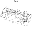
- Fig. 1 is a perspective view showing an ink jet recording apparatus, which is an embodiment of the invention.
- Fig. 2 is a block diagram showing an embodiment of the invention.
- Fig. 3 is a flowchart showing the overall operation of the apparatus.
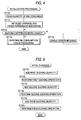
- Fig. 4 is a flowchart showing an operation for initialization processing out of the operation of the apparatus.
- Fig. 5 is a flowchart showing an operation for initial charging processing.
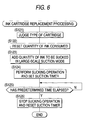
- Fig. 6 is a flowchart showing an operation for ink cartridge replacement processing.
- Fig. 7 is a flowchart showing an operation for cleaning processing.
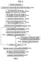
- Fig. 8 is a flowchart showing an operation for printing processing.
- Fig. 9 is a flowchart showing an operation for ink consumption check processing out of the operation of the apparatus.
- Fig. 10 is a flowchart showing large-scale suction processing, which is another embodiment of the invention.
- Fig. 11 is a flowchart showing small-scale suction processing, which is another embodiment of the invention.
- Fig. 1 shows an embodiment of the invention.
- a carriage 1 is connected to a motor 3 through a timing belt 2 and moves in parallel to a platen 5 while guided by a guide member 4.
- Recording heads 7, 8 are mounted on the carriage 1 surface that confronts a recording paper 6.
- the recording head 7 jets black ink onto a printing region (left side as viewed in Fig. 1) and the color printing recording head 8 is releasably mounted in a nonprinting region.
- the respective recording heads 7, 8 jet ink droplets onto the recording paper 6 while having inks supplied by a black ink cartridge 9 and a color ink cartridge 10, respectively.
- switches 11, 12 are disposed on the carriage 1. These switches 11, 12 are turned on and off upon loading and unloading the ink cartridges 9, 10.
- a capping device 13 is formed by mounting a cap member 14 for sealing the black ink recording head 7 and a cap member 15 for sealing the color ink recording head 8 on the same slider.
- the cap members 14, 15 are large enough to seal the nozzle opening surfaces of the recording heads 7, 8 in single spaces, respectively, and are connected through tubes to a pump unit 18.
- the capping device 13 thus is an example of means for sealing the ink jet recording head.
- the pump unit 18 includes two pumps 16, 17 that can be driven independently.
- the capping device 13 seals the nozzle openings during a nonprinting period, and forcibly discharges ink from the recording heads 7, 8 while being evacuated to a negative pressure by the pump unit 18 when the ink jetting capability recovering operation is being performed.
- a cleaner unit 19 is disposed in the vicinity of the capping device 13.
- the capping device 13 is an example of a structure that also doubles as a means for allowing the ink jet recording head to be evacuated to a negative pressure by the suction pump.
- the capping device performs the above-identified functions for sealing and for evacuation, it may, for convenience, be referred to simply as a capping means.
- Fig. 2 shows a controller for controlling the operation of the recording apparatus, the controller being an embodiment of the invention.
- a printing control means 20 generates bit map data based on printing data sent from a host, and jets ink droplets out of the recording heads 7, 8 by causing a head drive means 21 to produce drive signals based on the generated bit map data.
- An ink cartridge load/unload detecting means 22 detects the loading and unloading of the ink cartridges 9, 10 from signal changeovers of the respective switches 11, 12 disposed on the carriage 1.
- a load timer 23 resets itself upon loading the ink cartridges 9, 10 based on a signal from the ink cartridge load/unload detecting means 22 and thereafter starts measuring time, and then stops measuring time upon unloading the ink cartridges 9, 10.
- a pump driving means 24 performs a sucking operation based on the sucking strength, the sucking time, and the sucking interval defined by a suction control means 29 to be described later.
- a power supply sensing means 25 detects the supply of power to the apparatus, and outputs a signal upon turning on and off the power supply.
- a stop timer 26 starts measuring time upon turning off the power supply and stops measuring time upon turning on the power supply. That is, the stop timer 26 detects a time period during which the recording heads 7, 8 have continuously been sealed by the capping device 13.
- a flushing control means 27 jets a predetermined number of ink droplets out of all the nozzle openings of the respective recording heads 7, 8 after the carriage 1 has been evacuated to a flushing position, usually at the capping position, by the printing control means 20 upon detection by a print timer 28 of a predetermined time period for which a printing operation has lasted.
- the flushing operation is performed to prevent and eliminate nozzle clogging.
- the suction control means 29 operates the respective pumps 17, 18 in a predetermined mode by delivering a signal to the pump drive means 24 with the recording heads 7, 8 sealed by the capping device 13 based on a signal from a suction mode specifying means 31 to be described later.
- the suction control means 29 is designed to intervene when a signal is received from an externally operable cleaning switch 30, when new ink cartridges 9, 10 are loaded, or when the stop timer 26 has measured a predetermined time upon turning on the power supply.
- the suction mode specifying means 31 specifies a mode selected from one of three possible modes: large-scale suction mode, a small-scale suction mode, and a suction save mode in accordance with the remaining ink level of the ink cartridges 9, 10.
- An ink consumption operating means 32 reads the value corresponding to the quantity of ink consumed, which value is stored in a consumption storage means 33 to be described later.
- the ink consumption operating means 32 performs this reading operation when power supply sensing means 25 senses the turning on of the power supply.
- the ink consumption operating means counts the number of ink droplets whenever a printing operation or a flushing operation is performed. Based on the counted number of ink droplets, the ink consumption operating means calculates the quantity of ink consumed. This calculation of the quantity of ink consumed may be performed by multiplying the counted number of ink droplets by the quantity of ink per ink droplet. The quantity of ink used per ink droplet may be based on data stored in a coefficient setting means 37 to be described later.
- the ink consumption operating means may perform the calculation of the quantity of ink consumed by adding the quantity of ink to be sucked in advance.
- the coefficient setting means 37 stores data relating to the quantity of ink per ink droplet for color and black inks as- shown in Tables 1 and 2. That is, the coefficient setting means 37 stores data on the quantity by weight of ink per ink droplet for color and black inks so as to correspond to print modes such as a high-definition print mode, a normal print mode, and a draft print mode as shown in Table 1. Further, the coefficient setting means 37 stores data on the quantity by weight of ink per ink droplet for color and black inks so as to correspond not only to flushing operations (such as flushing before printing, periodic flushing during printing, and flushing after printing) but also to print modes for periodic flushing.
- flushing operations such as flushing before printing, periodic flushing during printing, and flushing after printing
- the quantity of ink per ink droplet be calculated so as to be temperature-compensated based on temperature data sent from a temperature detecting means 40.
- the ink droplet has a reference value of 1.
- the quantity of ink per ink droplet is actually about 1.03 times that of the reference value.
- the quantity of ink per ink droplet is actually about 1.05 times that of the reference value.
- the quantity of the ink discharged has a larger volume due to the reduced viscosity caused by increased temperature. Thereby, the amount of ink expended per ink droplet can reliably be added as a quantity of ink consumed. Therefore, this temperature compensation contributes greatly to determining correctly the ink consumption and thus is particularly contributory to preventing the running out of the ink during printing.
- the power supply sensing means 25 detects the turning off of the power supply, the calculated quantity of ink consumed is stored in the consumption storage means 33, and when a signal from a reset means 34 is applied upon detection of replacement of the ink cartridges 9, 10 by the ink cartridge load/unload detecting means 22, the calculated values are reset.
- a remaining ink level judging means 35 calculates a difference between the quantity of ink contained in the respective ink cartridges 9, 10 and the quantity of ink consumed calculated by the ink consumption operating means 32, and feeds a signal to the suction mode specifying means 31, and to a duty setting means 36 and a display means 38, which will be described later, every time the difference falls below one of a plurality of reference values that are defined by graduation.
- the ink end levels include a level in which the ink within the ink cartridges has run out and a level in which the ink at least remains in the ink cartridges after an ink sucking operation has been performed.
- the near end level is a level in which some 2 to 20 % of the total ink remains.
- the large-scale suction prohibit level is a level in which some 2 to 25% of the total ink remains.
- the suction prohibit level is a level in which some 2 to 30% of the total ink remains.
- the ink consumption operating means 32 of which a particularly high calculation capability is required, be incorporated as part of the function of the CPU belonging to the host apparatus through the printer driver software installed into the host apparatus.
- the power supply turn-off processing includes storing the quantity of ink calculated by the consumption operating means 32 into the consumption storage means 33.
- step S103 a determination is made as to whether or not the ink cartridges 9, 10 have been replaced. This determination is based on a signal from the ink cartridge load/unload detecting means 22. If the ink cartridges have been replaced, ink cartridge replacement processing (Fig. 6), which will be described later, is performed (S104).
- Processing then continues with a determination as to whether the cleaning button or switch 30 has been pressed. If the ink cartridge replacement processing has not been performed or if the cleaning switch 30 has been pressed after replacement of the ink cartridges 9, 10 has been complete (S105), then cleaning processing (Fig. 7), which will be described later, is performed (S106).
- Fig. 4 shows the details of initialization processing according to an embodiment of the invention (refer to S101 of Fig. 3).
- the consumption operating means 32 reads from the consumption storage means 33 the data relating to the quantity of ink already consumed (S110).
- the consumption storage means then performs initialization processing such as positioning carriage 1 and forwarding paper. These activities make the apparatus ready for printing (S111).
- the ink jet recording apparatus is designed to jet ink droplets out of nozzle openings by causing pressure producing chambers to apply pressure to the ink. Therefore, in view of such design, the ink jet recording apparatus is required to maintain the same condition both during shipment and during operation. That is, for meeting such requirement, measures to prevent the drying of the recording heads or entrance of dust into the recording heads are taken by charging a dummy solution into the recording heads. Therefore, prior to starting up the operation of the recording apparatus, the dummy solution charged into the recording heads 7, 8 must be completely discharged; i.e., a so-called initial loading operation must be performed.
- a first quantity of ink to be sucked which is the quantity of ink to be discharged by a first sucking operation
- a sucking operation is performed at the sucking speed specified for the first sucking operation (S116).
- a second quantity of ink to be sucked which is the quantity of ink to be discharged by a second sucking operation, is added to the consumption operating means 32 in advance (S117).
- a sucking operation is performed at the sucking speed specified for the second sucking operation (S118).
- a third quantity of ink to be sucked which is the quantity of ink to be discharged by a third sucking operation, is added to the consumption operating means 32 in advance (S119). Then, a sucking operation is performed at the sucking speed specified for the third sucking operation (S120).
- the quantities of ink to be used for initial charging are added, in advance, on a step-by-step basis before sucking operations are performed with respect to the ink cartridges 9, 10 in large quantities. Therefore, even if the power supply is turned off during a sucking operation, the quantity of ink remaining in the ink cartridges 9, 10 can conservatively be estimated. As a result, the running out of ink during printing and the draining of ink out of the recording heads 7, 8 can be avoided.
- the reset means 34 determines whether it is the black ink cartridge 9 or the color ink cartridge 10 that signals the detected ink level (S121). If it is the black ink cartridge 9 that signals the detected ink level, the quantity of ink consumed in the black ink cartridge is reset (S122), whereas if it is the color ink cartridge 10 that signals the detected ink level, the quantity of ink consumed in the color ink cartridge is similarly reset (S122).
- the quantity of ink consumed can be automatically reset only by performing the ink cartridge replacement processing. That is, the ink consumption resetting operation to be performed by the user after the ink cartridges have been replaced can be dispensed with, and the resetting errors so often associated with the user can be precluded.
- the ink consumption resetting operation is not performed by the ink consumption operating means 32 under the judgment that the user has erroneously unloaded and then loaded the same ink cartridges.
- the ink consumption operating means 32 even if it has been judged erroneously that the old ink cartridges have been unloaded and then loaded despite the fact that such old ink cartridges have actually been replaced with new ink cartridges, and even if the ink is thereafter sucked in large quantities for the cleaning processing and the like, the draining of ink from the recording heads 7, 8 can reliably be prevented.
- the remaining ink level judging means 35 judges that the ink remains in large quantities from the fact that the quantity of ink consumed has been reset.
- the suction mode specifying means 31 outputs to the suction control means 29 a signal indicating a large quantity of ink may be sucked in association with replacement of the ink cartridges.
- the suction control means 29 performs suction processing in the large-scale suction mode, which will be described later, and operates the suction timer 39 (S124).
- the suction timer 39 has measured a predetermined time T1 that is equivalent to the large quantity of ink to be sucked (S125)
- the suction processing is stopped and the suction timer 39 is then reset (S126).
- the remaining ink level (at the time the ink has been charged) indicated in relative terms (i.e., in percentage), but the remaining ink level also is controlled based on this percentage until a next replacement of the ink cartridges
- the quantity of ink that is given by subtracting the quantity of ink to be sucked in association with replacement of the ink cartridges as being 100% in this way, the user can be informed of the remaining ink level as correctly as possible.
- the quantity of ink given by subtracting the quantity of ink to be sucked that is equivalent to the quantity of ink to be initially charged is displayed as being 100%.
- the user can be informed of the remaining ink levels more simply, and the indication that the remaining ink level is 100% gives the user a sign that the ink charging operation has been terminated. Hence, the user can recognize the end of the ink charging operation without any special display.
- the volume of data printed by such a printing operation is judged (S129). If the volume of data printed is large, then, the large-scale suction prohibit mode (S130) is released. Then, the quantity of ink to be sucked in the small-scale suction mode is added to the consumption operating means 32 (S131). Next, a small-scale sucking operation is performed (S132).
- the cleaning counter indicates a predetermined number, e.g., 3, the cleaning counter is reset to 1. If the cleaning counter indicates a number lower than 3, then, after incrementing the number (S134), the quantity of ink to be consumed by large-scale suction is added to the consumption operating means 32 in advance (S135), and a sucking operation is performed in the large-scale suction mode (S136).
- the quantity of ink to be sucked is added to the consumption operating means 32 in advance. That is, such addition processing precedes the suction processing. Therefore, unlike the case where the quantity of ink to be sucked is added after a sucking operation, even if the power supply or the like is interrupted during the suction processing, the remaining ink level of the ink cartridges 9, 10 can be set to a value on the safety side; i.e., the remaining ink level can conservatively be estimated. Hence, this processing is advantageous in preventing the draining of ink from and the introduction of bubbles into the recording heads 7, 8 due to the ink having been consumed by the suction processing.
- the quantity of ink to be consumed by the flushing processing before printing which is to be performed prior to a printing operation is added to the ink consumption operating means 32 in advance (S141), and the flushing processing before printing is thereafter performed (S142).
- the average quantity of ink to be consumed per pass of printing e.g., the quantity of ink equivalent to half the maximum printing volume is added in advance (S143).
- the printing operation is started (S144), the total number of dots per pass is counted (S145), and the quantity of ink actually consumed by a single pass of printing is calculated by multiplying the counted total number of dots by the quantity of ink per droplet, and the calculated value is then added (S146).
- printing speed is reduced, e.g., by switching to a mode in which a single line of data is printed with a plurality of passes.
- the ink absorbing body is prevented from being evacuated to a negative pressure due to the ink therein having been consumed.
- the ink present in the regions of the ink cartridges 9, 10 that are remote from the ink discharge ports connected to the recording heads 7, 8 can be allowed to flow into the recording heads 7, 8 reliably, whereby the ink that is running low can more effectively be used up.
- the ink remaining in small quantities in the cartridges 9, 10 can reliably be supplied to the recording heads 7, 8 by reducing the printing speed or by switching to the mode in which a single line of data is printed with a plurality of passes when the data having an extremely heavy print duty such as graphic printing data are to be taken care of.
- a printing operation is performed after adding the average quantity of ink to be consumed by a single pass of printing prior to initiating the printing operation, and then the quantity of ink added in advance as an estimate is subtracted upon end of the single pass of printing. Therefore, by doing so, the quantity of ink actually consumed that cannot be added unless the single pass of printing is terminated can be added in the form of an equivalent quantity even if such addition cannot be made due to the power supply having been turned off. As a result, the remaining ink level in the ink cartridges can be estimated to a value as close to the actual value as possible, so that a possible running out of the ink during printing can be precluded.
- the remaining ink level of the loaded ink cartridges 9, 10 is calculated by taking into account the product of the elapsed time from the timing at which the cartridges 9, 10 for which the load timer 23 is operating have been loaded and the evaporation rate per unit time of an ink solvent from the cartridges 9, 10, the ink tubes, and the like (S154).
- step S155 the remaining ink level is compared with ink end judgment reference levels (S156). If the remaining ink level is judged to be at the ink end level, a message to that effect is displayed on the display means 38 (S157), and there is provided a prompt to replace the ink cartridges 9, 10. If the remaining ink level is judged to be between the ink end level and the near end level (S158), then a message "near end level" is displayed on the display means 38 (S159).
- the large-scale suction prohibit mode is specified (S161) so as to prevent the ink from inadvertently being consumed in large quantities by cleaning.
- the cleaning switch 30 If the cleaning switch 30 has already been pressed prior to the ink consumption check processing (S155), it is judged before cleaning whether the remaining ink level is at the ink end level by comparing the remaining ink level with the ink end judgment level so that the apparatus gets ready for consuming ink for cleaning (S165). If it is judged that the remaining ink level is below the ink end level according to such judgment level, then the remaining ink level is judged to be at the ink end level even if a printing operation can be performed at such remaining ink level, and a message "ink end level" is displayed on the display means 38 (S157), and replacement of the ink cartridges 9, 10 is prompted before cleaning.
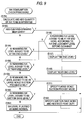
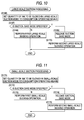
- the suction mode may be altered in accordance with the remaining ink levels. That is, as shown in Fig. 10 and Fig. 11, the quantities of ink to be sucked by suction-processing are set to the consumption operating means 32 in advance (Fig. 10 (S166), Fig. 11 (S171)), and then it is judged whether or not the suction save mode is specified (Fig. 10 (S167), Fig. 11 (S172)). If the suction save mode is not specified, a first large-scale sucking operation (Fig. 10 (S168)) or a first small-scale sucking operation (Fig. 11 (S173)) is performed through a normal sucking operation, the first sucking operations sucking the specified quantity of ink.
- a first large-scale sucking operation Fig. 10 (S168)
- a first small-scale sucking operation Fig. 11 (S173)
- the suction save mode is specified while the remaining ink level is judged to be at the suction save level by the ink consumption check processing (Fig. 9) due to the ink in the ink cartridges 9, 10 having been reduced (Fig. 10 (S167), Fig. 11 (S172)), the suction save mode is released (Fig. 10 (S169), Fig. 11 (S174)), and a second large-scale sucking operation (Fig. 10 (S170)) or a second small-scale sucking operation (Fig. 11 (S175)) for sucking the added quantity of ink may be performed by suppressing the flow of ink during sucking while reducing the numbers of revolutions of the pumps 16, 17, driving the pumps 17, 18 intermittently, or the like.
- the flow of ink to be sucked is suppressed without changing the quantity of ink needed for large-scale suction or small-scale suction.
- an ink cartridge is of such type that an ink absorbing body made of a porous elastic body or the like is impregnated with ink
- the quantity of ink needed for cleaning processing can be discharged while preventing interruption of the smooth flow of ink within the ink absorbing body. If the ink is running low, the quantity of ink needed for printing can be fed to the recording heads 7, 8 without interrupting smooth flow of ink within the ink absorbing body by reducing the printing speed. Therefore, the cartridges 9, 10 whose ink is running low can be consumed without being wasted.
Abstract
Description
- integrating quantities of ink consumed, using a counter, based on the sum of the product of the number of dots during printing and the quantity of ink to be consumed per ink droplet and the product of the quantity of ink to be sucked per forced sucking operation for preventing the clogging of nozzle openings and the number of sucking operations;
- displaying the remaining ink level by storing the integrated quantity of ink consumed; and
- allowing the integrated quantity of ink consumed to be reset through an external operation. That is, the approach to control of the remaining ink level evidenced in the four examples mentioned above is to use software. As the example steps just shown reveal, the general software-based approach takes advantage of the functions of a microcomputer incorporated in the recording apparatus.
| QUANTITY BY WEIGHT OF INK PER INK DROPLET FOR PRINTING | ||||
| MODE | WEIGHT (ng) | |||
| | BLACK | 1 | | |
| HIGH- | 25 | 60 | 20 | |
| NORMAL PRINT MODE | 50 | 130 | 50 | |
| DRAFT PRINT MODE | 60 | 120 | 55 |
| QUANTITY BY WEIGHT OF INK PER INK DROPLET FOR FLUSHING | ||||
| MODE | WEIGHT (ng) | |||
| | BLACK | 1 | | |
| PRE-PRINTING FLUSHING | 55 | 140 | 54 | |
| PERIODIC FLUSHING | HIGH- | 25 | 60 | 20 |
| NORMAL PRINT MODE | 50 | 130 | 50 | |
| DRAFT PRINT MODE | 60 | 120 | 55 | |
| PRE-ENDING FLUSHING | 60 | 150 | 58 |
| JUDGMENT LEVEL | |
| JUDGMENT LEVEL | REMAINING INK LEVEL (%) |
| INK END | 0 |
| INK END BEFORE | 1 ∼ 5 |
| NEAR | 2 ∼ 20 |
| LARGE-SCALE SUCTION PROHIBIT | 2 ∼ 25 |
| SUCTION PROHIBIT | 2 ∼ 30 |
Claims (28)
- An ink jet recording apparatus comprising:an ink jet recording head (7) for jetting an ink droplet in accordance with printing data;an ink cartridge (9, 10) supplying ink to said recording head (7);capping means (13) comprising means (14, 15) for sealing said recording head (7);a suction pump (18) for evacuating said capping means (13) to a negative pressure;suction control means (29) comprising means for controlling suction processing for discharging said ink by sucking said recording head (7) with said suction pump (18); andremaining ink level judging means (35) comprising means for conrolling a quantity of ink in said ink cartridge (9, 10) by integrating quantities of ink discharged from said recording head (7);
wherein said remaining ink level judging means (35) adds a quantity of ink to be discharged by said suction processing as a quantity of ink consumed, said addition being made before said suction processing is performed. - An ink jet recording apparatus according to claim 1, wherein:said suction processing is intermittently performed a plurality of times; anda quantity of ink is to be discharged by said sucking operation in said plurality of times is added as a quantity of ink consumed before starting to perform said sucking operation said plurality of times.
- An ink jet recording apparatus according to claim 1, further comprising:flushing means (27) comprising means (20, 28) for jetting an ink droplet to prevent said recording head from clogging; anda quantity of ink to be discharged by flushing processing being added as a quantity of ink consumed before said flushing processing is performed.
- An ink jet recording apparatus according to claim 3, further comprising means for setting a quantity of ink to be jetted per ink droplet during said flushing processing.
- An ink jet recording apparatus according to claim 1, further comprising means for reducing a printing speed when a remaining ink level judged by said remaining ink level judging means (35) is equal to or smaller than a predetermined value.
- An ink jet recording apparatus comprising:an ink jet recording head (7) for jetting an ink droplet in accordance with printing data;an ink cartridge (9, 10) supplying ink to said recording head (7);capping means (13) comprising means (14, 15) for sealing said recording head;a suction pump (18) for evacuating said capping means (13) to a negative pressure;suction control means (29) comprising means for controlling suction processing for discharging said ink by sucking said recording head (7) with said suction pump (18); andremaining ink level judging means (35) comprising means for judging a remaining ink level of said ink cartridge;
wherein, when said remaining ink level is equal to or smaller than a predetermined value, said suction control means (29) limits a quantity of ink to be sucked. - An ink jet recording apparatus according to claim 6, further comprising:flushing means (27) comprising means for jetting an ink droplet to prevent said recording head from clogging; anda quantity of ink to be discharged by flushing processing being added as a quantity of ink consumed before said flushing processing is performed.
- An ink jet recording apparatus according to claim 7, further comprising means (20) for setting a quantity of ink to be jetted per ink droplet during said flushing processing.
- An ink jet recording apparatus according to claim 6, further comprising means (20) for setting a print duty based on said remaining ink level judged by said remaining ink level judging means (35).
- An ink jet recording apparatus according to claim 6, further comprising means (20) for reducing a printing speed when a remaining ink level judged by said remaining ink level judging means (35) is equal to or smaller than a predetermined value.
- An ink jet recording apparatus comprising:an ink jet recording head (7) for jetting an ink droplet in accordance with printing data;an ink cartridge (9, 10) supplying ink to said recording head (7);capping means (13) comprising means (14, 15) for sealing said recording head (7);a suction pump (18) for evacuating said capping means (13) to a negative pressure:suction control means (29) comprising means for controlling suction processing for discharging said ink by sucking said recording head (7) with said suction pump (18) ;andremaining ink level judging means (35) comprising means for judging a remaining ink level of said ink cartridge (9, 10);
wherein, when said remaining ink level is equal to or smaller than a predetermined value, said suction control means (29) limits an ink sucking speed. - An ink jet recording apparatus according to claim 11, further comprising means (20) for setting a print duty based on said remaining ink level judged by said remaining ink level judging means (35).
- An ink jet recording apparatus comprising:an ink jet recording head (7) for jetting an ink droplet in accordance with printing data;an ink cartridge (9, 10) supplying ink to said recording head (7); andremaining ink level judging means (35) comprising means for adding a quantity of ink to be jetted out of said recording head (7), based on said printing data, every predetermined printing operation of said recording head (7).
- An ink jet recording apparatus according to claim 13, wherein said remaining ink level judging means (35) adjusts a quantity of ink to be jetted per ink droplet during printing so as to correspond to a printing mode.
- An ink jet recording apparatus according to claim 13, wherein:ink consumption judging means (32, 33) adds a quantity of ink to be consumed per pass in advance of starting a printing operation; andsaid ink consumption judging means (35) subtracts said added quantity of ink after having terminated said printing operation.
- An ink jet recording apparatus according to claim 13, further comprising:flushing means (27) comprising means for jetting an ink droplet to prevent said recording head (7) from clogging; anda quantity of ink to be discharged by flushing processing being added as a quantity of ink consumed before said flushing processing is performed.
- An ink jet recording apparatus according to claim 16, further comprising means (20) for setting a quantity of ink to be jetted per ink droplet during said flushing processing.
- An ink jet recording apparatus according to claim 13, further comprising means (20) for setting a print duty based on said remaining ink level judged by said remaining ink level judging means.
- An ink jet recording apparatus according to claim 13, wherein said quantity of ink to be jetted per ink droplet is changed in accordance with the ink temperature.
- An ink jet recording apparatus according to claim 13, further comprising means (20) for reducing a printing speed when a remaining ink level judged by said remaining ink level judging means is equal to or smaller than a predetermined value.
- An ink jet recording apparatus comprising:an ink jet recording head (7) for jetting an ink droplet in accordance with printing data;an ink cartridge (9, 10) supplying ink to said recording head;capping means (13) comprising means (14, 15) for sealing said recording head;a suction pump (18) for evacuating said capping means to a negative pressure;suction control means (29) comprising means for controlling suction processing for discharging said ink by sucking said recording head (7) with said suction pump (18);remaining ink level judging means (35) comprising means for controlling a quantity of ink in said ink cartridge (9, 10) by integrating quantities of ink discharged from said recording head (7); andmeans for relatively displaying said remaining ink level as being full, after performing said suction processing, when a new ink cartridge has been loaded to said recording head (7);
wherein said remaining ink level judging means (35) adds a quantity of ink to be discharged by said suction processing, as a quantity of ink consumed, before said sucking operation is performed. - An ink jet recording apparatus according to claim 21, wherein said remaining ink level is displayed on a host computer.
- An ink jet recording apparatus comprising:an ink jet recording head (7) for jetting an ink droplet in accordance with printing data;an ink cartridge (9, 10) supplying ink to said recording head;remaining ink level judging means (35) comprising means for adding a quantity of ink to be jetted Out of said recording head, based on said printing data, every time said recording head performs a predetermined printing operation; andload time detecting means (23) comprising means for detecting an integrated time for which said ink cartridge (9, 10) has been loaded to said recording head (7);
wherein said remaining ink level judging means (35) judges and displays said remaining ink level taking into account a quantity of ink evaporated from said ink cartridge (9, 10) based on said integrated time. - An ink jet recording apparatus according to claim 23, wherein said remaining ink level is displayed on a host computer.
- An ink jet recording apparatus comprising:an ink jet recording head (7) for jetting an ink droplet in accordance with printing data; an ink cartridge (9, 10) supplying ink to said recording head (7);capping means (13) comprising means (14, 15) for sealing said recording head (7);a suction pump (18) for evacuating said capping means (13) to a negative pressure;suction control means (29) comprising means for controlling suction processing for discharging said ink by sucking said recording head (7) with said suction pump (18); andremaining ink level judging means (35) comprising means for controlling a quantity of ink in said ink cartridge by integrating quantites of ink discharged from said recording head (7);
wherein said remaining ink level judging means (35) has at least two judgement levels, including an ink end judgement level used during printing and an ink end judgement level used before performing said sucking operation. - An ink jet recording apparatus according to claim 25, wherein said remaining ink level judging means (35) further includes a third judgement level substantially the same as said ink judgement level immediately before performing said suction processing, said third judgement level defining an ink near end judgement level used during printing.
- An ink jet recording apparatus comprising:an ink jet recording head (7) for jetting an ink droplet in accordance with printing data;an ink cartridge (9, 10) supplying ink to said recording head (7);remaining ink level judgement means (35) comprising means for adding a quantity of ink to be jetted out of said recording head (7) based on printing data every time said recording head (7) performs a predetermined printing operation; andink cartridge replacement detecting means (11, 12, 22) comprising means for detecting replacement of said ink cartridge (9, 10);
wherein, when said remaining ink level is lower than a second ink end level that is slightly higher than an ink end judgement level, said remaining ink level judging means (35) is reset by a signal from said ink cartridge replacement detecting means (11, 12, 22). - An ink jet recording apparatus comprising:an ink jet recording head (7) for jetting an ink droplet in accordance with printing data;an ink cartridge (9, 10) supplying ink to said recording head (7);capping means (13) comprising means (14, 15) for sealing said recording head;a suction pump (18) for evacuating said capping means (13) to a negative pressure;suction control means (29) comprising means for controlling suction processing for discharging said ink by sucking said recording head (7) with said suction pump (18);remaining ink level judging means (35) comprising means for managing a quantity of ink in said ink cartridge (9, 10) by integrating quantities of ink discharged from said recording head (7) and adding a quantity of ink to be jetted out of said recording head (7) based on said printing data every time said recording head (7) performs a predetermined printing operation; andink cartridge replacement detecting means (11, 12, 22) comprising means for detecting replacement of said ink cartridge (9, 10);
wherein said remaining ink level judging means (35) has at least three judgement levels, including a first ink end judgement level used during printing; a second ink end judgement level used before performing said sucking operation; and a third ink end judgement level slightly higher than said first ink end judgement level, and
wherein, when said remaining ink level is below said third ink end judgement level, said remaining ink level judgement means (35) is reset by a signal from said ink cartridge replacement detecting means (11, 12, 22).
Priority Applications (3)
| Application Number | Priority Date | Filing Date | Title |
|---|---|---|---|
| EP00113492A EP1050412B1 (en) | 1996-11-11 | 1997-11-11 | Ink jet recording apparatus |
| EP00113491A EP1052100B1 (en) | 1996-11-11 | 1997-11-11 | Ink jet recording apparatus |
| EP03003762A EP1314566A1 (en) | 1996-11-11 | 1997-11-11 | Ink-jet recording apparatus |
Applications Claiming Priority (12)
| Application Number | Priority Date | Filing Date | Title |
|---|---|---|---|
| JP31420996 | 1996-11-11 | ||
| JP31420996 | 1996-11-11 | ||
| JP314209/96 | 1996-11-11 | ||
| JP21598897A JPH10181044A (en) | 1996-11-11 | 1997-07-25 | Ink jet recorder |
| JP21598897 | 1997-07-25 | ||
| JP215989/97 | 1997-07-25 | ||
| JP21598997 | 1997-07-25 | ||
| JP21598997A JPH10181045A (en) | 1996-11-11 | 1997-07-25 | Ink jet recorder |
| JP215988/97 | 1997-07-25 | ||
| JP9220198A JPH10181046A (en) | 1996-11-11 | 1997-07-31 | Ink jet recorder |
| JP22019897 | 1997-07-31 | ||
| JP220198/97 | 1997-07-31 |
Related Child Applications (2)
| Application Number | Title | Priority Date | Filing Date |
|---|---|---|---|
| EP00113492A Division EP1050412B1 (en) | 1996-11-11 | 1997-11-11 | Ink jet recording apparatus |
| EP00113491A Division EP1052100B1 (en) | 1996-11-11 | 1997-11-11 | Ink jet recording apparatus |
Publications (3)
| Publication Number | Publication Date |
|---|---|
| EP0841173A2 true EP0841173A2 (en) | 1998-05-13 |
| EP0841173A3 EP0841173A3 (en) | 1998-12-16 |
| EP0841173B1 EP0841173B1 (en) | 2002-09-18 |
Family
ID=27476756
Family Applications (4)
| Application Number | Title | Priority Date | Filing Date |
|---|---|---|---|
| EP00113491A Expired - Lifetime EP1052100B1 (en) | 1996-11-11 | 1997-11-11 | Ink jet recording apparatus |
| EP00113492A Expired - Lifetime EP1050412B1 (en) | 1996-11-11 | 1997-11-11 | Ink jet recording apparatus |
| EP97119731A Expired - Lifetime EP0841173B1 (en) | 1996-11-11 | 1997-11-11 | Ink jet recording apparatus |
| EP03003762A Withdrawn EP1314566A1 (en) | 1996-11-11 | 1997-11-11 | Ink-jet recording apparatus |
Family Applications Before (2)
| Application Number | Title | Priority Date | Filing Date |
|---|---|---|---|
| EP00113491A Expired - Lifetime EP1052100B1 (en) | 1996-11-11 | 1997-11-11 | Ink jet recording apparatus |
| EP00113492A Expired - Lifetime EP1050412B1 (en) | 1996-11-11 | 1997-11-11 | Ink jet recording apparatus |
Family Applications After (1)
| Application Number | Title | Priority Date | Filing Date |
|---|---|---|---|
| EP03003762A Withdrawn EP1314566A1 (en) | 1996-11-11 | 1997-11-11 | Ink-jet recording apparatus |
Country Status (3)
| Country | Link |
|---|---|
| US (1) | US6174042B1 (en) |
| EP (4) | EP1052100B1 (en) |
| DE (3) | DE69723481T2 (en) |
Cited By (10)
| Publication number | Priority date | Publication date | Assignee | Title |
|---|---|---|---|---|
| EP1142713A2 (en) * | 1999-11-05 | 2001-10-10 | Seiko Epson Corporation | Inkjet type recording device and method of supplying ink to sub-tank by the same device, and method of checking amount of ink supplied to sub-tank by the same device |
| EP1184181A1 (en) * | 2000-08-24 | 2002-03-06 | Hewlett Packard Company, a Delaware Corporation | Method and system for determining usage of a print solution for a print operation |
| US6428132B1 (en) * | 1999-11-26 | 2002-08-06 | Francotyp-Postalia Ag & Co. | Method for determining the number of normal imprints implementable with a remaining ink quantity and arrangement for the implementation of the method |
| EP1249349A1 (en) * | 2001-04-13 | 2002-10-16 | Seiko Epson Corporation | Ink jet recording apparatus and ink end judging method executed in the same |
| US6491367B1 (en) * | 1999-02-08 | 2002-12-10 | Seiko Epson Corporation | Printer, a printer cleaning method, and a cleaning method storage medium |
| EP1270226A2 (en) * | 2001-06-14 | 2003-01-02 | Seiko Epson Corporation | Ink consumption amount-calculating method and device, ink jet printer incorporating the device, printing cost-calculating system, and coloring material supply management system |
| US6866355B2 (en) * | 2000-12-21 | 2005-03-15 | Seiko Epson Corporation | Ink jet recording apparatus, and method of supplying ink to sub-tank of the ink jet recording apparatus |
| US6969136B1 (en) * | 1998-05-25 | 2005-11-29 | Seiko Epson Corporation | Ink cartridge, ink-jet printing apparatus, and refilling device |
| EP1974920A3 (en) * | 2007-03-30 | 2008-11-05 | Brother Kogyo Kabushiki Kaisha | Droplet ejection device |
| WO2020117417A1 (en) * | 2018-12-04 | 2020-06-11 | Hewlett-Packard Development Company, L.P. | Ink cartridge activation |
Families Citing this family (19)
| Publication number | Priority date | Publication date | Assignee | Title |
|---|---|---|---|---|
| JP3854770B2 (en) * | 2000-02-24 | 2006-12-06 | キヤノン株式会社 | Inkjet printing device |
| US6357854B1 (en) * | 2000-04-26 | 2002-03-19 | Pitney Bowes Inc. | Ink jet printer having waste tank overflow prevention |
| JP2002273906A (en) * | 2001-01-09 | 2002-09-25 | Seiko Epson Corp | Ink jet recording device and correction method for ink consumption arithmetic function for the device |
| ATE402017T1 (en) | 2001-02-09 | 2008-08-15 | Seiko Epson Corp | INKJET RECORDING APPARATUS, CONTROL AND INK REFILLING METHODS PERFORMED IN THE APPARATUS, INK SUPPLY SYSTEM IN THE APPARATUS, AND METHODS OF MANAGEMENT OF THE QUANTITY OF INK SUPPORTED BY THE SYSTEM |
| JP2003127353A (en) * | 2001-08-10 | 2003-05-08 | Canon Inc | Ink jet recording device |
| US6786566B2 (en) * | 2001-12-17 | 2004-09-07 | Brother Kogyo Kabushiki Kaisha | Ink jet recording apparatus |
| DE10332225B4 (en) * | 2003-07-16 | 2005-07-07 | Tally Computerdrucker Gmbh | A method and apparatus for determining and monitoring the instantaneous amount of ink liquid in an ink reservoir of an ink printer |
| JP4725084B2 (en) * | 2004-11-19 | 2011-07-13 | セイコーエプソン株式会社 | Liquid ejector |
| JP4577783B2 (en) | 2006-04-25 | 2010-11-10 | 株式会社沖データ | Image forming apparatus |
| GB0608762D0 (en) * | 2006-05-04 | 2006-06-14 | Domino Printing Sciences Plc | Improvements in or relating to continuous inkjet printers |
| JP4721068B2 (en) * | 2007-12-28 | 2011-07-13 | ブラザー工業株式会社 | Inkjet recording device |
| JP5725798B2 (en) * | 2010-11-01 | 2015-05-27 | キヤノン株式会社 | Control device, control device state detection method, and program |
| US9004636B2 (en) * | 2012-04-20 | 2015-04-14 | Hewlett-Packard Development Company, L.P. | Fluid drops provided in print mode and maintenance mode in normal consumption state and low consumption state |
| JP6395510B2 (en) * | 2014-08-25 | 2018-09-26 | キヤノン株式会社 | Ink jet recording apparatus and control method thereof |
| JP6557978B2 (en) | 2015-01-21 | 2019-08-14 | ブラザー工業株式会社 | Inkjet recording apparatus and program |
| JP6390444B2 (en) | 2015-01-21 | 2018-09-19 | ブラザー工業株式会社 | Inkjet recording apparatus and program |
| JP6428294B2 (en) | 2015-01-21 | 2018-11-28 | ブラザー工業株式会社 | Inkjet recording apparatus and program |
| JP2017136787A (en) * | 2016-02-05 | 2017-08-10 | セイコーエプソン株式会社 | Droplet discharge device and calculation method for liquid used amount in the same |
| JP6874728B2 (en) * | 2018-03-30 | 2021-05-19 | ブラザー工業株式会社 | Liquid drainer |
Citations (7)
| Publication number | Priority date | Publication date | Assignee | Title |
|---|---|---|---|---|
| EP0398348A2 (en) * | 1989-05-18 | 1990-11-22 | Canon Kabushiki Kaisha | An ink jet recording apparatus |
| WO1992018335A1 (en) * | 1991-04-17 | 1992-10-29 | Eastman Kodak Company | Ink residual quantity sensor of ink jet printer |
| EP0552472A2 (en) * | 1991-12-24 | 1993-07-28 | Seiko Epson Corporation | Ink-expelling restoring device and method for ink jet printer |
| EP0615846A1 (en) * | 1993-03-11 | 1994-09-21 | Seiko Epson Corporation | Ink jet recording apparatus |
| JPH07276667A (en) * | 1994-04-08 | 1995-10-24 | Brother Ind Ltd | Image formation device |
| JPH07309018A (en) * | 1994-05-19 | 1995-11-28 | Brother Ind Ltd | Ink jet recording apparatus |
| EP0707969A2 (en) * | 1994-10-20 | 1996-04-24 | Canon Kabushiki Kaisha | Information processing apparatus and method for use in system with remote printer |
Family Cites Families (10)
| Publication number | Priority date | Publication date | Assignee | Title |
|---|---|---|---|---|
| US6000778A (en) * | 1989-05-18 | 1999-12-14 | Canon Kabushiki Kaisha | Recording apparatus recovery method using variable pressure |
| JP3120476B2 (en) | 1991-02-26 | 2000-12-25 | 東レ株式会社 | Color paste for color filters |
| JPH0588552A (en) | 1991-09-27 | 1993-04-09 | Yokogawa Hewlett Packard Ltd | Method for detecting remaining ink on printer |
| JPH07205419A (en) | 1994-01-26 | 1995-08-08 | Canon Inc | Ink jet device |
| US5663750A (en) * | 1994-04-05 | 1997-09-02 | Brother Kogyo Kabushiki Kaisha | Ink ejection device with ink saving mode used when remaining ink amount is small |
| JP3267449B2 (en) * | 1994-05-31 | 2002-03-18 | セイコーエプソン株式会社 | Ink jet recording device |
| JPH07323552A (en) * | 1994-05-31 | 1995-12-12 | Canon Inc | Ink droplet discharge quantity controlling method, ink jet recorder and information processing system |
| JPH082649A (en) | 1994-06-22 | 1996-01-09 | Toyo Glass Kikai Kk | Safety system for conveyor driving part of shaping machine |
| US5844583A (en) * | 1994-07-14 | 1998-12-01 | Seiko Epson Corporation | Ink jet recording method and apparatus providing a plurality of image resolutions with the same amount of ink per dot |
| JP3601102B2 (en) * | 1995-03-15 | 2004-12-15 | ブラザー工業株式会社 | Ink-jet printing recorder and printing system |
-
1997
- 1997-11-11 EP EP00113491A patent/EP1052100B1/en not_active Expired - Lifetime
- 1997-11-11 EP EP00113492A patent/EP1050412B1/en not_active Expired - Lifetime
- 1997-11-11 EP EP97119731A patent/EP0841173B1/en not_active Expired - Lifetime
- 1997-11-11 DE DE69723481T patent/DE69723481T2/en not_active Expired - Lifetime
- 1997-11-11 EP EP03003762A patent/EP1314566A1/en not_active Withdrawn
- 1997-11-11 DE DE69723482T patent/DE69723482T2/en not_active Expired - Lifetime
- 1997-11-11 DE DE69715561T patent/DE69715561T2/en not_active Expired - Lifetime
- 1997-11-12 US US08/967,819 patent/US6174042B1/en not_active Expired - Lifetime
Patent Citations (7)
| Publication number | Priority date | Publication date | Assignee | Title |
|---|---|---|---|---|
| EP0398348A2 (en) * | 1989-05-18 | 1990-11-22 | Canon Kabushiki Kaisha | An ink jet recording apparatus |
| WO1992018335A1 (en) * | 1991-04-17 | 1992-10-29 | Eastman Kodak Company | Ink residual quantity sensor of ink jet printer |
| EP0552472A2 (en) * | 1991-12-24 | 1993-07-28 | Seiko Epson Corporation | Ink-expelling restoring device and method for ink jet printer |
| EP0615846A1 (en) * | 1993-03-11 | 1994-09-21 | Seiko Epson Corporation | Ink jet recording apparatus |
| JPH07276667A (en) * | 1994-04-08 | 1995-10-24 | Brother Ind Ltd | Image formation device |
| JPH07309018A (en) * | 1994-05-19 | 1995-11-28 | Brother Ind Ltd | Ink jet recording apparatus |
| EP0707969A2 (en) * | 1994-10-20 | 1996-04-24 | Canon Kabushiki Kaisha | Information processing apparatus and method for use in system with remote printer |
Non-Patent Citations (2)
| Title |
|---|
| PATENT ABSTRACTS OF JAPAN vol. 096, no. 002, 29 February 1996 & JP 07 276667 A (BROTHER IND LTD), 24 October 1995 * |
| PATENT ABSTRACTS OF JAPAN vol. 096, no. 003, 29 March 1996 & JP 07 309018 A (BROTHER IND LTD), 28 November 1995 * |
Cited By (16)
| Publication number | Priority date | Publication date | Assignee | Title |
|---|---|---|---|---|
| US6969136B1 (en) * | 1998-05-25 | 2005-11-29 | Seiko Epson Corporation | Ink cartridge, ink-jet printing apparatus, and refilling device |
| US7014305B2 (en) | 1998-05-25 | 2006-03-21 | Seiko Epson Corporation | Ink cartridge |
| US6491367B1 (en) * | 1999-02-08 | 2002-12-10 | Seiko Epson Corporation | Printer, a printer cleaning method, and a cleaning method storage medium |
| US6796627B2 (en) * | 1999-11-05 | 2004-09-28 | Seiko Epson Corporation | Ink jet recording apparatus, method of replenishing ink to subtank in the apparatus, and method of checking the replenished amount of ink |
| EP1142713A2 (en) * | 1999-11-05 | 2001-10-10 | Seiko Epson Corporation | Inkjet type recording device and method of supplying ink to sub-tank by the same device, and method of checking amount of ink supplied to sub-tank by the same device |
| EP1142713A4 (en) * | 1999-11-05 | 2005-04-20 | Seiko Epson Corp | Inkjet type recording device and method of supplying ink to sub-tank by the same device, and method of checking amount of ink supplied to sub-tank by the same device |
| US6428132B1 (en) * | 1999-11-26 | 2002-08-06 | Francotyp-Postalia Ag & Co. | Method for determining the number of normal imprints implementable with a remaining ink quantity and arrangement for the implementation of the method |
| EP1184181A1 (en) * | 2000-08-24 | 2002-03-06 | Hewlett Packard Company, a Delaware Corporation | Method and system for determining usage of a print solution for a print operation |
| US6866355B2 (en) * | 2000-12-21 | 2005-03-15 | Seiko Epson Corporation | Ink jet recording apparatus, and method of supplying ink to sub-tank of the ink jet recording apparatus |
| US6913336B2 (en) | 2001-04-13 | 2005-07-05 | Seiko Epson Corporation | Ink jet recording apparatus and ink end judging method executed in the same |
| EP1249349A1 (en) * | 2001-04-13 | 2002-10-16 | Seiko Epson Corporation | Ink jet recording apparatus and ink end judging method executed in the same |
| EP1270226A3 (en) * | 2001-06-14 | 2003-02-26 | Seiko Epson Corporation | Ink consumption amount-calculating method and device, ink jet printer incorporating the device, printing cost-calculating system, and coloring material supply management system |
| EP1270226A2 (en) * | 2001-06-14 | 2003-01-02 | Seiko Epson Corporation | Ink consumption amount-calculating method and device, ink jet printer incorporating the device, printing cost-calculating system, and coloring material supply management system |
| EP1974920A3 (en) * | 2007-03-30 | 2008-11-05 | Brother Kogyo Kabushiki Kaisha | Droplet ejection device |
| WO2020117417A1 (en) * | 2018-12-04 | 2020-06-11 | Hewlett-Packard Development Company, L.P. | Ink cartridge activation |
| US11485146B2 (en) | 2018-12-04 | 2022-11-01 | Hewlett-Packard Development Company, L.P. | Ink cartridge activation |
Also Published As
| Publication number | Publication date |
|---|---|
| EP1314566A1 (en) | 2003-05-28 |
| DE69715561T2 (en) | 2003-05-22 |
| EP0841173A3 (en) | 1998-12-16 |
| DE69723481D1 (en) | 2003-08-14 |
| DE69723482T2 (en) | 2003-12-24 |
| EP1052100B1 (en) | 2003-07-09 |
| DE69723481T2 (en) | 2003-12-24 |
| EP1050412A3 (en) | 2001-08-29 |
| DE69723482D1 (en) | 2003-08-14 |
| EP1052100A3 (en) | 2001-08-29 |
| US6174042B1 (en) | 2001-01-16 |
| EP1050412B1 (en) | 2003-07-09 |
| EP0841173B1 (en) | 2002-09-18 |
| EP1050412A2 (en) | 2000-11-08 |
| DE69715561D1 (en) | 2002-10-24 |
| EP1052100A2 (en) | 2000-11-15 |
Similar Documents
| Publication | Publication Date | Title |
|---|---|---|
| EP0841173B1 (en) | Ink jet recording apparatus | |
| EP0844094B1 (en) | Ink-jet recording device | |
| EP0640483A2 (en) | Method and device for detecting the ink level in a cartridge | |
| US11117380B2 (en) | Liquid ejection apparatus and method of controlling liquid ejection apparatus | |
| US5997120A (en) | Recording apparatus which allows ink amount detection upon exchange of a printhead | |
| EP1386744B1 (en) | Ink-jet recording device | |
| US7625077B2 (en) | Liquid cartridge, liquid ejection apparatus and liquid ejection control method | |
| JP3543781B2 (en) | Ink jet recording device | |
| US6976746B2 (en) | Ink jet recording apparatus adapted to display state of use or time for replacement of cartridge and control method for same | |
| JP2003039696A (en) | Method for detecting residual quantity of ink and ink jet recorder | |
| US6312088B1 (en) | Ink jet recording apparatus | |
| EP1025997B1 (en) | Inkjet printing apparatus, method of cleaning its ink jet head and storage medium | |
| JP3829900B2 (en) | Inkjet printer and ink cartridge replacement detection method | |
| JP2003231273A (en) | Inkjet recorder | |
| JPH10181044A (en) | Ink jet recorder | |
| JPH10181046A (en) | Ink jet recorder | |
| JPH11192732A (en) | Ink jet recording apparatus | |
| JPH10181045A (en) | Ink jet recorder | |
| JPH08238780A (en) | Record control method and ink jet record device | |
| JP2003094686A (en) | Inkjet printer and maintenance method therefor | |
| JPH0834123A (en) | Ink jet recording device | |
| JP2004160938A (en) | Liquid jet device and liquid vessel used therefor | |
| JP2001260375A (en) | Apparatus and method for detecting remaining quantity of ink and ink jet recording apparatus | |
| JP2004122424A (en) | Ink jet recorder | |
| JP2003039709A (en) | Ink jet recorder and method for controlling maintenance of recording head thereof |
Legal Events
| Date | Code | Title | Description |
|---|---|---|---|
| PUAI | Public reference made under article 153(3) epc to a published international application that has entered the european phase |
Free format text: ORIGINAL CODE: 0009012 |
|
| AK | Designated contracting states |
Kind code of ref document: A2 Designated state(s): DE FR GB IT |
|
| AX | Request for extension of the european patent |
Free format text: AL;LT;LV;MK;RO;SI |
|
| PUAL | Search report despatched |
Free format text: ORIGINAL CODE: 0009013 |
|
| AK | Designated contracting states |
Kind code of ref document: A3 Designated state(s): AT BE CH DE DK ES FI FR GB GR IE IT LI LU MC NL PT SE |
|
| AX | Request for extension of the european patent |
Free format text: AL;LT;LV;MK;RO;SI |
|
| 17P | Request for examination filed |
Effective date: 19990215 |
|
| AKX | Designation fees paid |
Free format text: DE FR GB IT |
|
| 17Q | First examination report despatched |
Effective date: 20000126 |
|
| GRAG | Despatch of communication of intention to grant |
Free format text: ORIGINAL CODE: EPIDOS AGRA |
|
| GRAG | Despatch of communication of intention to grant |
Free format text: ORIGINAL CODE: EPIDOS AGRA |
|
| GRAH | Despatch of communication of intention to grant a patent |
Free format text: ORIGINAL CODE: EPIDOS IGRA |
|
| GRAH | Despatch of communication of intention to grant a patent |
Free format text: ORIGINAL CODE: EPIDOS IGRA |
|
| GRAA | (expected) grant |
Free format text: ORIGINAL CODE: 0009210 |
|
| AK | Designated contracting states |
Kind code of ref document: B1 Designated state(s): DE FR GB IT |
|
| REG | Reference to a national code |
Ref country code: GB Ref legal event code: FG4D |
|
| REF | Corresponds to: |
Ref document number: 69715561 Country of ref document: DE Date of ref document: 20021024 |
|
| ET | Fr: translation filed | ||
| PLBE | No opposition filed within time limit |
Free format text: ORIGINAL CODE: 0009261 |
|
| STAA | Information on the status of an ep patent application or granted ep patent |
Free format text: STATUS: NO OPPOSITION FILED WITHIN TIME LIMIT |
|
| 26N | No opposition filed |
Effective date: 20030619 |
|
| REG | Reference to a national code |
Ref country code: FR Ref legal event code: PLFP Year of fee payment: 19 |
|
| REG | Reference to a national code |
Ref country code: FR Ref legal event code: PLFP Year of fee payment: 20 |
|
| PGFP | Annual fee paid to national office [announced via postgrant information from national office to epo] |
Ref country code: GB Payment date: 20161109 Year of fee payment: 20 Ref country code: DE Payment date: 20161108 Year of fee payment: 20 Ref country code: FR Payment date: 20161014 Year of fee payment: 20 |
|
| PGFP | Annual fee paid to national office [announced via postgrant information from national office to epo] |
Ref country code: IT Payment date: 20161122 Year of fee payment: 20 |
|
| REG | Reference to a national code |
Ref country code: DE Ref legal event code: R071 Ref document number: 69715561 Country of ref document: DE |
|
| REG | Reference to a national code |
Ref country code: GB Ref legal event code: PE20 Expiry date: 20171110 |
|
| PG25 | Lapsed in a contracting state [announced via postgrant information from national office to epo] |
Ref country code: GB Free format text: LAPSE BECAUSE OF EXPIRATION OF PROTECTION Effective date: 20171110 |