EP0840869B1 - Pipeline vehicle - Google Patents
Pipeline vehicle Download PDFInfo
- Publication number
- EP0840869B1 EP0840869B1 EP96914327A EP96914327A EP0840869B1 EP 0840869 B1 EP0840869 B1 EP 0840869B1 EP 96914327 A EP96914327 A EP 96914327A EP 96914327 A EP96914327 A EP 96914327A EP 0840869 B1 EP0840869 B1 EP 0840869B1
- Authority
- EP
- European Patent Office
- Prior art keywords
- vehicle
- module
- pipe
- pipeline
- probe
- Prior art date
- Legal status (The legal status is an assumption and is not a legal conclusion. Google has not performed a legal analysis and makes no representation as to the accuracy of the status listed.)
- Expired - Lifetime
Links
Images


Classifications
-
- G—PHYSICS
- G01—MEASURING; TESTING
- G01V—GEOPHYSICS; GRAVITATIONAL MEASUREMENTS; DETECTING MASSES OR OBJECTS; TAGS
- G01V3/00—Electric or magnetic prospecting or detecting; Measuring magnetic field characteristics of the earth, e.g. declination, deviation
- G01V3/18—Electric or magnetic prospecting or detecting; Measuring magnetic field characteristics of the earth, e.g. declination, deviation specially adapted for well-logging
- G01V3/26—Electric or magnetic prospecting or detecting; Measuring magnetic field characteristics of the earth, e.g. declination, deviation specially adapted for well-logging operating with magnetic or electric fields produced or modified either by the surrounding earth formation or by the detecting device
-
- F—MECHANICAL ENGINEERING; LIGHTING; HEATING; WEAPONS; BLASTING
- F16—ENGINEERING ELEMENTS AND UNITS; GENERAL MEASURES FOR PRODUCING AND MAINTAINING EFFECTIVE FUNCTIONING OF MACHINES OR INSTALLATIONS; THERMAL INSULATION IN GENERAL
- F16L—PIPES; JOINTS OR FITTINGS FOR PIPES; SUPPORTS FOR PIPES, CABLES OR PROTECTIVE TUBING; MEANS FOR THERMAL INSULATION IN GENERAL
- F16L55/00—Devices or appurtenances for use in, or in connection with, pipes or pipe systems
- F16L55/26—Pigs or moles, i.e. devices movable in a pipe or conduit with or without self-contained propulsion means
- F16L55/28—Constructional aspects
-
- G—PHYSICS
- G01—MEASURING; TESTING
- G01N—INVESTIGATING OR ANALYSING MATERIALS BY DETERMINING THEIR CHEMICAL OR PHYSICAL PROPERTIES
- G01N27/00—Investigating or analysing materials by the use of electric, electrochemical, or magnetic means
- G01N27/72—Investigating or analysing materials by the use of electric, electrochemical, or magnetic means by investigating magnetic variables
- G01N27/82—Investigating or analysing materials by the use of electric, electrochemical, or magnetic means by investigating magnetic variables for investigating the presence of flaws
- G01N27/90—Investigating or analysing materials by the use of electric, electrochemical, or magnetic means by investigating magnetic variables for investigating the presence of flaws using eddy currents
- G01N27/9013—Arrangements for scanning
- G01N27/902—Arrangements for scanning by moving the sensors
-
- G—PHYSICS
- G01—MEASURING; TESTING
- G01V—GEOPHYSICS; GRAVITATIONAL MEASUREMENTS; DETECTING MASSES OR OBJECTS; TAGS
- G01V3/00—Electric or magnetic prospecting or detecting; Measuring magnetic field characteristics of the earth, e.g. declination, deviation
- G01V3/15—Electric or magnetic prospecting or detecting; Measuring magnetic field characteristics of the earth, e.g. declination, deviation specially adapted for use during transport, e.g. by a person, vehicle or boat
-
- F—MECHANICAL ENGINEERING; LIGHTING; HEATING; WEAPONS; BLASTING
- F16—ENGINEERING ELEMENTS AND UNITS; GENERAL MEASURES FOR PRODUCING AND MAINTAINING EFFECTIVE FUNCTIONING OF MACHINES OR INSTALLATIONS; THERMAL INSULATION IN GENERAL
- F16L—PIPES; JOINTS OR FITTINGS FOR PIPES; SUPPORTS FOR PIPES, CABLES OR PROTECTIVE TUBING; MEANS FOR THERMAL INSULATION IN GENERAL
- F16L2101/00—Uses or applications of pigs or moles
- F16L2101/30—Inspecting, measuring or testing
Definitions
- the invention relates to an in-pipe vehicle which can carry out an operation within a pipeline, which pipeline may be a gas carrying pipeline.
- a pipeline device includes an arrangement for forming an aperture in a liner, the device being pulled by a wire or pushed by a rod.
- a remotely controlled device has a magnetic sensor and an arangement for marking a pipe junction to allow an opening to be formed later.
- the present invention is concerned generally with an arrangement which will allow operations to be undertaken from within the pipeline, without the need for external drives, umbilicals or other connections which restrict the movement or utility of such arrangements.
- a pipeline vehicle comprising a plurality of linked modules forming a powered train for travelling within a pipeline, at least one of the modules being capable of carrying out an operation on the pipeline and wherein a module includes clamping means for holding the vehicle at a fixed point in the pipeline whilst rotational means are operable to axially rotate part or parts of the vehicle relative to the pipeline bore to align the module capable of carrying out the operation.
- a method of effecting an operation on a pipeline comprising passing a vehicle consisting of a train of separate flexibly linked modules through the pipeline to detect the presence of an item to be operated on, moving the vehicle to align a module with the item to carry out the desired operation, the alignment step including clamping the vehicle and during the clamping step effecting axial rotational movement of the module relative to the pipeline bore.
- an elongate flexible probe for insertion into and passage along an auxiliary pipe from an end remote from a main pipe and for indicating the proximity of the auxiliary pipe to a device within a main pipe, said probe including means for generating a magnetic field for detection by the device within the main pipe, indication means associated with the probe for generating a signal when the probe is adjacent the main pipe, and means to enable the probe to travel along a pipe.
- a buried cast iron gas main pipeline 1 shown in Figure 1 carries a polyethylene pipe liner 2 which has previously been inserted through excavation 3 as part of a refurbishment programme.
- a number of existing service pipe take-offs 4 each provide the source of gas to individual dwellings or other premises.
- As part of the refurbishment programme there is a need to insert a liner in each service pipe and to join this to the main liner 2.
- In order to achieve this it has been necessary in the past to make an excavation at each service connection 5 (e.g. a screwed pipe connector or a service tee) and penetrate the main liner 2 through the excavation, sealing the take off to the main using a saddle connection, having removed part of the cast iron main in that region.
- each service connection 5 e.g. a screwed pipe connector or a service tee
- the self-powered in-pipe vehicle 10 of Figure 2 includes a plurality of dissimilar individual modules 11 - 16 linked via similar linkage and suspension modules 17.
- the train of modular elements allows flexibility of operation in that each module provides a specific function which in this embodiment work together to remotely connect polyethylene gas main to service piping inserted into old metal piping (as described below). Other modular configurations would allow further tasks to be effected.
- the modular arrangement together with the suspension modules allows the degree of serpentine operation needed to negotiate bends in the pipe and to cope with the small diameter of the pipe which can be less than 150mm.
- the first module in the train is the traction module 11 which includes a motor 20 within one of the arms 22, 23 terminating in drive wheels 26 and idler wheels 25 respectively.
- the moveable arms 22 and 23 allow the wheels to contact closely the inner wall of the pipe through which it traverses and sensors within both the idler and drive wheel detect slippage which causes the traction unit to cause the arm to extend further to increase the traction affect. This can be effected by a motor driven ball screw acting on the lever arm to control the transverse load.
- the motor 20 drives the wheels via gearing and feedback on movement, direction and slippage which can be compensated by internal control.
- the traction unit provides a pushing force for the train of 80 N at a speed of 30 mm/s.
- Power for the modules including the traction module 11 is provided by the power unit 12 which incorporates a number of rechargeable batteries.
- Electrical connection to the modules is provided via the suspension unit 17 connectors.
- the suspension units 17 are provided of common construction and placed between each functional module to give the train flexibility required for small pipes.
- Each module 17 includes three spring loaded arms 30 terminating in wheels 31. In order to avoid the use of highly preloaded suspension springs, the three lever arms at one end are interconnected via a slider.
- a central shaft 33 through each suspension unit is free to rotate relative to the body. Connectors at each end allow electrical connection between all modules to be effected for power and intercommunication requirements.
- the manipulator module 13 includes three retractable extenders 40 which are controlled to extend when required beyond the manipulator's cylindrical body 41 so as to firmly support the module as it becomes wedged in the pipe.
- a motor with associated gearing (e.g. ring gear) and feedback allows the rear portion of manipulator to rotate relative to the front portion and as the modules are all mechanically linked this causes modules connected to the rear of the manipulator to axially rotate within the pipe so that they can be aligned to a certain portion of the pipe to effect a task when required.
- a 'global' rotational manipulation for all modules has been found effective rather than each module making adjustments themselves, although 'local' manipulation may be required in addition for a given module.
- the rotational manipulation can provide two 210° arcs with the body clamped against the pipe wall. Electrical connection through the rotating interface within the manipulator is provided by use of a coiled cable to avoid slip ring interference and reduce module length.
- the sensor module 14 includes a number of magnetic sensors 50 spaced around the periphery of the module for detecting a magnetic field from a source which is typically within the module 14.
- the sensors (typically 40 in number) form part of a variable reluctance magnetic circuit.
- the detectors can be of the Hall effect type.
- the hole in the offtake corresponds to the largest loss and indicates its position.
- the drill module 15 includes a motorised drill bit 60 capable of drilling a hole through the pipe, but more typically through the pipe liner.
- a 16mm hole would be suitable to access a 25mm service pipe tee.
- the fusion module 16 carries a sensor 70 (e.g. a force sensor with variable resistance when contacted by a guide wire) for detecting the guide wire in the service pipe liner (for reasons described below) and a heater device 71 for effecting a seal between the main liner and the service pipe liner.
- the manipulator module 13 allows the rotation by 180° of the train including module 16 to allow the sensing and sealing functions to be effected.
- a master controller circuit can be located within the power module 12 and individual modules have localised control circuits to effect tasks associated with their particular devices.
- the master controller and the module controllers can be formed from a common approach using a hierarchial modular organisation of control and monitor process operating on independent communicating modules.
- the master controller is aware of operations being effected by individual modules and ensures the required tasks are carried out.
- Each module control arrangement includes a control board sensor and actuators of common hardware design with operation mode selection under software control. Such a module control system is shown in Figure 3.
- Analogue module sensors 80 connect to a programmable peripheral interface 81 which carries an onboard analog to digital converter (ADC) and digital I/O lines.
- Digital sensors 89 connect to the digital inputs.
- Information from the interface is made available to microprocessor 82 which includes associated data storage RAM 83 and program storage ROM 84.
- a communication link 85 is also available to communicate with other modules.
- the microprocessor accesses sensor information via interface 81 (e.g. type HD631408) and controls the loads 90, (e.g. motors or other operational devices such as heaters) via decoder 86 and driver circuits 87. Current monitoring feedback is provided via line 88.
- Power supply regulation block 92 ensures trouble-free power supply requirements.
- the microprocessor can be a T225 transputer contains a RISC CPU (16bit 25MHZ) and interprocessor communications links.
- Power for the devices can be high capacity nickel cadmium rechargeable batteries of the 'pancake' configuration.
- the system can be sufficiently intelligent to carry out the tasks without external control although with a radio link (e.g. 1.394GHZ) it is possible to send information on operations being effected to an 'above ground' station using the pipeline as a waveguide. Return signals could be sent to override or halt tasks if they are detected as being inappropriate.
- a radio link e.g. 1.394GHZ
- the train of modules is driven by module 11 along the pipe until detector module 14 detects a service tee through the main liner.
- the aperture will typically be at the highest point in the pipe wall but the actual position is determined by the detectors.
- the train will then move on until the drill module 15 is at the correct position beneath the tee.
- the manipulator module 13 then activates its extenders 40 to clamp the module. If the drill is not determined to be in front of the aperture from earlier calculations, the module then rotates in an arc to line up the drill.
- the manipulator module 13 retracts its extenders and the train moves forwards until the fusion module 16 is determined to be located beneath the service tee.
- the manipulator module 13 again activates its extenders and clamps itself to the main pipe. A rotation of the module is effected if it is determined that this is necessary to locate the detector 70 in front of the tee.
- the hole already drilled in the main liner allows the service pipe liner to be inserted through the service pipe using a very flexible guide wire.
- the service liner has at its front end a tapered lead component formed from cross-linked polyethylene. The presence of the guide wire confirms to the detector that the correct service tee is being refurbished. Once the lead end is located in the drilled hole, the guide wire is removed, indicating that the jointing step can be effected.
- the manipulator 13 rotates through 180° to locate the heater device 71 on the fusion module 16 adjacent to the region of the service liner end, within the main liner hole and electric power is applied to the heater to fuse the joint in the liners by raising the temperature to the crystalline melt stage, causing the service liner end-piece to expand and fuse simultaneously to the main liner.
- the manipulator module contracts its extenders 40 and the train of modules moved on along the pipe until it detects the presence of the next service pipe, when the operations can proceed once again.
- the magnetic source for sensor module 14 may be a coil producing a field which is radial with respect to the wall of the main which is detected as falling in the region of the offtake, it is possible to use a permanent magnet arrangement as an alternative within the module.
- FIG. 4 shows such an arrangement using bar magnets 100.
- a bar magnet 100 associated with each sensor 102 (a Hall effect device having a linear output).
- Each sensor 102 is protected by potting compound 103.
- Each sensor 102 is mounted on a sledge 104 which is reciprocable radially and urged outwardly by two compression springs 106, 108.
- Each sledge 104 is guided by a pin 110 fixed to the sledge 104 and reciprocable in a bore 112 in a central fixed body 114.
- the body 114 is part of a module 116 equivalent to module 14 of Figure 2 which forms the train which is movable through main 10.
- the upper half of Figure 4 shows a sledge 104 in its innermost position as dictated by the minimum radius which the liner 12 presents.
- the lower half of Figure 4 shows a sledge 104 in its outermost position as dictated by the maximum radius which the line 12 presents.
- Figure 4 is presented merely for information regarding the inward and outward movement of the sledges 104.
- the module 116 occupies a central position in the main. As a result, all the sledges 104 occupy similar radial positions with respect to the body 114.
- Each sledge 104 is retained by pins 120, 122 fixed in the body 114 and projecting into slideways 124, 126 in the sledge 104.
- Each slideway 124, 126 terminates in an axially extending clearance hole 128, 130.
- Each sledge 104 can be removed from the body 114 by holding it in its radially innermost position, as shown in the upper half of Figure 2 and knocking the pins 120, 122 inwardly into the clearance holes 128, 130.
- Each sensor 102 has a multi-conductor lead 140 by which the sensor 102 is connected to the detector to electronics (not shown) housed in the housing 142 secured to one end of the body 114.
- the magnetic lines of force generated by the bar magnet 100 leave the magnet 100 at its right-hand end and are turned radially outwardly by a block 150 of ferromagnetic material.
- the lines of force pass through the liner 12 and enter the cast iron main 10.
- the lines of force travel leftward through the main 10, then turn radially inward and pass through the liner 12, through the sensor 102 and enter another block of ferromagnetic material 152.
- the direction of the lines of magnetic lines of force change from radially inward to horizontal in the block 152 and then the lines of force enter the left hand end of the magnet 100.
- a block 154 of plastics material bridges the gap between the two blocks 150, 152 of ferromagnetic material.
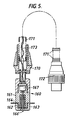
- Figure 5 shows an elongate probe 160 including a head portion 161.
- the head portion includes a magnetic source coil 162 having a ferrite core and located within brass housing 163.
- a plastic guide washer 164 e.g. tri-cornered PTFE
- switch activator 166 is provided coupled to switch 167.
- the head is connected to steel housing 170 to which is coupled a flexible coil-like spring tube 171 which terminates in plug 172.
- the hollow tube 171 carries the connecting wires 173 for the switch and coil.
- the tube 171 is typically about 4 metres long and is sufficiently flexible to pass through bends and other potential obstacles in the pipe.
- the plug 172 connects with the transmission electronics within housing 180 via socket 181.
- the electronic circuit includes a waveform generator IC, 187 (e.g. ICL 8038) connected to a battery power source 182 via switch 183.
- Lamps 184 and 185 e.g. LEDs indicate circuit operation and when the probe contacts the main liner.
- the generator produces an output frequency of about 35 KHz at 14 volts peak to peak.
- the light 185 is illuminated and the probe is in the correct position for the in pipe vehicle to detect the ac magnetic field. Once the vehicle has detected the source, it can send a signal to the surface to allow the probe to be partially withdrawn while the drilling operation is being effected.
- the detector module 14 of the in pipe vehicle is modified to detect the source within the service pipe and can include an arrangement of the form shown in Figure 7. It could alternatively be mounted within the drill module.
- the coil assembly includes a large diameter wound coil 190 which is the course position detector coil.
- a second fine position coil 191 assembly includes two separate windings at 90° angles to give an 'x' and 'y' co-ordinate coil 192 and 193 and associated capacitors 194, 195 and resistor 196.
- the signal field information detected by the coils 190, 191 is received by the processing circuit of Figure 8.
- This circuit includes amplifiers 200 and 201 and RMS to DC converters 202, 203 and filters 204, 205.
- the dc outputs are converted into digital form via A to D converter 206 before handling by the vehicle computer system 207 (of the type shown in Figure 3).
- the robot In operation, the robot is driven down the supply pipe towards the magnetic field radiated by the source located in the service tee.
- the induced voltage in the coarse coil increases and reaches a maximum as the flux cuts it at right angles. It falls to a minimum as it passes through the centre of the source and the axis of the field is in line with the coil.
- the service tee is adjacent to the coil but it can be at any location around the circumference of the pipe.
- This coarse position is logged by the robot vehicle Transputer (microprocessor) and used to reposition the drill module bringing the fine coil to the same position.
- the Transputer When the fine coils are in the pipe section identified by the coarse coil, the Transputer initiates a search pattern, to locate the centre of the source coil. This tracks the drill module in rotational and longitudinal directions until the output from the coils is at a minimum or null.
- the drill module When the fine coils are positioned at the centre of the source coil the drill module is rotated by 90 degrees which brings the drill bit in line with the centre of the source coil. The process is completed by energising the drill to cut a hole in the PE liner to take the new PE service pipe as described earlier.
- the probe in the service pipe can be removed and replaced with the guide wire which carries the service pipe liner, before fusing this liner to the main pipe liner.
Description
Each sensor 102 is mounted on a
Claims (34)
- A pipeline vehicle (10) comprising a plurality of linked modules (11-16) forming a powered train for travelling within a pipeline, at least one of the modules (15) being capable of carrying out an operation on the pipeline and wherein a module includes clamping means (40) for holding the vehicle at a fixed point in the pipeline whilst rotational means are operable to axially rotate part or parts of the vehicle relative to the pipeline bore to align the module (15) capable of carrying out the operation.
- A vehicle as claimed in claim 1 wherein a traction module (11) provides the driving power for the vehicle and including drive means for varying the degree of friction between the traction module and the pipe.
- A vehicle as claimed in claim 1 or 2 wherein one module (14) includes detector means for detecting a pipe junction within the main pipeline.
- A vehicle as claimed in claim 3 wherein the detector means includes a plurality of magnetic sensors (50; 102) for detecting the relative circumferential position of the junction within the pipe.
- A vehicle as claimed in claim 3 or 4 wherein a magnetic source (100) is carried within the detector module.
- A vehicle as claimed in claim 3 or 4 wherein the magnetic source includes a coil (162) for generating a magnetic field.
- A vehicle as claimed in claim 3 or 4 wherein a magnetic source is provided externally of the module using alternating current to generate a magnetic field.
- A vehicle as claimed in any preceding claim wherein a module includes drill means (60) provided to cause an aperture to be made through or into the pipe or a lining therein.
- A vehicle as claimed in any preceding claim wherein a module includes means (71) for heating a plastic pipe to cause a joint to be effected between a main pipe and a smaller diameter pipe extending therefrom.
- A vehicle as claimed in any preceding claim wherein one module (13) comprises an elongate cylindrical body having a first cylindrical portion configured to grip the pipeline and a second cylindrical portion coaxial therewith and configured to rotate whilst the first portion grips the pipeline.
- A vehicle as claimed in claim 10 wherein the diameter of the cylindrical body is no more than 150 mm.
- A vehicle as claimed in any preceding claim including a computer device (82) within a module for receiving an output from a plurality of sensors (80, 89) via interface means (81), said computer means being configured to automatically determine firstly when a pipe junction has been reached, secondly to determine the orientation of the junction, thirdly the amount of axial rotation and forward movement required to align the module capable of carrying out the operation on the pipeline.
- A vehicle as claimed in claim 12 including transmitter means for communicating between the vehicle and the surface, said transmitter means being configured to use the pipeline as a waveguide.
- A vehicle as claimed in any preceding claim including a plurality of dissimilar modules (13-16) each for carrying out a different function on the pipeline.
- A vehicle as claimed in claim 14 including a module (14) for detecting a branch, another module (13) for clamping the vehicle and a further module (15) for cutting through a liner within the pipeline.
- A vehicle as claimed in claimed in any preceding claim wherein flexible links (30-33) are provided to assist in manoeuvring the vehicle.
- A vehicle as claimed in claim 16 wherein the links are carried on a plurality of wheeled intermediate modules (17).
- A method of effecting an operation on a pipeline comprising passing a vehicle consisting of a train of separate flexibly linked modules through the pipeline to detect the presence of an item to be operated on, moving the vehicle to align a module with the item to carry out the desired operation, the alignment step including clamping the vehicle and during the clamping step effecting axial rotational movement of the module relative to the pipeline bore.
- A method as claimed in claim 18 wherein the module for carrying out the operation is moved longitudinally and axially to assist in alignment.
- A method as claimed in claim 18 or 19 wherein a drilling module is aligned in the pipe to effect drilling of a main pipe liner.
- A method as claimed in claim 20 wherein a sealing module is aligned in the pipe to seal an auxiliary pipe liner to the main liner.
- A self powered and self controlled pipeline vehicle as claimed in claim 1 or 2 having a generally cylindrical body portion configured to move generally coaxially within the pipeline bore and including detector means (50, 102) for detecting the presence of a pipe junction in a main pipeline, means (60) for forming an aperture in a liner within the main pipeline, and wherein the rotational means axially rotates a body portion relative to the pipeline bore to align the aperture forming means with the pipe junction prior to forming the aperture at the pipe junction, without remote control requirements.
- A vehicle as claimed in claim 22 wherein the detector means is a magnetic detector (50, 102) for detecting a magnetic field in the region of the junction.
- A vehicle as claimed in claim 23 wherein the detector means includes a course detector coil (190) and a fine detector coil (191) for assisting in location detection.
- A vehicle as claimed in claim 23 wherein the detector includes a magnetic source (100).
- A vehicle as claimed in any one of claims 22 to 25 wherein the vehicle comprises a plurality of articulated modules linked by intermediate suspension modules (17).
- A vehicle as claimed in any one of claims 22 to 26 including sealing means (16) for sealing an auxiliary pipe liner to the main liner.
- A vehicle as claimed in any one of claims 22 to 27 comprising a plurality of linked modules (11-16) for serpentine movement through the pipeline.
- A vehicle as claimed in any one of claims 22 to 28 wherein self control means (80-90) includes a computer device (82) connected to the detector means (50) for determining when the pipe junction has been reached and for determining the orientation of the junction to control the means (13) for axially rotating the body to align the aperture forming means.
- A vehicle as claimed in any one of claims 22 to 29 including friction control means (22-26) for varying the degree of friction between the fraction module and the pipe.
- An elongate flexible probe (160) for insertion into and passage along an auxiliary pipe from an end remote from a main pipe and for indicating the proximity of the auxiliary pipe to a device within the main pipe, said probe including means (162) for generating a magnetic field for detection by the device within the main pipe, indication means (185) associated with the probe for generating a signal when the probe is adjacent the main pipe and means (171, 173) to enable the probe to travel along a pipe.
- A probe as claimed in claim 31 including a flexible coil-like spring tube (171) for assisting the passage of the probe through the auxiliary pipe.
- A probe as claimed in claim 31 or 32 wherein the means for generating a field includes a coil (162) with an electronic circuit (187) for generating an alternating current signal.
- A probe as claimed in claim 31, 32 or 33 wherein the means for generating a signal includes a switch (167) operable when the probe contacts the main pipe or liner.
Applications Claiming Priority (3)
| Application Number | Priority Date | Filing Date | Title |
|---|---|---|---|
| GB9510434 | 1995-05-22 | ||
| GB9510434A GB2301187B (en) | 1995-05-22 | 1995-05-22 | Method of and apparatus for locating an anomaly in a duct |
| PCT/GB1996/001214 WO1996037727A1 (en) | 1995-05-22 | 1996-05-21 | Pipeline vehicle |
Publications (2)
| Publication Number | Publication Date |
|---|---|
| EP0840869A1 EP0840869A1 (en) | 1998-05-13 |
| EP0840869B1 true EP0840869B1 (en) | 2002-03-06 |
Family
ID=10774908
Family Applications (1)
| Application Number | Title | Priority Date | Filing Date |
|---|---|---|---|
| EP96914327A Expired - Lifetime EP0840869B1 (en) | 1995-05-22 | 1996-05-21 | Pipeline vehicle |
Country Status (9)
| Country | Link |
|---|---|
| US (4) | US5878783A (en) |
| EP (1) | EP0840869B1 (en) |
| JP (2) | JP3561276B2 (en) |
| CA (2) | CA2173193A1 (en) |
| DE (1) | DE69619678T2 (en) |
| ES (1) | ES2174070T3 (en) |
| GB (2) | GB2301187B (en) |
| HK (2) | HK1010904A1 (en) |
| WO (1) | WO1996037727A1 (en) |
Cited By (2)
| Publication number | Priority date | Publication date | Assignee | Title |
|---|---|---|---|---|
| WO2012102611A1 (en) | 2011-01-25 | 2012-08-02 | Jelcer-Ip B.V. | A pipe travelling apparatus and use thereof |
| CN109612366A (en) * | 2018-11-21 | 2019-04-12 | 山东里能鲁西矿业有限公司 | A kind of novel recyclable roof separation indicator |
Families Citing this family (155)
| Publication number | Priority date | Publication date | Assignee | Title |
|---|---|---|---|---|
| US6857486B2 (en) * | 2001-08-19 | 2005-02-22 | Smart Drilling And Completion, Inc. | High power umbilicals for subterranean electric drilling machines and remotely operated vehicles |
| GB2301187B (en) * | 1995-05-22 | 1999-04-21 | British Gas Plc | Method of and apparatus for locating an anomaly in a duct |
| BR9610373A (en) * | 1995-08-22 | 1999-12-21 | Western Well Toll Inc | Traction-thrust hole tool |
| GB9614761D0 (en) * | 1996-07-13 | 1996-09-04 | Schlumberger Ltd | Downhole tool and method |
| EP0991892A1 (en) | 1997-06-26 | 2000-04-12 | Gas Research Institute | System for inspecting in-service gas distribution mains |
| CA2218436A1 (en) * | 1997-10-15 | 1999-04-15 | Consolidated Edison Company Of New York, Inc. | Device for repairing pipes |
| US6240965B1 (en) * | 1998-04-24 | 2001-06-05 | Link-Pipe (H.K.), Ltd. | Apparatus for repair of high temperature and pressure conduits, method for repairing high temperature and pressure conduits, and a sealing device for repairing high temperature and pressure conduits |
| AR018459A1 (en) * | 1998-06-12 | 2001-11-14 | Shell Int Research | METHOD AND PROVISION FOR MOVING EQUIPMENT TO AND THROUGH A VAIVEN CONDUCT AND DEVICE TO BE USED IN SUCH PROVISION |
| GB2351308B (en) | 1998-12-18 | 2003-05-28 | Western Well Tool Inc | Electro-hydraulically controlled tractor |
| US6347674B1 (en) * | 1998-12-18 | 2002-02-19 | Western Well Tool, Inc. | Electrically sequenced tractor |
| FR2790087B1 (en) * | 1999-02-19 | 2001-04-20 | Coflexip | METHOD AND DEVICE FOR IN SITU MEASURING THE DISTANCE BETWEEN TWO GIVEN ELEMENTS IN A TUBULAR PIPE |
| NO320782B1 (en) * | 1999-03-22 | 2006-01-30 | Aatechnology As | Progress mechanism for long voids and rudders |
| US6820653B1 (en) * | 1999-04-12 | 2004-11-23 | Carnegie Mellon University | Pipe inspection and repair system |
| US9586699B1 (en) | 1999-08-16 | 2017-03-07 | Smart Drilling And Completion, Inc. | Methods and apparatus for monitoring and fixing holes in composite aircraft |
| NO311100B1 (en) * | 1999-10-26 | 2001-10-08 | Bakke Technology As | Apparatus for use in feeding a rotary downhole tool and using the apparatus |
| US6626447B2 (en) * | 2000-01-28 | 2003-09-30 | Barnard Construction Co., Inc. | Pipeline patch trolley |
| US6464003B2 (en) | 2000-05-18 | 2002-10-15 | Western Well Tool, Inc. | Gripper assembly for downhole tractors |
| US6450104B1 (en) * | 2000-04-28 | 2002-09-17 | North Carolina State University | Modular observation crawler and sensing instrument and method for operating same |
| FR2808491B1 (en) * | 2000-05-04 | 2002-08-09 | Cie Du Sol | A SELF-PROPELLED TROLLEY CAPABLE OF MOVING IN A CYLINDRICAL GALLERY |
| FR2812067B1 (en) * | 2000-07-18 | 2003-05-16 | Commissariat Energie Atomique | MOBILE ROBOT ABLE TO WORK IN PIPES OR OTHER NARROW PASSAGES |
| US7121364B2 (en) * | 2003-02-10 | 2006-10-17 | Western Well Tool, Inc. | Tractor with improved valve system |
| US8245796B2 (en) * | 2000-12-01 | 2012-08-21 | Wwt International, Inc. | Tractor with improved valve system |
| WO2002044509A2 (en) | 2000-12-01 | 2002-06-06 | Western Well Tool, Inc. | Tractor with improved valve system |
| CA2354226A1 (en) | 2001-01-31 | 2002-07-31 | Cal Holland | Robotic apparatus and method for non-destructive maintenance of intersecting conduits |
| US20020113870A1 (en) * | 2001-02-16 | 2002-08-22 | Mueckl Gareth J. | Pipeline televising apparatus with wireless remote controller |
| EP1373783B1 (en) * | 2001-03-07 | 2005-08-03 | Carnegie-Mellon University | Gas main robotic inspection system |
| WO2002093408A1 (en) * | 2001-05-11 | 2002-11-21 | Wildseed, Ltd. | Method and system for collecting and displaying aggregate presence information for mobile media players |
| US6431291B1 (en) | 2001-06-14 | 2002-08-13 | Western Well Tool, Inc. | Packerfoot with bladder assembly having reduced likelihood of bladder delamination |
| US6427602B1 (en) | 2001-07-02 | 2002-08-06 | Westinghouse Savannah River Company, Llc | Pipe crawler apparatus |
| US8515677B1 (en) | 2002-08-15 | 2013-08-20 | Smart Drilling And Completion, Inc. | Methods and apparatus to prevent failures of fiber-reinforced composite materials under compressive stresses caused by fluids and gases invading microfractures in the materials |
| US9625361B1 (en) | 2001-08-19 | 2017-04-18 | Smart Drilling And Completion, Inc. | Methods and apparatus to prevent failures of fiber-reinforced composite materials under compressive stresses caused by fluids and gases invading microfractures in the materials |
| EP1442278A4 (en) * | 2001-10-17 | 2004-11-10 | Univ Rice William M | Autonomous robotic crawler for in-pipe inspection |
| US7182025B2 (en) | 2001-10-17 | 2007-02-27 | William Marsh Rice University | Autonomous robotic crawler for in-pipe inspection |
| US6832164B1 (en) | 2001-11-20 | 2004-12-14 | Alfred Stella | Sewerage pipe inspection vehicle having a gas sensor |
| US6715559B2 (en) | 2001-12-03 | 2004-04-06 | Western Well Tool, Inc. | Gripper assembly for downhole tractors |
| DE10210746C1 (en) * | 2002-03-12 | 2003-10-16 | Ndt System & Services Ag | Segment for a sensor carrier body of a pig |
| US7498796B2 (en) * | 2002-05-09 | 2009-03-03 | The Boeing Company | Magnetic indexer for high accuracy hole drilling |
| US7137465B1 (en) * | 2002-10-02 | 2006-11-21 | The Charles Stark Draper Laboratory, Inc. | Crawler device |
| US7143659B2 (en) * | 2002-12-17 | 2006-12-05 | Pinnacle West Capital Corporation | Pipe-inspection system |
| US6891477B2 (en) | 2003-04-23 | 2005-05-10 | Baker Hughes Incorporated | Apparatus and methods for remote monitoring of flow conduits |
| US7042184B2 (en) * | 2003-07-08 | 2006-05-09 | Board Of Regents Of The University Of Nebraska | Microrobot for surgical applications |
| US7960935B2 (en) | 2003-07-08 | 2011-06-14 | The Board Of Regents Of The University Of Nebraska | Robotic devices with agent delivery components and related methods |
| US7126303B2 (en) * | 2003-07-08 | 2006-10-24 | Board Of Regents Of The University Of Nebraska | Robot for surgical applications |
| NZ529182A (en) * | 2003-12-20 | 2007-02-23 | Colin Brian Nicholson | Self-propelled vehicle for use in a conduit |
| US7143843B2 (en) * | 2004-01-05 | 2006-12-05 | Schlumberger Technology Corp. | Traction control for downhole tractor |
| WO2005090739A1 (en) * | 2004-03-17 | 2005-09-29 | Western Well Tool, Inc. | Roller link toggle gripper for downhole tractor |
| KR100662341B1 (en) * | 2004-07-09 | 2007-01-02 | 엘지전자 주식회사 | Display apparatus and method for reappearancing color thereof |
| US7720570B2 (en) * | 2004-10-01 | 2010-05-18 | Redzone Robotics, Inc. | Network architecture for remote robot with interchangeable tools |
| WO2006078873A2 (en) * | 2005-01-18 | 2006-07-27 | Redzone Robotics, Inc. | Autonomous inspector mobile platform |
| US8170715B1 (en) | 2005-01-25 | 2012-05-01 | Redzone Robotics, Inc. | Methods and devices for automated work in pipes based on impedance control |
| US7624808B2 (en) * | 2006-03-13 | 2009-12-01 | Western Well Tool, Inc. | Expandable ramp gripper |
| CA2655964C (en) | 2006-06-22 | 2014-10-28 | Board Of Regents Of The University Of Nebraska | Magnetically coupleable robotic devices and related methods |
| US8679096B2 (en) | 2007-06-21 | 2014-03-25 | Board Of Regents Of The University Of Nebraska | Multifunctional operational component for robotic devices |
| US9579088B2 (en) * | 2007-02-20 | 2017-02-28 | Board Of Regents Of The University Of Nebraska | Methods, systems, and devices for surgical visualization and device manipulation |
| US8974440B2 (en) * | 2007-08-15 | 2015-03-10 | Board Of Regents Of The University Of Nebraska | Modular and cooperative medical devices and related systems and methods |
| US20080217024A1 (en) * | 2006-08-24 | 2008-09-11 | Western Well Tool, Inc. | Downhole tool with closed loop power systems |
| US20080053663A1 (en) * | 2006-08-24 | 2008-03-06 | Western Well Tool, Inc. | Downhole tool with turbine-powered motor |
| WO2008034144A2 (en) * | 2006-09-15 | 2008-03-20 | Redzone Robotics, Inc. | Manhole modeler |
| JP5399910B2 (en) * | 2006-11-13 | 2014-01-29 | レイセオン カンパニー | Versatile endless track for lightweight mobile robot |
| EP2258608A1 (en) * | 2006-11-13 | 2010-12-08 | Raytheon Sarcos LLC | Conformable track assembly for a robotic crawler |
| US8185241B2 (en) * | 2006-11-13 | 2012-05-22 | Raytheon Company | Tracked robotic crawler having a moveable arm |
| US20080215185A1 (en) * | 2006-11-13 | 2008-09-04 | Jacobsen Stephen C | Unmanned ground robotic vehicle having an alternatively extendible and retractable sensing appendage |
| CA2669151C (en) * | 2006-11-14 | 2013-05-14 | Rudolph Ernst Krueger V | Variable linkage assisted gripper |
| US20080245258A1 (en) * | 2007-04-06 | 2008-10-09 | General Electric Company | Pressure-balanced electric motor wheel drive for a pipeline tractor |
| WO2008137953A1 (en) | 2007-05-07 | 2008-11-13 | Raytheon Sarcos, Llc | Method for manufacturing a complex structure |
| US20080281468A1 (en) * | 2007-05-08 | 2008-11-13 | Raytheon Sarcos, Llc | Variable primitive mapping for a robotic crawler |
| FR2916852B1 (en) * | 2007-05-30 | 2009-09-11 | Snecma Sa | REPORTING POINTS OF INTEREST ON A AREA OF THE SURFACE OF A WORKPIECE AND APPLICATION TO THE OPTIMIZATION OF THE TRACK AND ANGULATION OF FUEL CURRENT PROBES |
| GB0712205D0 (en) * | 2007-06-23 | 2007-08-01 | Oliver Crispin Robotics Ltd | Improvements in and relating to robotoc arms |
| CN101784435B (en) * | 2007-07-10 | 2013-08-28 | 雷神萨科斯公司 | Modular robotic crawler |
| US20090025988A1 (en) * | 2007-07-10 | 2009-01-29 | Jacobsen Stephen C | Serpentine Robotic Crawler Having A Continuous Track |
| EP3673855B1 (en) | 2007-07-12 | 2021-09-08 | Board of Regents of the University of Nebraska | Systems of actuation in robotic devices |
| JP2010536435A (en) * | 2007-08-15 | 2010-12-02 | ボード オブ リージェンツ オブ ザ ユニバーシティ オブ ネブラスカ | Medical inflation, attachment and delivery devices and associated methods |
| US20090091278A1 (en) * | 2007-09-12 | 2009-04-09 | Michael Montois | Downhole Load Sharing Motor Assembly |
| US7733085B2 (en) * | 2008-02-11 | 2010-06-08 | Electromechanical Technologies, Inc. | Flangeless canister for in-line inspection tool |
| US8020460B1 (en) | 2008-02-11 | 2011-09-20 | Hoyt Philip M | Sensor housing and mount for in-line inspection tool |
| US20090307891A1 (en) * | 2008-06-17 | 2009-12-17 | Ge-Hitachi Nuclear Energy Americas Llc | Method and apparatus for remotely inspecting and/or treating welds, pipes, vessels and/or other components used in reactor coolant systems or other process applications |
| US8525124B2 (en) * | 2008-11-03 | 2013-09-03 | Redzone Robotics, Inc. | Device for pipe inspection and method of using same |
| US8392036B2 (en) * | 2009-01-08 | 2013-03-05 | Raytheon Company | Point and go navigation system and method |
| US8935014B2 (en) * | 2009-06-11 | 2015-01-13 | Sarcos, Lc | Method and system for deploying a surveillance network |
| US8317555B2 (en) * | 2009-06-11 | 2012-11-27 | Raytheon Company | Amphibious robotic crawler |
| US8653811B2 (en) * | 2009-06-26 | 2014-02-18 | Tdw Delaware Inc. | Pipeline inspection tool with oblique magnetizer |
| CZ2009480A3 (en) * | 2009-07-24 | 2010-11-24 | Ceské vysoké ucení technické v Praze - Fakulta elektrotechnická | Robot for cleaning and inspection of piping and control unit for controlling thereof |
| US8485278B2 (en) * | 2009-09-29 | 2013-07-16 | Wwt International, Inc. | Methods and apparatuses for inhibiting rotational misalignment of assemblies in expandable well tools |
| US8894633B2 (en) * | 2009-12-17 | 2014-11-25 | Board Of Regents Of The University Of Nebraska | Modular and cooperative medical devices and related systems and methods |
| US8215844B1 (en) | 2010-05-17 | 2012-07-10 | Pure Technologies (U.S.) Inc. | Debris resistant bearing system and method |
| US9326663B2 (en) | 2010-06-17 | 2016-05-03 | Covidien Lp | Endoluminal crawler |
| JP2014529414A (en) | 2010-08-06 | 2014-11-13 | ボード オブ リージェンツ オブ ザ ユニバーシティ オブ ネブラスカ | Method and system for handling or delivery of natural orifice surgical material |
| KR101014346B1 (en) * | 2010-08-11 | 2011-02-15 | (주)엔티렉스 | Snake shape robot |
| KR101020944B1 (en) * | 2010-08-30 | 2011-03-09 | 한국원자력연구원 | Cable for inspecting heat tubes and insertion force analysis method |
| KR101215539B1 (en) * | 2010-09-03 | 2013-01-09 | 삼성중공업 주식회사 | Pipe inner inspecting mobile robot and apparatus for moving the same |
| DE102010044465A1 (en) * | 2010-09-06 | 2012-03-08 | I.S.T. Innovative Sewer Technologies Gmbh | Device for rehabilitating a pipe |
| CN102182895B (en) * | 2011-03-14 | 2013-11-20 | 中国石油大学(华东) | Rotating propulsion system for gas pipeline online internal detector |
| US9353902B2 (en) * | 2011-03-31 | 2016-05-31 | The Safer Plug Company Limited | Propulsion device |
| DK2691685T3 (en) * | 2011-03-31 | 2017-01-02 | The Safer Plug Company Ltd | PIPELINE TOOL |
| CA2838637C (en) | 2011-06-10 | 2020-11-17 | Board Of Regents Of The University Of Nebraska | Methods, systems, and devices relating to surgical end effectors |
| CA3082073C (en) | 2011-07-11 | 2023-07-25 | Board Of Regents Of The University Of Nebraska | Robotic surgical devices, systems, and related methods |
| US9447648B2 (en) | 2011-10-28 | 2016-09-20 | Wwt North America Holdings, Inc | High expansion or dual link gripper |
| CA2860754C (en) | 2012-01-10 | 2020-12-29 | Shane Farritor | Methods, systems, and devices for surgical access and insertion |
| US9791089B2 (en) | 2012-03-23 | 2017-10-17 | Lmk Technologies, Llc | Method and apparatus for repairing a pipe junction |
| US9498292B2 (en) | 2012-05-01 | 2016-11-22 | Board Of Regents Of The University Of Nebraska | Single site robotic device and related systems and methods |
| US8393422B1 (en) | 2012-05-25 | 2013-03-12 | Raytheon Company | Serpentine robotic crawler |
| US9395390B2 (en) * | 2012-06-19 | 2016-07-19 | Westinghouse Electric Company Llc | Eddy current inspection probe |
| EP3424651B1 (en) | 2012-06-22 | 2020-02-12 | Board of Regents of the University of Nebraska | Local control robotic surgical devices |
| US8402911B1 (en) | 2012-07-19 | 2013-03-26 | Quest Inspar, LLC | Multi-segmented apparatus for lining pipe with multiple convoluted bends and varied orientations with a structural membrane |
| US9770305B2 (en) | 2012-08-08 | 2017-09-26 | Board Of Regents Of The University Of Nebraska | Robotic surgical devices, systems, and related methods |
| JP2015526171A (en) | 2012-08-08 | 2015-09-10 | ボード オブ リージェンツ オブ ザ ユニバーシティ オブ ネブラスカ | Robotic surgical device, system and related methods |
| US9031698B2 (en) | 2012-10-31 | 2015-05-12 | Sarcos Lc | Serpentine robotic crawler |
| EP2921367A4 (en) * | 2012-11-15 | 2016-09-28 | Hibot Corp | Intratubular travel device and travel body |
| US9888966B2 (en) | 2013-03-14 | 2018-02-13 | Board Of Regents Of The University Of Nebraska | Methods, systems, and devices relating to force control surgical systems |
| US9728817B2 (en) | 2013-03-14 | 2017-08-08 | Invodane Engineering Ltd. | Apparatus and method for in-line charging of a pipeline tool |
| CA2905948C (en) | 2013-03-14 | 2022-01-11 | Board Of Regents Of The University Of Nebraska | Methods, systems, and devices relating to robotic surgical devices, end effectors, and controllers |
| US10667883B2 (en) | 2013-03-15 | 2020-06-02 | Virtual Incision Corporation | Robotic surgical devices, systems, and related methods |
| EP3021779A4 (en) | 2013-07-17 | 2017-08-23 | Board of Regents of the University of Nebraska | Robotic surgical devices, systems and related methods |
| JP6301078B2 (en) * | 2013-07-26 | 2018-03-28 | 株式会社ハイボット | Pipe moving device |
| GB2516981A (en) * | 2013-08-09 | 2015-02-11 | Pipeline Induction Heat Ltd | Mould equipment for pipeline section coating and methods for coating of pipeline sections with moulds |
| US9409292B2 (en) | 2013-09-13 | 2016-08-09 | Sarcos Lc | Serpentine robotic crawler for performing dexterous operations |
| US9488020B2 (en) | 2014-01-27 | 2016-11-08 | Wwt North America Holdings, Inc. | Eccentric linkage gripper |
| US9566711B2 (en) | 2014-03-04 | 2017-02-14 | Sarcos Lc | Coordinated robotic control |
| GB2527904B (en) | 2014-05-01 | 2021-03-24 | Ulc Robotics Inc | System and method for pipeline maintenance |
| NL2012839C2 (en) | 2014-05-19 | 2014-12-17 | Rüntgen Technische Dienst B.V. | Tool, method, and system for in-line inspection or treatment of a pipeline. |
| US10342561B2 (en) | 2014-09-12 | 2019-07-09 | Board Of Regents Of The University Of Nebraska | Quick-release end effectors and related systems and methods |
| GB2531708A (en) * | 2014-10-19 | 2016-05-04 | Nat Grid Gas Plc | Apparatus and method |
| CA2967593C (en) | 2014-11-11 | 2024-02-27 | Board Of Regents Of The University Of Nebraska | Robotic device with compact joint design and related systems and methods |
| WO2017024081A1 (en) | 2015-08-03 | 2017-02-09 | Board Of Regents Of The University Of Nebraska | Robotic surgical devices systems and related methods |
| WO2017184836A1 (en) * | 2016-04-20 | 2017-10-26 | Mieh, Inc. | Autonomous, gravity-assisted motorized racer configured to travel through non-straight tube segments |
| EP4353182A2 (en) | 2016-05-18 | 2024-04-17 | Virtual Incision Corporation | Robotic surgical devices and systems |
| US11173617B2 (en) | 2016-08-25 | 2021-11-16 | Board Of Regents Of The University Of Nebraska | Quick-release end effector tool interface |
| EP3507065A4 (en) | 2016-08-30 | 2020-04-29 | Board of Regents of the University of Nebraska | Robotic device with compact joint design and an additional degree of freedom and related systems and methods |
| EP3312490B1 (en) | 2016-10-19 | 2019-07-31 | ULC Robotics, Inc. | System and method for pipeline inspection |
| US11357595B2 (en) | 2016-11-22 | 2022-06-14 | Board Of Regents Of The University Of Nebraska | Gross positioning device and related systems and methods |
| EP3548773A4 (en) | 2016-11-29 | 2020-08-05 | Virtual Incision Corporation | User controller with user presence detection and related systems and methods |
| US10722319B2 (en) | 2016-12-14 | 2020-07-28 | Virtual Incision Corporation | Releasable attachment device for coupling to medical devices and related systems and methods |
| US10247657B2 (en) * | 2017-05-04 | 2019-04-02 | Allen Ventures, Llc | Fire tube scanner and method of use |
| GB201713277D0 (en) * | 2017-08-18 | 2017-10-04 | Rolls Royce Plc | Hyper-redundant manipulators |
| US10627038B2 (en) | 2017-09-26 | 2020-04-21 | Mueller International, Llc | Devices and methods for repairing pipes |
| DE102017122472B4 (en) * | 2017-09-27 | 2021-05-27 | Axel Spering | Method for driving or rehabilitating a tubular sewer |
| CA3076625A1 (en) | 2017-09-27 | 2019-04-04 | Virtual Incision Corporation | Robotic surgical devices with tracking camera technology and related systems and methods |
| US11949989B2 (en) * | 2017-09-29 | 2024-04-02 | Redzone Robotics, Inc. | Multiple camera imager for inspection of large diameter pipes, chambers or tunnels |
| RU2666930C1 (en) * | 2017-10-05 | 2018-09-13 | Роберт Радилович Саттаров | Self-moving device for moving inside pipelines |
| US10683959B2 (en) | 2017-10-17 | 2020-06-16 | Lmk Technologies, Llc | Method and apparatus for repairing a length of pipe or a main/lateral pipe junction |
| CN117140580A (en) | 2018-01-05 | 2023-12-01 | 内布拉斯加大学董事会 | Single arm robotic device with compact joint design and related systems and methods |
| CN109854861B (en) * | 2018-12-21 | 2021-07-13 | 苏州经贸职业技术学院 | PCCP pipe flaw detection system |
| CA3125742A1 (en) | 2019-01-07 | 2020-07-16 | Virtual Incision Corporation | Robotically assisted surgical system and related devices and methods |
| CN110154008B (en) * | 2019-06-12 | 2022-06-10 | 杭星辰 | Snake-shaped/quadruped robot based on mimicry |
| US11796116B2 (en) | 2019-07-23 | 2023-10-24 | General Electric Company | Systems and methods for maintaining pipes |
| US11340132B2 (en) | 2019-09-18 | 2022-05-24 | Saudi Arabian Oil Company | Dual slider mechanism |
| US11047179B2 (en) | 2019-09-18 | 2021-06-29 | Saudi Arabian Oil Company | In-pipe passive centering mechanism with radial probe or tool deployment mechanism |
| US11371319B2 (en) | 2020-03-12 | 2022-06-28 | Saudi Arabian Oil Company | Robotic pigging tool |
| JP7227394B2 (en) | 2020-07-31 | 2023-02-21 | 広州海洋地質調査局 | Apparatus and method for detecting and dissolving hydrates in natural gas pipes |
| CN111878663B (en) * | 2020-07-31 | 2021-05-25 | 广州海洋地质调查局 | Device and method for detecting and melting hydrate in natural gas pipeline |
| CN112026953B (en) * | 2020-10-12 | 2021-09-28 | 山东大学 | Modular self-reconstruction hexapod robot |
| CN112178357B (en) * | 2020-10-16 | 2022-03-01 | 重庆科技学院 | Postweld data acquisition device of high-strength long-distance pipeline steel |
| NO346680B1 (en) * | 2020-12-17 | 2022-11-21 | Pipesnake As | Apparatus for propulsion and operations inside a cylindrical body |
| BR102020027057A2 (en) * | 2020-12-30 | 2022-07-12 | Petróleo Brasileiro S.A. - Petrobras | SYSTEM FOR TRACTION INSIDE PIPES WITH FLEXIBLE RESERVOIR AND MOTOR PUMP FOR HYDRAULIC POWER |
| US11947362B1 (en) | 2023-07-31 | 2024-04-02 | United Arab Emirates University | Transformable swarm robots for pipe inspection and maintenance |
Family Cites Families (56)
| Publication number | Priority date | Publication date | Assignee | Title |
|---|---|---|---|---|
| US2104643A (en) * | 1934-12-13 | 1938-01-04 | Pittsburgh Dry Stencil Company | Method of testing and apparatus therefor |
| US2104644A (en) * | 1935-05-31 | 1938-01-04 | Pittsburgh Dry Stencil Company | Methods of testing and apparatus therefor |
| US2104645A (en) * | 1935-06-20 | 1938-01-04 | Pittsburgh Dry Stencil Company | Means for testing boiler staybolts |
| US3201975A (en) * | 1960-04-25 | 1965-08-24 | C W Fuelling Inc | Method for locating pipe joints |
| US3238448A (en) * | 1961-06-06 | 1966-03-01 | American Mach & Foundry | Pipeline flaw detector and marker |
| US3261934A (en) * | 1963-12-04 | 1966-07-19 | Schlumberger Well Surv Corp | Pressure balanced hydraulic timedelay borehole switch |
| GB1131295A (en) * | 1966-05-27 | 1968-10-23 | Svu Materialu | Improvements in and relating to flaw detectors |
| US4006359A (en) * | 1970-10-12 | 1977-02-01 | Abs Worldwide Technical Services, Inc. | Pipeline crawler |
| US3718978A (en) * | 1970-10-16 | 1973-03-06 | Koevering B Van | Pipeline survey vehicle |
| US3753766A (en) * | 1971-01-06 | 1973-08-21 | Southern Line Cleaning Inc | Method for sealing pipelines |
| US3949292A (en) * | 1974-03-15 | 1976-04-06 | Vetco Offshore Industries, Inc. | Pipeline inspection device with pivotal support structure |
| GB1516307A (en) * | 1974-09-09 | 1978-07-05 | Babcock & Wilcox Ltd | Apparatus for conveying a device for inspecting or performing operations on the interior of a tube |
| IT1115746B (en) * | 1977-11-15 | 1986-02-03 | Siargas | PROCEDURE FOR THE REALIZATION OF WATERPROOF JOINTS IN UNDERGROUND PIPES |
| IT1089087B (en) * | 1977-12-27 | 1985-06-10 | Saipem Spa | SEMI-SUBMERSIBLE PIPELINE SHIP EQUIPPED FOR LAYING PIPES ON DEEP SEA BOTTOMS AND RELATED METHOD OF USE |
| US4218923A (en) * | 1979-02-07 | 1980-08-26 | Triad & Associates, Inc. | System for monitoring the condition of a pipeline |
| US4252152A (en) * | 1979-08-14 | 1981-02-24 | Martin Luther W | Motorized crawler for gas main |
| GB2086051B (en) * | 1980-10-17 | 1984-07-25 | British Gas Corp | Pipeline inspection vehicle |
| GB2088059B (en) * | 1980-11-11 | 1985-02-06 | British Gas Corp | Pig monitors internal surface of pipeline |
| US4481816A (en) * | 1982-03-24 | 1984-11-13 | British Gas Corporation | Pipeline gauging vehicles |
| FR2526532A1 (en) * | 1982-05-07 | 1983-11-10 | Intercontrole Sa | APPARATUS FOR CHECKING THE TUBES OF A HEAT EXCHANGER AT A DISTANCE GIVEN FROM THE END OF THESE TUBES |
| US4491018A (en) * | 1983-06-17 | 1985-01-01 | F. H. Maloney Company | Pig detector |
| GB8322385D0 (en) * | 1983-08-19 | 1983-09-21 | Europa Eng Salford Ltd | Prepairing ducts |
| FR2552346B1 (en) * | 1983-09-23 | 1986-06-20 | Gaz De France | APPARATUS WITH AUTONOMOUS MOVEMENT FOR ITS PROGRESSION WITHIN A PIPELINE, IN PARTICULAR FOR ITS EXPLORATION AND / OR ITS PROCESSING, AND / OR ITS REMOTE TUBING |
| DE3413294C1 (en) * | 1984-04-09 | 1985-08-29 | Wiik & Höglund GmbH, 2400 Lübeck | Method and device for installing plastic pipe pieces in sewage pipes |
| JPH0736988B2 (en) * | 1984-05-18 | 1995-04-26 | 東京瓦斯株式会社 | Mobile robot in pipe and its control system |
| JPS60248256A (en) * | 1984-05-25 | 1985-12-07 | Shinichi Matsuda | Apparatus for lining pipe |
| GB2159954A (en) * | 1984-06-06 | 1985-12-11 | British Gas Corp | Apparatus, system and method for detecting a discontinuity in a pipe or conduit |
| US4581938A (en) * | 1984-07-30 | 1986-04-15 | Combustion Engineering, Inc. | Tool for scanning the inner surface of a large pipe |
| AU572929B2 (en) * | 1984-12-14 | 1988-05-19 | Ka-Te System Ag | Apparatuas for carrying out repair work on a damaged pipe |
| US4675604A (en) * | 1985-08-28 | 1987-06-23 | Exxon Production Research Co. | Computerized and motorized electromagnetic flux leakage internal diameter tubular inspection device |
| DE3612498A1 (en) * | 1986-04-14 | 1987-10-29 | Norske Stats Oljeselskap | SELF-DRIVING VEHICLE FOR PIPELINES |
| NO174785C (en) * | 1986-07-09 | 1994-07-06 | Norske Stats Oljeselskap | Device with valve function |
| US5197540A (en) * | 1987-04-14 | 1993-03-30 | Ashimori Kogyo Kabushiki Kaisha | Boring device for lining material in branched portions of lined conduit |
| JPH01222807A (en) * | 1988-03-01 | 1989-09-06 | Nemoto Kikaku Kogyo Kk | Device for opening hole |
| US5115196A (en) * | 1988-06-01 | 1992-05-19 | Atlantic Richfield Company | Girth weld detection system for pipeline survey pig |
| GB8913200D0 (en) * | 1989-06-08 | 1989-07-26 | Woodbridge Electronics Limited | Method and device for locating branches in drains |
| US5025215A (en) * | 1989-08-16 | 1991-06-18 | Westinghouse Electric Corp. | Support equipment for a combination eddy current and ultrasonic testing probe for inspection of steam generator tubing |
| US4995761A (en) * | 1989-08-23 | 1991-02-26 | Barton Kenneth S | Method and apparatus for repairing ruptures in underground conduits |
| GB2236065A (en) * | 1989-09-22 | 1991-03-27 | Subocean Projects & Equipment | High pressure rotary cutting tool |
| US5105882A (en) * | 1990-01-25 | 1992-04-21 | Trb Specialty Rehabilitation, Inc. | Lateral cutter device |
| GB9007719D0 (en) * | 1990-04-05 | 1990-06-06 | Subterra Ltd | Lining conduits |
| DE4024926A1 (en) * | 1990-08-06 | 1992-02-13 | Otto Schlemmer Gmbh | Lining process for pipelines repair - sealing side ducts with position indicating caps for location by liner cutting equipment after lining main pipe |
| CH681905A5 (en) * | 1990-09-14 | 1993-06-15 | Leo Corazza | |
| FR2668605B1 (en) * | 1990-10-31 | 1994-03-18 | Commissariat A Energie Atomique | HOSE TUBE INSPECTION PROBE WITH ROTATING CONTROL HEAD. |
| GB2252807B (en) * | 1991-02-12 | 1994-12-07 | Barriquand & Fils C | Device for fluidic cutting within conduit |
| GB2255040B (en) * | 1991-04-24 | 1995-02-08 | British Gas Plc | Method of forming a welded joint between polyolefinic members |
| GB2258901B (en) * | 1991-07-31 | 1995-01-04 | Heat Pipeline Induction Ltd | Pipe coating machine |
| US5284096A (en) * | 1991-08-06 | 1994-02-08 | Osaka Gas Company, Limited | Vehicle for use in pipes |
| AU2448892A (en) * | 1991-08-30 | 1993-04-05 | Alfred Morgenegg | Inner treatment process and device for inaccessible pipes |
| US5253956A (en) * | 1992-03-02 | 1993-10-19 | American Pipeline Supply, Corp. | Method of lining branch line |
| US5396800A (en) * | 1993-03-17 | 1995-03-14 | Westinghouse Electric Corporation | Apparatus and method for inspecting a control rod drive mechanism penetration tube for degradation |
| US5309844A (en) * | 1993-05-24 | 1994-05-10 | The United States Of America As Represented By The United States Department Of Energy | Flexible pipe crawling device having articulated two axis coupling |
| JP3428734B2 (en) * | 1994-08-01 | 2003-07-22 | 東京瓦斯株式会社 | Metal tube flaw detector and metal tube flaw detection method |
| GB2301187B (en) * | 1995-05-22 | 1999-04-21 | British Gas Plc | Method of and apparatus for locating an anomaly in a duct |
| US5551349A (en) * | 1995-06-29 | 1996-09-03 | The United States Of America As Represented By The Secretary Of The Navy | Internal conduit vehicle |
| US5864232A (en) * | 1996-08-22 | 1999-01-26 | Pipetronix, Ltd. | Magnetic flux pipe inspection apparatus for analyzing anomalies in a pipeline wall |
-
1995
- 1995-05-22 GB GB9510434A patent/GB2301187B/en not_active Expired - Fee Related
-
1996
- 1996-04-01 US US08/617,734 patent/US5878783A/en not_active Expired - Fee Related
- 1996-04-01 CA CA002173193A patent/CA2173193A1/en not_active Abandoned
- 1996-05-21 ES ES96914327T patent/ES2174070T3/en not_active Expired - Lifetime
- 1996-05-21 WO PCT/GB1996/001214 patent/WO1996037727A1/en active IP Right Grant
- 1996-05-21 JP JP53548096A patent/JP3561276B2/en not_active Expired - Fee Related
- 1996-05-21 US US08/952,115 patent/US6031371A/en not_active Expired - Fee Related
- 1996-05-21 EP EP96914327A patent/EP0840869B1/en not_active Expired - Lifetime
- 1996-05-21 DE DE69619678T patent/DE69619678T2/en not_active Expired - Fee Related
- 1996-05-21 GB GB9610622A patent/GB2301414B/en not_active Expired - Fee Related
- 1996-05-21 CA CA002221379A patent/CA2221379C/en not_active Expired - Fee Related
-
1998
- 1998-07-15 US US09/115,902 patent/US6107795A/en not_active Expired - Fee Related
- 1998-11-13 HK HK98111999A patent/HK1010904A1/en not_active IP Right Cessation
- 1998-12-28 HK HK98116207A patent/HK1015154A1/en not_active IP Right Cessation
-
1999
- 1999-03-18 US US09/271,485 patent/US6084402A/en not_active Expired - Fee Related
-
2002
- 2002-04-01 JP JP2002098689A patent/JP2002327889A/en active Pending
Cited By (2)
| Publication number | Priority date | Publication date | Assignee | Title |
|---|---|---|---|---|
| WO2012102611A1 (en) | 2011-01-25 | 2012-08-02 | Jelcer-Ip B.V. | A pipe travelling apparatus and use thereof |
| CN109612366A (en) * | 2018-11-21 | 2019-04-12 | 山东里能鲁西矿业有限公司 | A kind of novel recyclable roof separation indicator |
Also Published As
| Publication number | Publication date |
|---|---|
| CA2173193A1 (en) | 1996-11-23 |
| GB9610622D0 (en) | 1996-07-31 |
| ES2174070T3 (en) | 2002-11-01 |
| CA2221379A1 (en) | 1996-11-28 |
| US6107795A (en) | 2000-08-22 |
| GB2301187B (en) | 1999-04-21 |
| GB2301414A (en) | 1996-12-04 |
| WO1996037727A1 (en) | 1996-11-28 |
| HK1010904A1 (en) | 1999-07-02 |
| CA2221379C (en) | 2001-09-18 |
| US6031371A (en) | 2000-02-29 |
| DE69619678T2 (en) | 2002-09-26 |
| JPH10509236A (en) | 1998-09-08 |
| GB9510434D0 (en) | 1995-07-19 |
| US6084402A (en) | 2000-07-04 |
| HK1015154A1 (en) | 1999-10-08 |
| JP3561276B2 (en) | 2004-09-02 |
| DE69619678D1 (en) | 2002-04-11 |
| US5878783A (en) | 1999-03-09 |
| GB2301187A (en) | 1996-11-27 |
| JP2002327889A (en) | 2002-11-15 |
| GB2301414B (en) | 1999-08-11 |
| EP0840869A1 (en) | 1998-05-13 |
Similar Documents
| Publication | Publication Date | Title |
|---|---|---|
| EP0840869B1 (en) | Pipeline vehicle | |
| US7720570B2 (en) | Network architecture for remote robot with interchangeable tools | |
| EP0833096A2 (en) | In-pipe work apparatus | |
| JP3586955B2 (en) | Electric vehicle charging system | |
| EP0905497B1 (en) | Device for inspection of water pipelines and method | |
| Scholl et al. | Controlling a multi-joint robot for autonomous sewer inspection | |
| US8800396B2 (en) | Pipeline internal field joint cleaning, coating, and inspection robot | |
| GB2334318A (en) | Pipeline vehicle | |
| EP0940366A1 (en) | Robot vehicle for hot-line job | |
| CN102425708A (en) | Nondestructive flaw detection pipeline robot | |
| Jiang et al. | Autonomous robotic monitoring of underground cable systems | |
| CA2341321C (en) | Pipeline vehicle | |
| Scholl et al. | An articulated service robot for autonomous sewer inspection tasks | |
| GB2147080A (en) | Apparatus for and method of repairing ducts | |
| AU2018389591B2 (en) | Electrofusion of pipe liners | |
| CN109333503A (en) | A kind of intelligent industrial production equipment | |
| JPS61211176A (en) | Automatic inspection/working device | |
| KR102214155B1 (en) | Linearizing method of end portion for plastic-corrugated pipe laid underground and linearizing apparatus for linearizing end portion of plastic-corrugated pipe laid underground | |
| KR20240038452A (en) | Unerground wire pipe inspection robot and withdrawing method thereof | |
| JPH0474651B2 (en) | ||
| JPH05207623A (en) | Method for searching idle conduit | |
| CN117134245A (en) | Pipeline line installation robot | |
| JPH1046987A (en) | Personnel transfer method for jacking method and device thereof | |
| JPH0434040B2 (en) | ||
| CA3052565A1 (en) | Pipe make/break vise assembly with pipe joint heater |
Legal Events
| Date | Code | Title | Description |
|---|---|---|---|
| PUAI | Public reference made under article 153(3) epc to a published international application that has entered the european phase |
Free format text: ORIGINAL CODE: 0009012 |
|
| 17P | Request for examination filed |
Effective date: 19980309 |
|
| AK | Designated contracting states |
Kind code of ref document: A1 Designated state(s): BE DE ES FR GB IT NL SE |
|
| 17Q | First examination report despatched |
Effective date: 19980519 |
|
| GRAG | Despatch of communication of intention to grant |
Free format text: ORIGINAL CODE: EPIDOS AGRA |
|
| GRAG | Despatch of communication of intention to grant |
Free format text: ORIGINAL CODE: EPIDOS AGRA |
|
| GRAG | Despatch of communication of intention to grant |
Free format text: ORIGINAL CODE: EPIDOS AGRA |
|
| GRAH | Despatch of communication of intention to grant a patent |
Free format text: ORIGINAL CODE: EPIDOS IGRA |
|
| RAP1 | Party data changed (applicant data changed or rights of an application transferred) |
Owner name: LATTICE INTELLECTUAL PROPERTY LIMITED |
|
| GRAH | Despatch of communication of intention to grant a patent |
Free format text: ORIGINAL CODE: EPIDOS IGRA |
|
| REG | Reference to a national code |
Ref country code: GB Ref legal event code: IF02 |
|
| GRAA | (expected) grant |
Free format text: ORIGINAL CODE: 0009210 |
|
| AK | Designated contracting states |
Kind code of ref document: B1 Designated state(s): BE DE ES FR GB IT NL SE |
|
| REF | Corresponds to: |
Ref document number: 69619678 Country of ref document: DE Date of ref document: 20020411 |
|
| ET | Fr: translation filed | ||
| REG | Reference to a national code |
Ref country code: ES Ref legal event code: FG2A Ref document number: 2174070 Country of ref document: ES Kind code of ref document: T3 |
|
| PLBE | No opposition filed within time limit |
Free format text: ORIGINAL CODE: 0009261 |
|
| STAA | Information on the status of an ep patent application or granted ep patent |
Free format text: STATUS: NO OPPOSITION FILED WITHIN TIME LIMIT |
|
| 26N | No opposition filed |
Effective date: 20021209 |
|
| PGFP | Annual fee paid to national office [announced via postgrant information from national office to epo] |
Ref country code: FR Payment date: 20040408 Year of fee payment: 9 |
|
| PGFP | Annual fee paid to national office [announced via postgrant information from national office to epo] |
Ref country code: GB Payment date: 20040415 Year of fee payment: 9 |
|
| PGFP | Annual fee paid to national office [announced via postgrant information from national office to epo] |
Ref country code: NL Payment date: 20040419 Year of fee payment: 9 |
|
| PGFP | Annual fee paid to national office [announced via postgrant information from national office to epo] |
Ref country code: SE Payment date: 20040421 Year of fee payment: 9 |
|
| PGFP | Annual fee paid to national office [announced via postgrant information from national office to epo] |
Ref country code: DE Payment date: 20040422 Year of fee payment: 9 |
|
| PGFP | Annual fee paid to national office [announced via postgrant information from national office to epo] |
Ref country code: ES Payment date: 20040510 Year of fee payment: 9 |
|
| PGFP | Annual fee paid to national office [announced via postgrant information from national office to epo] |
Ref country code: BE Payment date: 20040527 Year of fee payment: 9 |
|
| PG25 | Lapsed in a contracting state [announced via postgrant information from national office to epo] |
Ref country code: IT Free format text: LAPSE BECAUSE OF NON-PAYMENT OF DUE FEES;WARNING: LAPSES OF ITALIAN PATENTS WITH EFFECTIVE DATE BEFORE 2007 MAY HAVE OCCURRED AT ANY TIME BEFORE 2007. THE CORRECT EFFECTIVE DATE MAY BE DIFFERENT FROM THE ONE RECORDED. Effective date: 20050521 Ref country code: GB Free format text: LAPSE BECAUSE OF NON-PAYMENT OF DUE FEES Effective date: 20050521 |
|
| PG25 | Lapsed in a contracting state [announced via postgrant information from national office to epo] |
Ref country code: SE Free format text: LAPSE BECAUSE OF NON-PAYMENT OF DUE FEES Effective date: 20050522 |
|
| PG25 | Lapsed in a contracting state [announced via postgrant information from national office to epo] |
Ref country code: ES Free format text: LAPSE BECAUSE OF NON-PAYMENT OF DUE FEES Effective date: 20050523 |
|
| PG25 | Lapsed in a contracting state [announced via postgrant information from national office to epo] |
Ref country code: BE Free format text: LAPSE BECAUSE OF NON-PAYMENT OF DUE FEES Effective date: 20050531 |
|
| BERE | Be: lapsed |
Owner name: *LATTICE INTELLECTUAL PROPERTY LTD Effective date: 20050531 |
|
| PG25 | Lapsed in a contracting state [announced via postgrant information from national office to epo] |
Ref country code: NL Free format text: LAPSE BECAUSE OF NON-PAYMENT OF DUE FEES Effective date: 20051201 Ref country code: DE Free format text: LAPSE BECAUSE OF NON-PAYMENT OF DUE FEES Effective date: 20051201 |
|
| EUG | Se: european patent has lapsed | ||
| GBPC | Gb: european patent ceased through non-payment of renewal fee |
Effective date: 20050521 |
|
| PG25 | Lapsed in a contracting state [announced via postgrant information from national office to epo] |
Ref country code: FR Free format text: LAPSE BECAUSE OF NON-PAYMENT OF DUE FEES Effective date: 20060131 |
|
| NLV4 | Nl: lapsed or anulled due to non-payment of the annual fee |
Effective date: 20051201 |
|
| REG | Reference to a national code |
Ref country code: FR Ref legal event code: ST Effective date: 20060131 |
|
| REG | Reference to a national code |
Ref country code: ES Ref legal event code: FD2A Effective date: 20050523 |
|
| BERE | Be: lapsed |
Owner name: *LATTICE INTELLECTUAL PROPERTY LTD Effective date: 20050531 |