EP0840075A1 - New liquid modulated lens for condensing solar energy - Google Patents
New liquid modulated lens for condensing solar energy Download PDFInfo
- Publication number
- EP0840075A1 EP0840075A1 EP97918165A EP97918165A EP0840075A1 EP 0840075 A1 EP0840075 A1 EP 0840075A1 EP 97918165 A EP97918165 A EP 97918165A EP 97918165 A EP97918165 A EP 97918165A EP 0840075 A1 EP0840075 A1 EP 0840075A1
- Authority
- EP
- European Patent Office
- Prior art keywords
- lens
- solar energy
- condenser
- recipients
- liquid lens
- Prior art date
- Legal status (The legal status is an assumption and is not a legal conclusion. Google has not performed a legal analysis and makes no representation as to the accuracy of the status listed.)
- Withdrawn
Links
Images


Classifications
-
- G—PHYSICS
- G02—OPTICS
- G02B—OPTICAL ELEMENTS, SYSTEMS OR APPARATUS
- G02B5/00—Optical elements other than lenses
- G02B5/04—Prisms
- G02B5/06—Fluid-filled or evacuated prisms
-
- F—MECHANICAL ENGINEERING; LIGHTING; HEATING; WEAPONS; BLASTING
- F24—HEATING; RANGES; VENTILATING
- F24S—SOLAR HEAT COLLECTORS; SOLAR HEAT SYSTEMS
- F24S23/00—Arrangements for concentrating solar-rays for solar heat collectors
-
- F—MECHANICAL ENGINEERING; LIGHTING; HEATING; WEAPONS; BLASTING
- F24—HEATING; RANGES; VENTILATING
- F24S—SOLAR HEAT COLLECTORS; SOLAR HEAT SYSTEMS
- F24S23/00—Arrangements for concentrating solar-rays for solar heat collectors
- F24S23/30—Arrangements for concentrating solar-rays for solar heat collectors with lenses
- F24S23/31—Arrangements for concentrating solar-rays for solar heat collectors with lenses having discontinuous faces, e.g. Fresnel lenses
-
- F—MECHANICAL ENGINEERING; LIGHTING; HEATING; WEAPONS; BLASTING
- F24—HEATING; RANGES; VENTILATING
- F24S—SOLAR HEAT COLLECTORS; SOLAR HEAT SYSTEMS
- F24S30/00—Arrangements for moving or orienting solar heat collector modules
- F24S30/40—Arrangements for moving or orienting solar heat collector modules for rotary movement
- F24S30/42—Arrangements for moving or orienting solar heat collector modules for rotary movement with only one rotation axis
- F24S30/422—Vertical axis
-
- F—MECHANICAL ENGINEERING; LIGHTING; HEATING; WEAPONS; BLASTING
- F24—HEATING; RANGES; VENTILATING
- F24S—SOLAR HEAT COLLECTORS; SOLAR HEAT SYSTEMS
- F24S50/00—Arrangements for controlling solar heat collectors
- F24S50/20—Arrangements for controlling solar heat collectors for tracking
-
- G—PHYSICS
- G02—OPTICS
- G02B—OPTICAL ELEMENTS, SYSTEMS OR APPARATUS
- G02B3/00—Simple or compound lenses
- G02B3/12—Fluid-filled or evacuated lenses
-
- Y—GENERAL TAGGING OF NEW TECHNOLOGICAL DEVELOPMENTS; GENERAL TAGGING OF CROSS-SECTIONAL TECHNOLOGIES SPANNING OVER SEVERAL SECTIONS OF THE IPC; TECHNICAL SUBJECTS COVERED BY FORMER USPC CROSS-REFERENCE ART COLLECTIONS [XRACs] AND DIGESTS
- Y02—TECHNOLOGIES OR APPLICATIONS FOR MITIGATION OR ADAPTATION AGAINST CLIMATE CHANGE
- Y02E—REDUCTION OF GREENHOUSE GAS [GHG] EMISSIONS, RELATED TO ENERGY GENERATION, TRANSMISSION OR DISTRIBUTION
- Y02E10/00—Energy generation through renewable energy sources
- Y02E10/40—Solar thermal energy, e.g. solar towers
- Y02E10/44—Heat exchange systems
-
- Y—GENERAL TAGGING OF NEW TECHNOLOGICAL DEVELOPMENTS; GENERAL TAGGING OF CROSS-SECTIONAL TECHNOLOGIES SPANNING OVER SEVERAL SECTIONS OF THE IPC; TECHNICAL SUBJECTS COVERED BY FORMER USPC CROSS-REFERENCE ART COLLECTIONS [XRACs] AND DIGESTS
- Y02—TECHNOLOGIES OR APPLICATIONS FOR MITIGATION OR ADAPTATION AGAINST CLIMATE CHANGE
- Y02E—REDUCTION OF GREENHOUSE GAS [GHG] EMISSIONS, RELATED TO ENERGY GENERATION, TRANSMISSION OR DISTRIBUTION
- Y02E10/00—Energy generation through renewable energy sources
- Y02E10/40—Solar thermal energy, e.g. solar towers
- Y02E10/47—Mountings or tracking
Definitions
- This descriptive report refers to a condenser of solar energy which incorporates a large size modulated liquid lens, using the property possessed by fluids of refracting and concentrating light when they are delimited by curved transparent surfaces, i.e., this is a lens conformed by different transparent lenticular recipients of shapes, dimensions and curvatures which permit, in their combination, the configuration of a modulated liquid lens with a focal distance which is appropriate and capacitated to be placed on a moving or fixed structure, with this structure adjusted to the characteristics of the modulated liquid lens thus constituted, permitting its construction in large dimensions, without limitation of thicknesses and shapes, having at the same time the quality of being manufactured at low cost in comparison with other known lenses of similar optical characteristics, elaborated with other materials and providing the concentration of the solar flux corresponding to large surface areas.
- the invention possesses a condensation system based on modulated liquid lenses which considerably cheapens the cost of its installation compared with conventional lenses, also being provided with a tracking and guidance system which permits the total harnessing of the impinging rays, which always act in the most efficient form in the heat exchanger.
- This invention has its field of application within the industry dedicated to the harnessing of solar energy by its concentration, both in the manufacturing of lenses, as elements and devices for that purpose, and within the optics industry and, in general, in all applications in which lenses of large dimensions are required, it being equally possible to use it in the industry dedicated to the manufacturing of condensers of solar energy.
- Spanish Patent number 9101791, of 30th July 1991 which sets forth the idea of being able to concentrate the solar flux by means of lenses which have the particularity of being configured as lenticular recipients of transparent material which, when filled with a transparent fluid, semi-solid material or solidifiable material, refract the direct or previously reflected light in a way which is similar to that achieved with an ordinary lens, with the consequent cheapening of costs, integrating these ideas in a body which is materialized in the so-called "liquid lens".
- Spanish Patent number 9402313 of 10th November 1994, which basically touches upon the possibility that the mechanism capable of harnessing solar energy by means of the use of liquid lenses will be constituted by a moving or fixed supporting structure.
- Spanish Patent number 9601033, of 8th May 1996 which defines the characteristics of a modulated liquid lens which permits the construction of liquid lenses of large size, adequate for the purposes of harnessing solar rays on large surface areas.
- Spanish Patent number 9700507 relating to a Modulated Liquid Lens on a moving structure, with solar tracking.
- the condenser of solar energy which the invention proposes constitutes in itself an evident novelty within the field of application in which it is incorporated, as on the basis of a modulated liquid lens with fluid in its interior, of large dimensions, appropriate shapes and characteristics, capacitated to perform its function in an optimum manner, at a low manufacturing cost and to be used as a large collector of solar energy, placed on an appropriate structure, mobile with solar tracking or fixed without solar tracking, which permits the concentration of a large quantity of solar flux at high temperature.
- the modulated liquid lens which forms the subject matter of this invention can be constituted with lenticular recipients of different transparent materials capable of being moulded, such as sheets of glass, organic plastic materials, inorganic materials, and similar.
- the surfaces of the modulated lens - curved, warped, flat or mixed, spherical or cylindrical, etc. - will be given in accordance with the type of focus which it is intended to obtain, i.e.: circular, elliptic, longitudinal, etc. and will have the curvature appropriate for the distance which it is projected to obtain in each case.
- plan form of this modulated lens may be: circular, polygonal, elliptic, parabolic, etc., and will be in accordance with the needs of projection.
- the modulated liquid lens may be configured as a toric body of revolution, of total or partial development, of an appropriate section in accordance with its size and shape, which provides one or several centred focal points according to needs.
- the harnessing is to be carried out in a static way, it will be possible to use the toric modulated liquid lens of partial development, whose dimensions will vary according to the needs of the surface area destined for harnessing.
- the construction of the modulated liquid lens will be carried out on the basis of one or several individual recipients, whose shape and size will depend on the total dimensions of the modulated liquid lens to be obtained, it being possible for these recipients to be communicated with each other by means of the necessary orifices and connections in their faces, in such a way as to permit their total or partial filling with the refracting liquid.
- each one of the individual recipients which comprise the lens may in turn be horizontally divided in its interior, in order to be filled simultaneously or alternately, and thus may be divided vertically or transversally according to the needs of obtaining the adequate focal distances.
- any necessary joints between the different recipients will be executed by means of the use of adhesive material, solderable material or moulds, which in turn provide sufficient tightness and durability of the set of recipients which comprise the modulated liquid lens, it being possible to use joints which are elastic, rigid, semi-rigid, of smelted materials, self-supporting or with the addition of a supporting structure, executed using the appropriate sections to permit the conformation of the modulated lens.
- the modulated lens constituted by a set of lenticular recipients assembled together, may adopt the usual shapes of lenses: convergent (biconvex, planoconvex, concave-convex) or divergent (concave, planoconcave, convex-concave).
- the colour and the texture of the aforementioned materials with which the lenticular recipients are constructed is not in any way relevant, provided that they permit the concentration of the solar light with the greatest efficiency, it being possible to incorporate any material, product or anti-reflective device either on the surface or incorporated in the refracting fluid.
- the assembly formed by the modulated lens and its supporting structure may be provided with whatever fastening, hinging or turning elements may be necessary, independently of whether the elements used are own or added, in order to facilitate its use, both static and dynamic.
- the refracting fluid may be comprised by gas, water or any other refracting liquid, semi-liquid or solidifiable material, and will have the adequate composition to withstand the atmospheric and climatological conditions to which it is to be subjected, it being in this respect possible to incorporate anti-freeze, coolants or any other substance which contributes to the optimum conditions for its operation.
- toric shape modulated lens of partial development permits the use of a purely electromechanical solar tracking system, of low cost, due to the high tolerance which this wide angle modulated lens provides, in the harnessing of large amounts of solar energy flux, with the consequent economic savings.
- Also object of the invention is the modulated liquid lens constituted by a series of recipients which configure a central lenticular disc and several lenticular crowns which surround it, all assembled by means of the provision of a structure which gives it a spherical or cylindrical shape (dome or vault).
- the characteristics of the modulated liquid lens permit it to behave in the same way as a conventional lens but with a clearly lower weight and thickness.
- the light source In the vertical trajectory of the light source a liquid prism is provided which diverts by refraction the light beam towards a fixed point in the installation where the absorbent is located, the light source may also be diverted by a reflection system, all of which is arranged on a curved sliding rail.
- a divergent liquid lens is positioned, whose mission is to transform the light source into a beam of parallel rays, which is made to impinge upon one of the faces of the liquid prism or refracting plate for its diversion towards the absorbent.
- the assembly comprised by a divergent liquid lens and the liquid prism is provided with linear movement along the length of the sliding rail in order to permit the tracking of the light beam throughout its vertical path.
- the receptor fluid which receives the solar energy condensed on the absorbent, circulates through a primary circuit which has a heat exchanger which transfers the heat to a secondary circuit which contains the fluid destined for the production of electrical energy or any other use, process or procedure which requires the use of high pressure and high temperature steam.
- the condenser of solar energy is provided with a device or system for the East-West rotation of the assembly, which permits it to turn following the trajectory of the sun, and the assembly formed by the prism and the lens is provided also with equipment for tracking the light source.
- the invention is also provided with a secondary heat production circuit which supplements the aforementioned solar powered system with a combustion system using as fuel either gas, diesel, coal or any other commonly used fuel.
- the modulated liquid lens, condenser of solar energy is configured on the basis of a body constituted by a large size modulated lens, represented in figure number 1, comprised by a set of transparent lenticular recipients (1), of adequate types, dimensions and curvatures, which by means of the incorporation in their interior of a refracting fluid (4), permit the obtainment of an appropriate focal distance, providing the concentration, in one or two small size focuses, of the solar flux (2) corresponding to large surface areas, without limitation of thicknesses and shapes, being manufactured of different transparent materials, susceptible to moulding, it being possible for the modulated liquid lens to adopt the usual shapes of convergent or divergent lenses in all their types and it being capacitated to be placed on a moving structure with solar tracking or a fixed structure without solar tracking.
- the modulated liquid lens as a whole may adopt any plan form: circular, polygonal, elliptic, parabolic, etc., depending on the needs of projection, it being possible to configure the lens by the connection of different toric bodies of revolution, generated by the sections of the lenticular recipients represented in figure number 2, engendered by the surface comprised between the intersection of two non-concentric circles, turning on the axis of the exterior circle, totally or partially, being extendible in the same way when the interior circle is replaced by a straight or broken line turning on the axis of the exterior circle represented in figure number 3, in such a way that, when its development is complete, it may generate a body in the form of a spherical cap or dome, complete or flattened, without limitation of sizes, in accordance with the needs of harnessing of the solar flux.
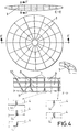
- the lenticular recipients (1) which together comprise the modulated liquid lens, will be manufactured of transparent materials susceptible to be moulded by any method of warping, blowing, etc., such as sheets of glass, organic plastic materials, inorganic materials or similar, with an appropriate thickness in accordance with the internal pressure and external conditions which they must withstand and of the resistance characteristics of the material used, adopting the adequate geometry; these lenticular recipients being assembled together in a self-supporting form or with the addition of a structure made of sections of the appropriate material which together form the intended modulated lens, as is represented in figure number 4,.
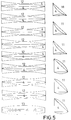
- the modular recipients (1) which constitute the modulated liquid lens, may in turn be subdivided horizontally (8), vertically or transversally in their interior, in any direction (9), in order to be able to be filled or emptied simultaneously or alternately with the refracting fluid (4), in accordance with the needs of obtaining different focal distances with one same modulated liquid lens, for which purpose the recipients will be provided with the necessary orifices and connections in their faces or joints (10), obtaining forms and optical combinations (as represented in figure number 5) such as the lenticular prism (11) in all its variants, the mixed or multiple convergent-divergent lens (12), and others (13), according to the different alternatives of filling or emptying of the configured recipients.
- any joints (14) between the different lenticular recipients (1) that may be necessary will be executed by means of the use of adhesive material, solderable material or moulds, which in turn provide sufficient tightness and durability of the set of recipients which comprise the modulated liquid lens, it being possible to use joints which are elastic, rigid, semi-rigid, of smelted materials, self-supporting or with the addition of a supporting structure, executed using the appropriate sections to permit the conformation of the modulated lens.
- the colour and texture of the aforementioned materials with which the lenticular recipients are constructed is in no way relevant, provided that they permit the concentration of the solar light with the greatest efficiency, it being possible to incorporate any material, product or anti-reflective device either on the surface or incorporated in the refracting fluid (4).
- the refracting fluid (4) may be comprised by gas, water or any other liquid, semi-liquid or solidifiable refracting component, and will have the appropriate composition to withstand the atmospheric and climatological conditions to which it is to be subjected, it being in this sense possible to incorporate anti-freeze, coolants or any other substance which contributes to the optimum conditions necessary.
- the assembly formed by the modulated lens and its supporting structure may be provided with whatever fastening, hinging or turning elements may be necessary, independently of whether the elements used are own or added, in order to facilitate its use, both static and dynamic.
- the parallel beam impinges on an absorber (26), after passing through a selective window (25), which is intended to minimize the heat losses of the absorber (26).
- the absorber (26) transfers the heat to the fluid in a primary circuit (27) which, by means of an exchanger, cedes the heat to a secondary fluid (28) which uses it for any use which requires high pressure and high temperature steam, being provided with at least one selective window and housed within a vacuum chamber, in order to minimize losses of heat by radiation.
- the modulated liquid lens (21) formed by different glass recipients, has the appropriate thickness and characteristics to permit the maximum transmissivity and the structural strength necessary to withstand the interior pressure of the fluid and the stresses derived from its constitution and method of fixture.
- the modulated liquid lens (21) is constituted on the basis of a plurality of lenticular recipients, positioned concentrically to a central lenticular disc (32) and mounted on a reticular structure (33), executed preferentially in steel or aluminium of high strength.
- the whole assembly described above may turn by means of turning mechanisms (30) for the perfect tracking of the solar trajectory, which, together with the previously delimited context, permits the movement of the divergent lens (22) and the liquid prism (23) along the curved structure (23) following the condensed focus, achieving the reception of the solar rays in the most suitable way.
- the solar energy condenser on a moving structure is provided with an element for the generation of heat by combustion (29) which can supplement the lack of solar energy in periods of low radiation or during the night and can be constituted in any way and by means of any application which is considered appropriate, such as an element, device or annex to the installation, powered by energies of any type.
- the condenser which will be hermetically sealed, will be provided with equipment for the recovery of residual heat (34) for different uses.
Landscapes
- Engineering & Computer Science (AREA)
- Physics & Mathematics (AREA)
- Chemical & Material Sciences (AREA)
- Sustainable Development (AREA)
- Sustainable Energy (AREA)
- Thermal Sciences (AREA)
- Life Sciences & Earth Sciences (AREA)
- Combustion & Propulsion (AREA)
- Mechanical Engineering (AREA)
- General Engineering & Computer Science (AREA)
- General Physics & Mathematics (AREA)
- Optics & Photonics (AREA)
- Photovoltaic Devices (AREA)
- Mechanical Light Control Or Optical Switches (AREA)
Abstract
A condenser of solar energy on a moving structure, with East-West solar tracking and a modulated liquid lens, the former consisting of a system capable of concentrating the solar energy (2) by the incorporation of one or several modulated liquid lenses (21), and the latter composed by the connection of different transparent lenticular recipients (1), capacitated for installation on a metallic structure of spherical or cylindrical shape which, by means of the action of a divergent lens (22) and a liquid prism (24), transmits the heat to the fluid in a primary circuit (27) which by means of a heat exchanger (28) provides the temperature necessary for the different energy uses.
Description
- This descriptive report refers to a condenser of solar energy which incorporates a large size modulated liquid lens, using the property possessed by fluids of refracting and concentrating light when they are delimited by curved transparent surfaces, i.e., this is a lens conformed by different transparent lenticular recipients of shapes, dimensions and curvatures which permit, in their combination, the configuration of a modulated liquid lens with a focal distance which is appropriate and capacitated to be placed on a moving or fixed structure, with this structure adjusted to the characteristics of the modulated liquid lens thus constituted, permitting its construction in large dimensions, without limitation of thicknesses and shapes, having at the same time the quality of being manufactured at low cost in comparison with other known lenses of similar optical characteristics, elaborated with other materials and providing the concentration of the solar flux corresponding to large surface areas.
- It is also the object of the invention to permit the condensation of solar rays of a certain surface area on a heat absorber, and to provide sufficient energy to the fluid which circulates through the secondary circuit thereof, in order to raise its temperature beyond its boiling point with the object of permitting its use as thermal fluid in an electricity production turbine, in a water desalinization plant or in any other application which requires steam of high enthalpy.
- The invention possesses a condensation system based on modulated liquid lenses which considerably cheapens the cost of its installation compared with conventional lenses, also being provided with a tracking and guidance system which permits the total harnessing of the impinging rays, which always act in the most efficient form in the heat exchanger.
- This invention has its field of application within the industry dedicated to the harnessing of solar energy by its concentration, both in the manufacturing of lenses, as elements and devices for that purpose, and within the optics industry and, in general, in all applications in which lenses of large dimensions are required, it being equally possible to use it in the industry dedicated to the manufacturing of condensers of solar energy.
- It is known that by means of the use of a transparent lenticular recipient with a refracting liquid in its interior, similar effects of concentration of solar light are achieved to those obtained with a conventional optical lens, but to date this physical principle has only been approached on a small scale, which is not viable for industrial usage due to its very high cost.
- Being the objective of this invention the harnessing of large magnitudes of solar flux, in order to obtain high temperatures and a great concentration of energy, it is indispensable to use lenses of large dimensions, of an appropriate design, which optically, and with a low manufacturing cost, permit an economically viable use for industrial purposes, such as the obtainment of electrical energy, desalinization, depuration, treatment of wastes, applications in the field of medicine, optics in general, production of hydrogen, cogeneration of energy, etc.
- The applicant also knows of the existence of patents which develop some of the elements which are used in condensers of solar energy on a moving structure, among which the following may be pointed out. Namely:
- Spanish Patent number 9101791, of 30th July 1991, which sets forth the idea of being able to concentrate the solar flux by means of lenses which have the particularity of being configured as lenticular recipients of transparent material which, when filled with a transparent fluid, semi-solid material or solidifiable material, refract the direct or previously reflected light in a way which is similar to that achieved with an ordinary lens, with the consequent cheapening of costs, integrating these ideas in a body which is materialized in the so-called "liquid lens".
- Spanish Patent number 9402313, of 10th November 1994, which basically touches upon the possibility that the mechanism capable of harnessing solar energy by means of the use of liquid lenses will be constituted by a moving or fixed supporting structure.
- Spanish Patent number 9502166, of 7th November 1995, which perfects the former, analysing some characteristics of the liquid lens.
- Spanish Patent number 9601033, of 8th May 1996, which defines the characteristics of a modulated liquid lens which permits the construction of liquid lenses of large size, adequate for the purposes of harnessing solar rays on large surface areas.
- Spanish Patent number 9700507, relating to a Modulated Liquid Lens on a moving structure, with solar tracking.
- The aforementioned patents characterize elements for harnessing and directing solar rays by means of the incorporation of liquid lenses or modulated liquid lenses, which will be integrating parts of the invention which comprises the subject matter of this descriptive report, this being a much broader conception and with a utility defined by its constitution.
- On the other hand, the applicant knows of the existence of systems which permit the harnessing of solar energy in order to produce electricity, potabilize water or even configure very high temperature ovens by means of the condensation of solar rays, but all of them incorporate reflecting elements of the type comprised by concave and flat mirrors and reflecting elements of the type comprised by solid lenses, constituted on the lines dictated by the use of materials such as glass or quartz, of very high weight, costly and not apt for configuring collectors of large dimensions.
- The evident solution to the problems existing in this field would be that of being provided with a condenser of solar energy fitted with modulated liquid lenses, of low weight, lower cost than the solid lenses, and structurally apt for the harnessing of large magnitudes of solar flux.
- At the same time it would be desirable also to be provided with a mechanism which orients the energy condenser towards the sun at all times, for the maximum harnessing of the solar flux.
- However, the applicant has no knowledge of the existence at the present time of an invention which is provided with all the characteristics indicated above as suitable.
- The condenser of solar energy which the invention proposes constitutes in itself an evident novelty within the field of application in which it is incorporated, as on the basis of a modulated liquid lens with fluid in its interior, of large dimensions, appropriate shapes and characteristics, capacitated to perform its function in an optimum manner, at a low manufacturing cost and to be used as a large collector of solar energy, placed on an appropriate structure, mobile with solar tracking or fixed without solar tracking, which permits the concentration of a large quantity of solar flux at high temperature.
- The modulated liquid lens which forms the subject matter of this invention can be constituted with lenticular recipients of different transparent materials capable of being moulded, such as sheets of glass, organic plastic materials, inorganic materials, and similar.
- The thickness of these sheets must be the appropriate in accordance with the internal pressure and external conditions which they have to withstand and the resistance characteristics of the material used.
- The surfaces of the modulated lens - curved, warped, flat or mixed, spherical or cylindrical, etc. - will be given in accordance with the type of focus which it is intended to obtain, i.e.: circular, elliptic, longitudinal, etc. and will have the curvature appropriate for the distance which it is projected to obtain in each case.
- The plan form of this modulated lens may be: circular, polygonal, elliptic, parabolic, etc., and will be in accordance with the needs of projection.
- The modulated liquid lens may be configured as a toric body of revolution, of total or partial development, of an appropriate section in accordance with its size and shape, which provides one or several centred focal points according to needs.
- When it is necessary to capture the flux of solar energy on an element or body in movement, use will be made of the complete toric modulated lens, or of total development, in the form of a dome or spherical cap, complete or flattened.
- If the harnessing is to be carried out in a static way, it will be possible to use the toric modulated liquid lens of partial development, whose dimensions will vary according to the needs of the surface area destined for harnessing.
- The construction of the modulated liquid lens will be carried out on the basis of one or several individual recipients, whose shape and size will depend on the total dimensions of the modulated liquid lens to be obtained, it being possible for these recipients to be communicated with each other by means of the necessary orifices and connections in their faces, in such a way as to permit their total or partial filling with the refracting liquid.
- With the aim of achieving several different focal distances with one single large size modulated lens, each one of the individual recipients which comprise the lens may in turn be horizontally divided in its interior, in order to be filled simultaneously or alternately, and thus may be divided vertically or transversally according to the needs of obtaining the adequate focal distances.
- As a consequence of this, it is possible to obtain shapes and optical combinations such as the lenticular prism, mixed or multiple lens, convergent-divergent lens, and others, on the basis of the different alternatives of filling or emptying of the configured recipients.
- It is also possible to obtain a single focal point with a non-homogenous lens or lens of compound shape and variable section.
- Any necessary joints between the different recipients will be executed by means of the use of adhesive material, solderable material or moulds, which in turn provide sufficient tightness and durability of the set of recipients which comprise the modulated liquid lens, it being possible to use joints which are elastic, rigid, semi-rigid, of smelted materials, self-supporting or with the addition of a supporting structure, executed using the appropriate sections to permit the conformation of the modulated lens.
- The modulated lens, constituted by a set of lenticular recipients assembled together, may adopt the usual shapes of lenses: convergent (biconvex, planoconvex, concave-convex) or divergent (concave, planoconcave, convex-concave).
- The colour and the texture of the aforementioned materials with which the lenticular recipients are constructed, is not in any way relevant, provided that they permit the concentration of the solar light with the greatest efficiency, it being possible to incorporate any material, product or anti-reflective device either on the surface or incorporated in the refracting fluid.
- The assembly formed by the modulated lens and its supporting structure may be provided with whatever fastening, hinging or turning elements may be necessary, independently of whether the elements used are own or added, in order to facilitate its use, both static and dynamic.
- The refracting fluid may be comprised by gas, water or any other refracting liquid, semi-liquid or solidifiable material, and will have the adequate composition to withstand the atmospheric and climatological conditions to which it is to be subjected, it being in this respect possible to incorporate anti-freeze, coolants or any other substance which contributes to the optimum conditions for its operation.
- The incorporation of the toric shape modulated lens of partial development to the moving structure permits the use of a purely electromechanical solar tracking system, of low cost, due to the high tolerance which this wide angle modulated lens provides, in the harnessing of large amounts of solar energy flux, with the consequent economic savings.
- Also object of the invention is the modulated liquid lens constituted by a series of recipients which configure a central lenticular disc and several lenticular crowns which surround it, all assembled by means of the provision of a structure which gives it a spherical or cylindrical shape (dome or vault).
- The characteristics of the modulated liquid lens permit it to behave in the same way as a conventional lens but with a clearly lower weight and thickness.
- In the vertical trajectory of the light source a liquid prism is provided which diverts by refraction the light beam towards a fixed point in the installation where the absorbent is located, the light source may also be diverted by a reflection system, all of which is arranged on a curved sliding rail.
- At the focus a divergent liquid lens is positioned, whose mission is to transform the light source into a beam of parallel rays, which is made to impinge upon one of the faces of the liquid prism or refracting plate for its diversion towards the absorbent.
- The assembly comprised by a divergent liquid lens and the liquid prism is provided with linear movement along the length of the sliding rail in order to permit the tracking of the light beam throughout its vertical path.
- The beam of parallel rays refracted from the liquid prism, impinges on an absorbent which contains a thermal plate which receives the solar energy and transmits the calorific energy to a circulating fluid; the chamber where the absorbent resides being provided with at least one selective window at its entrance to minimize the loss of energy by emittance, and being provided also with a vacuum chamber which prevents losses of heat.
- The receptor fluid, which receives the solar energy condensed on the absorbent, circulates through a primary circuit which has a heat exchanger which transfers the heat to a secondary circuit which contains the fluid destined for the production of electrical energy or any other use, process or procedure which requires the use of high pressure and high temperature steam.
- The condenser of solar energy is provided with a device or system for the East-West rotation of the assembly, which permits it to turn following the trajectory of the sun, and the assembly formed by the prism and the lens is provided also with equipment for tracking the light source.
- Finally, the invention is also provided with a secondary heat production circuit which supplements the aforementioned solar powered system with a combustion system using as fuel either gas, diesel, coal or any other commonly used fuel.
- In order to complement the description which is being given, and to assist in the obtainment of a better understanding of the characteristics of the invention, this descriptive report is accompanied, as an integral part of the same, by eleven pages of drawings, which with an illustrative and non-limiting character, represent the following:
- Figure number 1.- Shows the general diagram, cross section view of the subject matter of the invention, referring to the modulated liquid lens, condenser of solar energy, representing a large size modulated lens, of the convergent type, a graphic representation which is given by way of example, it being possible to give a diversity of similar representations, varying the configuration, which can present any type of cross section of convergent or divergent characteristics and the combinations of these.
- Figure number 2.- Corresponds to plan and perspective views of the toric section modulated lens of total and partial development.
- Figure number 3.- Represents horizontal and vertical cross sections of the toric form modulated lens of total or partial development and the prespective view of a cross-sectioned sector of this lens, as well as a detail in prespective view of one of the forms which can be adopted by the lenticular recipients.
- Figure number 4.- Corresponds to a plan and cross section diagram of a large size modulated lens of biconvex convergent type, comprised by different lenticular recipients and details of the assembly, joints and supporting structure of these recipients, as well as sealing of connections and filling and emptying orifices.
- Figure number 5.- Corresponds to a view of the different shapes and optical combinations on the basis of the configuration of the lenticular recipients and their filling alternatives, such as the lenticular prism and the mixed or multiple convergent-divergent lens and others.
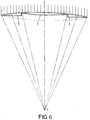
- Figure number 6.- Represents the diagram of a non-homogenous or compound shape modulated lens, of variable section.
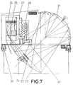
- Figure number 7.- Corresponds to a general diagram of the constitution of the solar energy condenser moving structure in which the modulated liquid lens is applied.
- Figure number 8.- Illustrates the different positions which may be acquired by the refracting liquid prism and the divergent liquid lens in the tracking of the solar rays.
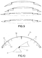
- Figure number 9.- Shows, by way of example, different modulated liquid lenses.
- Figure number 10.- Details the form or method of the joint between two adjacent sections of the modulated liquid lens.
- Figure number 11.- Refers to a plan and section view of the modulated liquid lens in
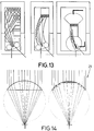
figure number 10. - Figure number 12.- Details the conversion of the light source into a beam of parallel rays by means of the divergent liquid lens, and their refraction by the liquid prism.
- Figure number 13.- Illustrates some possibilities of concentration of the solar energy within the absorbent.
- Figure number 14.- Shows, finally, the concentration of the solar flux by means of a conventional lens and using a modulated liquid lens, in it, the similitude between their focal distance and their notable difference in thickness can be seen.
- In view of
figures numbers figure number 1, comprised by a set of transparent lenticular recipients (1), of adequate types, dimensions and curvatures, which by means of the incorporation in their interior of a refracting fluid (4), permit the obtainment of an appropriate focal distance, providing the concentration, in one or two small size focuses, of the solar flux (2) corresponding to large surface areas, without limitation of thicknesses and shapes, being manufactured of different transparent materials, susceptible to moulding, it being possible for the modulated liquid lens to adopt the usual shapes of convergent or divergent lenses in all their types and it being capacitated to be placed on a moving structure with solar tracking or a fixed structure without solar tracking. - The modulated liquid lens as a whole may adopt any plan form: circular, polygonal, elliptic, parabolic, etc., depending on the needs of projection, it being possible to configure the lens by the connection of different toric bodies of revolution, generated by the sections of the lenticular recipients represented in
figure number 2, engendered by the surface comprised between the intersection of two non-concentric circles, turning on the axis of the exterior circle, totally or partially, being extendible in the same way when the interior circle is replaced by a straight or broken line turning on the axis of the exterior circle represented infigure number 3, in such a way that, when its development is complete, it may generate a body in the form of a spherical cap or dome, complete or flattened, without limitation of sizes, in accordance with the needs of harnessing of the solar flux. - The lenticular recipients (1), which together comprise the modulated liquid lens, will be manufactured of transparent materials susceptible to be moulded by any method of warping, blowing, etc., such as sheets of glass, organic plastic materials, inorganic materials or similar, with an appropriate thickness in accordance with the internal pressure and external conditions which they must withstand and of the resistance characteristics of the material used, adopting the adequate geometry; these lenticular recipients being assembled together in a self-supporting form or with the addition of a structure made of sections of the appropriate material which together form the intended modulated lens, as is represented in
figure number 4,. - The modular recipients (1), which constitute the modulated liquid lens, may in turn be subdivided horizontally (8), vertically or transversally in their interior, in any direction (9), in order to be able to be filled or emptied simultaneously or alternately with the refracting fluid (4), in accordance with the needs of obtaining different focal distances with one same modulated liquid lens, for which purpose the recipients will be provided with the necessary orifices and connections in their faces or joints (10), obtaining forms and optical combinations (as represented in figure number 5) such as the lenticular prism (11) in all its variants, the mixed or multiple convergent-divergent lens (12), and others (13), according to the different alternatives of filling or emptying of the configured recipients.
- The use of the lenticular recipients (1) described above permits the construction of the modulated liquid lens of non-homogenous or compound section, represented in
figure number 6, with a single focus (3). - Any joints (14) between the different lenticular recipients (1) that may be necessary will be executed by means of the use of adhesive material, solderable material or moulds, which in turn provide sufficient tightness and durability of the set of recipients which comprise the modulated liquid lens, it being possible to use joints which are elastic, rigid, semi-rigid, of smelted materials, self-supporting or with the addition of a supporting structure, executed using the appropriate sections to permit the conformation of the modulated lens.
- The colour and texture of the aforementioned materials with which the lenticular recipients are constructed is in no way relevant, provided that they permit the concentration of the solar light with the greatest efficiency, it being possible to incorporate any material, product or anti-reflective device either on the surface or incorporated in the refracting fluid (4).
- The refracting fluid (4) may be comprised by gas, water or any other liquid, semi-liquid or solidifiable refracting component, and will have the appropriate composition to withstand the atmospheric and climatological conditions to which it is to be subjected, it being in this sense possible to incorporate anti-freeze, coolants or any other substance which contributes to the optimum conditions necessary.
- The assembly formed by the modulated lens and its supporting structure may be provided with whatever fastening, hinging or turning elements may be necessary, independently of whether the elements used are own or added, in order to facilitate its use, both static and dynamic.
- The incorporation of the toric shape modulated lens of partial development (6) and (7) in the moving structure, permits, due to the high tolerance which this wide angle modulated liquid lens provides, the use of low-cost, purely electromechanical solar tracking equipment in the harnessing of large amounts of solar energy flux, with the consequent economic savings.
- Following
figure number 7, it is possible to observe the condenser of solar energy, which has one modulated liquid lens (21) which concentrates the solar rays at an interior point; however, at a point close to the focus, the beam is intercepted by a divergent liquid lens (22), which transforms it into a parallel beam which is diverted by the liquid prism (24) which moves along the curved structure (23) following the solar rays which change their angle of impingement in accordance with the movement of the sun. - The parallel beam impinges on an absorber (26), after passing through a selective window (25), which is intended to minimize the heat losses of the absorber (26).
- The absorber (26) transfers the heat to the fluid in a primary circuit (27) which, by means of an exchanger, cedes the heat to a secondary fluid (28) which uses it for any use which requires high pressure and high temperature steam, being provided with at least one selective window and housed within a vacuum chamber, in order to minimize losses of heat by radiation.
- The modulated liquid lens (21), formed by different glass recipients, has the appropriate thickness and characteristics to permit the maximum transmissivity and the structural strength necessary to withstand the interior pressure of the fluid and the stresses derived from its constitution and method of fixture.
- The modulated liquid lens (21) is constituted on the basis of a plurality of lenticular recipients, positioned concentrically to a central lenticular disc (32) and mounted on a reticular structure (33), executed preferentially in steel or aluminium of high strength.
- The advantages of the modulated liquid lenses compared with conventional solid lenses result from their low weight, reduced cost, short focal distance in relation with their dimensions, as well as the sharpness of their focus and the possibility of correcting the spherical aberration, since it is possible to vary the exit angle of the light rays.
- The whole assembly described above may turn by means of turning mechanisms (30) for the perfect tracking of the solar trajectory, which, together with the previously delimited context, permits the movement of the divergent lens (22) and the liquid prism (23) along the curved structure (23) following the condensed focus, achieving the reception of the solar rays in the most suitable way.
- The solar energy condenser on a moving structure is provided with an element for the generation of heat by combustion (29) which can supplement the lack of solar energy in periods of low radiation or during the night and can be constituted in any way and by means of any application which is considered appropriate, such as an element, device or annex to the installation, powered by energies of any type.
- Furthermore, the condenser, which will be hermetically sealed, will be provided with equipment for the recovery of residual heat (34) for different uses.
Claims (15)
- A modulated liquid lens, condenser of solar energy, comprised by transparent lenticular recipients (1) of the appropriate shapes, dimensions and curvatures, which permit the obtainment of an appropriate focal distance, providing the concentration of a reduced focus (3) of the solar flux (2) corresponding to large surface areas, without limitation of thicknesses and shapes, being manufactured on the basis of different lenticular recipients (1), transparent and susceptible to moulding, containing in their interior a refracting fluid (4), it being possible for the modulated liquid lens to adopt the usual convergent or divergent forms, the different lenticular recipients (1) which comprise it being assembled together (14), being capable of being placed on a moving structure with solar tracking or a fixed structure without solar tracking adjusted to the characteristics of the modulated liquid lens thus constituted.
- A modulated liquid lens, condenser of solar energy, in accordance with the first claim, characterized because it can adopt any plan form: circular, polygonal, elliptic, parabolic, according to the needs of projection, the lenticular recipients (1) being manufactured by means of the use of materials susceptible to moulding by any method, it being possible for said recipients to adopt the form of sheets of glass, organic plastic materials, inorganic materials and similar, with an appropriate thickness to withstand the internal pressure and the external conditions to which they are subjected and of the resistance characteristics of the material to be used.
- A new modulated liquid lens, condenser of solar energy, on a moving structure, in accordance with the first claim, characterized because the modulated liquid lens can be configured on the basis of the connection of several toric bodies of revolution generated by the section of the lenticular recipients, engendered by the surface area comprised between the intersection of two non-concentric circles turning on the axis of the exterior circle, totally or partially, being extendible also when the interior circle is substituted by a straight or broken line turning on the axis of the exterior circle of total development (5) or partial development (6) and (7), of an appropriate section in accordance with the size and shape provided by one or several focuses (3) centred according to needs, it being possible for said toric bodies to be of complete development, in the form of a dome or spherical cap, complete or flattened, without limitation of sizes.
- A new modulated liquid lens, condenser of solar energy, in accordance with the first claim, characterized because the lenticular recipients (1) which constitute the modulated liquid lens may in turn be subdivided horizontally (8), vertically or transversally (9) in their interior in order to be filled or emptied simultaneously or alternately with the refracting fluid (4), according to the needs of obtaining different focal distances with one same lens; said recipients being provided with the necessary orifices and connections in their faces (10), it being possible to obtain one single focus with a modulated lens of a non-homogenous or compound section.
- A new modulated liquid lens, condenser of solar energy, in accordance with the first claim, characterized because the joints (14) which it may be necessary to make between the different lenticular recipients will be executed by means of the use of adhesive materials, solderable materials or moulds, which provide sufficient tightness and durability of the modulated liquid lens, it being possible to use joints which are elastic, rigid, semi-rigid, of smelted materials, self-supporting or with the addition of a supporting structure, executed using the appropriate sections.
- A new modulated liquid lens, condenser of solar energy, in accordance with the first claim, characterized because the colour and texture of the lenticular recipients (1), manufactured with any of the indicated materials, will permit the concentration of solar light with the maximum efficiency, it being possible to incorporate any material, product or anti-reflective device, both on the surface and within the refracting fluid (4).
- A new modulated liquid lens, condenser of solar energy, in accordance with the first claim, characterized because the refracting fluid (4) will have the appropriate composition to withstand the atmospheric and climatological conditions to which it is to be subjected, it being possible to incorporate anti-freeze, coolants or any other substance which complies with optimum conditions and which does not impede or improve the refraction.
- A new modulated liquid lens, condenser of solar energy, in accordance with the first claim, characterized by being provided with whatever fastening, hinging or turning elements as are necessary to facilitate its use, both static or dynamic, in the harnessing of the solar flux (2).
- A new modulated liquid lens, condenser of solar energy, in accordance with the first claim, characterized by the incorporation in the moving structure of a toric shape modulated lens of partial development (6) and (7), which permits the use of an electromechanical solar tracking equipment, as this is a lens of a wide angle capacity.
- A new modulated liquid lens, condenser of solar energy, in accordance with the first claim, characterized by the subdivision of the lenticular recipients (1), horizontally (8).
- A new modulated liquid lens, condenser of solar energy, in accordance with the first claim, characterized because the refracting fluid (4) may be comprised by gas, water or any other refracting liquid, semi-liquid or solidifiable material.
- A condenser of solar energy on moving structure, provided with one or several modulated liquid lenses (21), concentrators of solar rays, being provided in their interior with a divergent lens (22) which intercepts the light source and converts it into a beam of parallel rays which impinge upon a liquid prism (24) which refracts the beam towards an absorbent (26) which heats up and cedes the energy to the fluid which circulates through a primary circuit (27) which, by means of an exchanger (28), transmits the heat to the secondary fluid, evaporating it at high pressure and temperature for its energy application, and being provided with a sliding rail (23) along which the assembly formed by the prism (24) and the divergent lens (22) moves, tracking the light source by means of the action of an appropriate tracking system.
- A condenser of solar energy, in accordance with the twelfth claim, characterized because the absorber (26) is provided with a vacuum chamber which surrounds it; it also being provided with at least one selective window (25) communicated with the interior of the absorber (26), permitting the passing of the light beam which comes from the liquid prism (24).
- A condenser of solar energy on a moving structure, in accordance with the twelfth and thirteenth claims, characterized by being able to perform a turning movement tracking the solar trajectory, by means of the incorporation of turning elements (30).
- A modulated liquid lens, condenser of solar energy, in accordance with the first to eleventh claims, both inclusive, characterized by being constituted by a series of recipients which conform a central lenticular disc and several lenticular crowns which surround it, all of them assembled together by means of the provision of a reticular structure which gives it a spherical or cylindrical form, conforming it as a dome or vault respectively.
Applications Claiming Priority (5)
| Application Number | Priority Date | Filing Date | Title |
|---|---|---|---|
| ES9601033 | 1996-05-08 | ||
| ES09601033A ES2113317B1 (en) | 1996-05-08 | 1996-05-08 | NEW MODULATED SOLAR ENERGY CONDENSER LENS. |
| ES9700507 | 1997-03-07 | ||
| ES09700507A ES2123450B1 (en) | 1997-03-07 | 1997-03-07 | NEW SOLAR ENERGY CAPACITOR ON MOBILE STRUCTURE. |
| PCT/ES1997/000119 WO1997042452A1 (en) | 1996-05-08 | 1997-05-08 | New liquid modulated lens for condensing solar energy |
Publications (1)
| Publication Number | Publication Date |
|---|---|
| EP0840075A1 true EP0840075A1 (en) | 1998-05-06 |
Family
ID=26154966
Family Applications (1)
| Application Number | Title | Priority Date | Filing Date |
|---|---|---|---|
| EP97918165A Withdrawn EP0840075A1 (en) | 1996-05-08 | 1997-05-08 | New liquid modulated lens for condensing solar energy |
Country Status (8)
| Country | Link |
|---|---|
| US (1) | US6124980A (en) |
| EP (1) | EP0840075A1 (en) |
| JP (1) | JP2000500884A (en) |
| CN (1) | CN1196787A (en) |
| AU (1) | AU2638997A (en) |
| BR (1) | BR9702249A (en) |
| IL (1) | IL122881A0 (en) |
| WO (1) | WO1997042452A1 (en) |
Cited By (3)
| Publication number | Priority date | Publication date | Assignee | Title |
|---|---|---|---|---|
| WO2006079671A1 (en) * | 2005-01-25 | 2006-08-03 | Roberto Santander Cerbell | Liquid sun lens |
| DE102007040922A1 (en) * | 2007-08-30 | 2009-03-05 | Pittroff, Elmar | Solar power plant, has set of large lenses for generating current to drive turbine, where heat radiation of sun is bundled through lenses attached on set of masts in glass boiler filled with water |
| EP3470751A4 (en) * | 2016-06-09 | 2020-02-12 | Santander Y Santana, S.L. | Solar energy condenser system with a cylindrical liquid lens and "black body" absorber |
Families Citing this family (43)
| Publication number | Priority date | Publication date | Assignee | Title |
|---|---|---|---|---|
| US6355144B1 (en) * | 1998-03-05 | 2002-03-12 | Leonard Murrey Weinstein | High output solar water distillation system |
| ES2143951B1 (en) * | 1998-05-18 | 2000-12-01 | Santander Cerbell Roberto | MODULATED LIQUID LENS WITHOUT SPHERICAL ABERRATION PROVIDED WITH MEANS FOR THE ABSORPTION OF THE SOLAR ENERGY CONDENSER. |
| ES2151418B1 (en) * | 1998-09-15 | 2001-07-16 | Cerbell Roberto Santander | THERMAL PLATE FOR THE ABSORPTION OF HIGH TEMPERATURES GENERATED BY A SOLAR ENERGY CONDENSER. |
| US6504654B1 (en) * | 1998-05-18 | 2003-01-07 | Roberto Santander Cerbell | Modulated liquid lens without spherical aberration having means for absorbing the solar energy condenser and provided with a heat plate for the absorption of high temperatures |
| US20030060878A1 (en) | 2001-08-31 | 2003-03-27 | Shadduck John H. | Intraocular lens system and method for power adjustment |
| US8048155B2 (en) | 2002-02-02 | 2011-11-01 | Powervision, Inc. | Intraocular implant devices |
| US6966649B2 (en) * | 2002-08-12 | 2005-11-22 | John H Shadduck | Adaptive optic lens system and method of use |
| CA2506753A1 (en) | 2002-11-20 | 2004-06-03 | Victor Esch | Lens system and method for power adjustment |
| US8361145B2 (en) | 2002-12-12 | 2013-01-29 | Powervision, Inc. | Accommodating intraocular lens system having circumferential haptic support and method |
| US7217288B2 (en) | 2002-12-12 | 2007-05-15 | Powervision, Inc. | Accommodating intraocular lens having peripherally actuated deflectable surface and method |
| US8328869B2 (en) | 2002-12-12 | 2012-12-11 | Powervision, Inc. | Accommodating intraocular lenses and methods of use |
| JP4480585B2 (en) * | 2002-12-12 | 2010-06-16 | パワービジョン, インコーポレイテッド | Intraocular lens adjustment and method |
| EP1569581A4 (en) | 2002-12-12 | 2006-09-20 | Powervision | Lens system for power adjustment using micropumps |
| US7637947B2 (en) | 2002-12-12 | 2009-12-29 | Powervision, Inc. | Accommodating intraocular lens system having spherical aberration compensation and method |
| US10835373B2 (en) | 2002-12-12 | 2020-11-17 | Alcon Inc. | Accommodating intraocular lenses and methods of use |
| EP1599748A4 (en) | 2003-03-06 | 2007-10-24 | John H Shadduck | Adaptive optic lens and method of making |
| US9872763B2 (en) | 2004-10-22 | 2018-01-23 | Powervision, Inc. | Accommodating intraocular lenses |
| EP1953573A1 (en) * | 2007-02-05 | 2008-08-06 | Paul & Charlene Investment Inc. | A liquid inserted lens and solar panel focusing system |
| AU2008218313B2 (en) | 2007-02-21 | 2014-01-09 | Alcon Inc. | Polymeric materials suitable for ophthalmic devices and methods of manufacture |
| US8968396B2 (en) | 2007-07-23 | 2015-03-03 | Powervision, Inc. | Intraocular lens delivery systems and methods of use |
| WO2009015226A2 (en) | 2007-07-23 | 2009-01-29 | Powervision, Inc. | Accommodating intraocular lenses and methods of use |
| EP2178462B1 (en) | 2007-07-23 | 2014-04-02 | PowerVision, Inc. | Post-implant lens power modification |
| US8314927B2 (en) | 2007-07-23 | 2012-11-20 | Powervision, Inc. | Systems and methods for testing intraocular lenses |
| EP2647353B1 (en) | 2007-07-23 | 2014-12-31 | PowerVision, Inc. | Lens delivery system |
| CN101546032B (en) * | 2008-06-11 | 2012-04-11 | 冯益安 | Passive multifunctional spherical surface or cylindrical surface optical collector |
| US10299913B2 (en) | 2009-01-09 | 2019-05-28 | Powervision, Inc. | Accommodating intraocular lenses and methods of use |
| MX2011011370A (en) * | 2009-04-27 | 2012-01-20 | Sun Edge LLC | Non-imaging light concentrator. |
| EP2473138A4 (en) | 2009-08-31 | 2017-08-16 | PowerVision, Inc. | Lens capsule size estimation |
| JP2013520291A (en) | 2010-02-23 | 2013-06-06 | パワーヴィジョン・インコーポレーテッド | Liquid for accommodation type intraocular lens |
| WO2012006616A2 (en) | 2010-07-09 | 2012-01-12 | Powervision, Inc. | Intraocular lens delivery devices and methods of use |
| JP6071995B2 (en) | 2011-03-24 | 2017-02-01 | パワーヴィジョン・インコーポレーテッド | Intraocular lens loading system and method of use |
| DE102011113130B3 (en) * | 2011-09-14 | 2013-01-24 | Heraeus Quarzglas Gmbh & Co. Kg | Solar radiation receiver with a quartz glass entrance window |
| US10433949B2 (en) | 2011-11-08 | 2019-10-08 | Powervision, Inc. | Accommodating intraocular lenses |
| US9212829B1 (en) * | 2012-06-27 | 2015-12-15 | Lockheed Martin Corporation | Solar heat collector with internal focal points |
| DE102012024369A1 (en) * | 2012-12-02 | 2014-03-20 | Ralf Hoyer | Solar system for conversion of solar radiation energy into electrical energy for heating water, has collecting lenses with hollow lens halves connected by hinge, and light and heat sensitive elements arranged as photo cells in lens halves |
| EP3785668A1 (en) | 2013-03-15 | 2021-03-03 | Alcon Inc. | Intraocular lens storage and loading devices and methods of use |
| GB201413710D0 (en) * | 2014-08-01 | 2014-09-17 | Carding Spec Canada | Solar energy concentrator apparatus |
| WO2017079733A1 (en) | 2015-11-06 | 2017-05-11 | Powervision, Inc. | Accommodating intraocular lenses and methods of manufacturing |
| US10253983B1 (en) | 2017-03-28 | 2019-04-09 | Randy Wolf | Fire-starting canteen |
| JP6829494B2 (en) * | 2017-12-06 | 2021-02-10 | 有限会社手島通商 | Irradiation device |
| ES2750704A1 (en) * | 2018-09-26 | 2020-03-26 | Villanueva Francisco Manuel Gallego | SOLAR ENERGY CONCENTRATOR (Machine-translation by Google Translate, not legally binding) |
| US11660182B2 (en) | 2019-10-04 | 2023-05-30 | Alcon Inc. | Adjustable intraocular lenses and methods of post-operatively adjusting intraocular lenses |
| CN112875786A (en) * | 2021-01-25 | 2021-06-01 | 南京航空航天大学 | Seawater desalination device with electrowetting lens solar thermal collector and working method |
Family Cites Families (5)
| Publication number | Priority date | Publication date | Assignee | Title |
|---|---|---|---|---|
| SE401257B (en) * | 1976-11-19 | 1978-04-24 | Bergkvist Lars A | DEVICE FOR HEATING A VETSIC BY SOLAR ENERGY |
| FR2412859A1 (en) * | 1977-12-23 | 1979-07-20 | Goldie Alain | Photovoltaic optical cell replacing solid lenses and prisms - has clear or coloured liq. or gel within two transparent walls sealed at their perimeters |
| US4249516A (en) * | 1979-01-24 | 1981-02-10 | North American Utility Construction Corp. | Solar energy collection |
| FR2464439A1 (en) * | 1979-08-30 | 1981-03-06 | Perrot Roland | Collector for solar energy - has water filled preformed plastics bag as lens to converge rays onto reflector and solar panel |
| AU3846995A (en) * | 1994-11-10 | 1996-06-06 | Roberto Santander Cerbell | New solar energy condenser |
-
1997
- 1997-05-08 JP JP9539563A patent/JP2000500884A/en active Pending
- 1997-05-08 EP EP97918165A patent/EP0840075A1/en not_active Withdrawn
- 1997-05-08 WO PCT/ES1997/000119 patent/WO1997042452A1/en not_active Application Discontinuation
- 1997-05-08 US US08/981,977 patent/US6124980A/en not_active Expired - Fee Related
- 1997-05-08 AU AU26389/97A patent/AU2638997A/en not_active Abandoned
- 1997-05-08 CN CN97190823A patent/CN1196787A/en active Pending
- 1997-05-08 IL IL12288197A patent/IL122881A0/en unknown
- 1997-05-08 BR BR9702249-7A patent/BR9702249A/en not_active Application Discontinuation
Non-Patent Citations (1)
| Title |
|---|
| See references of WO9742452A1 * |
Cited By (6)
| Publication number | Priority date | Publication date | Assignee | Title |
|---|---|---|---|---|
| WO2006079671A1 (en) * | 2005-01-25 | 2006-08-03 | Roberto Santander Cerbell | Liquid sun lens |
| ES2281231A1 (en) * | 2005-01-25 | 2007-09-16 | Roberto Santander Cerbell | Liquid sun lens |
| US7580196B2 (en) | 2005-01-25 | 2009-08-25 | Roberto Santander Cerbell | Liquid solar lens |
| DE102007040922A1 (en) * | 2007-08-30 | 2009-03-05 | Pittroff, Elmar | Solar power plant, has set of large lenses for generating current to drive turbine, where heat radiation of sun is bundled through lenses attached on set of masts in glass boiler filled with water |
| DE102007040922B4 (en) * | 2007-08-30 | 2014-01-16 | Kurt Elmar Pittroff | Solar power plant |
| EP3470751A4 (en) * | 2016-06-09 | 2020-02-12 | Santander Y Santana, S.L. | Solar energy condenser system with a cylindrical liquid lens and "black body" absorber |
Also Published As
| Publication number | Publication date |
|---|---|
| CN1196787A (en) | 1998-10-21 |
| MX9800268A (en) | 1998-09-30 |
| US6124980A (en) | 2000-09-26 |
| AU2638997A (en) | 1997-11-26 |
| IL122881A0 (en) | 1998-08-16 |
| WO1997042452A1 (en) | 1997-11-13 |
| BR9702249A (en) | 1999-12-28 |
| JP2000500884A (en) | 2000-01-25 |
Similar Documents
| Publication | Publication Date | Title |
|---|---|---|
| US6124980A (en) | Liquid modular lens for condensing solar energy | |
| US6384320B1 (en) | Solar compound concentrator of electric power generation system for residential homes | |
| US6620995B2 (en) | Non-imaging system for radiant energy flux transformation | |
| US6971756B2 (en) | Apparatus for collecting and converting radiant energy | |
| Buck et al. | Solar-hybrid gas turbine-based power tower systems (REFOS) | |
| US4148300A (en) | Solar radiation energy concentrator | |
| US4069812A (en) | Solar concentrator and energy collection system | |
| US4209222A (en) | Installation for utilizing solar energy with wavelength selective reflector | |
| US4043315A (en) | Solar heat collector | |
| ES2552645T3 (en) | Solar concentrator configuration with improved manufacturability and efficiency | |
| Thakkar et al. | Performance analysis methodology for parabolic dish solar concentrators for process heating using thermic fluid | |
| US4230094A (en) | Solar concentrator | |
| US20160079461A1 (en) | Solar generator with focusing optics including toroidal arc lenses | |
| US4341204A (en) | Solar energy collector | |
| Gunther et al. | Solar dish technology | |
| US4305383A (en) | Solar energy collector | |
| US4146408A (en) | Aspherical solar cell concentrator | |
| Dang | Concentrators: a review | |
| CN104422154A (en) | Disc type solar concentrating system | |
| CN104990285A (en) | Trackless solar condenser | |
| Suyanto et al. | A review of linear Fresnel reflector technology for heating sulphur liquid in nickel processing industry | |
| US4341203A (en) | Solar energy collector | |
| EP3470751B1 (en) | Solar energy condenser system | |
| JP2000056102A (en) | Condensing lens and light converging method using the condensing lens | |
| CA1108952A (en) | Solar concentrator and energy collection system |
Legal Events
| Date | Code | Title | Description |
|---|---|---|---|
| PUAI | Public reference made under article 153(3) epc to a published international application that has entered the european phase |
Free format text: ORIGINAL CODE: 0009012 |
|
| AK | Designated contracting states |
Kind code of ref document: A1 Designated state(s): AT BE CH DE DK FI FR GB GR IE IT LI LU MC NL PT SE |
|
| 17P | Request for examination filed |
Effective date: 19980916 |
|
| 17Q | First examination report despatched |
Effective date: 20010212 |
|
| STAA | Information on the status of an ep patent application or granted ep patent |
Free format text: STATUS: THE APPLICATION IS DEEMED TO BE WITHDRAWN |
|
| 18D | Application deemed to be withdrawn |
Effective date: 20010623 |