EP0838610A2 - Drive for rotating device like a roll, shaft or similar - Google Patents
Drive for rotating device like a roll, shaft or similar Download PDFInfo
- Publication number
- EP0838610A2 EP0838610A2 EP97121512A EP97121512A EP0838610A2 EP 0838610 A2 EP0838610 A2 EP 0838610A2 EP 97121512 A EP97121512 A EP 97121512A EP 97121512 A EP97121512 A EP 97121512A EP 0838610 A2 EP0838610 A2 EP 0838610A2
- Authority
- EP
- European Patent Office
- Prior art keywords
- lever
- gear
- drive
- fragrance
- drive according
- Prior art date
- Legal status (The legal status is an assumption and is not a legal conclusion. Google has not performed a legal analysis and makes no representation as to the accuracy of the status listed.)
- Granted
Links
Images


Classifications
-
- F—MECHANICAL ENGINEERING; LIGHTING; HEATING; WEAPONS; BLASTING
- F16—ENGINEERING ELEMENTS AND UNITS; GENERAL MEASURES FOR PRODUCING AND MAINTAINING EFFECTIVE FUNCTIONING OF MACHINES OR INSTALLATIONS; THERMAL INSULATION IN GENERAL
- F16H—GEARING
- F16H31/00—Other gearings with freewheeling members or other intermittently driving members
- F16H31/003—Step-by-step mechanisms for rotary motion
- F16H31/004—Step-by-step mechanisms for rotary motion with pawls driven by a rotary cam
-
- F—MECHANICAL ENGINEERING; LIGHTING; HEATING; WEAPONS; BLASTING
- F24—HEATING; RANGES; VENTILATING
- F24F—AIR-CONDITIONING; AIR-HUMIDIFICATION; VENTILATION; USE OF AIR CURRENTS FOR SCREENING
- F24F3/00—Air-conditioning systems in which conditioned primary air is supplied from one or more central stations to distributing units in the rooms or spaces where it may receive secondary treatment; Apparatus specially designed for such systems
- F24F3/12—Air-conditioning systems in which conditioned primary air is supplied from one or more central stations to distributing units in the rooms or spaces where it may receive secondary treatment; Apparatus specially designed for such systems characterised by the treatment of the air otherwise than by heating and cooling
-
- F—MECHANICAL ENGINEERING; LIGHTING; HEATING; WEAPONS; BLASTING
- F24—HEATING; RANGES; VENTILATING
- F24F—AIR-CONDITIONING; AIR-HUMIDIFICATION; VENTILATION; USE OF AIR CURRENTS FOR SCREENING
- F24F8/00—Treatment, e.g. purification, of air supplied to human living or working spaces otherwise than by heating, cooling, humidifying or drying
- F24F8/50—Treatment, e.g. purification, of air supplied to human living or working spaces otherwise than by heating, cooling, humidifying or drying by odorisation
-
- A—HUMAN NECESSITIES
- A47—FURNITURE; DOMESTIC ARTICLES OR APPLIANCES; COFFEE MILLS; SPICE MILLS; SUCTION CLEANERS IN GENERAL
- A47K—SANITARY EQUIPMENT NOT OTHERWISE PROVIDED FOR; TOILET ACCESSORIES
- A47K17/00—Other equipment, e.g. separate apparatus for deodorising, disinfecting or cleaning devices without flushing for toilet bowls, seats or covers; Holders for toilet brushes
-
- A—HUMAN NECESSITIES
- A61—MEDICAL OR VETERINARY SCIENCE; HYGIENE
- A61L—METHODS OR APPARATUS FOR STERILISING MATERIALS OR OBJECTS IN GENERAL; DISINFECTION, STERILISATION OR DEODORISATION OF AIR; CHEMICAL ASPECTS OF BANDAGES, DRESSINGS, ABSORBENT PADS OR SURGICAL ARTICLES; MATERIALS FOR BANDAGES, DRESSINGS, ABSORBENT PADS OR SURGICAL ARTICLES
- A61L9/00—Disinfection, sterilisation or deodorisation of air
- A61L9/015—Disinfection, sterilisation or deodorisation of air using gaseous or vaporous substances, e.g. ozone
- A61L9/04—Disinfection, sterilisation or deodorisation of air using gaseous or vaporous substances, e.g. ozone using substances evaporated in the air without heating
- A61L9/12—Apparatus, e.g. holders, therefor
-
- F—MECHANICAL ENGINEERING; LIGHTING; HEATING; WEAPONS; BLASTING
- F16—ENGINEERING ELEMENTS AND UNITS; GENERAL MEASURES FOR PRODUCING AND MAINTAINING EFFECTIVE FUNCTIONING OF MACHINES OR INSTALLATIONS; THERMAL INSULATION IN GENERAL
- F16H—GEARING
- F16H31/00—Other gearings with freewheeling members or other intermittently driving members
Definitions
- the invention relates to a drive for a rotating Object according to the preamble of claim 1.
- the invention has for its object a to create insensitive drive, which is also a easy separation of drive and driven means, e.g. B. plate stack allowed.
- This task is based on a drive according to the preamble of claim 1 by the characterizing features of claim 1 solved.
- the lever is preferably oriented and trained that he with his tip pointing to the gear engages in the gear and this tip in any position the lever is facing down.
- the device for storage and Guide the lever set up so that it is between two forward movements of the lever taking place Backward movement allowed, at which the lever is no longer is in engagement with the gear and this is not touched.
- the lever can continuously rotate the gear Drive direction of rotation.
- a ratchet drive can be dispensed with, which according to Art a ratchet in the backward movement with his in the Forward movement in the gear engaging pawl over the Teeth of the gear slip.
- a ratchet drive additionally required movable
- it becomes a component in living spaces disturbing noise development of a ratchet drive completely avoided.
- the device for storage and guidance comprises of the lever sliding surfaces that are attached to the lever itself and a bracket with guide surfaces.
- the lever is at one end with a rotating drive shaft connected eccentrically.
- a rotating shaft turns the lever into one at the same time Panning and translational movements offset each other are superimposed.
- the Lever tip can be effected.
- the forms of Sliding or guiding surfaces and the eccentricity of the Lever drive can be coordinated.
- two in a drive according to the invention Provided levers that alternately engage the gear.
- there is always a lever in engagement with the Gear so that this is not only driven, but also against any unwanted further movement, for example against turning back the rotating object after the Swiveling a lever tip out of the gearwheel, locked is.
- the rotation of the rotating object is thus constantly controlled mechanically by the lever drive and controlled.
- the two levers are preferably offset at 180 ° the same drive shaft articulated eccentrically. If both Have levers of the same shape and in slide corresponding guide surfaces, they perform accordingly identical forward and backward movements, which are offset in time by half a cycle length be performed.
- the drive shaft for the eccentric drive of the lever with one Worm wheel equipped in which a snail engages.
- extreme translations are possible especially when used in an inventive Fragrance evaporator, where a motor for the fan and the Rotation of the plate stack is used is necessary.
- a worm wheel drive provides a so-called self-locking gear, which, in conjunction with the Two-lever system, in which there is always a lever with the Gear of the rotating object is engaged, locking the rotating object, for example, a stack of disks with the power off Drive results.
- the worm is preferably connected via an elastic coupling connected to the drive shaft of an engine. This takes the drive shaft is not completely in line with the Standing shaft of snail. Larger tolerances in the Manufacture of a drive according to the invention are here possible, which among other things a cost saving brings.
- the transmission housing 9 is driven by a transmission drive shaft 10 interspersed with an elastic coupling 11 with a Motor drive shaft 12 of an electric motor 13 is connected. On the motor drive shaft 12 is an impeller 14 as Fan attached.
- the plate stack 4 is with its axis 5 in the End faces of a fragrance tray 15 shown rotatable stored.
- the fragrance tray 15 is in a sliding Drawer holder 16, on which, as not shown, the opening flap 3 can also be pivoted on its axis of rotation 17 is attached.
- FIGS 2 and 3 show an inventive Lever drive in an enlarged view.
- a front lever 7 is shown here with solid lines, while a second lever 7 'located behind the lever 7 with dotted lines is marked.
- the worm wheel 21 is rotationally fixed with one in Figures 2 and 3 not closer shown, but recognizable in Fig. 4
- Eccentric drive shaft 23 rotatably connected or in this incorporated.
- everyone Levers 7 and 7 ' are each with an upper 25 and lower 26 provided sliding surface. These are on the top 27 and lower 28 guide surfaces in the gear housing 9 are incorporated.
- a liquid fragrance In operation of the fragrance evaporator 1 is in the Perfume tray 15, as with line F as the liquid level is shown, a liquid fragrance. Within the Fragrance is partly a stack of plates 4. This is mounted rotatably about its axis 5 in the fragrance tray 15. He is on the lever 7, 7 'and the gear 6 in one Offset rotary movement. Here comes the fragrance wetted surface of the plate stack 4 with the air in Evaporation chamber 30 in contact, so that the fragrance of the surface into the air of the evaporation space 30 evaporates.
- the Flap 3 as shown in Fig. 2, down be folded down and the fragrance tray 15 on the Drawer bracket 16 can be pulled out. Of the Plate stack 4 remains in the fragrance tray 15 stored. Then the removable cassette 18, the Fragrance tray 15 together with its plate stack 4 comprises the drawer holder 16 can be removed and with a Cassette cover 19 are closed. This removable cassette 18 is thus ready for longer storage or for one Transport. Another identical exchangeable cassette or the same removable cassette can then be put back into the Fragrance evaporator 1 used in reverse order will.
- the drive for the plate stack 4 is done via the Gear 6 and the levers 7, 7 '.
- the levers 7, 7 ' are with With the help of the electric motor 13, which also drives the impeller 14, driven. This is done via the socket 29 of the Impeller 14 and the flexible coupling 11, whereby the Transmission drive shaft 10 is driven.
- FIGS. 2 + 3 show the levers 7, 7 'in different positions during the drive process, in which the plate stack 4 is rotated in the direction of arrow P 2 . Since the deflection of the eccentrics 24, 24 'is offset by 180 ° relative to the central axis M of the eccentric drive shaft 23, ie the central axes R, R' of the eccentrics 24, 24 'and the central axis M of the eccentric drive shaft 23 lie on a straight line the movement of the lever 7 'offset by half a movement cycle to the movement of the lever 7. As a result, there is at least one lever tip 8 in engagement of the gear 6, so that this is not only carried in the direction P 2 , but also in every position of the drive opposite other movements, for example a turning back against the direction of rotation of P 2 is locked.
- the drive shown for the plate stack 4 can be also outside of a fragrance evaporator according to the invention deploy.
- the system shown can be easily also in the version described below.
- Fig. 5 apply to any rotating object where a Drive system according to the invention offers advantages. This can especially the case with chemical production plants, where also rolls, shafts or the like are often inside of a liquid bath have to turn, and thus also the problem arises that the drive is not compatible with the aggressive liquid or only in touch may come.
- FIG. 5 is another embodiment of a Drive shown according to the invention.
- the lever drives 33 correspond to the previous simple lever drives described above. she are via a common screw 22 and the two Worm wheels 21, 21 'driven.
- the impeller 14 and the Electric motor arranged with a vertical axis.
Abstract
Description
Die Erfindung betrifft einen Antrieb für einen rotierenden
Gegenstand nach dem Oberbegriff des Anspruchs 1.The invention relates to a drive for a rotating
Object according to the preamble of
Beim Antrieb von Walzen, Wellen oder dergleichen, insbesondere auch beim Antrieb eines Plattenstapels eines Luftbefeuchtungs- und Reinigungsgerätes, eines Duftverdunsters oder dergleichen bei welchem der Plattenstapel innerhalb einer Flüssigkeit rotiert, treten immer wieder Probleme wegen Verunreinigungen des Getriebes durch die entsprechende Flüssigkeit auf.When driving rollers, shafts or the like, especially when driving a stack of plates Humidification and cleaning device, one Fragrance evaporator or the like in which the Rotate plate stack within a liquid, kick problems due to contamination of the gearbox through the appropriate liquid.
Dies ist insbesondere dann von Nachteil, wenn es sich um aggressive Flüssigkeiten handelt, z. B. bei einem Duftverdunster liegen derartige Flüssigkeiten beispielsweise in Form von ätherischen Ölen vor. Generell stellt sich dieses Problem jedoch beispielsweise auch im Bereich der Chemie, wo häufig mit aggressiven Flüssigkeiten, insbesondere Säuren und Laugen, hantiert wird.This is particularly disadvantageous if it is aggressive liquids, e.g. B. at one Such liquids are, for example, fragrance evaporators in the form of essential oils. Generally this turns out Problem, for example, also in the field of chemistry, where often with aggressive liquids, especially acids and Lye, is handled.
Umfangreiche Abdichtungsmaßnahmen der Getriebeeinheit führen nicht immer zum gewünschten Erfolg. Häufig bleibt als einzige Lösungsmöglichkeit, sämtliche Getriebekomponenten aus Materialien herzustellen, die gegenüber den verwendeten aggressiven Flüssigkeiten resistent sind.Carry out extensive sealing measures for the gear unit not always the desired success. Often remains the only one Possible solution, all transmission components To produce materials that are different from those used are resistant to aggressive liquids.
Dies zieht in der Regel einen erhöhten Kostenaufwand nach sich, wobei immer noch das Problem verbleibt, daß die Getriebeeinheit durch die jeweils verwendete Flüssigkeit verschmutzt wird.This usually increases costs itself, with the problem that the Gear unit through the liquid used in each case becomes dirty.
Insbesondere beim Wechsel der Flüssigkeit, d. h. z. B. bei einem Duftverdunster bei einem Wechsel des Duftstoffbades, kann es zu unerwünschten Vermischungen von Flüssigkeiten kommen. Nicht zuletzt bei chemischen Produktionsanlagen kann es hierbei sogar zu unerwünschten chemischen Reaktionen kommen, sofern das Getriebe nicht äußerst sorgfältig gereinigt wird.Especially when changing the liquid, i.e. H. e.g. B. at a fragrance evaporator when changing the fragrance bath, it can lead to undesirable mixing of liquids come. Not least with chemical production plants this even leads to undesired chemical reactions come unless the gearbox is extremely careful is cleaned.
Der Erfindung liegt die Aufgabe zugrunde, einen
unempfindlichen Antrieb zu schaffen, der auch eine
problemlose Trennung von Antrieb und angetriebenen Mittel, z.
B. Plattenstapel, erlaubt. Diese Aufgabe wird ausgehend von
einem Antrieb nach dem Oberbegriff des Anspruchs 1 durch die
kennzeichnenden Merkmale des Anspruchs 1 gelöst.The invention has for its object a
to create insensitive drive, which is also a
easy separation of drive and driven means, e.g.
B. plate stack allowed. This task is based on
a drive according to the preamble of
In den Unteransprüchen sind vorteilhafte und zweckmäßige
Weiterbildungen des Gegenstandes nach Anspruch 1 angegeben.
Bei einem anzutreibenden Gegenstand, wie z. B. einem
Duftverdunster empfiehlt es sich daher, ebenso wie allgemein
in jedem Anwendungsgebiet, in dem ein Gegenstand, wie eine
Walze, Welle oder dergleichen, bei einem Duftverdunster
beispielsweise der Plattenstapel, in einer aggressiven
Flüssigkeit rotiert, einen Antrieb vorzusehen, der wenigstens
einen Hebel und ein Zahnrad umfaßt, wobei das Zahnrad
drehfest mit dem rotierenden Gegenstand verbunden ist.
Außerdem wird eine Vorrichtung zur Lagerung und Führung des
Hebels für eine in das Zahnrad eingreifende und mitnehmende
Vorwärtsbewegung des Hebels vorgesehen. In the subclaims are advantageous and expedient
Developments of the subject matter according to
Selbst wenn das Zahnrad hierbei durch die Rotationsbewegung in der Flüssigkeit von dieser benetzt wird, besteht der einzige Berührungspunkt mit den weiteren Getriebekomponenten in dem Teil des Hebels, der in das Zahnrad eingreift. Dieser Teil des Hebels ist in der Regel jedoch einfach zu reinigen. Außerdem kann die Bewegung des Hebels so geführt und gesteuert werden, daß für den Fall, daß er tatsächlich mit der Flüssigkeit in Berührung kommt, diese Flüssigkeitsreste in Richtung der Hebelspitze ablaufen und somit in der Tat nur ein äußerstes Ende des Hebels von der Flüssigkeit benetzt wird.Even if the gear rotates due to this in the liquid is wetted by this, there is only point of contact with the other gear components in the part of the lever that engages the gear. This However, part of the lever is usually easy to clean. In addition, the movement of the lever can be guided and be controlled that in the event that he is actually using the liquid comes into contact with this liquid residue run towards the lever tip and thus in fact only an extreme end of the lever is wetted by the liquid becomes.
Hierzu wird vorzugsweise der Hebel so orientiert und ausgebildet, daß er mit seiner zum Zahnrad hinweisende Spitze in das Zahnrad eingreift und diese Spitze in jeder Stellung des Hebels nach unten ausgerichtet ist.For this purpose, the lever is preferably oriented and trained that he with his tip pointing to the gear engages in the gear and this tip in any position the lever is facing down.
Vorteilhafterweise wird die Vorrichtung zur Lagerung und Führung des Hebels so eingerichtet, daß sie eine zwischen zwei Vorwärtsbewegungen des Hebels stattfindende Rückwärtsbewegung erlaubt, bei der sich der Hebel nicht mehr in Eingriff mit dem Zahnrad befindet und dieses nicht berührt.The device for storage and Guide the lever set up so that it is between two forward movements of the lever taking place Backward movement allowed, at which the lever is no longer is in engagement with the gear and this is not touched.
Somit kann der Hebel das Zahnrad kontinuierlich in einer Drehrichtung antreiben. Zudem kann hierdurch unter anderem auf einen Klinkenantrieb verzichtet werden, der nach Art einer Ratsche in der Rückwärtsbewegung mit seiner in der Vorwärtsbewegung in das Zahnrad eingreifenden Klinke über die Zähne des Zahnrades rutscht. Zum einen entfällt dabei ein für ein Klinkenantrieb zusätzlich erforderliches bewegliches Bauteil, zum anderen wird die in Wohnräumen doch sehr störende Geräuschentwicklung eines Klinkenantriebs vollständig vermieden. Thus, the lever can continuously rotate the gear Drive direction of rotation. In addition, this can, among other things a ratchet drive can be dispensed with, which according to Art a ratchet in the backward movement with his in the Forward movement in the gear engaging pawl over the Teeth of the gear slip. On the one hand, there is no need for a ratchet drive additionally required movable On the other hand, it becomes a component in living spaces disturbing noise development of a ratchet drive completely avoided.
Vorzugsweise umfaßt die Vorrichtung zur Lagerung und Führung des Hebels Gleitflächen, die am Hebel selbst angebracht sind und eine Halterung mit Führungsflächen. Hierdurch kann der Hebel außer einer Schwenkbewegung auch eine Translationsbewegung durchführen, die der Schwenkbewegung überlagert ist. Durch die Überlagerung einer Dreh- und einer Translationsbewegung ist es möglich, die Spitze so anzusteuern, daß sie in Vorwärtsbewegung in das Zahnrad eingreift und in der Rückwärtsbewegung außer Eingriff mit diesem steht.Preferably, the device for storage and guidance comprises of the lever sliding surfaces that are attached to the lever itself and a bracket with guide surfaces. This allows the Lever besides a swiveling movement also one Carry out translation movement, that of the swivel movement is superimposed. By superimposing a rotary and a It is possible to translate the tip so control that they are moving forward into the gear engages and disengages in the backward movement this stands.
Vorteilhafterweise wird der Hebel an einem Ende mit einer rotierenden Antriebswelle exzentrisch gelenkig verbunden. Durch eine derartige exzentrisch gelenkige Verbindung mit einer rotierenden Welle wird der Hebel gleichzeitig in eine Schwenk- und Translationsbewegung versetzt, die einander überlagert sind. In Verbindung mit den genannten Gleit- und Führungsflächen kann hierbei nahezu jede beliebige zyklische Bewegung, beispielsweise eine Ellipsenbewegung, der Hebelspitze bewirkt werden. Hierzu müssen die Formen der Gleit- bzw. Führungsflächen sowie die Exzentrizität des Hebelantriebs aufeinander abgestimmt werden.Advantageously, the lever is at one end with a rotating drive shaft connected eccentrically. By such an eccentrically articulated connection with A rotating shaft turns the lever into one at the same time Panning and translational movements offset each other are superimposed. In connection with the mentioned sliding and Guide surfaces can be almost any cyclical Movement, for example an elliptical movement, the Lever tip can be effected. To do this, the forms of Sliding or guiding surfaces and the eccentricity of the Lever drive can be coordinated.
Vorzugsweise werden bei einem erfindungsgemäßen Antrieb zwei Hebel vorgesehen, die abwechselnd in das Zahnrad eingreifen. Dadurch befindet sich ständig ein Hebel in Eingriff mit dem Zahnrad, so daß dieses nicht nur angetrieben, sonderen auch gegen jede unerwünschte weitere Bewegung, beispielsweise gegen ein Zurückdrehen des rotierenden Gegenstandes nach dem Herausschwenken einer Hebelspitze aus dem Zahnrad, verriegelt ist. Die Rotation des rotierenden Gegenstandes ist somit ständig mechanisch fest durch den Hebelantrieb kontrolliert und gesteuert.Preferably, two in a drive according to the invention Provided levers that alternately engage the gear. As a result, there is always a lever in engagement with the Gear so that this is not only driven, but also against any unwanted further movement, for example against turning back the rotating object after the Swiveling a lever tip out of the gearwheel, locked is. The rotation of the rotating object is thus constantly controlled mechanically by the lever drive and controlled.
Vorzugsweise werden die beiden Hebel unter 180° versetzt an derselben Antriebswelle exzentrisch angelenkt. Wenn beide Hebel gleichgeformte Gleitflächen aufweisen und in entsprechenden Führungsflächen gleiten, vollführen sie dementsprechend identische Vorwärt- und Rückwärtsbewegungen, die um eine halbe Zykluslänge zeitlich zueinander versetzt durchgeführt werden.The two levers are preferably offset at 180 ° the same drive shaft articulated eccentrically. If both Have levers of the same shape and in slide corresponding guide surfaces, they perform accordingly identical forward and backward movements, which are offset in time by half a cycle length be performed.
In einer bevorzugten Ausführungsform wird die Antriebswelle für den exzentrischen Antrieb des Hebels mit einem Schneckenrad ausgestattet, in das eine Schnecke eingreift. Hierdurch sind zum einen extreme Übersetzungen möglich, was insbesondere bei der Verwendung in einem erfindungsgemäßen Duftverdunster, wo ein Motor für den Ventilator und die Rotation des Plattenstapels eingesetzt wird, notwendig ist. Zum anderen stellt ein Schneckenradantrieb ein sogenanntes selbsthemmendes Getriebe dar, wodurch in Verbindung mit dem Zwei-Hebelsystem, bei dem sich ständig ein Hebel mit dem Zahnrad des rotierenden Gegenstandes in Eingriff befindet, eine Verriegelung des rotierenden Gegenstandes, beispielsweise eines Plattenstapels, bei ausgeschaltetem Antrieb ergibt.In a preferred embodiment, the drive shaft for the eccentric drive of the lever with one Worm wheel equipped, in which a snail engages. On the one hand, extreme translations are possible especially when used in an inventive Fragrance evaporator, where a motor for the fan and the Rotation of the plate stack is used is necessary. On the other hand, a worm wheel drive provides a so-called self-locking gear, which, in conjunction with the Two-lever system, in which there is always a lever with the Gear of the rotating object is engaged, locking the rotating object, for example, a stack of disks with the power off Drive results.
Vorzugsweise wird die Schnecke über eine elastische Kupplung der Antriebswelle eines Motors verbunden. Hierdurch braucht die Antriebswelle nicht vollständig exakt in Flucht mit der Welle der Schnecke zu stehen. Größere Toleranzen bei der Fertigung eines erfindungsgemäßen Antriebs sind hierbei möglich, was unter anderem eine Kostenersparnis mit sich bringt.The worm is preferably connected via an elastic coupling connected to the drive shaft of an engine. This takes the drive shaft is not completely in line with the Standing shaft of snail. Larger tolerances in the Manufacture of a drive according to the invention are here possible, which among other things a cost saving brings.
Ein Ausführungsbeispiel der Erfindung ist in der Zeichnung dargestellt und wird anhand der nachfolgenden Beschreibung näher erläutert.An embodiment of the invention is in the drawing shown and is based on the following description explained in more detail.
Im einzelnen zeigen
- Fig. 1
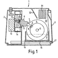
- einen erfindungsgemäßen Antrieb am Beispiel eines Duftverdunsters;
- Figuren 2 und 3
- einen schematischen Querschnitt durch ein erfindungsgemäßes Antriebssystem in verschiedenen Hebelpositionen;
- Fig. 4
- einen schematischen vertikalen Querschnitt durch einen Teil der Antriebsvorrichtung und
- Fig. 5
- eine schematische Darstellung eines Duftverdunsters mit zwei Plattenstapel und doppeltem Antrieb.
- Fig. 1
- a drive according to the invention using the example of a fragrance evaporator;
- Figures 2 and 3
- a schematic cross section through an inventive drive system in different lever positions;
- Fig. 4
- a schematic vertical cross section through part of the drive device and
- Fig. 5
- is a schematic representation of a fragrance evaporator with two plate stacks and double drive.
Duftverdunster 1 gemäß Fig. 1 weist ein Gehäuse 2 mit
Öffnungsklappe 3 auf. Im Inneren des Gehäuses 2 ist ein
Plattenstapel 4 aus lamellenförmig hintereinander
angeordneten kreisförmigen Scheiben, dargestellt. In der
gezeigten Darstellung ist hierbei nur die vorderste Platte
sichtbar. Mit der Achse 5 des Plattenstapels 4 ist eine
Zahnscheibe oder Zahnrad 6 fest verbunden. In das Zahnrad 6
greift ein Hebel 7 mit seiner Hebelspitze 8 ein. Das hintere
Ende des Hebels 7 ist in einem Getriebegehäuse 9 verborgen.
Das Getriebegehäuse 9 wird von einer Getriebeantriebswelle 10
durchsetzt, die über eine elastische Kupplung 11 mit einer
Motorantriebswelle 12 eines Elektromotors 13 verbunden ist.
Auf der Motorantriebswelle 12 ist ein Flügelrad 14 als
Ventilator aufgesetzt.1 has a housing 2
Opening flap 3 open. Inside the housing 2 is a
Der Plattenstapel 4 ist mit seiner Achse 5 in den nicht
dargestellten Stirnseiten einer Duftstoffwanne 15 drehbar
gelagert. Die Duftstoffwanne 15 steht in einer verschiebbaren
Schubladenhalterung 16, an der, wie nicht näher dargestellt,
auch die Öffnungsklappe 3 an ihrer Drehachse 17 schwenkbar
befestigt ist.The
Die Figuren 2 und 3 zeigen einen erfindungsgemäßen
Hebelantrieb in vergrößerter Darstellung. Ein vorderer Hebel
7 ist hierbei mit durchgezogenen Linien dargestellt, während
ein zweiter hinter dem Hebel 7 befindlicher Hebel 7' mit
punktierten Linien gekennzeichnet ist.Figures 2 and 3 show an inventive
Lever drive in an enlarged view. A
Ein Schneckenrad 21, das eine Schnecke 22 kämmt, ist mit
gestrichelten Linien gezeichnet. Das Schneckenrad 21 ist
drehfest mit einer in den Figuren 2 und 3 nicht näher
dargestellten, jedoch in Fig. 4 erkennbaren
Exzenterantriebswelle 23 drehfest verbunden oder in diese
eingearbeitet. Auf der Exzenterantriebswelle 23 sitzen zwei
als Ringschultern ausgebildete Exzenter 24, 24', deren
Mittelachsen R, R' gegenüber der Mittelachse M der
Exzenterantriebswelle 23 versetzt sind, so daß sich eine
Exzentrizität ergibt. Die Exzenter 24, 24' durchsetzen zwei
entsprechende Bohrungen in dem jeweiligen Hebel 7, 7'. Jeder
Hebel 7 bzw. 7' ist jeweils mit einer oberen 25 und unteren
26 Gleitfläche versehen. Diese liegen auf oberen 27 und
unteren 28 Führungsflächen auf, die in das Getriebegehäuse 9
eingearbeitet sind.A
Fig. 4 zeigt die drehfest mit der Getriebeantriebswelle 10
verbundene oder in diese eingearbeitete Schnecke 22. Die
elastische Kupplung 11 ist über eine Steckhülse 29 des
Flügelrads 14 mit der Motorantriebswelle 12 verbunden.
Außerdem ist hier die lamellenartige Anordnung der einzelnen
Scheiben 4' des Plattenstapels 4 ersichtlich.4 shows the rotationally fixed with the
Im Betrieb des Duftverdunsters 1 befindet sich in der
Duftstoffwanne 15, wie mit der Linie F als Flüssigkeitspegel
dargestellt ist, ein flüssiger Duftstoff. Innerhalb des
Duftstoffes liegt teilweise ein Plattenstapel 4. Dieser ist
über seine Achse 5 drehbar in der Duftstoffwanne 15 gelagert.
Er wird über die Hebel 7, 7' und das Zahnrad 6 in eine
Drehbewegung versetzt. Hierbei kommt die mit Duftstoff
benetzte Oberfläche des Plattenstapels 4 mit der Luft im
Verdunstungsraum 30 in Berührung, so daß der Duftstoff von
der Oberfläche in die Luft des Verdunstungsraums 30
verdunstet.In operation of the
Durch das Flügelrad 14 wird über eine nicht näher
dargestellte Öffnung im Gehäuse 2 des Duftverdunsters 1 Luft
angesaugt und über den Plattenstapel 4 geblasen. Hierdurch
kommt es zu einer verstärkten Verdunstung von Duftstoff. Die
mit Duftstoff angereicherte Luft im Verdunstungsraum 30
entweicht anschließend durch entsprechende Lüftungsöffnungen,
wie sie durch die Lüftungsschlitze 31 schematisch angedeutet
sind. Eine Blende 32 lenkt hierbei den Luftstrom zusätzlich
in Richtung auf den Plattenstapel ab.By the
Falls der Duftstoff gewechselt werden soll, so kann die
Klappe 3, wie in Fig. 2 dargestellt, nach unten
heruntergeklappt werden und die Duftstoffwanne 15 auf der
Schubladenhalterung 16 herausgezogen werden. Der
Plattenstapel 4 bleibt hierbei in der Duftstoffwanne 15
gelagert. Anschließend kann die Wechselkassette 18, die die
Duftstoffwanne 15 mitsamt ihres Plattenstapels 4 umfaßt, aus
der Schubladenhalterung 16 entnommen werden und mit einer
Kassettenhaube 19 verschlossen werden. Diese Wechselkassette
18 ist somit bereit für eine längere Lagerung oder für einen
Transport. Eine andere baugleiche Wechselkassette oder auch
dieselbe Wechselkassette kann anschließend wieder in den
Duftverdunster 1 in umgekehrter Reihenfolge eingesetzt
werden.If the fragrance is to be changed, the
Flap 3, as shown in Fig. 2, down
be folded down and the
Der Antrieb für den Plattenstapel 4 geschieht über das
Zahnrad 6 und die Hebel 7, 7'. Die Hebel 7, 7' werden mit
Hilfe des Elektromotors 13, der auch das Flügelrad 14 treibt,
angetrieben. Dies geschieht über die Steckhülse 29 des
Flügelrads 14 und die elastische Kupplung 11, wodurch die
Getriebeantriebswelle 10 angetrieben wird.The drive for the
Hierdurch dreht sich die Schnecke 22 und somit auch die
Exzenterantriebswelle 23 in Richtung des Pfeils P1. Die
Exzenter 24 vollführen dabei eine kreisförmige Bewegung.
Durch diese kreisförmige Bewegung werden die Hebel 7, 7'
sowohl in eine Kippbewegung um den Drehpunkt D, D' als auch
in eine Translationsbewegung in Richtung des Doppelpfeils T
versetzt. Während dieser Bewegungen wird jeder Hebel durch
die obere und untere Führungsfläche 26, 28 geführt, auf denen
er mit seinen oberen bzw. unteren Gleitflächen 25, 26
aufliegt. Durch die besondere Formgebung der Führungsflächen
27, 28 sowie der Gleitflächen 25, 26 in Verbindung mit der
Auslenkung der Mittelachsen R, R' der Exzenter 24, 24' von
der Mittelachse M der Drehachse 23 ist nahezu jede beliebige
Bahnkurve der Hebelspitzen 8, 8' möglich. Von großem Vorteil
ist hierbei eine elliptische Bahnkurve, so daß die
Hebelspitzen 8, 8' in der Vorwärtsbewegung, d. h. in der
vorliegenden Darstellung in der Bewegung nach unten, sich in
Eingriff mit dem Zahnrad 6 befinden. Bei der
Rückwärtsbewegung, d. h. vorliegend bei der Bewegung nach
oben, befinden sich die Hebelspitzen 8, 8' sodann außer
Eingriff mit dem Zahnrad 6 und berühren dessen Zähne nicht.As a result, the
Die Darstellungen der Figuren 2 + 3 zeigen die Hebel 7, 7' in
verschiedenen Stellungen während des Antriebsvorgangs, bei
dem der Plattenstapel 4 in Richtung des Pfeils P2 gedreht
wird. Da die Auslenkung der Exzenter 24, 24' gegenüber der
Mittelachse M der Exzenterantriebswelle 23 um 180° zueinander
versetzt liegt, d. h. die Mittelachsen R, R' der Exzenter 24,
24' und die Mittelachse M der Exzenterantriebswelle 23 liegen
auf einer Geraden, vollzieht sich die Bewegung des Hebels 7'
um einen halben Bewegungszyklus versetzt zur Bewegung des
Hebels 7. Hierdurch befindet sich jeweils mindestens eine
Hebelspitze 8 in Eingriff des Zahnrads 6, so daß dieses nicht
nur in Richtung P2 mitgenommen, sondern auch in jeder
Stellung des Antriebs gegenüber anderen Bewegungen,
beispielsweise einem Zurückdrehen entgegen dem Drehsinn von
P2 verriegelt ist.The representations of FIGS. 2 + 3 show the
Die Hebelspitzen 8, 8' sind nach unten abwärts gerichtet, so
daß Flüssigkeit, die durch das Eintauchen des Zahnrads 6 in
den Duftstoff innerhalb der Duftstoffwanne 15 eventuell zu
den Hebelspitzen 8, 8' gefördert wird, wieder hinunter auf
das Zahnrad 6 abläuft. Die einzigen Stellen, die also somit
mit Duftstoff in Verbindung kommen können, sind lediglich die
Spitzen der Hebel 7, 7'. Es besteht somit keine Gefahr, daß
die restlichen Komponenten des Antriebs in irgendeiner Phase
des Betriebs des Duftverdunsters mit flüssigem Duftstoff in
Berührung kommen.The
Der dargestellte Antrieb für den Plattenstapel 4 läßt sich
auch außerhalb eines erfindungsgemäßen Duftverdunsters
einsetzen. Das dargestellte System läßt sich ohne weiteres,
auch in der nachfolgend beschriebenen Ausführung gern. Fig. 5,
auf jeden rotierenden Gegenstand anwenden, bei dem ein
erfindungsgemäßes Antriebssystem Vorteile bietet. Dies kann
insbesondere bei chemischen Produktionsanlagen der Fall sein,
wo ebenfalls häufig Walzen, Wellen oder dergleichen innerhalb
eines Flüssigkeitsbades drehen müssen, und somit ebenfalls
das Problem auftritt, daß der Antrieb nicht mit der ggf.
aggressiven Flüssigkeit nicht oder nur punktuell in Berührung
kommen darf.The drive shown for the
In Fig. 5 ist eine weitere Ausführungsform eines
erfindungsgemäßen Antriebs dargestellt. Hierbei stehen zwei
Plattenstapel 4, 4' mit jeweils einem Zahnrad 6, 6' parallel
zueinander. Sie werden über einen doppelten Hebelantrieb 33,
33' angetrieben. Die Hebelantriebe 33 entsprechen den
bisherigen oben beschriebenen einfachen Hebelantrieben. Sie
werden über eine gemeinsame Schnecke 22 und die beiden
Schneckenräder 21, 21' angetrieben. Im vorliegenden Fall ist
die Achse der Schnecke 22 und damit auch der
Getriebeantriebswelle 10 senkrecht angeordnet, wobei die
beiden Hebelantriebe 33, 33' unter einem Winkel α bzw. α'
schräg zur senkrechten Achse der Getriebeantriebswelle
stehen. Entsprechend ist auch das Flügelrad 14 sowie der
Elektromotor mit senkrecht verlaufender Achse angeordnet.5 is another embodiment of a
Drive shown according to the invention. Here are two
Durch die Verwendung zweier paralleler Plattenstapel wird die benetzte Oberfläche insgesamt vergrößert, wobei nach wie vor nur ein Antriebsmotor und ein Ventilator notwendig ist. Durch die genannte räumliche Anordnung der Plattenstapel ist eine kompakte Bauweise bei hoher Effizienz eines Duftverdunsters möglich.
- 1
- Duftverdunster
- 2
- Gehäuse
- 3
- Öffnungsklappe
- 4
- Plattenstapel
- 5
- Achse
- 6
- Zahnrad
- 7
- Hebel
- 8
- Hebelspitze
- 9
- Getriebegehäuse
- 10
- Getriebeantriebswelle
- 11
- elastische Kupplung
- 12
- Motorantriebswelle
- 13
- Elektromotor
- 14
- Flügelrad
- 15
- Duftstoffwanne
- 16
- Schubladenhalterung
- 17
- Drehachse
- 21
- Schneckenrad
- 22
- Schnecke
- 23
- Exzenterantriebswelle
- 24
- Exzenter
- 25
- obere Gleitfläche
- 26
- untere Gleitfläche
- 27
- obere Führungsfläche
- 28
- untere Führungsfläche
- 29
- Steckhülse
- 30
- Verdunstungsraum
- 31
- Lüftungsschlitze
- 32
- Blende
- 33
- Hebelantrieb
- 1
- Fragrance evaporator
- 2nd
- casing
- 3rd
- Opening flap
- 4th
- Plate stack
- 5
- axis
- 6
- gear
- 7
- lever
- 8th
- Lever tip
- 9
- Gear housing
- 10th
- Gearbox input shaft
- 11
- elastic coupling
- 12th
- Motor drive shaft
- 13
- Electric motor
- 14
- Impeller
- 15
- Perfume tray
- 16
- Drawer holder
- 17th
- Axis of rotation
- 21
- Worm wheel
- 22
- slug
- 23
- Eccentric drive shaft
- 24th
- eccentric
- 25th
- upper sliding surface
- 26
- lower sliding surface
- 27
- upper guide surface
- 28
- lower guide surface
- 29
- Receptacle
- 30th
- Evaporation space
- 31
- Ventilation slots
- 32
- cover
- 33
- Lever drive
Claims (8)
Applications Claiming Priority (7)
| Application Number | Priority Date | Filing Date | Title |
|---|---|---|---|
| DE4437019 | 1994-10-17 | ||
| DE4437019 | 1994-10-17 | ||
| DE4439555 | 1994-11-05 | ||
| DE4439555 | 1994-11-05 | ||
| DE4441105 | 1994-11-18 | ||
| DE4441105A DE4441105A1 (en) | 1994-10-17 | 1994-11-18 | Fragrance evaporator, especially for toilets |
| EP95936493A EP0783656B1 (en) | 1994-10-17 | 1995-10-14 | Fragrance evaporator, in particular for toilets |
Related Parent Applications (2)
| Application Number | Title | Priority Date | Filing Date |
|---|---|---|---|
| EP95936493A Division EP0783656B1 (en) | 1994-10-17 | 1995-10-14 | Fragrance evaporator, in particular for toilets |
| EP95936493.6 Division | 1995-10-14 |
Publications (3)
| Publication Number | Publication Date |
|---|---|
| EP0838610A2 true EP0838610A2 (en) | 1998-04-29 |
| EP0838610A3 EP0838610A3 (en) | 1998-06-10 |
| EP0838610B1 EP0838610B1 (en) | 2001-07-25 |
Family
ID=25941113
Family Applications (1)
| Application Number | Title | Priority Date | Filing Date |
|---|---|---|---|
| EP97121512A Expired - Lifetime EP0838610B1 (en) | 1994-10-17 | 1995-10-14 | Drive for rotating device like a roll, shaft or similar |
Country Status (3)
| Country | Link |
|---|---|
| EP (1) | EP0838610B1 (en) |
| KR (1) | KR100392171B1 (en) |
| DE (1) | DE4441105A1 (en) |
Cited By (1)
| Publication number | Priority date | Publication date | Assignee | Title |
|---|---|---|---|---|
| WO2000039485A1 (en) | 1998-12-29 | 2000-07-06 | Venta Airwasher Llc. | Drive mechanism for a rotating object such as a roller, shaft, disk or such like |
Families Citing this family (1)
| Publication number | Priority date | Publication date | Assignee | Title |
|---|---|---|---|---|
| DE10354031B4 (en) * | 2003-11-19 | 2005-12-01 | Micro Mechatronic Technologies Ag | Device for introducing very small amounts of liquid into a gas stream |
Citations (7)
| Publication number | Priority date | Publication date | Assignee | Title |
|---|---|---|---|---|
| FR1191751A (en) * | 1958-02-20 | 1959-10-21 | Cie Constr Gros Mat Electromec | Speed reducer |
| US3465605A (en) * | 1967-11-15 | 1969-09-09 | Burroughs Corp | Pawl and ratchet mechanism |
| DE2424140A1 (en) * | 1974-05-17 | 1975-08-28 | ||
| US4261930A (en) * | 1976-06-14 | 1981-04-14 | Byco Sales, Ltd. | Evaporative cooling system |
| US4536626A (en) * | 1984-06-01 | 1985-08-20 | The Singer Company | Timer drive mechanism |
| DE3412745C1 (en) * | 1984-04-05 | 1985-08-22 | Biocomfort Produkte zur Gesundheitspflege GmbH, 7300 Esslingen | Device for cleaning and/or humidifying air |
| FR2595839A1 (en) * | 1986-03-13 | 1987-09-18 | Ako Werke Gmbh & Co | Device for driving a programme mechanism |
Family Cites Families (10)
| Publication number | Priority date | Publication date | Assignee | Title |
|---|---|---|---|---|
| DE7215456U (en) * | 1973-07-19 | Von Wolff R Herstellung Und Vertrieb Elektrotechnischer | Electronic speed controller with follow-up control for ventilation by means of variable-speed fans | |
| US2190972A (en) * | 1938-12-05 | 1940-02-20 | Wagner Electric Corp | Ratio changing lever mechanism |
| US2539059A (en) * | 1945-11-05 | 1951-01-23 | Cohn Harold Jack | Combination dispenser and deodorizer |
| DE2338744A1 (en) * | 1973-07-31 | 1975-02-13 | Hans Seiss | Recirculating filter for cleaning room air - has viscous elements dipping into container and projecting into air stream |
| DE2804100A1 (en) * | 1977-02-08 | 1978-08-10 | Fojon Fernando Gallego | ELECTRONIC ATOMIZING DEVICE THROUGH AEROSOL WITH ADJUSTABLE INTERRUPTED EFFECT |
| DE7904003U1 (en) * | 1979-02-14 | 1979-06-28 | Ohlmann, Hans Armin, Dipl.-Ing., 7987 Weingarten | AIR CLEANING DEVICE |
| DE7913695U1 (en) * | 1979-05-11 | 1979-08-23 | Globol-Werk Gmbh, 8858 Neuburg | HOUSING FOR ACCOMPANYING MASS EVAPORATING IN THE AIR |
| DE3105379A1 (en) * | 1981-02-14 | 1982-09-02 | Agfa-Gevaert Ag, 5090 Leverkusen | Reduction gear for a step-by-step system, preferably for motion picture cameras |
| DE4011514C1 (en) * | 1990-04-10 | 1991-12-19 | Kempski, Diotima Von, 4000 Duesseldorf, De | |
| ES2223692T3 (en) * | 2000-09-15 | 2005-03-01 | Haldor Topsoe A/S | PROCEDURE FOR SILICON CATALYTIC HYDRO TREATMENT CONTAINING NAFTA. |
-
1994
- 1994-11-18 DE DE4441105A patent/DE4441105A1/en not_active Withdrawn
-
1995
- 1995-10-14 KR KR1019970702513A patent/KR100392171B1/en not_active IP Right Cessation
- 1995-10-14 EP EP97121512A patent/EP0838610B1/en not_active Expired - Lifetime
Patent Citations (7)
| Publication number | Priority date | Publication date | Assignee | Title |
|---|---|---|---|---|
| FR1191751A (en) * | 1958-02-20 | 1959-10-21 | Cie Constr Gros Mat Electromec | Speed reducer |
| US3465605A (en) * | 1967-11-15 | 1969-09-09 | Burroughs Corp | Pawl and ratchet mechanism |
| DE2424140A1 (en) * | 1974-05-17 | 1975-08-28 | ||
| US4261930A (en) * | 1976-06-14 | 1981-04-14 | Byco Sales, Ltd. | Evaporative cooling system |
| DE3412745C1 (en) * | 1984-04-05 | 1985-08-22 | Biocomfort Produkte zur Gesundheitspflege GmbH, 7300 Esslingen | Device for cleaning and/or humidifying air |
| US4536626A (en) * | 1984-06-01 | 1985-08-20 | The Singer Company | Timer drive mechanism |
| FR2595839A1 (en) * | 1986-03-13 | 1987-09-18 | Ako Werke Gmbh & Co | Device for driving a programme mechanism |
Cited By (2)
| Publication number | Priority date | Publication date | Assignee | Title |
|---|---|---|---|---|
| WO2000039485A1 (en) | 1998-12-29 | 2000-07-06 | Venta Airwasher Llc. | Drive mechanism for a rotating object such as a roller, shaft, disk or such like |
| US6318203B1 (en) | 1998-12-29 | 2001-11-20 | Venta Airwasher Llc. | Drive for rotating object such as a roller, shaft, plate or the like |
Also Published As
| Publication number | Publication date |
|---|---|
| KR970707419A (en) | 1997-12-01 |
| EP0838610A3 (en) | 1998-06-10 |
| KR100392171B1 (en) | 2003-09-19 |
| EP0838610B1 (en) | 2001-07-25 |
| DE4441105A1 (en) | 1996-04-18 |
Similar Documents
| Publication | Publication Date | Title |
|---|---|---|
| EP0783656B1 (en) | Fragrance evaporator, in particular for toilets | |
| DE2320916C2 (en) | Tank washing machine | |
| DE69912646T2 (en) | ADJUSTABLE RAIL FOR CONVEYING PRODUCTS | |
| EP1836292B1 (en) | Automatic storing device and climatic chamber for laboratory equipment | |
| EP0329092A1 (en) | Mixer-kneader with plural shafts | |
| DE102016002585B3 (en) | Device for treating material | |
| DE19811421A1 (en) | Tank cleaning device for tanks with narrow openings | |
| WO2016096153A1 (en) | Transmission | |
| DE3626517A1 (en) | DRIVE DEVICE FOR AEROSOLS | |
| EP0469376A1 (en) | Machine having two rollers, in particular roller press | |
| DE102011052180B4 (en) | Microtome with reversal of direction | |
| EP0838610B1 (en) | Drive for rotating device like a roll, shaft or similar | |
| DE202004002601U1 (en) | Device for dosing bulk goods with an agitator and a drive unit | |
| EP3124298B1 (en) | Ventilation device | |
| EP3786709A1 (en) | Channel camera | |
| DE2048717C3 (en) | Windshield wiper systems for vehicles, in particular motor vehicles | |
| EP1141583B1 (en) | Drive mechanism for a rotating object such as a roller, shaft, disk or such like | |
| AT392833B (en) | DEVICE FOR CLEANING AND / OR HUMIDIFYING AIR | |
| EP3585946B1 (en) | Floor cleaning machine | |
| EP1976420B1 (en) | Sweeping machine with removable rotary brush | |
| DE4104439A1 (en) | Drive system for cutting rollers of document shredder - drives two rollers by electric motor via worm gear with rollers connected to U=shaped steel plate | |
| DE102015112572B3 (en) | aerator | |
| DE2939451C2 (en) | Machine for cutting corrugated cardboard | |
| EP3827952B1 (en) | Wall saw with guide for saw blade guard | |
| DE19631931A1 (en) | Feed mechanism for goods in self service unit |
Legal Events
| Date | Code | Title | Description |
|---|---|---|---|
| PUAI | Public reference made under article 153(3) epc to a published international application that has entered the european phase |
Free format text: ORIGINAL CODE: 0009012 |
|
| PUAL | Search report despatched |
Free format text: ORIGINAL CODE: 0009013 |
|
| AC | Divisional application: reference to earlier application |
Ref document number: 783656 Country of ref document: EP |
|
| AK | Designated contracting states |
Kind code of ref document: A2 Designated state(s): AT CH DE ES FR GB IT LI NL |
|
| AK | Designated contracting states |
Kind code of ref document: A3 Designated state(s): AT CH DE ES FR GB IT LI NL |
|
| 17P | Request for examination filed |
Effective date: 19980616 |
|
| 17Q | First examination report despatched |
Effective date: 19990914 |
|
| GRAG | Despatch of communication of intention to grant |
Free format text: ORIGINAL CODE: EPIDOS AGRA |
|
| GRAG | Despatch of communication of intention to grant |
Free format text: ORIGINAL CODE: EPIDOS AGRA |
|
| GRAH | Despatch of communication of intention to grant a patent |
Free format text: ORIGINAL CODE: EPIDOS IGRA |
|
| GRAH | Despatch of communication of intention to grant a patent |
Free format text: ORIGINAL CODE: EPIDOS IGRA |
|
| GRAA | (expected) grant |
Free format text: ORIGINAL CODE: 0009210 |
|
| AC | Divisional application: reference to earlier application |
Ref document number: 783656 Country of ref document: EP |
|
| AK | Designated contracting states |
Kind code of ref document: B1 Designated state(s): AT CH DE ES FR GB IT LI NL |
|
| PG25 | Lapsed in a contracting state [announced via postgrant information from national office to epo] |
Ref country code: NL Free format text: LAPSE BECAUSE OF FAILURE TO SUBMIT A TRANSLATION OF THE DESCRIPTION OR TO PAY THE FEE WITHIN THE PRESCRIBED TIME-LIMIT Effective date: 20010725 Ref country code: IT Free format text: LAPSE BECAUSE OF FAILURE TO SUBMIT A TRANSLATION OF THE DESCRIPTION OR TO PAY THE FEE WITHIN THE PRESCRIBED TIME-LIMIT;WARNING: LAPSES OF ITALIAN PATENTS WITH EFFECTIVE DATE BEFORE 2007 MAY HAVE OCCURRED AT ANY TIME BEFORE 2007. THE CORRECT EFFECTIVE DATE MAY BE DIFFERENT FROM THE ONE RECORDED. Effective date: 20010725 Ref country code: GB Free format text: LAPSE BECAUSE OF FAILURE TO SUBMIT A TRANSLATION OF THE DESCRIPTION OR TO PAY THE FEE WITHIN THE PRESCRIBED TIME-LIMIT Effective date: 20010725 Ref country code: FR Free format text: LAPSE BECAUSE OF FAILURE TO SUBMIT A TRANSLATION OF THE DESCRIPTION OR TO PAY THE FEE WITHIN THE PRESCRIBED TIME-LIMIT Effective date: 20010725 |
|
| REF | Corresponds to: |
Ref document number: 203587 Country of ref document: AT Date of ref document: 20010815 Kind code of ref document: T |
|
| REG | Reference to a national code |
Ref country code: CH Ref legal event code: EP |
|
| REF | Corresponds to: |
Ref document number: 59509454 Country of ref document: DE Date of ref document: 20010830 |
|
| REG | Reference to a national code |
Ref country code: CH Ref legal event code: NV Representative=s name: KELLER & PARTNER PATENTANWAELTE AG |
|
| EN | Fr: translation not filed | ||
| NLV1 | Nl: lapsed or annulled due to failure to fulfill the requirements of art. 29p and 29m of the patents act | ||
| GBV | Gb: ep patent (uk) treated as always having been void in accordance with gb section 77(7)/1977 [no translation filed] |
Effective date: 20010725 |
|
| PG25 | Lapsed in a contracting state [announced via postgrant information from national office to epo] |
Ref country code: ES Free format text: LAPSE BECAUSE OF FAILURE TO SUBMIT A TRANSLATION OF THE DESCRIPTION OR TO PAY THE FEE WITHIN THE PRESCRIBED TIME-LIMIT Effective date: 20020131 |
|
| PLBE | No opposition filed within time limit |
Free format text: ORIGINAL CODE: 0009261 |
|
| STAA | Information on the status of an ep patent application or granted ep patent |
Free format text: STATUS: NO OPPOSITION FILED WITHIN TIME LIMIT |
|
| 26N | No opposition filed | ||
| PGFP | Annual fee paid to national office [announced via postgrant information from national office to epo] |
Ref country code: CH Payment date: 20141021 Year of fee payment: 20 Ref country code: DE Payment date: 20141114 Year of fee payment: 20 |
|
| PGFP | Annual fee paid to national office [announced via postgrant information from national office to epo] |
Ref country code: AT Payment date: 20141014 Year of fee payment: 20 |
|
| REG | Reference to a national code |
Ref country code: CH Ref legal event code: PCAR Free format text: NEW ADDRESS: EIGERSTRASSE 2 POSTFACH, 3000 BERN 14 (CH) |
|
| REG | Reference to a national code |
Ref country code: DE Ref legal event code: R071 Ref document number: 59509454 Country of ref document: DE |
|
| REG | Reference to a national code |
Ref country code: CH Ref legal event code: PL |
|
| REG | Reference to a national code |
Ref country code: AT Ref legal event code: MK07 Ref document number: 203587 Country of ref document: AT Kind code of ref document: T Effective date: 20151014 |