BACKGROUND OF THE INVENTION
Electrical devices comprising conductive
polymeric compositions that exhibit a positive
temperature coefficient (PTC) effect are well known
in electronic industries and have many applications,
including their use as constant temperature heaters,
thermal sensors, overcurrent regulators and low-power
circuit protectors. A typical conductive
polymeric PTC composition comprises a matrix of a
crystalline or semi-crystalline thermoplastic resin
(e.g., polyethylene) or an amorphous thermoset resin
(e.g., epoxy resin) containing a dispersion of a
conductive filler, such as carbon black, graphite
chopped fibers, nickel particles or silver flakes.
Some compositions additionally contain nonconductive
fillers, such as metal oxides, flame
retardants, stabilizers, antioxidants, antiozonants,
crosslinking agents and dispersing agents.
At a low temperature (e.g. room
temperature), the polymeric PTC composition has a
compact structure and resistivity property that
provides low resistance to the passage of an
electrical current. However, when a PTC device
comprising the composition is heated or an
overcurrent causes the device to self-heat to a
transition temperature, a less ordered polymer
structure resulting from a large thermal expansion
presents a high resistivity. In electrical PTC
devices, for example, this high resistivity limits
the load current, leading to circuit shut off. In
the context of this invention, Ts is used to denote
the "switching" temperature at which the "PTC
effect" (a rapid increase in resistivity) takes
place. The sharpness of the resistivity change as
plotted on a resistance versus temperature curve is
denoted as "squareness", i.e the more vertical the
curve at the Ts, the smaller is the temperature
range over which the resistivity changes from the
low to the maximum values. When the device is
cooled to the low temperature value, the resistivity
will theoretically return to its previous value.
However, in practice, the low-temperature
resistivity of the polymeric PTC composition may
progressively increase as the number of low-high-low
temperature cycles increases, an electrical
instability effect known as "ratcheting".
Crosslinking of a conductive polymer by chemicals or
irradiation, or the addition of inorganic fillers or
organic additives are usually employed to improve
electrical stability.
In the preparation of the conductive PTC
polymeric compositions, the processing temperature
often exceeds the melting point of the polymer by
20°C or more, with the result that the polymers may
undergo some decomposition or oxidation during the
forming process. In addition, some devices exhibit
thermal instability at high temperatures and/or high
voltages that may result in aging of the polymer.
Thus, inorganic fillers and/or antioxidants, etc.
may be employed to provide thermal stability.
One of the applications for PTC electrical
devices is a self-resettable fuse to protect
equipment from damage caused by an over-temperature
or over-current surge. Currently available
polymeric PTC devices for this type of application
are based on conductive materials, such as carbon
black filled polyethylene, that have a low Ts, i.e.
usually less than 125°C. However, for some
applications, e.g. circuit protection of components
in the engine compartment or other locations of
automobiles, it is necessary that the PTC
composition be capable of withstanding ambient
temperatures as high as 125°C, without changing
substantially in resistivity. Thus, for these
applications, the use of such a polyethylene-based
or similar device is inappropriate. Recent interest
in polymeric PTC materials, therefore, has focused
on selection of a polymer, copolymer or polymer
blend that has a higher and sharper melting point,
suitable for comprising a high temperature polymeric
PTC composition (i.e. a composition having a Ts
higher than 125°C).
For many circuits, it is also necessary
that the PTC device have a very low resistance in
order to minimize the impact of the device on the
total circuit resistance during normal circuit
operation. As a result, it is desirable for the PTC
composition comprising the device to have a low
resistivity, i.e. 10 ohm-cm (Ωcm) or less, which
allows preparation of relatively small, low
resistance PTC devices. There is also a demand for
protection circuit devices that not only have low
resistance but show a high PTC effect (i.e. at least
3 orders of magnitude in resistivity change at Ts)
resulting in their ability to withstand high power
supply voltages. In comparison with low Ts
materials, some high temperature polymeric PTC
compositions have been shown to exhibit a PTC effect
of up to 104 or more. High temperature polymeric
PTC compositions also generally have more rapid
switching times than low Ts compositions, (i.e. the
time required to reduce the electrical current to 50
percent of its initial value at the Ts), even at low
ambient temperatures. Thus, PTC devices comprising
high temperature polymeric PTC materials are
desirable because they may be expected to have
better performance than low temperature polymeric
PTC devices, and also be less dependent on the
ambient operating temperature of the application.
High temperature polymeric PTC materials
such as homopolymers and copolymers of
poly(tetrafluorethylene), poly(hexafluoropropylene)
and poly(vinylidene fluoride) (PVDF) or their
copolymers and terpolymers with, for example,
ethylene or perfluorinated-butyl ethylene, have been
investigated as substitutes for polyethylene-based
materials to achieve a higher Ts. Some of these
compositions exhibited a Ts as high as 160-300°C and
a resistivity change at Ts of up to four orders of
magnitude (104) or more. However, thermal
instability and the potential for release of
significant amounts of toxic and corrosive hydrogen
fluoride if overheating occurs, has restricted these
materials from practical consideration for high
temperature applications.
A variety of other polymers have been
tested to explore PTC characteristics. These
polymers include polypropylene, polyvinylchloride,
polybutylene, polystyrene, polyamides (such as nylon
6, nylon 8, nylon 6,6, nylon 6,10 and nylon 11),
polyacetal, polycarbonate and thermoplastic
polyesters, such as poly(butylene terephthalate) and
poly(ethylene terephthalate). However, under the
conditions reported, none of these polymers
exhibited a useful high temperature PTC effect with
a low resistivity state of 10 Ωcm or less.
More recently, a novel high temperature
polymeric PTC composition comprising a polymer
matrix of an amorphous thermoplastic resin
(crystallinity less than 15%) and a thermosetting
resin (e.g. epoxy) has been described. Because the
selected thermoplastic resin and thermoset resin
were mutually soluble, the processing temperature
was substantially low and depended on the curing
temperature of the thermoset resin. The use of a
thermoset resin apparently assured sufficient
crosslinking and no further crosslinking was
employed. However, electrical instability
(ratcheting) was still a problem with these
compositions.
For the foregoing reasons, there is a need
for the development of alternative polymeric PTC
compositions, and PTC devices comprising them, that
exhibit a high PTC effect at a high Ts, have a low
initial resistivity, are capable of withstanding
high voltages, and exhibit substantial electrical
and thermal stability.
SUMMARY OF THE INVENTION
The present invention provides a high
temperature PTC device comprising a conductive
polymeric composition that exhibits high temperature
PTC behavior (a Ts that falls between 150°C and
190°C), a high PTC effect (at least 103), and a low
initial resistivity (preferably 10 Ωcm or less at
25°C). In particular, the conductive polymeric
composition of the invention comprises a
semicrystalline polymer component that comprises
nylon-12 or nylon-11, and a particulate conductive
filler. The conductive filler may be selected from
carbon black, graphite, metal particles, and
mixtures of these. Preferably, the composition is
crosslinked by chemical means or irradiation to
enhance electrical stability and may comprise an
inorganic filler and/or an antioxidant to enhance
electrical and/or thermal stability.
That the conductive polymeric composition
of the invention exhibits such favorable PTC
properties is surprising, since it has previously
been suggested that polyamides are useful only in
compositions having a low Ts (about 125°C or less)
and may exhibit a low PTC effect, e.g., less than
101.
The semicrystalline polymer component of
the composition may also comprise a polymer blend
containing, in addition to the first polymer, 1%-20%
by volume of one or more additional semicrystalline
polymers. Preferably, the additional polymer(s)
comprises a polyolefin-based or polyester-based
thermoplastic elastomer, or mixtures of these.
The high temperature PTC device of the
invention comprises the conductive polymeric
composition and at least two electrodes which are in
electrical contact with the composition to allow an
electrical current to pass through the composition
under an applied voltage, which may be as high as 70
volts or more.
BRIEF DESCRIPTION OF THE DRAWINGS
Figure 1 is a schematic illustration of a
PTC chip comprising the polymeric PTC composition of
the invention sandwiched between two metal
electrodes.
Figure 2 is a schematic illustration of an
embodiment of a PTC device according to the
invention, comprising the PTC chip of Figure 1 with
two attached terminals.
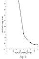
Figure 3 is a graphic illustration of the
resistivity of the PTC compositions of Examples 1-6,
comprising nylon-12 and volume percentages of carbon
black ranging from 20%-40%.
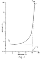
Figure 4 is a graphic illustration of the
PTC behavior of the device comprising the 35 volume
% carbon black composition of Example 4, where Rpeak
is the resistance at the peak of a resistance versus
temperature curve and R25 is the resistance at 25°C.
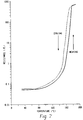
Figure 5 is a graphic illustration of the
switching test results for the PTC device comprising
the uncrosslinked composition of Example 4 plotted
as a resistance versus temperature curve.
Figure 6 is a graphic illustration of the
effects of various doses of gamma irradiation on the
device resistance at 25°C of the composition of
Example 4 (see Examples 10-13) after the indicated
number of cycles, where each cycle represents an
excursion from 25°C to the Ts and back to 25°C.
Figure 7 is a graphic illustration of the
switching test results for the PTC device comprising
the composition of Example 4 after 10 Mrads of gamma
irradiation (see Example 13).
DETAILED DESCRIPTION OF THE INVENTION
The high temperature polymeric PTC device
of the present invention comprises a conductive
polymeric composition that demonstrates PTC behavior
at a Ts greater than 125°C, preferably between 140°C
and 200°C, and more preferably, between 150°C and
190°C. The conductive polymeric composition also
demonstrates a high PTC effect, i.e. the maximum
resistivity, as plotted on a resistivity versus
temperature curve, is preferably greater than 104
times, but is at least 103 times, greater than the
initial resistivity at 25°C. The preferred
polymeric composition exhibits an initial
resistivity of 100 Ωcm or less at 25°C, and more
preferably 10 Ωcm or less, thus providing for a PTC
device having a low resistance of 10 mΩ to 100 mΩ,
preferably 15 mΩ to 75 mΩ, with an appropriate
geometric design and size, as discussed further
below.
The conductive polymeric composition
comprising the high PTC device of the invention
comprises a polymeric component, which may comprise
nylon-12 or nylon-11, or a polymer blend of nylon-12
or nylon-11 with another semicrystalline polymer,
preferably a polyolefin-based or polyester-based
thermoplastic elastomer. The composition further
comprises a particulate conductive filler, as
described further below.
It is known that the Ts of a conductive
polymeric composition is generally slightly-below
the melting point (Tm) of the polymeric matrix.
Therefore, theory predicts that a polymeric PTC
composition may exhibit a high Ts if the melting
point of the polymer is sufficiently high. If the
thermal expansion coefficient of the polymer is also
sufficiently high near the Tm, a high PTC effect may
also occur. Further, it is known that the greater
the crystallinity of the polymer, the smaller the
temperature range over which the rapid rise in
resistivity occurs. Thus, crystalline polymers
exhibit more "squareness", or electrical stability,
in a resistivity versus temperature curve.
The preferred semicrystalline polymer
component in the conductive polymeric composition of
the present invention has a crystallinity in the
range of 20%-70%, and preferably 25%-60%. In order
to achieve a composition with a high Ts and a high
PTC effect, it is preferable that the
semicrystalline polymer has a melting point (Tm) in
the temperature range of 150°C to 200°C, preferably
160°-195°C, and a high thermal expansion coefficient
value at a temperature in the range Tm to Tm minus
10°C that is at least three times greater than the
thermal expansion coefficient value at 25°C.
Preferably, the polymer substantially withstands
decomposition at a processing temperature that is at
least 20°C and preferably less than 40°C above the
Tm.
A suitable first polymer for use in the
invention comprises nylon-12 obtained from Elf
Atochem North America, Inc., Philadelphia, PA, or
EMS American Grilon, Inc., Sumter, SC, with the
commercial names of Aesno-TL and Grilamid L20G,
respectively. A nylon-11 polymer suitable for use
in the invention may be obtained from Elf Atochem
North America, Inc., with the commercial name of
Besno-TL. Each of the nylon polymers has a
crystallinity of 25% or greater and a Tm of 170°C or
greater. The thermal expansion coefficient (γ) of
each of these polymers at 25°C and within a range of
Tm to Tm minus 10°C is given in Table 1.
The semicrystalline polymer component of
the composition may also comprise a polymer blend
containing, in addition to the first polymer, 1%-20%
by volume of a second semicrystalline polymer.
Preferably, the second semicrystalline polymer
comprises a polyolefin-based or polyester-based
thermoplastic elastomer. The thermoplastic
elastomer preferably has a Tm in the range of 150°C
to 190°C and a thermal expansion coefficient value
at a temperature in the range Tm to Tm minus 10°C
that is at least five times greater than the thermal
expansion coefficient value at 25°C. Suitable
thermoplastic elastomers for forming a polymer blend
with nylon-12 or nylon-11 are polyolefin-based or
polyester-based and obtained from Advanced Elastomer
Systems, Akron, OH and DuPont Engineering Polymers,
Wilmington, DE, with the commercial names of
Santoprene and Hytrel G-4074, respectively. The
thermal expansion coefficients of each of these
elastomers at 25°C and within the range Tm to Tm
minus 10°C are listed in Table 1.
In the conductive polymeric composition,
the particulate conductive filler may comprise
carbon black, graphite, metal particles, or a
combination of these. Metal particles may include,
but are not limited to, nickel particles, silver
flakes, or particles of tungsten, molybdenum, gold
platinum, iron, aluminum, copper, tantalum, zinc,
cobalt, chromium, lead, titanium, or tin alloys.
Such metal fillers for use in conductive polymeric
compositions are known in the art.
| POLYMER | Aesno-TL (Nylon-12) | Grilamid L20G (Nylon-12) | Santoprene [TPE(polyolefin-based] | Hytrel-G4074 [TPE(polyester-based] |
| γ at 25°C (cm/cm°C) | 1.1x10⁻⁴ | 1.2x10⁻⁴ | 2.8x10⁻⁴ | 1.8x10⁻⁴ |
| γ near Tm (cm/cm°C) | 5.5x10⁻⁴ | 4.9x10⁻⁴ | 29.2x10⁻⁴ | 30.9x10⁻⁴ |
Preferably, the conductive particles
comprise a highly conductive carbon black, such as
Sterling SO N550, Vulcan XC-72, and Black Pearl 700
(all available from Cabot Corporation, Norcross,
GA), all known in the art for their use in
conductive polymeric compositions. A suitable
carbon black, such as Sterling SO N550, has a
particle size of about 0.05-0.08 microns, and a
typical particle aggregate sphere size of 0.25-0.5
microns as determined by DiButyl Phthalate (DBP)
absorption. The volume ratio of the particulate
conductive filler to the polymer component ranges
from 10:90 to 60:40, preferably 20:80 to 50:50, and
more preferably 30:70 to 40:60.
In addition to the semicrystalline polymer
component and the particulate conductive filler, the
conductive polymeric composition may additionally
comprise additives to enhance electrical and thermal
stability. Suitable inorganic additives include
metal oxides, such as magnesium oxide, zinc oxide,
aluminum oxide, titanium oxide, or other materials,
such as calcium carbonate, magnesium carbonate,
alumina trihydrate, and magnesium hydroxide. Such
inorganic additives may be present in the
composition in an amount by weight of 1% to 10%, and
more preferably from 2% to 8%. Organic
antioxidants, preferably those having a melting
point below the temperature at which the conductive
polymeric composition is processed, may optionally
be added to the composition to increase the thermal
stability. Examples of such antioxidants include,
but are not limited to, phenol or aromatic amine
type heat stabilizers, such as N,N'-1,6-hexanediylbis(3,5-bis(1,1-dimethylethyl)-4-hydroxybenzene)
propanamide (Irganox-1098, Ciba-Geigy
Corp., Hawthorne, NY), N-stearoyl-4-aminophenol and
N-lauroyl-4-aminophenol. The proportion by weight
of the organic antioxidant agent in the composition
may range from 0.1% to 5%, preferably from 0.2% to
2%. The conductive polymeric composition may also
comprise inert fillers, antiozonants, fire
retardants, stabilizers, dispersing agents,
crosslinking agents or other components, in various
proportions as known in the art.
To enhance electrical stability, the
conductive polymer composition may be crosslinked by
chemicals, such as organic peroxide compounds, or by
irradiation, such as by high energy electrons,
ultraviolet radiation or by gamma radiation, as
known in the art. Although crosslinking is
dependent on the polymeric components and the
application, normal crosslinking levels are
equivalent to that achieved by an irradiation dose
in the range of 2 to 50 Mrads, preferably 2.5 to 30
Mrads, e.g. 10 Mrads. If crosslinking is by
irradiation, the composition may be crosslinked
before or after attachment of the electrodes.
In an embodiment of the invention, the
high temperature PTC device of the invention
comprises a PTC "chip" 1 illustrated in Figure 1 and
electrical terminals 12 and 14, as described below
and schematically illustrated in Figure 2. As shown
in Figure 1, the PTC chip 1 comprises the conductive
polymeric composition 2 of the invention sandwiched
between metal electrodes 3. The electrodes 3 and
the PTC composition 2 are preferably arranged so
that the current flows through the PTC composition
over an area LxW of the chip 1 that has a thickness,
T, such that W/T is at least 2, preferably at least
5, especially at least 10. The electrical
resistance of the chip or PTC device also depends on
the thickness and the dimensions W, L, and T may be
varied in order to achieve a preferable resistance,
described below. For example, a typical PTC chip
generally has a thickness of 0.05 to 5 millimeters
(mm), preferably 0.1 to 2.0 mm, and more preferably
0.2 to 1.0 mm. The general shape of the chip/device
may be that of the illustrated embodiment or may be
of any shape with dimensions that achieve the
preferred resistance.
It is generally preferred to use two
planar electrodes of the same area which are placed
opposite to each other on either side of a flat PTC
polymeric composition of constant thickness. The
material for the electrodes is not specially
limited, and can be selected from silver, copper,
nickel, aluminum, gold, and the like. The material
can also be selected from combinations of these
metals, e.g. nickel-plated copper, tin-plated
copper, and the like.
An embodiment of the PTC device 10 is
illustrated in Figure 2, with terminals 12 and 14
attached to the PTC chip illustrated in Figure 1.
When an AC or a DC current is passed through the PTC
device, the device preferably demonstrates an
initial resistance at 25°C of 10-100 mΩ, and more
preferably 15-75 mΩ. The ratio of the peak
resistance (Rpeak) of the PTC chip or device to the
resistance of the chip/device at 25°C (R25) is at
least 103, preferably 104 to 105, where Rpeak is the
resistance at the peak of a resistance versus
temperature curve that plots resistance as a
function of temperature, as illustrated in Figure 4.
The Ts is shown as the temperature at the
intersection point of extensions of the
substantially straight portions of a plot of the log
of the resistance of the PTC chip/ device and the
temperature which lies on either side of the portion
showing the sharp change in slope.
The high temperature PTC device of the
invention also demonstrates a resistance R1000 at
25°C that is less than three times, and preferably
less than 2.5 times, a resistance Ro where Ro is the
initial resistance at 25°C and R1000 is the
resistance at 25°C after 1000 temperature excursions
(cycles) to the Ts and back to 25°C. (See, for
example, the data of Table 6). For a single cycle,
the PTC device may also be capable of withstanding a
voltage of up to 70 volts or more without failure.
Preferably, the device withstands a voltage of at
least 20 volts, and more preferably, at least 30
volts without failure.
The conductive polymeric compositions of
the invention are prepared by methods known in the
art. In general, the polymer or polymer blend, the
conductive filler and additives (if appropriate) are
compounded at a processing temperature that is at
least 20°C higher, but less than 40°C higher, than
the melting temperature of the polymer or polymer
blend. After compounding, the homogeneous
composition may be obtained in any form, such as
pellets. The composition is then compression molded
or extruded into a thin sheet, at a temperature
similar to that used during compounding. Metallic
electrodes, in the form of metal foil covering both
the top and bottom of a layer of the polymer, are
applied to the composition during the compression
molding or extrusion process.
The pressure and processing time employed
during compression molding or extrusion are variable
and depend upon the composition. For example, the
higher the filler content (e.g. carbon black), the
higher is the pressure used, and the longer is the
processing time. Compositions, such as those
described below in the Examples, and containing
nylon-12, carbon black, and magnesium oxide in
varying proportions are compression molded at a
pressure of 1 to 10 MPa, preferably 2 to 4 MPa, with
a processing time of 5 to 60 minutes, preferably 10
to 30 minutes. By controlling the parameters of
pressure and time, different sheets of various
thicknesses may be obtained. The sheets are then
cut to obtain PTC chips having predetermined
dimensions and comprising the conductive polymeric
composition sandwiched between the metal electrodes.
The composition may be crosslinked by irradiation,
if desired, prior to cutting of the sheets into PTC
chips. The sheets from which the chips are cut are
preferably of uniform thickness. Electrical
terminals are then soldered to each individual chip
to form PTC electrical devices.
The following examples illustrate
embodiments of the conductive polymeric compositions
and high temperature PTC devices of the invention.
However, these embodiments are not intended to be
limiting, as other methods of preparing the
compositions and devices to achieve desired
electrical and thermal properties may be determined
by those skilled in the art. The compositions, PTC
chips and PTC devices were tested for PTC properties
directly by a resistance versus temperature (R-T)
test and indirectly by a switching test, overvoltage
test and cycle test, as described below. The number
of samples tested from each batch of chips is
indicated below and the results of the testing
reported in the Tables are an average of the values
for the samples.
The resistances of the PTC chips and
devices were measured, using a four-wire standard
method, with a Keithley 580 micro-ohmmeter (Keithley
Instruments, Cleveland, OH) having an accuracy of
±0.01 mΩ. To determine an average resistance value
at 25°C, the resistances of 20 to 30 chips and
devices were measured for each PTC composition. The
resistivity was calculated from the measured
resistance and the geometric area and thickness of
the chip.
To determine the resistance/resistivity
behavior of the PTC devices versus the temperature
(R-T test), three to four device samples were
immersed in an oil bath having a constant heating
rate of about 2°C per minute. The temperature and
the resistance/resistivity of each of the samples
were measured simultaneously. Resistance and
temperature were measured with a multimeter having
an accuracy of ±0.1 mΩ and an RTD digital
thermometer having an accuracy of ±0.01°C,
respectively. The PTC effect was calculated by the
value of Rpeak/R25.
The Ts of the PTC composition comprising
the PTC devices was determined by a constant
voltage switching test, usually conducted by passage
of a DC current through the device at, for example,
10 volts and 10 amperes (amps). Because of the
self-heating caused by the high current, the device
quickly reaches the Ts and, with the voltage
remaining constant, the current suddenly drops to a
low value (OFF Current or trickle current) which can
be used to determine the OFF state resistance of the
device. The devices exhibit the desired PTC effect
if they are capable of staying and stabilizing at
the Ts for at least 150 seconds at the specified
condition (e.g. 10 volts and 10 amps). During this
test, a computer automatically records the initial
voltage, initial current, OFF current, the switching
temperature and the switching time. The devices
that "pass" the initial 10 volt/10 amps test are
then subjected sequentially to switching tests at
higher voltages, e.g. 15 volts/10 amps, 20 volts/10
amps, 30 volts/10 amps, 50 volts/10 amps, etc.,
until the device fails. Failure of the device is
indicated if the device is incapable of stabilizing
at the Ts for 150 seconds or undergoes "thermal
runaway". A sample size of three to four was used
for this test.
The cycle test is performed in a manner
similar to the switching test, except that the
switching parameters (usually 10.5 volts and 15
amps) remain constant during a specified number of
switching cycle excursions from 25°C to the Ts and
back to 25°C. The resistance of the device is
measured at 25°C before and after specified cycles
and the number of total cycles may be up to 1000 or
more. The initial resistance at 25°C is designated
Ro and the resistance after X numbers of cycles is
designated RX, e.g. R1000. The cycle test sample
size was generally five.
The overvoltage test was performed on
eight to ten device samples using a variable voltage
source to test the maximum voltage that the PTC
device can withstand. The maximum withstood voltage
is determined when a knee point ("knee voltage")
appears in a power versus voltage curve.
PREPARATION OF NYLON-12/CARBON BLACK COMPOSITIONS
Examples 1-5
Nylon-12/carbon black compositions
containing various volume percentages of nylon-12
and carbon black are illustrated in Table 2 as
Examples 1-5. The compositions of each of the
Examples were generally prepared according to the
method described below for preparing the 35 volume %
Carbon Black/65 volume % Nylon-12 composition.
Variations from the described method for each
Example are illustrated in the Table. Examples 1-5
contain volume ratios of nylon-12 (Aesno-TL) to
carbon black of 80:20 (20 volume %), 75:25 (25
volume %), 70:30 (30 volume %), 65:35 (35 volume %
or 35 vol%) and 60:40 (40 volume %).
Preparation of the 35 volume % Carbon Black/65
volume % Nylon-12 Composition
To 197 parts by weight of nylon-12 (Aesno-TL)
were added 172 parts by weight of carbon black
(Sterling SO N550) and 13 parts by weight of
magnesium oxide (Aldrich Chemical Co.). The
corresponding volume fraction of nylon-12 to carbon
black is 65/35, calculated by using a value for the
compact density of the carbon black of 1.64 g/cm3
and for the density of the Aesno-TL of 1.01 g/cm3.
After slight mechanical stirring, the crude mixture
was mixed to homogeneity in a Brabender mixer at a
temperature of 202-205°C. The homogeneous mixture
was then cooled and chopped into pellets.
The pelleted nylon-12/carbon black mixture
was covered on both top and bottom layers with
nickel-plated copper foil electrodes and compression
molded at 3 MPa and 205°C for 20 minutes. The
thickness of the resulting molded sheet was
typically about 0.4 mm to 0.5 mm. Chip samples of
2x1.1 cm2 were cut from the sheets. Copper
terminals were then soldered to each of the chip
samples to form PTC devices. The compositions were
not crosslinked.
Composition Evaluations, Examples 1-5
The resistivity at 25°C of the PTC chips
comprising the conductive nylon-12 compositions of
Examples 1-5 was measured and are shown in Table 2
and graphically as a logarithmic plot in Figure 3.
The data show that compositions containing 25% to
40% carbon black by volume (75% to 60% nylon-12 by
volume) exhibit an initial resistivity at 25°C of
less than 100 Ωcm and that compositions containing
30% to 40% carbon black by volume exhibit preferred
initial resistivities of less than 10 Ωcm. The
average resistance of the chips at 25°C was also
measured and chips comprising a composition
containing 35% to 40% carbon black by volume exhibit
preferred initial resistances of between 10 mΩ and
100 mΩ and more preferred resistances of 15 mΩ to 75
mΩ. For example, chips with the 35 volume % carbon
black composition showed a resistance of 28.9 mΩ.
When copper terminals were soldered to these chips
to form PTC devices, the resistance of the devices
at 25°C increased to 50 mΩ to 75 mΩ.
Examples 6-9
The compositions of Examples 6-9
illustrated in Table 3 were prepared according to
the method for Examples 1-5 except that the nylon-12
was Grilamid L20G. Examples 6-9 contain volume
ratios of nylon-12 to carbon black of 70:30 (30
volume %), 67.5:32.5 (32.5 volume %), 65:35 (35
volume %) and 62:38 (38 volume %).
As shown in
Table 3, the average chip
resistivity at 25°C for each of the compositions
comprising Grilamid L20G was comparable to that of
chips comprising the 30 to 40 volume % compositions
of Examples 1-5, and each exhibited a preferred
resistivity value of less than 10 Ωcm. The average
chip resistance of the 30 and 32.5 volume %
compositions, however, was high and could lead to a
device resistance that would fall outside the
preferred 15 mΩ to 75 mΩ range. Therefore, these
compositions were not tested further. When
terminals were attached to chips comprising the 35
and 38 volume % compositions to form PTC devices,
the average resistance of the devices at 25°C fell
within the preferred range. These devices were
capable of withstanding an average of 34 to 47 volts
(knee voltage) during the overvoltage test without
failure and were also capable of sustaining a T
s for
at least 150 seconds under an applied voltage of 25
to 30 volts and a current of 10 amps during the
switching test, showing a high PTC effect.
| Example No. | 1 | 2 | 3 | 4 | 5 |
| Volume % Carbon Black | 20% | 25% | 30% | 35% | 40% |
| Weight % Carbon Black | 28.9 | 35.2 | 41.0 | 46.6 | 52.0 |
| Carbon Black (Sterling N550) | 98.4 | 123.1 | 147.6 | 172.2 | 196.8 |
| Nylon-12 (Aesno-TL) | 242.4 | 226.8 | 212.1 | 197.1 | 181.8 |
| Magnesium Oxide | 12.1 | 12.4 | 12.8 | 13.1 | 13.5 |
| Molding Temperature (°C) | 198 | 200 | 202 | 205 | 210 |
| Molding Pressure (MPa) | 2 | 2 | 2.5 | 3 | 3.5 |
| Molding Time (minutes) | 10 | 10 | 15 | 20 | 20 |
| Resistivity at 25°C (Ωcm) | 4.44x10⁵ | 49.9 | 5.25 | 1.25 | 0.664 |
| Average Chip Resistance at 25°C (mΩ) | 5.25x10⁶ | 738 | 124 | 28.9 | 18.1 |
| Example No. | 6 | 7 | 8 | 9 |
| Volume % Carbon Black | 30% | 32.5% | 35% | 38% |
| Weight % Carbon Black | 41.0 | 43.9 | 46.6 | 49.9 |
| Carbon Black (Sterling N550) | 98.4 | 106.1 | 114.8 | 124.6 |
| Nylon-12 (Grilamid L20G) | 141.4 | 136.4 | 131.3 | 125.2 |
| Magnesium Oxide | 8.51 | 8.63 | 8.75 | 8.87 |
| Molding Temperature (°C) | 200 | 200 | 205 | 205 |
| Molding Pressure (MPa) | 2.5 | 2.5 | 3 | 3 |
| Molding Time (minutes) | 15 | 15 | 20 | 20 |
| Resistivity at 25°C (Ωcm) | 2.78 | 1.66 | 1.07 | 0.796 |
| Average Chip Resistance at 25°C (mΩ) | 65.51 | 37.50 | 19.79 | 17.24 |
| Average Device Resistance at 25°C (mΩ) | ND | ND | 35.46 | 28.54 |
| Average Knee Voltage (volts) | ND | ND | 47 | 34 |
| Maximum Voltage For Switching Test (volts) | ND | ND | 30 | 25 |
| PTC Effect | ND | ND | 1.18x10⁴ | 8.28x10³ |
Chips comprising the 35 volume % carbon
black/65 volume % nylon-12 composition of Example 4
were selected for further testing. The PTC effect
of the uncrosslinked composition was determined
directly by an R-T test (Figures 4 and 5). As
illustrated, the Ts of the composition is 161.3°C and
shows a PTC effect of 1.58x10⁴. The reversibility
of the PTC effect is illustrated, although the level
of the resistance at 25°C does not return to the
initial level. As discussed below in Example 10,
crosslinking of the composition improved this
"ratcheting" effect.
Because of the demonstrated high PTC
effect of the composition of Example 4, a device
comprising the composition can withstand a voltage
of as high as 50 volts and a current of as high as
35 amps during the switching test and the
overvoltage test reported in Tables 4 and 6. The
device demonstrates a low average resistance of 59.3
mΩ at 25°C (Table 6).
The data of
Table 4 illustrate the results
of a switching test performed for the uncrosslinked
35 volume % composition of Example 4 for various
voltages applied at 25°C. Both the T
s and the ratio
of resistances (R
T/R
O) increased with the increase of
voltage applied. This indicates that, because of
the high PTC effect, the material can withstand high
voltage. As the voltage was increased to 50 volts,
the R
T/R
o increased to 4 orders of magnitude with a
stable T
s of 164.5°C. The composition was then
tested for switching properties at various ambient
temperatures, as illustrated in
Table 5. The
results demonstrate acceptable switching properties
under 25 volts and 10 amps at ambient temperatures
ranging from -40°C to 50°C.
| Switching Test Results for the Uncrosslinked 35 vol% Carbon Black/65 vol% Nylon-12 Composition at 25°C |
| Test No. | Voltage Applied | Current (A) | Off Resistance | Ratio of Resistance | Ts |
| | (V) | ON | OFF | (Ω) | (RT/RO) | (°C) |
| 1 | 5 | 5 | 0.85 | 5.88 | 113.1 | 149.5 |
| 2 | 10 | 5 | 0.44 | 22.73 | 437.1 | 158.5 |
| 3 | 12.5 | 10 | 0.35 | 35.71 | 686.8 | 159.2 |
| 4 | 15 | 10 | 0.33 | 45.45 | 874.1 | 159.5 |
| 5 | 17.5 | 10 | 0.27 | 64.81 | 1.248x10³ | 159.8 |
| 6 | 20 | 10 | 0.23 | 86.96 | 1.672x10³ | 160.2 |
| 7 | 30 | 10 | 0.16 | 187.5 | 3.606x10³ | 161.1 |
| 8 | 30 | 20 | 0.14 | 214.3 | 4.121x10³ | 161.3 |
| 9 | 50 | 10 | 0.09 | 555.6 | 1.068x10⁴ | 164.5 |
| 10 | 50 | 20 | 0.09 | 555.6 | 1.068x10⁴ | 165.2 |
| 11 | 50 | 35 | 0.09 | 625.0 | 1.202x10⁴ | 165.5 |
| Switching Properties Versus Testing Temperature for the Uncrosslinked 35 vol% Carbon Black/65 vol% Nylon-12 Composition |
| Test No. | Testing Temperature | Off Current (A) | Off Resistance | Ratio of Resistance | Ts |
| | (°C) | | (Ω) | (RT/RO) | (°C) |
| 1 | -40 | 0.26 | 96.2 | 2.16x10³ | 161.3 |
| 2 | 0 | 0.21 | 119.1 | 2.68x10³ | 163.1 |
| 3 | 15 | 0.20 | 125.0 | 2.81x10³ | 164.8 |
| 4 | 50 | 0.15 | 166.7 | 3.75x10³ | 167.1 |
A composition containing a 35 volume % of
carbon black/65 volume % nylon-12 (Aesno-TL) was
prepared according to the method of Example 4,
except that prior to attachment of the terminals,
the chips were irradiated with various doses of
gamma irradiation from a Cobalt-60 source.
Terminals were then attached to the irradiated chips
and the resulting PTC devices were subjected to a
cycle test comprising 1000 cycles. As illustrated
in Figure 6, an irradiation dose of 2.5, 5, 7.5 or
10 Mrads (Examples 10, 11, 12 and 13, respectively)
improved the resistance stability at 25°C of the
devices after cycling compared to that of devices of
Example 4 that were not irradiated. The reversible
PTC effect of the composition irradiated with 10
Mrads is illustrated in Figure 7.
A comparison of the properties of devices
prepared according to Example 4 (unirradiated) and
Examples 10-13 (irradiated) are reported in Table 6.
It can be seen that after the irradiation, the PTC
effect was slightly decreased, but the electrical
stability was greatly enhanced, as evidenced by the
significantly lowered increase in the electrical
resistance of the device at 25°C after up to 1000
cycles.
Examples 14-16
A composition containing a 35 volume % of
carbon black/65% volume % nylon-12 (Aesno-TL) was
prepared according to the method of Example 4,
except that an antioxidant (Irganox 1098) was added
to the composition during compounding. The data of
Table 7 illustrate that the addition of the
antioxidant did not substantially affect the chip or
device resistance at 25°C. However, a small amount
of added antioxidant (Example 14) substantially
increased the PTC effect and the ability of the
device to withstand a high voltage (76.7 volts).
| Summary of the R-T Test, Overvoltage Test and Cycle Test Results for the 35 Vol% Carbon Black/65 Vol% Nylon-12 Composition Exposed to Different Levels of Irradiation |
| Irradiation Level (Mrad) | Average Device Resistance | R-T test | Overvoltage Test | PTC Switching Cycle Test |
| | (mΩ) at 25°C | Typical PTC Effect RPeak/R25) | Average Knee Voltage (volts) | Times Resistance Increase After 1000 Cycles [(R1000-R0)/R0] |
| 0 | 59.3 | 1.58x10⁴ | 51.3 | 4.54 |
| 2.5 | 44.0 | 1.18x10⁴ | 48.9 | 2.71 |
| 5.0 | 38.8 | 8.30x10³ | 45.5 | 2.17 |
| 7.5 | 45.5 | 7.47x10³ | 38.5 | 1.83 |
| 10.0 | 49.2 | 1.21x10⁴ | 47.3 | 1.10 |
| Example No. | 4 | 14 | 15 | 16 |
| Volume % Carbon Black | 35% | 35% | 35% | 35% |
| Weight % Carbon Black | 46.6 | 46.6 | 46.6 | 46.6 |
| Carbon Black (Sterling N550) | 114.8 | 114.8 | 114.8 | 114.8 |
| Nylon-12 (Aesno-TL) | 131.4 | 131.4 | 131.4 | 131.4 |
| Magnesium Oxide | 8.7 | 8.7 | 8.7 | 8.7 |
| Irganox 1098 | 0 | 1.27 | 4.46 | 7.65 |
| Molding Temperature (°C) | 205 | 202 | 200 | 200 |
| Molding Pressure (MPa) | 3 | 2.7 | 2.7 | 2.5 |
| Molding Time (minutes) | 20 | 18 | 15 | 115 |
| Average Chip Resistance at 25°C (mΩ) | 28.9 | 29.1 | 28.8 | 28.9 |
| Average Device | 59.3 | 58.9 | 51.78 | 47.46 |
| Resistance at 25°C (mΩ) |
| Average Knee Voltage (volts) | 51.3 | 76.7 | 22.0 | 24.8 |
| PTC Effect | 1.58x10⁴ | 2.36x10⁴ | 3.17x10³ | 5.27x10³ |
While the invention has been described
herein with reference to the preferred embodiments,
it is to be understood that it iS not intended to
limit the invention to the specific forms disclosed.
On the contrary, it is intended to cover all
modifications and alternative forms falling within
the spirit and scope of the invention.