EP0833273A2 - Optical device - Google Patents
Optical device Download PDFInfo
- Publication number
- EP0833273A2 EP0833273A2 EP97301688A EP97301688A EP0833273A2 EP 0833273 A2 EP0833273 A2 EP 0833273A2 EP 97301688 A EP97301688 A EP 97301688A EP 97301688 A EP97301688 A EP 97301688A EP 0833273 A2 EP0833273 A2 EP 0833273A2
- Authority
- EP
- European Patent Office
- Prior art keywords
- light
- bar code
- reflected
- optical device
- reflector
- Prior art date
- Legal status (The legal status is an assumption and is not a legal conclusion. Google has not performed a legal analysis and makes no representation as to the accuracy of the status listed.)
- Granted
Links
Images


Classifications
-
- G—PHYSICS
- G06—COMPUTING; CALCULATING OR COUNTING
- G06K—GRAPHICAL DATA READING; PRESENTATION OF DATA; RECORD CARRIERS; HANDLING RECORD CARRIERS
- G06K7/00—Methods or arrangements for sensing record carriers, e.g. for reading patterns
- G06K7/10—Methods or arrangements for sensing record carriers, e.g. for reading patterns by electromagnetic radiation, e.g. optical sensing; by corpuscular radiation
- G06K7/10544—Methods or arrangements for sensing record carriers, e.g. for reading patterns by electromagnetic radiation, e.g. optical sensing; by corpuscular radiation by scanning of the records by radiation in the optical part of the electromagnetic spectrum
- G06K7/10821—Methods or arrangements for sensing record carriers, e.g. for reading patterns by electromagnetic radiation, e.g. optical sensing; by corpuscular radiation by scanning of the records by radiation in the optical part of the electromagnetic spectrum further details of bar or optical code scanning devices
- G06K7/10831—Arrangement of optical elements, e.g. lenses, mirrors, prisms
-
- G—PHYSICS
- G06—COMPUTING; CALCULATING OR COUNTING
- G06K—GRAPHICAL DATA READING; PRESENTATION OF DATA; RECORD CARRIERS; HANDLING RECORD CARRIERS
- G06K7/00—Methods or arrangements for sensing record carriers, e.g. for reading patterns
- G06K7/10—Methods or arrangements for sensing record carriers, e.g. for reading patterns by electromagnetic radiation, e.g. optical sensing; by corpuscular radiation
- G06K7/10544—Methods or arrangements for sensing record carriers, e.g. for reading patterns by electromagnetic radiation, e.g. optical sensing; by corpuscular radiation by scanning of the records by radiation in the optical part of the electromagnetic spectrum
- G06K7/10554—Moving beam scanning
- G06K7/10594—Beam path
- G06K7/10683—Arrangement of fixed elements
- G06K7/10702—Particularities of propagating elements, e.g. lenses, mirrors
Definitions
- This invention relates to optical devices such as photo-interrupters that are utilized for bar code reading and object detection.
- Figs. 23 and 24 show a conventional reflective-type photo-interrupter 20 equipped with a light-emitting unit and a light-sensing unit. The light-emitted from the light-emitting unit is reflected off an object surface and is then detected by the light-sensing unit.
- this conventional photo-interrupter 20 light-emitting chip 2 and light-sensing chip 3 are mounted to a head 4 by some method such as gold wire bonding.
- This photo-interrupter is further provided with a lens 5 which focuses a read-beam emitted from light-emitting element 2 on the object surface and converges a reflected-beam from the object surface on the light-sensing element 3, and a case which houses various members of the unit and blocks ambient light from coming into the unit, and a lens cover 18 for protecting the lens 5.
- the bar code 6 is moved above the reflective-type photo-interrupter 20, or the reflective-type photo-interrupter 20 is moved above bar code 6, thereby reading the bar code 6.
- the read-beam When the read-beam is converged to a certain spot on a white area of the bar code 6, the amount of the reflected-beam is large and therefore the light-sensing chip 3 receives a more amount of light. This results in an increase in the photo-current generated by the light-sensing chip 3. Also, when the read-beam is focused at a certain spot on a black area of the bar code 6, the amount of the reflected-beam is small, resulting in a relative decrease in the photo-current generated by light-sensing chip 3. In this manner, the bar code pattern is converted into a varying photo-current generated by the light-sensing chip 3.
- the distance from the light-emitting chip 2 and light sensing chip 3 to the bar code 6 is preferably as short as possible.
- the focal length of the lens 5 can be shortened by decreasing the radius of curvature of the lens 5, thereby decreasing the distance from the light-emitting chip 2 and light-sensing chip 3 to the bar code 6.
- the radii of curvature of the lens 5 smaller than a certain value cause larger aberrations of the lens 5, making it difficult to distinguish between the white and black areas as well as reducing the depth of focus.
- a reduced depth of focus makes it difficult to accurately read the bar codes when the bar codes are moving in the direction of the optical axis of the read-beam. Therefore, the distance from the light-emitting chip 2 and light sensing chip 3 to the bar code 6 cannot be shorter than a certain minimum value. This limitation prevents package reduction of an apparatus incorporating photo-interrupter 20.
- the light-emitter and light-sensor are placed in a mirror relation for ease of manufacture.
- the light directly reflected (referred to as direct reflection hereinafter) from the bar codes enters directly the light-sensing chip.
- the intensity of the direct-reflection is more sensitive to the luster of the medium on which the bar code is printed than to the black and white areas of the bar code.
- the bar codes on a very lustrous object cannot be read properly.
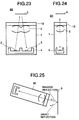
- the sensor is tilted relative to the bar code as shown in Fig. 25 so that the reflected-beam contains a less amount of direct-reflection with an increased ratio of scattered light to the direct-reflection.
- a tilted photo-interrupter occupies a larger space within the housing of the interrupter, presenting a problem in assembling into the apparatus.
- incorporating such a photo-interrupter in the apparatus is an obstacle to miniaturizing the apparatus.
- the present invention was made in view of the problems noted above.
- An object of the invention is to provide an optical device which lends itself to the miniaturization of apparatus.
- Another object of the invention is to provide an optical device which ensures that for example bar codes are reliably read regardless of the luster of the surface of a medium on which the bar code is printed.
- a light-emitting element (2) emits a first beam of light or read-beam (2a).
- a lens cover (18) has an inclined surface (8a) that is a an angle with the read-beam (2a) and reflects the read-beam (2a) toward a bar code (6), the read-beam (2a) emerging as a second beam of light or reflected-beam (3a) after reflection from the surface of the bar code (6).
- the reflected-beam (3a) contains components directly reflected from the bar code (6) and randomly reflected by the white and black areas of the bar code (6).
- An optical system in the form of a lens (5) is arranged between the lens cover (8) and the light-emitting element (2), and converges the read-beam (2a) to the bar code (6).
- the inclined surface (8a) is also at an angle with the reflected-beam and reflects the reflected-beam (3a) toward a second optical system in the form of a lens (5) which in turn converges the reflected-beam (3a) emerging from the inclined surface (8a) to a light-sensing element (3).
- the light-sensing element sensing the reflected-beam (3a).
- the inclination angle of the inclined surface (8a) may be selected such that more randomly reflected light is contained in the reflected-beam (3a) than the directly reflected light.
- FIGs. 1 and 2 are sectional views of an optical device (photo-interrupter 10) according to a first embodiment of present invention.
- a light-emitting chip 2 emits a read-beam, and a light-sensing chip 3 for sensing the read-beam reflected off the surface (herein referred to as "reflected-beam") of a bar code 6 as an object to be read.
- the bar code 6 includes white and black areas as shown.
- the light-emitting chips 2 and light-sensing chip 3 are mounted on a head 4.
- a lens 5 is held above the light-emitting chip 2 and light-sensing chip 3, and includes a lens section 5a and lens section 5b, the lens 5a focusing the read-beam from light-emitting chip 2 on the bar code 6 and the lens 5b focusing the reflected-beam on the light-sensing chip 3.
- a lens cover 8 is dispose on the lens 5.
- a case 1 houses the head 4, lens cover 8, and other associated components, not shown, therein.
- the above two lens sections 5a and 5b have optical axes 2a and 3a, respectively, which are somewhat oblique to each other.
- a lens cover 8 is made of a transparent material such as glass or resin, and has a surface 8a which is inclined at 45 degrees with respect to the plane PLo including the two optical axes 2a and 3a of the lens 5.
- the plane PLo is also substantially parallel to the surface of the bar code 6.
- Fig. 3 is a perspective view of the optical axes 2a an 2b of the read-beam and reflected beam, respectively.
- the read-beam emitted from light-emitting chip 2 is converged by the lens 5, and is then reflected by the inclined plane 8a of the lens cover 8 to the bar code 6. Since the inclination angle of the inclined surface 8a is 45 degrees, the read-beam and reflected-beam are in a plane substantially perpendicular to the surface of the bar code 6 as shown in Fig. 4.
- the reflected-beam contains diffused reflection (randomly reflected light) and direct reflection Dr, and travels in the optical path 3a back to the photo-interrupter 10.
- the components representing the information on the bar code 6 are redirected by the inclined surface 8a of the lens cover 8 toward the lens section 5b which in turn focuses the light to the light-sensing chip 3.
- the light incident upon the inclined surface 8a is totally reflected if the angle of incidence, i.e., ⁇ 1 is greater than 41.8 degrees.
- the reflected-beam from the bar code 6 is redirected by the inclined surface 8a of the lens cover 8 by reflection.
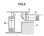
- This construction offers a shorter distance d3 from the photo-interrupter 10 to the bar code 6 while still maintaining a sufficient optical distance d1+d2. Therefore, as shown in Fig. 5, when assembled in an apparatus, the construction of the first embodiment requires a distance d4 in the direction in which the read-beam illuminates the bar code 6, while the conventional construction requires a distance d5 longer than the distance d4.
- the construction of the first embodiment lends itself to the miniaturization of an apparatus into which the photo-interrupter 10 of this construction is installed. It is to be clearly understood that the photo-interrupter 10 of the embodiment takes a smaller space defined by a chassis 15 than the conventional photo-interrupter 80.
- the use of the lens cover 8 of the aforementioned geometry not only protects the lens 5 but also functions the same way as a prism, and therefore eliminates the prism which was needed for redirecting the read-beam in the conventional apparatus. Therefore, equipping an apparatus with this type of photo-interrupter 10 allows cost reduction.
- Figs. 6 and 7 are sectional views of a photo-interrupter as an optical device according to a second embodiment. This embodiment applies to the photo-interrupter 20 just as the first embodiment described above. Structural elements in Figs. 6 and 7 similar to or corresponding to those in Figs. 1 and 2 have been given the same reference numerals.
- a head 4 supports a light-emitting chip 2 and a light-sensing chip 3.
- a lens 5 is held above the light-emitting chip 2 and light-sensing chip.
- a lens cover 8 is held on the lens 5.
- a case 1 houses the head 4 having the chips 2 and 3 mounted thereon, lens 5, and other associated components, not shown therein.
- the photo-interrupter 20 has a mounting projection 7 by which the photo-interrupter 20 is positioned in place when the photo-interrupter 20 is assembled to a chassis 11 of an apparatus as shown in Fig. 9.
- the chassis 11 is not transparent to light, preventing ambient light from entering the apparatus.
- the mounting projection 7 is on the surface of the photo-interrupter 20 opposing the bar code 6.
- the mounting projection 7 is a cylinder of a transparent material.
- the diameter L2 of the mounting projection should be large enough so as not to block the read-beam having a diameter D1 when the read-beam emerges the mounting projection 7.
- the shaded area represents the divergence of light.
- the diameter L2 is selected to be as large as the components of the reflected-beam that would fall on the light-sensing element 3 are not blocked. If the interior surface is highly reflective, the diameter should be as small as possible so that only the light converged by the lens 5 enters the light-emitting chip.
- the chassis 11 of an apparatus into which the photo-interrupter 20 is formed with a mounting hole 12 therein.
- the mounting projection 7 is inserted into the mounting hole 12, as shown in Fig. 10.
- the diameter of the mounting hole 12 is such that the mounting projection 7 snugly fits thereinto, the photo-interrupter 20 is firmly connected to block 11. Such a diameter facilitates the assembly operation of the photo-interrupter 20.
- the position of the photo-interrupter 20 can be easily adjusted after insertion of the mounting projection 7, in which case the photo-interrupter 20 is fixedly assembled to the chassis 11 by a suitable method such as bonding by an adhesive, melting, or holding with the other structural elements of the chassis 11.
- the photo-interrupter 20 is assembled to the chassis 11 with the mounting projection 7 which also functions as the optical path for the read-beam and reflected-beam.
- the read-beam emerging the photo-interrupter 20 is more accurately positioned relative to the chassis 11 when the photo-interrupter 20 is positioned with reference to the mounting projection 7 than with reference to other part, e.g., near the head 4, of the photo-interrupter 20.
- the use of mounting projection as a positional reference minimizes variations in optical characteristics.
- Fig. 11 is a cross-sectional side view of the apparatus into which the photo-interrupter 20 is assembled.
- the read-beam and reflected-beam are output and input, respectively, through the mounting projection 7 which serves as a positional reference when the photo-interrupter 20 is assembled to the chassis 11. Therefore, even if the position of the rest of the photo-interrupter 30 changes slightly relative to chassis 11, the focus position of photo-interrupter 30 relative to the chassis 11 will not shift.
- the mounting projection 7 may be other shapes in which case the shape of the hole 12 is in accordance with the shape of the mounting projection 7.
- rotation of the photo-interrupter if not desired, can be prevented by forming the mounting projection 7 in the form of, for example, a prism.
- the read-beam travels in the plane substantially perpendicular to the surface of the bar code 6 as shown in Fig. 4 and the direct reflection travels back together with diffused reflection in the same plane entering the lens cover 8.
- the direct reflection may reach the light-sensing element 3.
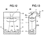
- Figs. 12 and 13 are sectional views of an optical device according to a third embodiment of the present invention. Components in Figs. 12 and 13 corresponding to those in Figs. 1, 2, 6, and 7 have been given the same or similar reference numerals.
- a head 4 supports a light-emitting chip 2 and a light-sensing chip 3 thereon.
- a lens 5 is held above the light-emitting chip 2 and light-sensing chip.
- a case 1 houses the lens 5, head 4, and other associated components, not shown.
- a lens cover 8 is held on the lens 5 and has a mounting projection 7 formed therewith. The mounting projection 7 is on the surface of the photo-interrupter 30 opposing the bar code 6.
- the inclined surface 8a of the lens cover 8 of the photo-interrupter 30 shown in Fig. 13 is at angles ⁇ 2 other than 45 degrees, e.g., 55 degrees, with the plane including the two optical axes 2a and 3a, as opposed to the inclined surface 8a of the photo-interrupter 20 shown in Figs. 6 and 7 which is at an angle ⁇ 1 at 45 degrees with the plane including the two optical axes. It is to be noted that this angle ⁇ 2 is such that a significant amount of direct reflection will not enter the mounting projection 7.
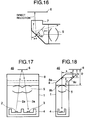
- the read-beam travels along the optical axis 2a in a plane PL1 in Fig. 14 and the diffused reflection travels along the optical axis 3a in the plane PL1 while the direct reflection travels along an optical axis Dr in a plane PL2.
- the planes PL1 and PL2 make an angle ⁇ 1 with the surface of the bar code 6.
- the reflected-beam shown in solid line enters the mounting projection 7 and is converged by the lens 5 to the light-sensing element 3.
- Some of the direct reflection shown in dotted line enters the mounting projection 7 but is not converged by the lens 5 to the light-sensing element 3. Thus, the direct reflection will not reach the light-sensing element 3.
- the read-beam travels along the optical axis 2a in a plane PL3 in Fig. 15 and the diffused reflection is reflected back along the optical axis 3a in the plane PL3 into the mounting projection 7 while the direct reflection travels along an optical axis Dr in a plane PL4.
- the planes PL3 and PL4 make an angle ⁇ 2 with the surface of the bar code 6.
- some of the direct reflection enters the mounting projection 7 but is not converged by the lens 5 to the light-sensing element 3.
- the direct reflection will not reach the light-sensing element 3.
- the angles ⁇ 1 and ⁇ 2 are shown somewhat larger than actual values in order to clearly illustrate the planes in which the light incident upon the bar code 6 and light reflected by the bar code 6 travel.
- the angle ⁇ 2 varies depending on the diameter of the mounting projection 7 and the distance from the mounting projection 7 to the bar code 6.
- the light incident upon the light-sensing element 3 contains the direct reflection and scattered light in different proportion with greatly increased ratio of the scattered light to the direct reflection.
- the intensity of direct reflection is high but varies depending not only on the black and white surfaces of the bar code but also on the luster of the object on which the bar code is printed. For example, if the area concerned is black and the surface is glossy, the intensity becomes high making it difficult to distinguish between the black and white surfaces. On the other hand, the intensity of the diffused reflection is low, but is not affected significantly by the luster of the surface. Therefore, if the ratio of the scattered light to the direct reflection is increased, the overall intensity of the light incident upon the light-sensing element 3 decreases but becomes less sensitive to the luster of an object to be measured. The signal-to-noise ratio of the light incident upon the light-sensing element 3 can therefore be increased.
- the inclination angle ⁇ 2 of the surface 8a is increased or decreased from 45 degrees, the percentage of the direct reflection in the reflected-beam can be reduced.
- the refraction index of the lens cover 8 is, for example, 1.5 and the incidence angle (i.e. inclination angle) is 41.8 degrees or more, the read-beam is totally reflected. Therefore, the inclination angle ⁇ 2 can be set between 41.8 degrees and 45 degrees.
- the inclination angles ⁇ 2 other than 45° cause the read-beam to be incident on the bar code at an angle ⁇ 3 other than 90° , causing the light directly reflected by the lustrous surface of the bar code 6 to travel in such directions as not to enter the mounting projection 7.
- the inclination angle ⁇ 2 be 45 degrees or larger.
- An inclination angle of the surface 8a other than 45 degrees increases the ratio of the scattered light contained in the light reflected by the bar code 6, and therefore improves the signal-to-noise ratio of the light incident upon the light-sensing element 3.
- the inclination angle of the surface 8a greater than 45 degrees ensures that the light is totally reflected, so that no part of light passes through the surface 8a to the outside of the photo-interrupter.
- Figs. 17 and 18 are sectional views of an optical device according to a fourth embodiment. Structural elements in Figs. 17 and 18 similar to or corresponding to those in Figs. 1, 2, 6, 7, 14 and 15 have been given the same reference numerals.
- Figs. 17 and 18 illustrate a photo-interrupter 40 of the fourth embodiment.
- a head 4 supports a light emitting chip 2 and light sensing chip 3 thereon. Over the light emitting chip 2 and light sensing chip 3 is held a lens 5.
- a lens cover 8 is mounted on the lens 5.
- a case 1 houses the head 4, light emitting chip 2 and light sensing chip 3, lens 5, lens cover 8, and other associated components, not shown.
- the lens cover 8 has two inclined surfaces 8a and 8c, substantially parallel to each other.
- the optical distance from the bar code 6 to the bottom surface 8b of the lens cover 8 in contact with the lens 5 is d1+d2.
- the optical distance from the bar code 6 to the bottom surface 8b is a+b+c .
- the use of two surfaces 8a and 8c makes the physical distance D, from the bar code 6 to the bottom surface 8b, shorter by the distance a while still maintaining the optical distance a+b+c .
- the distance a can be determined at will by adjusting the space between two inclined surfaces 8a and 8c. Therefore, these two surfaces 8a and 8c may be advantageously used in reducing the overall size of an apparatus which incorporates the photo-interrupter 40.
- the aforementioned two surfaces 8a and 8c provide a detour of light, increasing degrees of freedom in designing the apparatus.
- the shorter physical distance D resulting from the two surfaces 8a and 8b is an advantage to miniaturizing the apparatus.
- the first to fourth embodiments have been described with reference to a reflection type photo-interrupter to which the present invention is applied.
- a fifth embodiment is directed to the construction of a light-emitting element 50 and a light-sensing element 50a as shown in Fig. 20.
- Fig. 20 illustrates the light-emitting element 50.
- the light-emitting element 50 and the light-sensing element 50a are of much the same construction and differ only in that the light emitting chip 2 and a light-sensing element 3 are interchanged.
- the solid lines indicate the light emitted by the light-sensing element 50 and the dotted lines indicate the light coming in the light light-sensing element 50a.
- the light-emitting element 50 includes a light emitting chip 2 and a package 21 which is made of a transparent resin and houses light emitting chip 2 therein.
- the package 21 includes an inclined surface 22 which functions as a reflecting surface in the same way as the inclined surface 8a formed, for example, on the lens cover 8 shown in Fig. 1.
- the light-sensing element 50a includes a light sensing chip 3 in place of the light emitting chip 3 in the light-emitting element 50.
- the surface 22 formed on a part of the package 21 for the light-emitting element 50 and the light-sensing element 50a offers more degrees of freedom of the arrangement thereof. Therefore, an apparatus incorporating the light-emitting element 50 and/or the light-sensing element 50a can realize package reduction.
- a sixth embodiment is directed to the construction of a light-emitting element and a light-sensing element which have two inclined reflecting surfaces.
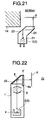
- Fig. 21 illustrates a light-emitting element 60 and a light-sensing element 60a according to the sixth embodiment.
- the solid lines indicate the light emitted by the light-sensing element 60 and the dotted lines indicate the light coming in the light light-sensing element 60a.
- the light-emitting element 60 and the light-sensing element 60a are of much the same construction and differ only in that the light emitting chip 2 and a light-sensing element 3 are interchanged.
- This light-emitting element 60 includes a package 21 in the form of, for example, a transparent resin in which a light-emitting chip 2 is molded.
- the package has two inclined surfaces that function as a reflecting surface similar to the surfaces 8a and 8c in the fourth embodiment (Fig. 18).
- the light-sensing element 60a has the light sensing chip 3 in place of the light sensing chip 3 in the light-emitting element 60.
- the two surfaces 23 and 24 provide a detour of light so that the obstacle 14 is cleared.
- the construction increases degrees of freedom in designing the apparatus.
- the package 21 having the two inclined surfaces 23 and 24 is an advantage to miniaturizing the apparatus into which the light-emitting element 60 and/or the light-sensing element 60a is incorporated.
- Fig. 22 illustrates a photo-interrupter 70 according to a seventh embodiment.
- the seventh embodiment includes a reflecting mirror 25 in place of the inclined surface 8a of the aforementioned first to fourth embodiments.
- a head 4 supports a light-emitting element 2 and light-sensing element 3 thereon.
- a lens 5 is held over the head 4 and has two sections as in the first embodiment, only one being shown in the figure.
- One of the two sections has an optical axis in line with the optical axis of the read-beam and the other has an optical axis in line with the optical axis of the scattered light incident on the light-sensing element 3.
- a case 1' has an inclined wall on its top and a mirror 25 placed on the interior side of the inclined wall.
- the case 1' also has an opening 8d covered by a lens cover 8' through which the read-beam emitted from the light-emitting element 2 emerges and the reflected-beam enters.
- the mirror 25 reflects the read-beam converged by the lens 5 to direct the read-beam to the bar code 6.
- the mirror 25 also directs the reflected-beam from the surface of the bar code 6 to the lens 5 which in turn converges the light to light-sensing chip 3.
- the photo-interrupter 70 is advantageous in that a small sized apparatus incorporating the photo-interrupter 99 is manufactured at lower costs.
Abstract
Description
Claims (14)
- An optical device comprising:a light-emitting element (2), emitting a first beam of light;a first reflector (8a), reflecting said first beam of light toward a surface of an object, said first beam of light emerging as a second beam of light after reflection from the surface of the object;a first optical system (5a) arranged between said light-emitting element and said first reflector, said first optical system converging said first beam of light substantially to the surface of the object;a light-sensing element (3), sensing said second beam of light;a second reflector (8a), reflecting said second beam of light toward said light-sensing element;a second optical system (5b) arranged between said light-sensing element (3) and said second reflector (8a), said second optical system (5b) converging said second beam of light substantially to said the light-sensing element (3).
- The optical device of Claim 1, further including a light-blocking member (1, 11) for preventing ambient eight from entering.
- The optical device of Claim 1, wherein said light-sensing element has an additional reflector for reflecting the second beam of light to change its direction of travel.
- The optical device of Claim 1, wherein said light-emitting element has an additional reflector for reflecting the first beam of light to change its direction of travel.
- The optical device of Claim 4, wherein said additional reflector (8c) is parallel with said first and second reflectors, said first beam of light is reflected by said first reflector and subsequently by said additional reflector.
- The optical device of Claim 1, wherein said first and second optical systems are lenses (5a, 5b).
- The optical device of Claim 1, further including a transparent cover (8) having a flat surface (8a), said cover (8) protecting said first and second optical systems (5a, 5b), wherein said first and second reflectors are formed of said flat surface (8a).
- The optical device of Claim 7, wherein said cover (8) is provided with a projection (7) by means of which said device is positioned relative to an apparatus when said device is assembled to the apparatus.
- The optical device of Claim 1, wherein said first and second reflectors are formed in a single common reflecting flat surface (8a).
- The optical device of Claim 9, wherein said single common reflecting flat surface is a mirror (25).
- The optical device of Claim 9, wherein said second beam of light contains direct reflection and diffused reflection and said reflecting surface is at an angle with said first and second beams of light, and said angle being such that more diffused reflection is contained in said second beam of light than the direct reflection.
- The optical device of Claim 3, wherein said additional reflector (8c) is parallel with said first and second reflectors, and said second beam of light is reflected by said additional reflector and subsequently by said second reflector.
- A method of reading a bar code comprising:illuminating an object having the bar code thereon with light from a source (2) thereof,collecting light returned from the object with an optical system which preferentially collects light bearing data concerning the bar code rather than specular reflections from the object bearing the bar code,and detecting the intensity of the light bearing the bar code data.
- A method according to claim 13 including reflecting the light returned from the object such as to, at least in part, separate the specular reflections from the light bearing data concerning the bar code, and forming a converging beam from the reflected light, directed towards a detector (3) that performs the detecting of the intensity thereof.
Applications Claiming Priority (3)
| Application Number | Priority Date | Filing Date | Title |
|---|---|---|---|
| JP25608496 | 1996-09-27 | ||
| JP256084/96 | 1996-09-27 | ||
| JP25608496A JP3824357B2 (en) | 1996-09-27 | 1996-09-27 | Optical semiconductor device |
Publications (4)
| Publication Number | Publication Date |
|---|---|
| EP0833273A2 true EP0833273A2 (en) | 1998-04-01 |
| EP0833273A3 EP0833273A3 (en) | 1998-12-16 |
| EP0833273B1 EP0833273B1 (en) | 2003-05-28 |
| EP0833273B8 EP0833273B8 (en) | 2003-10-01 |
Family
ID=17287677
Family Applications (1)
| Application Number | Title | Priority Date | Filing Date |
|---|---|---|---|
| EP97301688A Expired - Lifetime EP0833273B8 (en) | 1996-09-27 | 1997-03-13 | Optical device |
Country Status (5)
| Country | Link |
|---|---|
| US (1) | US5925867A (en) |
| EP (1) | EP0833273B8 (en) |
| JP (1) | JP3824357B2 (en) |
| KR (1) | KR100374244B1 (en) |
| DE (1) | DE69722339T2 (en) |
Cited By (6)
| Publication number | Priority date | Publication date | Assignee | Title |
|---|---|---|---|---|
| WO2000016239A1 (en) * | 1998-09-11 | 2000-03-23 | Accu-Sort Systems, Inc. | Quasi-coaxial optical bar code reader |
| WO2001084542A2 (en) * | 2000-05-03 | 2001-11-08 | Novo Nordisk A/S | Coding of cartridges for an injection device |
| US6533183B2 (en) | 2000-05-03 | 2003-03-18 | Novo Nordisk A/S | Coding of cartridges for an injection device |
| WO2009047810A1 (en) * | 2007-09-07 | 2009-04-16 | Datalogic Scanning Group S.R.L. | Image acquisition device and optical component thereof |
| US9522238B2 (en) | 2005-05-10 | 2016-12-20 | Novo Nordisk A/S | Injection device comprising an optical sensor |
| US9950117B2 (en) | 2009-02-13 | 2018-04-24 | Novo Nordisk A/S | Medical device and cartridge |
Families Citing this family (12)
| Publication number | Priority date | Publication date | Assignee | Title |
|---|---|---|---|---|
| US6634558B1 (en) * | 1998-08-12 | 2003-10-21 | Symbol Technologies, Inc. | Optical code reader with hand mounted imager |
| EP1309366B1 (en) * | 2000-08-10 | 2007-02-21 | Novo Nordisk A/S | Medication delivery device comprising a support for a cartridge |
| US6685092B2 (en) * | 2001-06-15 | 2004-02-03 | Symbol Technologies, Inc. | Molded imager optical package and miniaturized linear sensor-based code reading engines |
| KR20030089035A (en) * | 2002-05-15 | 2003-11-21 | (주)선진비알티 | Two-Dimensional Barcode Scanning Module |
| JP4026578B2 (en) * | 2003-10-16 | 2007-12-26 | 株式会社デンソーウェーブ | Optical information reader |
| US8638108B2 (en) * | 2005-09-22 | 2014-01-28 | Novo Nordisk A/S | Device and method for contact free absolute position determination |
| WO2007107562A2 (en) * | 2006-03-20 | 2007-09-27 | Novo Nordisk A/S | Contact free reading of cartridge identification codes |
| EP2011223B1 (en) | 2006-04-12 | 2018-06-13 | Novo Nordisk A/S | Absolute position determination of movably mounted member in medication delivery device |
| RU2431805C2 (en) * | 2006-04-26 | 2011-10-20 | Ново Нордиск А/С | Method of contactless determination of medicine delivery device movable element position |
| WO2008113772A1 (en) * | 2007-03-21 | 2008-09-25 | Novo Nordisk A/S | A medical delivery system having container recognition and container for use with the medical delivery system |
| DE602008002762D1 (en) * | 2007-06-09 | 2010-11-04 | Novo Nordisk As | CONTACT-FREE READING OF MEMORY IDENTIFICATION CODES |
| EP2352536B1 (en) | 2008-11-06 | 2018-03-14 | Novo Nordisk A/S | Electronically assisted drug delivery device |
Citations (5)
| Publication number | Priority date | Publication date | Assignee | Title |
|---|---|---|---|---|
| EP0057370A2 (en) * | 1981-02-02 | 1982-08-11 | International Business Machines Corporation | Optical scanner |
| EP0377973A2 (en) * | 1989-01-12 | 1990-07-18 | Hewlett-Packard Company | Sensor array and illumination system for a large depth-of-field bar code scanner |
| EP0475675A2 (en) * | 1990-09-13 | 1992-03-18 | Minnesota Mining And Manufacturing Company | Optical reader |
| EP0587113A2 (en) * | 1992-09-10 | 1994-03-16 | United Parcel Service Of America, Inc. | Improved lighting apparatus for the computer imaging of a surface |
| EP0669592A1 (en) * | 1993-08-17 | 1995-08-30 | Sony Corporation | Optical device for code reader |
Family Cites Families (14)
| Publication number | Priority date | Publication date | Assignee | Title |
|---|---|---|---|---|
| US3753249A (en) * | 1967-01-30 | 1973-08-14 | D Silverman | Information systems using arrays of multiple spot patterns |
| US3611292A (en) * | 1969-05-21 | 1971-10-05 | Texaco Inc | Credit card validation system |
| US4805175A (en) * | 1987-12-03 | 1989-02-14 | Metrologic Instrumetns, Inc. | Ultra-compact, hand-held laser scanner |
| US4871904A (en) * | 1987-12-28 | 1989-10-03 | Symbol Technologies, Inc. | Multidirectional optical scanner |
| KR910008421B1 (en) * | 1988-05-24 | 1991-10-15 | 주식회사 금성사 | A method for detecting barcode of barcode reader using hologram scanner and its scanning optical system |
| US5053612A (en) * | 1990-03-28 | 1991-10-01 | Tech-S, Inc. | Barcode badge and ticket reader employing beam splitting |
| US5449892A (en) * | 1991-10-29 | 1995-09-12 | Nippondenso Co., Ltd. | Information reading apparatus |
| JP2911700B2 (en) * | 1992-02-17 | 1999-06-23 | 三菱電機株式会社 | Code reading pattern imaging device |
| EP0573702A1 (en) * | 1992-06-10 | 1993-12-15 | KIHN S.à.r.l. | Method of making or transition section of a rail and rail made by this method |
| JP2812072B2 (en) * | 1992-06-19 | 1998-10-15 | 富士通株式会社 | Information reading device |
| US5350909A (en) * | 1992-10-14 | 1994-09-27 | International Business Machines Corp. | Optical scanner for bar code scanning |
| US5498862A (en) * | 1993-05-06 | 1996-03-12 | International Computers Limited | Side scanning bar code reader with vertical and horizontal scan patterns |
| JP3435200B2 (en) * | 1993-11-29 | 2003-08-11 | ペンタックス株式会社 | Image reading device |
| US5572007A (en) * | 1994-08-19 | 1996-11-05 | Intermec Corporation | Symbology reader with interchangeable window |
-
1996
- 1996-09-27 JP JP25608496A patent/JP3824357B2/en not_active Expired - Lifetime
-
1997
- 1997-03-10 US US08/814,259 patent/US5925867A/en not_active Expired - Fee Related
- 1997-03-13 DE DE69722339T patent/DE69722339T2/en not_active Expired - Lifetime
- 1997-03-13 EP EP97301688A patent/EP0833273B8/en not_active Expired - Lifetime
- 1997-04-30 KR KR1019970016713A patent/KR100374244B1/en not_active IP Right Cessation
Patent Citations (5)
| Publication number | Priority date | Publication date | Assignee | Title |
|---|---|---|---|---|
| EP0057370A2 (en) * | 1981-02-02 | 1982-08-11 | International Business Machines Corporation | Optical scanner |
| EP0377973A2 (en) * | 1989-01-12 | 1990-07-18 | Hewlett-Packard Company | Sensor array and illumination system for a large depth-of-field bar code scanner |
| EP0475675A2 (en) * | 1990-09-13 | 1992-03-18 | Minnesota Mining And Manufacturing Company | Optical reader |
| EP0587113A2 (en) * | 1992-09-10 | 1994-03-16 | United Parcel Service Of America, Inc. | Improved lighting apparatus for the computer imaging of a surface |
| EP0669592A1 (en) * | 1993-08-17 | 1995-08-30 | Sony Corporation | Optical device for code reader |
Cited By (10)
| Publication number | Priority date | Publication date | Assignee | Title |
|---|---|---|---|---|
| WO2000016239A1 (en) * | 1998-09-11 | 2000-03-23 | Accu-Sort Systems, Inc. | Quasi-coaxial optical bar code reader |
| AU751183B2 (en) * | 1998-09-11 | 2002-08-08 | Accu-Sort Systems, Inc. | Quasi-coaxial optical bar code reader |
| US6808115B2 (en) | 1998-09-11 | 2004-10-26 | Accu-Sort Systems, Inc. | Quasi-coaxial optical bar code reader |
| WO2001084542A2 (en) * | 2000-05-03 | 2001-11-08 | Novo Nordisk A/S | Coding of cartridges for an injection device |
| WO2001084542A3 (en) * | 2000-05-03 | 2002-04-18 | Novo Nordisk As | Coding of cartridges for an injection device |
| US6533183B2 (en) | 2000-05-03 | 2003-03-18 | Novo Nordisk A/S | Coding of cartridges for an injection device |
| US9522238B2 (en) | 2005-05-10 | 2016-12-20 | Novo Nordisk A/S | Injection device comprising an optical sensor |
| WO2009047810A1 (en) * | 2007-09-07 | 2009-04-16 | Datalogic Scanning Group S.R.L. | Image acquisition device and optical component thereof |
| US8413902B2 (en) | 2007-09-07 | 2013-04-09 | Datalogic Scanning Group S.R.L. | Image acquisition device and optical component thereof |
| US9950117B2 (en) | 2009-02-13 | 2018-04-24 | Novo Nordisk A/S | Medical device and cartridge |
Also Published As
| Publication number | Publication date |
|---|---|
| EP0833273B8 (en) | 2003-10-01 |
| KR19980024012A (en) | 1998-07-06 |
| US5925867A (en) | 1999-07-20 |
| EP0833273A3 (en) | 1998-12-16 |
| KR100374244B1 (en) | 2003-05-12 |
| JP3824357B2 (en) | 2006-09-20 |
| EP0833273B1 (en) | 2003-05-28 |
| DE69722339D1 (en) | 2003-07-03 |
| DE69722339T2 (en) | 2004-02-05 |
| JPH10105635A (en) | 1998-04-24 |
Similar Documents
| Publication | Publication Date | Title |
|---|---|---|
| EP0833273B1 (en) | Optical device | |
| US5473149A (en) | Bar code reading apparatus with multifocal length optical system | |
| US6507015B1 (en) | Raindrop sensor having plano-convex lens | |
| JP4702200B2 (en) | RECEIVER AND RADAR DEVICE PROVIDED WITH THE RECEIVER | |
| US4753498A (en) | Optical reader | |
| KR970060089A (en) | Optical output controller of surface-emitting laser and optical pickup device employing the same | |
| US4968876A (en) | Laser beam reader having a projecting and receiving optical system | |
| JP3580676B2 (en) | Optical scanning device and light source module | |
| KR940013109A (en) | Close Image Sensor | |
| JP3603308B2 (en) | Optical device for code reader | |
| US6715683B2 (en) | Optical data code reader | |
| KR940006094A (en) | Optical information processing device | |
| JP2776715B2 (en) | Optical reader | |
| JP2750593B2 (en) | Optical system of laser reader | |
| NL1007368C2 (en) | Optical recording system. | |
| KR100355329B1 (en) | Device for reading pattern with projections | |
| JP2795293B2 (en) | Bar code reader | |
| JPH02101595A (en) | Bar-code scanner | |
| JP2000019110A (en) | Refractive index measuring apparatus | |
| EP0709798A1 (en) | Wand scanner with a sensor supported by a hole in illuminating optics | |
| JP2725511B2 (en) | Symbol reader | |
| JPH103691A (en) | Optical pickup device | |
| JP2825108B2 (en) | Barcode information reader | |
| KR930006882Y1 (en) | Lens structure of portable laser scanner head | |
| KR100573583B1 (en) | A device for arranging a chip mounter |
Legal Events
| Date | Code | Title | Description |
|---|---|---|---|
| PUAI | Public reference made under article 153(3) epc to a published international application that has entered the european phase |
Free format text: ORIGINAL CODE: 0009012 |
|
| AK | Designated contracting states |
Kind code of ref document: A2 Designated state(s): DE FR GB |
|
| PUAL | Search report despatched |
Free format text: ORIGINAL CODE: 0009013 |
|
| AK | Designated contracting states |
Kind code of ref document: A3 Designated state(s): DE FR GB |
|
| 17P | Request for examination filed |
Effective date: 19990330 |
|
| AKX | Designation fees paid |
Free format text: DE FR GB |
|
| 17Q | First examination report despatched |
Effective date: 20011029 |
|
| GRAG | Despatch of communication of intention to grant |
Free format text: ORIGINAL CODE: EPIDOS AGRA |
|
| GRAG | Despatch of communication of intention to grant |
Free format text: ORIGINAL CODE: EPIDOS AGRA |
|
| GRAH | Despatch of communication of intention to grant a patent |
Free format text: ORIGINAL CODE: EPIDOS IGRA |
|
| GRAH | Despatch of communication of intention to grant a patent |
Free format text: ORIGINAL CODE: EPIDOS IGRA |
|
| GRAA | (expected) grant |
Free format text: ORIGINAL CODE: 0009210 |
|
| AK | Designated contracting states |
Designated state(s): DE FR GB |
|
| REG | Reference to a national code |
Ref country code: GB Ref legal event code: FG4D |
|
| REF | Corresponds to: |
Ref document number: 69722339 Country of ref document: DE Date of ref document: 20030703 Kind code of ref document: P |
|
| RIN2 | Information on inventor provided after grant (corrected) |
Inventor name: HAGIMOTO, MITSURU |
|
| ET | Fr: translation filed | ||
| PLBE | No opposition filed within time limit |
Free format text: ORIGINAL CODE: 0009261 |
|
| STAA | Information on the status of an ep patent application or granted ep patent |
Free format text: STATUS: NO OPPOSITION FILED WITHIN TIME LIMIT |
|
| 26N | No opposition filed |
Effective date: 20040302 |
|
| REG | Reference to a national code |
Ref country code: GB Ref legal event code: 732E Free format text: REGISTERED BETWEEN 20090416 AND 20090422 |
|
| REG | Reference to a national code |
Ref country code: FR Ref legal event code: TP |
|
| PGFP | Annual fee paid to national office [announced via postgrant information from national office to epo] |
Ref country code: FR Payment date: 20100324 Year of fee payment: 14 |
|
| PGFP | Annual fee paid to national office [announced via postgrant information from national office to epo] |
Ref country code: GB Payment date: 20100310 Year of fee payment: 14 |
|
| PGFP | Annual fee paid to national office [announced via postgrant information from national office to epo] |
Ref country code: DE Payment date: 20100415 Year of fee payment: 14 |
|
| GBPC | Gb: european patent ceased through non-payment of renewal fee |
Effective date: 20110313 |
|
| REG | Reference to a national code |
Ref country code: FR Ref legal event code: ST Effective date: 20111130 |
|
| PG25 | Lapsed in a contracting state [announced via postgrant information from national office to epo] |
Ref country code: FR Free format text: LAPSE BECAUSE OF NON-PAYMENT OF DUE FEES Effective date: 20110331 Ref country code: DE Free format text: LAPSE BECAUSE OF NON-PAYMENT OF DUE FEES Effective date: 20111001 |
|
| REG | Reference to a national code |
Ref country code: DE Ref legal event code: R119 Ref document number: 69722339 Country of ref document: DE Effective date: 20111001 |
|
| PG25 | Lapsed in a contracting state [announced via postgrant information from national office to epo] |
Ref country code: GB Free format text: LAPSE BECAUSE OF NON-PAYMENT OF DUE FEES Effective date: 20110313 |