EP0833270A2 - Method and device for detecting optically detectable informations being disposed potentially on objects with a great area - Google Patents
Method and device for detecting optically detectable informations being disposed potentially on objects with a great area Download PDFInfo
- Publication number
- EP0833270A2 EP0833270A2 EP97114359A EP97114359A EP0833270A2 EP 0833270 A2 EP0833270 A2 EP 0833270A2 EP 97114359 A EP97114359 A EP 97114359A EP 97114359 A EP97114359 A EP 97114359A EP 0833270 A2 EP0833270 A2 EP 0833270A2
- Authority
- EP
- European Patent Office
- Prior art keywords
- line
- camera
- line scan
- plane
- information
- Prior art date
- Legal status (The legal status is an assumption and is not a legal conclusion. Google has not performed a legal analysis and makes no representation as to the accuracy of the status listed.)
- Granted
Links
Images


Classifications
-
- G—PHYSICS
- G06—COMPUTING; CALCULATING OR COUNTING
- G06K—GRAPHICAL DATA READING; PRESENTATION OF DATA; RECORD CARRIERS; HANDLING RECORD CARRIERS
- G06K7/00—Methods or arrangements for sensing record carriers, e.g. for reading patterns
- G06K7/10—Methods or arrangements for sensing record carriers, e.g. for reading patterns by electromagnetic radiation, e.g. optical sensing; by corpuscular radiation
- G06K7/10544—Methods or arrangements for sensing record carriers, e.g. for reading patterns by electromagnetic radiation, e.g. optical sensing; by corpuscular radiation by scanning of the records by radiation in the optical part of the electromagnetic spectrum
- G06K7/10821—Methods or arrangements for sensing record carriers, e.g. for reading patterns by electromagnetic radiation, e.g. optical sensing; by corpuscular radiation by scanning of the records by radiation in the optical part of the electromagnetic spectrum further details of bar or optical code scanning devices
- G06K7/10861—Methods or arrangements for sensing record carriers, e.g. for reading patterns by electromagnetic radiation, e.g. optical sensing; by corpuscular radiation by scanning of the records by radiation in the optical part of the electromagnetic spectrum further details of bar or optical code scanning devices sensing of data fields affixed to objects or articles, e.g. coded labels
Definitions
- the present invention relates to a method and an apparatus for detecting potentially large-area objects, optically detectable information.
- an object with a potentially large surface area is inserted into the Brought field of view of a video camera and those recognizable in the field of view of the video camera Information is integrated into one for the purpose of identification and / or assignment of the object Computer system entered.
- the corresponding device therefore has a video camera and an input device for the information from that captured by the video camera Field of view.
- the optically detectable information on the surface is used of an object often only a small part of its area, especially if it is is a very large object.
- an object from whose surface information is to be acquired actually has a large (generally flat) surface, but this area can may also be relatively small in individual cases, however, the method and the device therefor are designed, the information is essentially independent of the size of the area and itself then to grasp well and precisely if the object in question has a very large surface area while the relevant information may only be a small part of it Claim surface.
- Surface is used in the sense of the present description generally refers to the surface of an object directly facing the camera, the Distance from the camera can vary within the depth of field of the camera optics and the possibly uneven, for example more or less wavy.
- a parcel distribution system provides a typical example of corresponding methods and devices.
- parcels of various sizes are opened Delivered conveyor belts, the conveyor belts are generally designed to Packets up to a predetermined maximum size without the packets necessarily all have to be the maximum size.
- the present invention is intended not be limited to parcel distribution systems, but can also be used in production processes for Sorting and distribution systems or the like are used. The following description takes however, for the sake of better comprehensibility, mainly due to the specific example of Parcel distribution system cover.
- Packets of one can also be used individual size can be arranged on a conveyor belt, so that the camera always has the same distance from the surface of the package.
- these conventional methods are no longer applicable to the post office or other commercial courier companies that ship packages from Accept everyone or at least different customers and to a destination address promote.
- Such packages are at most standardized to the extent that they are a predetermined one Must not exceed the maximum size.
- a common standard is, for example maximum height and width of 900 mm, the length may still be this dimension can exceed.
- such packages have a cuboid shape and a flat shape Interface on which address information, information about the handling of the package or the content (risk of breakage, upward orientation during transport or storage) and Art transportation (for example express goods) are included.
- the present invention is based on the object to create a method and a device of the type mentioned, which also in Situations in which on potentially large surfaces the in a computer system too receiving information can be arranged in any areas of the surface, a remote acquisition and preferably even an automatic acquisition of this information enable.
- this object is achieved in that a high-resolution line camera is used as the video camera, the line length of which in the object distance completely covers the maximum dimensions of an object in this direction, that the object essentially transversely to the longitudinal extension of the image line at an essentially continuous speed is moved through the imaging window or the imaging plane of the line camera and that the image acquisition frequency and the feed speed of the objects are coordinated with one another in such a way that the resolution, that is to say the spacing between successive imaging lines, has at least a comparable magnitude as the resolution within an imaging line.
- the resolution between the lines could deviate by a factor between 1 and 10 from the resolution within the lines, but an embodiment of the method according to the invention is preferred in which the resolution is approximately the same in both directions.
- the orientation of the information on the surface of the object is not fixed either, so that there must be a certain, minimal resolution in each direction. Due to the use of a high-resolution line scan camera, it is possible to display a section of only 100 x 100 mm 2 in sufficient resolution, even on very large objects that have an area of 900 x 1000 mm 2 , for example, in order to display information applied to this area, For example, you can read and enter address labels in normal or fine font size.
- read and “enter” include both reading and entering a person, as well as a mechanical, automatic reading, which if necessary only is checked and confirmed by one person.
- a line scan camera with more than 1000, preferably more than 3000 and especially about 5000 to 7000 pixels along the line. How to calculate easily , 5000 pixels along an image line of, for example, 1000 mm result in a 0.2 mm resolution. This is by far sufficient for conventional inscriptions A person skilled in the art will recognize that a corresponding method also has a resolution of, for example 2000 pixels per 1 meter with a sufficiently large font still with acceptable accuracy would operate. However, a maximum line resolution of 7000 points is preferred.
- the object distance should preferably be more than twice and in particular more than that Three times the maximum width of the objects to be detected.
- This beam path can also be through one or more Mirrors, possibly also deflected by light guides or the like if this leads to Example for limiting the overall height of the overall system appears necessary or expedient
- the relatively large object distance represents a sufficient depth of field for the camera optics sure, which definitely encompasses the area within which the distance of the object surface can vary from the camera optics during the passage through the imaging plane.
- the camera optics or an imaging lens can be recorded and the distance of the line sensor in the line camera of this lens or optics is corresponding to that Distance of the object surface varies.
- a stroke of the order of 1 - 2 mm is sufficient in order to achieve an object distance of at least 3 m height differences of 800 mm in the Balance sharpness.
- the entire surface of the object or the entire partial area containing information of the same are illuminated uniformly, but it is sufficient if the object surface is homogeneously illuminated along the narrow line, which is the intersection of the The surface of the object and the level of the image results in the level of the image spanned by the optical axis of the camera and the line direction.
- the light of the lighting device focuses in this way becomes that a plane of maximum intensity the imaging plane near the surface of the Feed device or in the area of the surface of an object with a maximum distance cuts to camera, i.e. the surfaces of the lowest objects, the widest Distance to the camera are in the imaging plane and thus along the imaging line illuminated with maximum intensity.
- the imaging line has essentially the same apparent brightness, as in the case of the more distant, more intensely illuminated image line.
- the level of the maximum intensity of the lighting preferably has an angle of inclination from at least 0 °, preferably from about 10 ° to 30 ° and at most about 50 ° relative to the imaging plane, the imaging plane preferably in the same direction as that mentioned illumination plane inclined to a perpendicular to the transport surface is.
- the mapping level can be compared to a perpendicular to the transport level, for example be inclined by 20 °, the intersection between the imaging plane and the transport plane in is generally perpendicular to the direction of transport. Regardless of the inclination can however, the mapping level is also one perpendicular to the transport level small angle can be twisted so that the cut line mentioned is no longer perpendicular to Direction of transport runs.
- the simultaneous inclination of the image plane and the illumination plane serves above all Prevention of reflections captured by the camera, such as with reflecting surfaces, such as Example foils and in particular also slightly corrugated foils occur on the object surface could. Such reflections are not in the preferred inclined arrangement or captured in less disturbing form by the camera.
- An embodiment of the method is preferred in which a plurality of line scan cameras are attached to or the surfaces of objects transported on it via several feed devices capture, the line cameras via a storage device and a network with a Main computer and connected to input terminals, where the reproduced object surfaces and the ones to be extracted from them Information can be entered.
- the method according to the invention is used for a parcel distribution system intended.
- the one on which the invention is based Object achieved in that a high-resolution line camera is provided as a video camera is, the camera optics is designed or arranged so that the maximum width of a Object, seen in the direction of the line, is completely detected, and that a feed device is provided which is the object to be detected transversely to the line direction and through the imaging plane of the line scan camera with a substantially more uniform one Speed transported.
- the transport device is preferably a conveyor belt which at least the objects transported in the area of the line scan camera largely free of vibrations.
- the device is preferably designed so that the refresh rate of the Line scan camera and / or the transport speed of the feed device to one another are coordinated controllable.
- the line repetition frequency of the cell camera results in connection with the transport speed of the feed device the distance in succession Figure lines and thus also the distance and the resolution of those to be displayed accordingly Picture lines.
- the line scan camera should have a detection width of 900 mm Have a distance of more than 2 m from the surface of the objects to be imaged.
- the camera is preferably about 4 m above the surface of a conveyor belt for the Objects or arranged at a corresponding optical distance.
- the line scan camera is aligned so that it is defined above Imaging plane is aligned somewhat inclined in the direction of the band plane.
- the corresponding lighting device preferably has a light source whose light is transmitted through a focusing device is bundled in such a way that one plane (with constant distance essentially constant) maximum light intensity both to the level of the feed device and also inclined to the imaging plane of the line scan camera.
- the light source can be used for Example by a row, in the simplest case two, along a line (parallel to the image line) arranged spotlights are formed, each with its own focusing device have, so that the overlapping light intensities of the row of spotlights of the light intensity distribution come relatively close to a homogeneous, linear light source. Doing so through the focusing devices the light is bundled to one side, forming a plane maximum light intensity, i.e.
- a plane which is on the one hand from the linear Light source or the row of spotlights and on the other hand from the directional arrow is spanned in which the maximum light intensity is emitted.
- the lighting device or their focusing device with the light source are then preferably so arranged that the plane of maximum light intensity mentioned above the imaging plane cuts approximately on the surface of the transport device or somewhat above, namely at the level of the surface of an object transported on the transport device minimum height.
- this means that the object is illuminated in this way by the lighting device is that a line of maximum lighting intensity runs across the object results on both sides, i.e. to the previous and the following End of the object, gradually decreasing.
- maximum light intensity relative to the imaging plane is for higher objects the image line at a distance from the line of maximum illumination intensity and parallel to it.
- the inclination of the plane of maximum light intensity and the intensity distribution expediently set so that the lower illuminance of the image lines with higher objects by the shorter camera distance is compensated in such a way that for all objects of different heights approximately the same apparent brightness Figure line or line results.
- the angle between the imaging plane and the maximum plane Light intensity is preferably at least 10 ° and at most 50 °, this being Inclination angle, as well as the inclination of the imaging plane in the same direction contributes to the absence of distracting reflections from reflective surface areas, such as Cover films and the like, are directed into the line scan camera.
- the device according to the invention has several separate ones Feed devices on which each has its own line scan camera with a connected one Sensor computer is arranged, which in turn over a fast data network with several Processing terminals is connected. Because of the high resolution (up to 7000 pixels per Line) and fall at a line repetition frequency in the order of up to 6000 Hertz very large amounts of data, so in the preferred embodiment a data network high performance is used, such as a 100 Mbit Ethernet with a so-called "switching hub" as a switching node.
- each of the sensor computers of the line scan cameras with any of the To connect terminals.
- the number of input terminals is preferably independent of the number of line scan cameras. This feature is provided because, for example, the Acquisition and manual entry of the information data by a user takes longer than the detection of the surface of an object using the line scan camera so that the images the line scan cameras are cached and each from one of the terminals to Processing can be called up.
- the lower image processing speed at the terminals in comparison to the capture of the images by the line scan cameras this is due to a larger one Number of terminals balanced.
- the individual, captured images in the Order of their recording is cached and sent to the individual in exactly this order Terminals passed on, in the order in which the individual terminals turned out to be free report for editing a new image.
- the automatic acquisition and identification of the image information possibly run faster than the detection of the object surfaces, so that in one In such a case, the number of processing terminals could even be smaller than that of the cameras and the associated sensor computer.
- the ratio of the number of terminals to that of the cameras vary accordingly.
- each terminal shows preferably also means for rotating the image or an image detail, preferably by 90 °, by 180 ° or by 270 °, if necessary also by gradual twisting around discrete angular steps.
- each terminal has facilities for manual entry of information data, read from the terminal screen.
- an embodiment of the device according to the invention is particularly preferred which also means for automatic recording of the information data and for Displays of this automatically collected data are provided.
- the Device in addition to a bar or barcode reader also have a plain text reader, wherein with the help of a suitable program, the one saved as a digitized image in the computer Surface of the object is searched for surface areas, which apparently the contain the desired information, which is then converted into corresponding text by plain text software digital symbols are implemented and the result is then on the terminal to Example is displayed in a separate window on a screen.
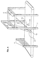
- FIG. 1 A series of line scan cameras can be seen in FIG. 1, of which only four are specifically shown.
- Each of the line scan cameras contains a sensor unit, an auto focus device and one Sensor computer 11, and devices for controlling the sensors, devices for the Image processing, image processing and for communication with a host computer 2 and with Input terminals 3, these tasks at least partially by the sensor computer 11 be taken over.
- the network is e.g. B. a so-called fast Ethernet with a Transmission speed of 100 Mbit per second.
- An essential part of the network 22 forms a switching node 21, which is called “switching hub” in technical terms and which the master computer 2 is controlled and it enables each of the sensor computers 11 with each of the To connect terminals 3, whereupon each of the terminals 3 then has access to the image memory or from the host computer 2 via the switching hub 21 and the network 22 the corresponding Image data is transmitted.
- the individual surfaces captured by the cameras 1 are then as at least partially compressed image data in a buffer in the Sensor computer stored and are sent to one by the host computer 2 in the same order
- the terminals are passed on as soon as such a terminal 3 is ready for processing reports a new picture.
- the sensor computer 11 reports every complete acquisition of the image a surface 9 to the host computer 2, which then displays the images in the appropriate order forwarded to the terminals.
- Terminal 3 for example, then appears on the screen the total surface of a package and with a click of the mouse or with other control devices the user of the terminal then selects the area of the package surface, which contains the requested information.
- FIG. 2 shows a corresponding surface 9 of a package with an address label 15 and a barcode field 16 shown.
- the barcode field can be read from a barcode reading program are automatically searched and read.
- the address field 15 can be enlarged on the if necessary Played screen of the terminal and the address information can by the user entered into the system via a keyboard.
- the conveyor belt 4 identifies on which the relevant package is located and, if applicable, also the information to be extracted from barcode 16 is reproduced in plain text.
- Figure 2 are still the intersection lines of two different imaging planes 10 and 10 'with the package surface 9 reproduced.
- the imaging level which is defined due to the line direction and the optical axis of the camera
- the transport plane is exactly vertical cut to the feed direction, as well as around the optical axis or a perpendicular to Transport plane can be rotated by an angle. It is also possible to change the surfaces to be captured simultaneously by two cameras, one of which is the conveyor belt perpendicular to the feed direction intersecting imaging plane 10 and the other one around has optical axis rotated relative to plane 10 imaging plane 10 '
- the two cameras are also opposite one another Perpendicular to the surface 9 or to the surface of the conveyor belt 4 inclined to this This way you can prevent light reflections that may occur from being directed into the camera.
- the beam path is the optical imaging of packets of different heights reproduced.
- the line sensor 6 which on the one hand wants to capture a high packet P1 in its entire width exactly with the entire line length, be arranged at a slightly different distance from the lens 5, if an equally wide Area to be captured sharply with a low packet P2. Because of the very large Distance of the camera lens 5 to the package surface 9 compared to the relatively small Distance between the image sensor 6 and the camera lens 5 is sufficient for the image sensor 6 Height shift of the order of 1 - 2 mm from all package surfaces 9 with Clearly map surface heights between the highest package P1 and the lowest package P2.
- the depth of field is sufficiently large to To be able to capture information from surfaces, the distance to the camera during of the passage through the imaging plane varied by a few cm. If the camera optics do not Zoom optics is so for low packets, the surface of which has a larger optical distance to the camera sensor 6 has not used the full line length or width for the image This reduces the resolution somewhat, and the line frequency to achieve the same Resolution in the feed direction is reduced accordingly.
- the height adjustment device provided for the optical focusing preferably has one Bearing plate or the like for the line sensor 6, which is at a distance from the sensor and is pivotally mounted parallel to the axis of the sensor line.
- the plate is through an eccentric drive tilts about this axis, causing the distance of the sensor from the Camera optics are changing.
- the bearing plate or the like is biased against the eccentric so that the position of the line sensor is clearly defined in every eccentric position.
- Such Furnishing is very robust, practically wear-free and when using one, for example Stepper motor as an eccentric drive with precise positioning and responsive.
- the one that occurs slight tilting of the line sensor about its longitudinal axis has no influence on it Sensitivity to light in the direction of the incident light.
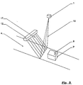
- Figure 4 shows schematically a part of a parcel distribution system consisting of a Conveyor belt 4, a height measuring device 14 and a frame 13 on which the camera 1 and a lighting device 12 are attached.
- the packages are on the conveyor belt 4 hung up and transported in the direction of arrow A. They pass through a height measuring device 14, which can consist of a large number of parallel light barriers, for example.
- the autofocus system of the line scan camera 1 reacts and sets the Distance of the image sensor 6 so that the plane of the upper surface 9 of the package P sharp is mapped.
- the light barrier height measuring device for example, one optical triangulation, an ultrasound, radar or infrared measurement can take place around the Measure distance between package surface 9 and camera optics 5.
- the lighting device 12 consists of an essentially linear light source or a linear array of spotlights with a focusing device, which directs the light from the light source onto the surface of the packets P, which is captured by the line scan camera will.
- the lighting device 12 can be a somewhat smaller distance from the Surface of the conveyor belt 4 and the surface of the objects P as the camera 1 to have.
- a lighting device with the desired intensity distribution can be realized by two spotlights arranged at a suitable distance, whose Focusing device gives the emitters a bell-shaped intensity distribution along A parallel to the line connecting the two emitters adds up their intensities a constant value at a constant distance from this line.
- the axis of the radiator and its connecting line spanned level 17 is one level maximum Illumination intensity
- the two spotlights shown in FIG. 4 can be adjusted separately in order to achieve the to be able to set optimal lighting.
- the plane 17 intersects the maximum Illumination intensity the conveyor belt 4 along a line 22 which, in the transport direction of the Seen band, lies behind the section line 21 of the imaging plane 10 with the conveyor belt 4
- the exact and desirable orientation of these levels 10, 17 has already been mentioned and will be explained in detail in connection with Figures 5 and 6.
- the Illumination device 12 can consist, for example, of a series of spotlights, whose light is focused and directed downwards onto the conveyor belt 4. Where the above defined plane 17 intersects a surface 9 of an object, so is the lighting intensity strongest on this surface. Along a line parallel to the series of For spotlights, the lighting intensity is constant, even with two directed in parallel Spotlights that have a bell-shaped intensity distribution around a central axis and arranged at a distance from one another which is matched to this intensity distribution the above conditions for lighting can be met in a good approximation.
- the level 17 is aligned so that the intersection of the level 17 with the level of Conveyor belt 4 as precisely as possible along the imaging line captured by the camera 1 runs, i.e. the intersection line mentioned coincides with the intersection line between imaging plane 10 and level 17 or between imaging level 10 and conveyor belt surface together.
- the intersection line 22 falls between the surface 9 of the package and the plane 17 does not coincide with the section line 21 of the surface 9 and the imaging plane 10.
- the package surface 9 is thus exposed to less light than along the parallel cutting line 22 between the package surface 9 and the plane 17 maximum Intensity of lighting.
- the higher the packet P the greater the distance between the Line of maximum lighting intensity and the imaging line 21 and accordingly lets also the intensity of the illumination of the imaging line 21 with increasing height of the packets after.
- the distance between the package surface and the camera 1 is decreasing the light-sensitive sensor 6 of the line scan camera correspondingly more light from the imaging line than at a larger distance from an imaging line (illuminated with the same intensity).
- the decrease in the intensity of the lighting in higher packages is therefore the shorter Distance to the camera is at least partially compensated and it is ultimately just a question of Inclination of level 17 and the appropriately chosen focus and intensity distribution relative to level 17 when you see the changes in brightness of the imaging line at different Package height wants to vary so that the apparent brightness of the imaging line for the line scan camera remains unchanged, i.e. the camera's light sensors per pixel and unit of time identical surfaces always absorb essentially the same amount of light quanta, when the distance of the surface from the camera is changed in the intended area. Different aperture times of the camera can also be used for different Resolutions along the transport direction are taken into account.
- This mode of operation of the lighting according to the invention is again schematic in FIG reproduced, the intensity distributions of the lighting are also shown in such a way that they each pass through the imaging line on the package surface.
- the lighting intensity of the package surface increases with increasing Distance of the package surface from the lighting device 12 decreases, but at least for the area of the imaging line 21 is overcompensated in the present case in that at a greater distance from the package surface, as in the case of package surface 2, the imaging line closer to the maximum intensity of the lighting.
- this type of lighting method and the corresponding lighting device are independent of the other features of the present invention and also Can be used for completely different purposes where it is not on detection of information arrives on potentially large surfaces, for example automatic ones Distribution and sorting systems and optical detection devices of all kinds.
Abstract
Description
Die vorliegende Erfindung betrifft ein Verfahren und eine Vorrichtung zur Erfassung von auf potentiell großflächigen Gegenständen aufgebrachten, optisch erfaßbaren Informationen. Bei dem entsprechenden Verfahren wird ein Gegenstand mit einer potentiell großen Oberfläche in das Sichtfeld einer Videokamera gebracht und die im Sichtfeld der Videokamera erkennbaren Informationen werden zwecks Identifikation und/oder Zuordnung des Gegenstandes in ein Rechnersystem eingegeben. Die entsprechende Vorrichtung weist daher eine Videokamera und eine Eingabevorrichtung für die Informationen aus dem von der Videokamera erfaßten Gesichtsfeld auf. Dabei beanspruchen die optisch erfaßbaren Informationen auf der Oberfläche eines Gegenstandes oft nur einen kleinen Teil von dessen Fläche, insbesondere dann, wenn es sich um einen sehr großflächigen Gegenstand handelt. Im Falle der vorliegenden Erfindung ist es nicht zwingend, daß ein Gegenstand, von dessen Oberfläche Informationen erfaßt werden sollen, tatsächlich eine große (im allgemeinen ebene) Oberfläche aufweist, sondern diese Fläche kann im Einzelfall auch relativ klein sein, wobei jedoch das Verfahren und die Vorrichtung dafür ausgelegt sind, die Informationen im wesentlichen unbhängig von der Größe der Fläche und selbst dann gut und genau zu erfassen, wenn der betreffende Gegenstand eine sehr große Oberfläche aufweist, während die entsprechenden Informationen möglicherweise nur einen kleinen Teil dieser Oberfläche beanspruchen. Mit "Oberfläche" wird dabei im Sinne der vorliegenden Beschreibung im allgemeinen die der Kamera direkt zugewandte Fläche eines Gegenstandes bezeichnet, deren Abstand von der Kamera innerhalb der Schärfentiefe der Kameraoptik varieren kann und die gegebenenfalls auch uneben, zum Beispiel mehr oder weniger gewellt, sein kann.The present invention relates to a method and an apparatus for detecting potentially large-area objects, optically detectable information. In which corresponding method, an object with a potentially large surface area is inserted into the Brought field of view of a video camera and those recognizable in the field of view of the video camera Information is integrated into one for the purpose of identification and / or assignment of the object Computer system entered. The corresponding device therefore has a video camera and an input device for the information from that captured by the video camera Field of view. The optically detectable information on the surface is used of an object often only a small part of its area, especially if it is is a very large object. In the case of the present invention, it is not necessarily that an object from whose surface information is to be acquired actually has a large (generally flat) surface, but this area can may also be relatively small in individual cases, however, the method and the device therefor are designed, the information is essentially independent of the size of the area and itself then to grasp well and precisely if the object in question has a very large surface area while the relevant information may only be a small part of it Claim surface. "Surface" is used in the sense of the present description generally refers to the surface of an object directly facing the camera, the Distance from the camera can vary within the depth of field of the camera optics and the possibly uneven, for example more or less wavy.
Ein typisches Beispiel für entsprechende Verfahren und Vorrichtungen liefert eine Paketverteilanlage. In einer Paketverteilanlage werden Pakete der unterschiedlichsten Größe auf Transportbändern angeliefert, wobei die Transportbänder im allgemeinen dafür ausgelegt sind, Pakete bis zu einer vorgegebenen Maximalgröße aufzunehmen, ohne daß die Pakete notwendigerweise alle die Maximalgröße haben müssen. Die vorliegende Erfindung soll jedoch nicht auf Paketverteilanlagen beschränkt sein, sondern kann auch in Produktionsprozessen für Sortier- und Verteilanlagen oderdergleichen verwendetwerden. Die folgende Beschreibung nimmt jedoch der besseren Verständlichkeit wegen vor allem auf das konkrete Beispiel einer Paketverteilanlage Bezug. Im Stand der Technik sind Verfahren und Vorrichtungen der vorstehend beschriebenen Art nur mit ganz bestimmten Einschränkungen bekannt Herkömmliche Videokameras sind nämlich nicht in der Lage, großflächige Gegenstände mit einer genügenden Auflösung vollständig zu erfassen, um die gegebenenfalls nur auf einem sehr kleinen Bereich des großflächigen Gegenstandes aufgebrachten Informationen noch hinreichend deutlich, d.h. mit der notwendigen Auflösung, erkennen zu können.A parcel distribution system provides a typical example of corresponding methods and devices. In a parcel distribution system, parcels of various sizes are opened Delivered conveyor belts, the conveyor belts are generally designed to Packets up to a predetermined maximum size without the packets necessarily all have to be the maximum size. However, the present invention is intended not be limited to parcel distribution systems, but can also be used in production processes for Sorting and distribution systems or the like are used. The following description takes however, for the sake of better comprehensibility, mainly due to the specific example of Parcel distribution system cover. In the prior art, methods and devices are as described above described type known only with certain restrictions conventional This is because video cameras are not able to handle large objects with sufficient Resolution to be recorded completely in order to possibly only cover a very small area of the information applied to large objects is still sufficiently clear, i.e. with the necessary resolution to be able to recognize.
Soweit daher in entsprechenden Anlagen überhaupt Videokameras Verwendung gefunden haben, war dies bisher auf Anwendungsfälle beschränkt, in denen sichergestellt war, daß der Oberflächenausschnitt eines Gegenstandes, der die zur Identifikation und Zuordnung des Gegenstandes notwendigen Informationen enthielt, immer einen vorgegebenes Sichtfeld durchlief, welches im Vergleich zu der der Kamera zugewandten, gesamten Oberfläche des Gegenstandes relativ klein sein konnte. Konkret wurde also das Verfahren nur für Standardpakete angewendet, welche einen Adressaufkleber oder dergleichen immer im selben Bereich des Paketes hatten, wobei die Pakete dementsprechend auch immer in derselben Ausrichtung und Position auf einem Transportband oder dergleichen angeordnet werden mußten. Ein solches Verfahren ist noch brauchbar zum Beispiel für Versandhäuser, welche Pakete in Standardgrößen und mit einer standardisierten Aufmachung versenden, so daß Adressaufkleber tatsächlich immer dieselbe Größe und Anordnung auf einem Paket haben. Dabei können außerdem jeweils Pakete einer einzelnen Größe auf je einem Förderband angeordnet werden, so daß die Kamera auch immer denselben Abstand zur Oberfläche des Paketes hat. Diese herkömmlichen Verfahren sind jedoch nicht mehr anwendbar für die Post oder andere kommerzielle Kurierdienste, die Pakete von Jedermann oder jedenfalls unterschiedlichen Kunden entgegennehmen und an eine Zieladresse befördern. Derartige Pakete sind allenfalls insoweit standardisiert, als sie eine vorgegebene Maximalgröße nicht überschreiten dürfen. Ein verbreiteter Standard ist zum Beispiel eine maximale Höhe und Breite von 900 mm, wobei die Länge unter Umständen dieses Maß noch übersteigen kann. Im allgemeinen haben derartige Pakete Quaderform und eine ebene Oberfläche, auf welcher Adressinformationen, Informationen über die Handhabung des Paketes oder den Inhalt (Bruchgefahr, Ausrichtung nach oben bei Transport ader Lagerung) und die Art der Beförderung (zum Beispiel Expressgut) enthalten sind. Außerdem können auch noch Angaben über den Absender auf der Paketoberfläche aufgebracht sein. Weder die Größe noch die Anordnung all dieser Informationen auf der Paketoberfläche sind eindeutig festgelegt. Ein Teil dieser Informationen oder auch Zusatzinformationen können außerdem in Form eines sogenannten Strichcodes auf der Paketoberfläche aufgebracht sein.As far as video cameras have been used in corresponding systems, was previously limited to use cases in which it was ensured that the Surface section of an object that is used to identify and assign the Always contained a necessary field of view, which in comparison to the entire surface of the object facing the camera could be relatively small. Specifically, the procedure was only used for standard packages, which always had an address label or the like in the same area of the package, accordingly, the packages always in the same orientation and position on one Conveyor belt or the like had to be arranged. Such a process is still in progress usable for mail order companies, for example, which parcels in standard sizes and with one standardized packaging so that address labels are actually always the same Have size and arrangement on one package. Packets of one can also be used individual size can be arranged on a conveyor belt, so that the camera always has the same distance from the surface of the package. However, these conventional methods are no longer applicable to the post office or other commercial courier companies that ship packages from Accept everyone or at least different customers and to a destination address promote. Such packages are at most standardized to the extent that they are a predetermined one Must not exceed the maximum size. A common standard is, for example maximum height and width of 900 mm, the length may still be this dimension can exceed. In general, such packages have a cuboid shape and a flat shape Interface on which address information, information about the handling of the package or the content (risk of breakage, upward orientation during transport or storage) and Art transportation (for example express goods) are included. You can also add information be applied to the parcel surface via the sender. Neither the size nor the The arrangement of all this information on the package surface is clearly defined. A part this information or additional information can also be in the form of a so-called bar codes can be applied to the package surface.
Herkömmlich wurden für derartige Pakete Verfahren und Verteilanlagen benutzt, bei welchen eine neben einem entsprechenden Förderband stehende Person diese Pakete unmittelbar in Augenschein nahm und die auf dem Paket aufgebrachten Informationen unmittelbar in ein neben dem Förderband stehendes Terminal oder dergleichen eingab, wobei zusätzlich noch ein Strichcodeleser Verwendung finden konnte.Processes and distribution systems, in which one person standing next to a corresponding conveyor belt these packages directly in Inspected and the information attached to the package immediately in an adjacent entered the conveyor standing terminal or the like, with an additional Bar code reader could be used.
Ausgehend von diesem Stand der Technik liegt der vorliegenden Erfindung die Aufgabe zugrunde, ein Verfahren und eine Vorrichtung der eingangs genannten Art zu schaffen, welche auch in Situationen, in welchen auf potentiell großen Oberflächen die in eine Rechnersystem zu übernehmenden Informationen in beliebigen Bereichen der Oberfläche angeordnet sein können, eine Fernerfassung und vorzugsweise sogar eine automatische Erfassung dieser Informationen ermöglichen.Starting from this prior art, the present invention is based on the object to create a method and a device of the type mentioned, which also in Situations in which on potentially large surfaces the in a computer system too receiving information can be arranged in any areas of the surface, a remote acquisition and preferably even an automatic acquisition of this information enable.
Hinsichtlich des eingangs definierten Verfahrens wird diese Aufgabe dadurch gelöst, daß als Videokamera eine hochauflösende Zeilenkamera verwendet wird, deren Zeilenlänge im Objektabstand die maximale Abmessunge eines Gegenstandes in dieser Richtung vollständig abdeckt, daß der Gegenstand im wesentlichen quer zur Längserstreckung der Abbildungszeile mit im wesentlichen kontinuierlicher Geschwindigkeit durch das Abbildungsfenster bzw. die Abbildungsebene der Zeilenkamera hindurchbewegt wird und daß die Bilderfassungsfrequenz und die Vorschubgeschwindigkeit der Gegenstände derart aufeinander abgestimmt werden, daß die Auflösung, d.h. der Abstand aufeinanderfolgender Abbildungszeilen, zumindest eine vergleichbare Größenordnung hat wie die Auflösung Innerhalb einer Abbildungszeile. Je nach Anforderung könnte die Auflösung zwischen den Zeilen durchaus um einen Faktor zwischen 1 und 10 von der Auflösung innerhalb der Zeilen abweichen, bevorzugt ist jedoch eine Ausgestaltung des erfindungsgemäßen Verfahrens, bei welcher die Auflösung in beiden Richtungen in etwa gleich ist. Dabei ist insbesondere zu berücksichtigen, daß auch die Ausrichtung der Informationen auf der Oberfläche des Gegenstandes nicht festgelegt ist, so daß eine gewisse, minimale Auflösung in jeder Richtung vorhanden sein muß. Aufgrund der Verwendung einer hochauflösenden Zeilenkamera ist es möglich, auch auf sehr großflächigen Gegenständen, die zum Beispiel eine Fläche von 900 x 1000 mm2 haben, einen Ausschnitt von nur 100 x 100 mm2 in genügender Auflösung darzustellen, um auf dieser Fläche aufgebrachte Informationen, zum Beispiel Adressbeschriftungen in normaler oder auch in feiner Schriftgröße, ablesen und eingeben zu können.With regard to the method defined at the outset, this object is achieved in that a high-resolution line camera is used as the video camera, the line length of which in the object distance completely covers the maximum dimensions of an object in this direction, that the object essentially transversely to the longitudinal extension of the image line at an essentially continuous speed is moved through the imaging window or the imaging plane of the line camera and that the image acquisition frequency and the feed speed of the objects are coordinated with one another in such a way that the resolution, that is to say the spacing between successive imaging lines, has at least a comparable magnitude as the resolution within an imaging line. Depending on the requirements, the resolution between the lines could deviate by a factor between 1 and 10 from the resolution within the lines, but an embodiment of the method according to the invention is preferred in which the resolution is approximately the same in both directions. It should be noted in particular that the orientation of the information on the surface of the object is not fixed either, so that there must be a certain, minimal resolution in each direction. Due to the use of a high-resolution line scan camera, it is possible to display a section of only 100 x 100 mm 2 in sufficient resolution, even on very large objects that have an area of 900 x 1000 mm 2 , for example, in order to display information applied to this area, For example, you can read and enter address labels in normal or fine font size.
Die Begriffe "ablesen" und "eingeben" umfassen dabei sowohl das Ablesen und Eingeben durch eine Person, als auch ein maschinelles, automatisches Ablesen, welches gegebenenfalls nur durch eine Person kontrolliert und bestätigt wird.The terms "read" and "enter" include both reading and entering a person, as well as a mechanical, automatic reading, which if necessary only is checked and confirmed by one person.
Mit Abildungszeile oder Abbildungslinie ist im Sinne der vorliegenden Beschreibung eine Linie bzw. Reihe von Punkten bzw. kleinen Flächen aufder Oberfläche des betreffenden Gegenstandes gemeint die ein monentanes Gesichtsfeld der Zeilenkamera bilden, wogegen der Begriff Bildzeile die korrespondierende Reihe von Bildpunkten bzw. -Flächen auf dem Bild des Gegenstandes bezeichnet, die auf einem Terminal oder einem anderen Darstellungsmedium wiedergegeben oder in einem Speicher in Form digitalisierter Daten abgelegt ist.In the sense of the present description, there is a line with an illustration line or an illustration line or series of points or small areas on the surface of the object in question meant the line of sight of the line scan camera, whereas the term image line the corresponding row of pixels or areas on the image of the object referred to or reproduced on a terminal or other display medium is stored in a memory in the form of digitized data.
Bevorzugt ist die Verwendung einer Zeilenkamera mit mehr als 1000, vorzugsweise mehr als 3000 und insbesondere etwa 5000 bis 7000 Bildpunkten entlang der Zeile. Wie man leicht errechnen kann, ergeben 5000 Bildpunkte entlang einer Abbildungszeile von zum Beispiel 1000 mm eine Auflösung von 0,2 mm. Dies reicht für herkömmliche Beschriftungen bei weitem aus und der Fachmann erkennt, daß ein entsprechendes Verfahren auch mit einer Auflösung von zum Beispiel 2000 Bildpunkten auf 1 Meter bei hinreichend großer Schrift noch mit akzeptabler Genauigkeit zu betreiben wäre. Bevorzugt ist jedoch eine maximale Zeilenauflösung von 7000 Punkten.It is preferred to use a line scan camera with more than 1000, preferably more than 3000 and especially about 5000 to 7000 pixels along the line. How to calculate easily , 5000 pixels along an image line of, for example, 1000 mm result in a 0.2 mm resolution. This is by far sufficient for conventional inscriptions A person skilled in the art will recognize that a corresponding method also has a resolution of, for example 2000 pixels per 1 meter with a sufficiently large font still with acceptable accuracy would operate. However, a maximum line resolution of 7000 points is preferred.
Der Objektabstand sollte vorzugsweise mehr als das Zweifache und insbesondere mehr als das Dreifache der maximalen Breite der zu erfassenden Gegenstände betragen. Dabei ist dieser Objektabstand entlang der - nicht notwendigerweise gerade verlaufenden - optischen Strahlenachse des Systems zu messen. Dieser Strahlengang kann dabei auch durch einen oder mehrere Spiegel, eventuell auch durch Lichtleiter oder dergleichen umgelenkt werden, wenn dies zum Beispiel zur Begrenzung der Bauhöhe des Gesamtsystems notwendig oder zweckmäßig erscheint Der relativ große Objektabstand stellt dabei eine hinreichende Schärfentiefe der Kameraoptik sicher, die auf jeden Fall den Bereich umfaßt, innerhalb dessen der Abstand der Objektoberfläche von der Kameraoptik während des Durchlaufs durch die Abbildungsebene variieren kann. Dabei ist insbesondere auch zu berücksichtigen, daß wegen der potentiell relativ großen Fläche und der maximalen Länge einer Abbildungszeile von zum Beispiel 1 m die zentralen Abbildungspunkte dieser Zeile der Kameraoptik deutlich näher liegen als die Abbildungspunkte an den Enden der Zeile (wenn die Kamera symmetrisch bezüglich des Abbildungsmittelpunktes angeordnet ist). Diese relativen Unterschiede werden aufgrund des relativ großen Objektabstandes der Kamera entsprechend vermindert. Außerdem ist zu beachten, daß die einzelnen Gegenstände eine sehr unterschiedliche Höhe haben können. Im Falle der als Beispiel betrachteten Paketverteilungsanlage können die Höhenunterschiede zwischen verschiedenen Paketen zum Beispiel bis zu 800 mm betragen. Um sowohl den niedrigsten als auch den höchsten Gegenstand mit hinreichender Schärfe erfassen zu können, ist zum einen eine automatische Nachfokussierung vorgesehen, wobei jedoch auch hier der große Objektabstand der Zeilenkamera die Fokussierung über den entsprechend der Höhe der Gegenstände variierenden Abstandsbereich ohne weiteres ermöglichtThe object distance should preferably be more than twice and in particular more than that Three times the maximum width of the objects to be detected. Here is this Object distance along the - not necessarily straight - optical beam axis of the system. This beam path can also be through one or more Mirrors, possibly also deflected by light guides or the like if this leads to Example for limiting the overall height of the overall system appears necessary or expedient The relatively large object distance represents a sufficient depth of field for the camera optics sure, which definitely encompasses the area within which the distance of the object surface can vary from the camera optics during the passage through the imaging plane. Here In particular, it should also be borne in mind that because of the potentially relatively large area and the maximum length of an image line of, for example, 1 m the central image points this line of camera optics are significantly closer than the imaging points at the ends of the Line (if the camera is arranged symmetrically with respect to the center of the image). These relative differences are due to the relatively large object distance of the camera reduced accordingly. It should also be noted that the individual items are very can have different heights. In the case of the parcel distribution system considered as an example For example, the height differences between different packages can be up to 800 mm. To both the lowest and the highest item with sufficient To be able to detect sharpness, automatic refocusing is provided on the one hand, however, here too the large object distance of the line camera focuses on the distance range varying according to the height of the objects easily possible
Bevorzugt ist dabei eine Variante des erfindungsgemäßen Verfahrens, wonach zur automatischen Fokussierung der Bildsensor in der Zeilenkamera relativ zur Kameraoptik verschoben wird. Konkret kann die Kameraoptik bzw. eine Abbildungslinse festgehalten werden und der Abstand des Zeilensensors in der Zeilenkamera von dieser Linse oder Optik wird entsprechend dem Abstand der Objektoberfläche variiert. Dabei reicht ein Hub in der Größenordnung von 1 - 2 mm aus, um bei einem Objektabstand von mindestens 3 m Höhendifferenzen von 800 mm in der Bildschärfe auszugleichen.Preferred is a variant of the method according to the invention, according to which the automatic Focusing of the image sensor in the line scan camera is shifted relative to the camera optics. Specifically, the camera optics or an imaging lens can be recorded and the distance of the line sensor in the line camera of this lens or optics is corresponding to that Distance of the object surface varies. A stroke of the order of 1 - 2 mm is sufficient in order to achieve an object distance of at least 3 m height differences of 800 mm in the Balance sharpness.
Eine wichtige Rolle bei einer genauen Bilderfassung spielt im Rahmen der vorliegenden Erfindung auch eine geeignet ausgestaltete und angepaßte Beleuchtung. Dabei kommt es der vorliegenden Erfindung zugute, daß sie eine Zeilenkamera verwendet, die jeweils nur einen sehr schmalen Streifen aus der Oberfläche eines Gegenstandes erfaßt, wobei das Gesamtbild der Oberfläche des Gegenstandes aus einer Vielzahl aufeinanderfolgender, paralleler Streifen zusammengesetzt wird, die sich aus zeitlich nacheinander aufgenommenen Bildzeilen ergeben, wenn der Gegenstand durch die Abbildungsebene hindurchbewegt wird, während die Kamera mit einer vorgegebenen Frequenz nacheinander die einzelnen Zeilen aufnimmt und die Bilddaten entsprechend zwischenspeichert. Im Gegensatz zu herkömmlichen Verfahren muß dann nicht die gesamte Oberfläche des Gegenstandes bzw. die gesamte, Informationen enthaltende Teilfläche desselben gleichmäßig ausgeleuchtetwerden, sondern es reicht aus, wenn die Gegenstandsoberfläche entlang der schmalen Zeile homogen ausgeleuchtet ist, die sich als Schnittlinie der Gegenstandsoberfläche und der Abbildungsebene ergibt Die Abbildungsebene wird dabei aufgespannt durch die optische Achse der Kamera und die Zeilenrichtung.An important role in accurate image acquisition plays in the context of the present invention also a suitably designed and adapted lighting. It is the present Invention benefited that it uses a line scan camera, each of which is only a very narrow one Strips captured from the surface of an object, the overall image of the surface of the object composed of a plurality of successive, parallel strips , which result from image lines recorded one after the other when the Object is moved through the imaging plane while the camera with a predetermined frequency consecutively records the individual lines and the image data cached accordingly. In contrast to conventional methods, the entire surface of the object or the entire partial area containing information of the same are illuminated uniformly, but it is sufficient if the object surface is homogeneously illuminated along the narrow line, which is the intersection of the The surface of the object and the level of the image results in the level of the image spanned by the optical axis of the camera and the line direction.
Erfindungsgemäß ist vorgesehen, daß das Licht der Beleuchtungseinrichtung derart fokussiert wird, daß eine Ebene maximaler Intensität die Abbildungsebene nahe der Oberfläche der Vorschubeinrichtung bzw. im Bereich der Oberfläche eines Gegenstandes mit maximalem Abstand zu Kamera schneidet, d.h. die Oberflächen der niedrigsten Gegenstände, die den weitesten Abstand zur Kamera haben, werden in der Abbildungsebene und damit entlang der Abbildungslinie mit maximaler Intensität beleuchtet. Bei entsprechend höheren und näher an der Kamera liegenden Oberflächen nimmt die Beleuchtungsintensität in der Abbildungsebene entsprechend ab, was jedoch durch den kürzeren Abstand der Kamera zu der Gegenstandsoberfläche kompensiert wird, so daß die Abbildungslinie im wesentlichen die gleiche scheinbare Helligkeit hat, wie im Falle der weiter entfernten, intensiver beleuchteten Abbildungslinie.It is provided according to the invention that the light of the lighting device focuses in this way becomes that a plane of maximum intensity the imaging plane near the surface of the Feed device or in the area of the surface of an object with a maximum distance cuts to camera, i.e. the surfaces of the lowest objects, the widest Distance to the camera are in the imaging plane and thus along the imaging line illuminated with maximum intensity. At correspondingly higher and closer to the camera lying surfaces takes the lighting intensity in the image plane accordingly from, however, due to the shorter distance between the camera and the object surface is compensated so that the imaging line has essentially the same apparent brightness, as in the case of the more distant, more intensely illuminated image line.
Ein weiterer, für die Beleuchtung zu berücksichtigender Aspekt liegt gegebenenfalls in der Änderung der Abtastfrequenz, die vorzugsweise mit der Höhe der Gegenstandsoberfläche, in der Weise zunimmt, daß sich in Transportrichtung, also senkrecht zur Abbildungszeile bzw Bildzeile, dieselbe Auflösung ergibt wie innerhalb der Zeile. Allerdings gilt dies nur, wenn sich bei einer näher zur Kamera liegenden Gegenstandsoberfläche die Auflösung in Zellenrichtung ändert, d. h., wenn für eine weiter entfernt liegende Fläche nicht die volle Zeilenlänge des Bildsensors und damit die volle Zeilenauflösung genutzt werden kann, so daß näher gelegene Flächen mit einer höheren Auflösung erfasst werden. Dies trifft immer dann zu, wenn die Kamera nicht über eine Zoom-Optik verfügt, also mit konstanter Brennweite arbeitet. Diese Erhöhung der Abtastfrequenz reduziert ebenfalls die scheinbare Helligkeit des Bildes näher liegender Flächen, kompensiert aber nicht vollständig die Helligkeitszunahme durch die entsprechende Verringerung des Abstandes zur Lichtquelle, wenn deren Beleuchtungsintensität nicht in der vorgesehenen Weise variieren würde. Allerdings wird der erforderliche Intensitätsverlauf der Beleuchtung, gesehen in Richtung senkrecht zur Ebene maximaler Intensität, etwas abgeflachtAnother aspect to be taken into account for the lighting lies in the Change in sampling frequency, preferably with the height of the object surface, in the Way increases that in the direction of transport, i.e. perpendicular to the image line or image line, gives the same resolution as within the line. However, this only applies if there is a Object surface closer to the camera changes the resolution in the cell direction, d. that is, if for an area further away the full line length of the image sensor and so that the full line resolution can be used, so that closer areas with a higher resolution. This is always the case if the camera does not have one Zoom optics has a constant focal length. This increase in sampling frequency also reduces the apparent brightness of the image of closer surfaces, but compensates not completely increase the brightness by reducing the distance accordingly to the light source if its lighting intensity does not vary in the intended way would. However, the required intensity curve of the lighting is seen in the direction perpendicular to the plane of maximum intensity, somewhat flattened
Die Ebene der maximalen Intensität der Beleuchtung hat dabei vorzugsweise einen Neigungswinkel von mindestens 0°, vorzugsweise von etwa 10°bis 30° und höchstens etwa 50° relativ zu der Abbildungsebene, wobei die Abbildungsebene vorzugsweise in die gleiche Richtung wie die erwähnte Beleuchtungsebene gegenüber einer Senkrechten zu der Transportoberfläche geneigt ist. Die Abbildungsebene kann gegenüber einer Senkrechten zur Transportebene zum Beispiel um 20° geneigt sein, wobei die Schnittlinie zwischen Abbildungsebene und Transportebene im allgemeinen senkrecht zur Transportrichtung verläuft. Unabhängig von der Neigung kann allerdings die Abbildungsebene auch um eine Senkrechte zur Transportebene noch um einen kleinen Winkel verdreht sein, so daß die erwähnte Schnittlinie nicht mehr senkrecht zur Transportrichtung verläuft.The level of the maximum intensity of the lighting preferably has an angle of inclination from at least 0 °, preferably from about 10 ° to 30 ° and at most about 50 ° relative to the imaging plane, the imaging plane preferably in the same direction as that mentioned illumination plane inclined to a perpendicular to the transport surface is. The mapping level can be compared to a perpendicular to the transport level, for example be inclined by 20 °, the intersection between the imaging plane and the transport plane in is generally perpendicular to the direction of transport. Regardless of the inclination can however, the mapping level is also one perpendicular to the transport level small angle can be twisted so that the cut line mentioned is no longer perpendicular to Direction of transport runs.
Die gleichzeitige Neigung von Abbildungsebene und Beleuchtungsebene dient vor allem der Verhinderung von durch die Kamera erfassten Reflexen, wie sie bei spiegelnden Flächen, wie zum Beispiel Folien und insbesondere auch leicht gewellten Folien auf der Gegenstandsoberfläche auftreten könnten. Derartige Reflexe werden bei der bevorzugten, geneigten Anordnung nicht bzw. in weniger störender Form durch die Kamera erfasst.The simultaneous inclination of the image plane and the illumination plane serves above all Prevention of reflections captured by the camera, such as with reflecting surfaces, such as Example foils and in particular also slightly corrugated foils occur on the object surface could. Such reflections are not in the preferred inclined arrangement or captured in less disturbing form by the camera.
Bevorzugt ist eine Ausgestaltung des Verfahrens, bei welchem mehrere Zeilenkameras an bzw. über mehreren Vorschubeinrichtungen die Oberflächen von darauf transportierten Gegenständen erfassen, wobei die Zeilenkameras über eine Speichereinrichtung und ein Netzwerk mit einem Leitrechner sowie mit Eingabeterminals verbunden sind, an welchen gegebenenfalls die abgebildeten Gegenstandsoberflächen wiedergegeben und die daraus zu entnehmenden Informationen eingegeben werden.An embodiment of the method is preferred in which a plurality of line scan cameras are attached to or the surfaces of objects transported on it via several feed devices capture, the line cameras via a storage device and a network with a Main computer and connected to input terminals, where the reproduced object surfaces and the ones to be extracted from them Information can be entered.
Insbesondere ist die Verwendung des erfindungsgemäßen Verfahrens für eine Paketverteilanlage vorgesehen.In particular, the method according to the invention is used for a parcel distribution system intended.
Hinsichtlich der eingangs genannten Vorrichtung wird die der Erfindung zugrunde liegende Aufgabe dadurch gelöst, daß als Videokamera eine hochauflösende Zeilenkamera vorgesehen ist, wobei die Kameraoptik so ausgelegt bzw. angeordnet ist, daß die maximale Breite eines Gegenstandes, gesehen in Richtung der Zeile, vollständig erfaßt wird, und daß eine Vorschubeinrichtung vorgesehen ist, welche den zu erfassenden Gegenstand quer zur Zeilenrichtung und durch die Abbildungsebene der Zeilenkamera hindurch mit im wesentlichen gleichförmiger Geschwindigkeit transportiert.With regard to the device mentioned at the beginning, the one on which the invention is based Object achieved in that a high-resolution line camera is provided as a video camera is, the camera optics is designed or arranged so that the maximum width of a Object, seen in the direction of the line, is completely detected, and that a feed device is provided which is the object to be detected transversely to the line direction and through the imaging plane of the line scan camera with a substantially more uniform one Speed transported.
Die Transporteinrichtung ist vorzugsweise ein Förderband, welches die Gegenstände mindestens im Bereich der Zeilenkamera weitgehend erschütterungsfrei transportiert.The transport device is preferably a conveyor belt which at least the objects transported in the area of the line scan camera largely free of vibrations.
Dabei ist die Vorrichtung vorzugsweise so ausgestaltet, daß die Bildwiederholfrequenz der Zeilenkamera und/oder die Transportgeschwindigkeit der Vorschubeinrichtung aufeinander abgestimmt steuerbar sind. Die Zeilenwiederholfrequenz der Zellenkamera ergibt in Verbindung mit der Transportgeschwindigkeit der Vorschubeinrichtung den Abstand aufeinanderfolgender Abbildungszeilen und damit auch den Abstand und die Auflösung der entsprechend darzustellenden Bildzeilen.The device is preferably designed so that the refresh rate of the Line scan camera and / or the transport speed of the feed device to one another are coordinated controllable. The line repetition frequency of the cell camera results in connection with the transport speed of the feed device the distance in succession Figure lines and thus also the distance and the resolution of those to be displayed accordingly Picture lines.
Wie bereits erwähnt, sollte die Zeilenkamera bei einer Erfassungsbreite von 900 mm einen Abstand von mehr als 2 m von der Oberfläche der abzubildenden Gegenstände haben. Vorzugsweise ist die Kamera etwa 4 m oberhalb der Oberfläche eines Transportbandes für die Gegenstände bzw in einem entsprechenden optischen Abstand angeordnet.As already mentioned, the line scan camera should have a detection width of 900 mm Have a distance of more than 2 m from the surface of the objects to be imaged. The camera is preferably about 4 m above the surface of a conveyor belt for the Objects or arranged at a corresponding optical distance.
Weiterhin ist vorgesehen, daß die Zeilenkamera so ausgerichtet ist, daß ihre oben definierte Abbildungsebene etwas in Richtung der Bandebene geneigt ausgerichet ist.It is also provided that the line scan camera is aligned so that it is defined above Imaging plane is aligned somewhat inclined in the direction of the band plane.
Die entsprechende Beleuchtungseinrichtung hat vorzugsweise eine Lichtquelle, deren Licht durch eine Fokussiereinrichtung derart gebündelt wird, daß eine Ebene (bei gleichbleibendem Abstand im wesentlichen konstanter) maximaler Lichtintensität sowohl zur Ebene der Vorschubeinrichtung als auch zu der Abbildungsebene der Zeilenkamera geneigt verläuft. Die Lichtquelle kann zum Beispiel durch eine Reihe, im einfachsten Fall zwei, entlang einer Linie (parallel zur Abbildungslinie) angeordnete Punktstrahler gebildet werden, die jeweils eine eigene Fokussiereinrichtung haben, so daß die überlappenden Lichtintensitäten der Reihe von Punktstrahlern der Lichtintensitätsverteilung einer homogenen, linienförmigen Lichtquelle relativ nahe kommen. Dabei wird durch die Fokussiereinrichtungen das Licht zu einer Seite hin gebündelt, wobei sich eine Ebene maximaler Lichtintensität ergibt, d.h. eine Ebene, welche einerseits von der linienförmigen Lichtquelle bzw. der Reihe von Punktstrahlern und andererseits von dem Richtungspfeil aufgespannt wird, in welcher die maximale Lichtintensität abgestrahlt wird. Die Beleuchtungseinrichtung bzw. deren Fokussiereinrichtung mit der Lichtquelle werden dann vorzugsweise so angeordnet, daß die erwähnte Ebene maximaler Lichtintensität die oben definierte Abbildungsebene in etwa auf der Oberfläche der Transporteinrichtung oder etwas darüber schneidet, nämlich in Höhe der Oberfläche eines auf der Transporteinrichtung transportierten Gegenstandes mit minimaler Höhe.The corresponding lighting device preferably has a light source whose light is transmitted through a focusing device is bundled in such a way that one plane (with constant distance essentially constant) maximum light intensity both to the level of the feed device and also inclined to the imaging plane of the line scan camera. The light source can be used for Example by a row, in the simplest case two, along a line (parallel to the image line) arranged spotlights are formed, each with its own focusing device have, so that the overlapping light intensities of the row of spotlights of the light intensity distribution come relatively close to a homogeneous, linear light source. Doing so through the focusing devices the light is bundled to one side, forming a plane maximum light intensity, i.e. a plane which is on the one hand from the linear Light source or the row of spotlights and on the other hand from the directional arrow is spanned in which the maximum light intensity is emitted. The lighting device or their focusing device with the light source are then preferably so arranged that the plane of maximum light intensity mentioned above the imaging plane cuts approximately on the surface of the transport device or somewhat above, namely at the level of the surface of an object transported on the transport device minimum height.
Konkret bedeutet dies, daß der Gegenstand durch die Beleuchtungseinrichtung derart beleuchtet ist, daß sich quer über den Gegenstand hinweglaufend eine Linie maximaler Beleuchtungsintensität ergibt, die zu beiden Seiten hin, d.h. zum vorausgehenden und zum nachlaufenden Ende des Gegenstandes hin, allmählich abnimmt. Dabei trifft bei den Gegenständen mit niedrigster Höhe, bei welchen also die abzubildende Oberfläche den maximalen Abstand zur Zeilenkamera hat, diese Linie maximaler Beleuchtungsintensität genau mit der von der Zeilenkamera erfaßten Abbildungszeile zusammen. Wegen der relativen Neigung der Ebene maximaler Lichtintensität relativ zur Abbildungsebene verläuft jedoch bei höheren Gegenständen die Abbildungszeile im Abstand zu der Linie maximaler Beleuchtungsintensität und parallel hierzu.Specifically, this means that the object is illuminated in this way by the lighting device is that a line of maximum lighting intensity runs across the object results on both sides, i.e. to the previous and the following End of the object, gradually decreasing. This affects the objects lowest height, at which the surface to be imaged is the maximum distance from Line scan camera has this line of maximum illumination intensity exactly with that of the Line camera captured picture line together. Because of the relative slope of the plane However, maximum light intensity relative to the imaging plane is for higher objects the image line at a distance from the line of maximum illumination intensity and parallel to it.
Dabei werden die Neigung der Ebene maximaler Lichtintensität und die Intensitätsverteilung zweckmäßigerweise so eingestellt, daß die geringere Beleuchtungsstärke der Abbildungszeilen bei höheren Gegenständen durch den kürzeren Kamerabstand derart kompensiert wird, daß sich für alle unterschiedlich hohen Gegenstände in etwa die gleiche scheinbare Helligkeit der Abbildungslinie bzw. -zeile ergibt. Der Winkel zwischen Abbildungsebene und Ebene maximaler Lichtintensität beträgt dabei vorzugsweise mindestens 10° und höchstens 50°, wobei dieser Neigungswinkel, ebenso wie die Neigung der Abbildungsebene in die gleiche Richtung, dazu beiträgt, daß keine störenden Reflexe von reflektierenden Oberflächenbereichen, wie zum Beispiel Abdeckfolien und dergleichen, in die Zeilenkamera gerichtet werden.The inclination of the plane of maximum light intensity and the intensity distribution expediently set so that the lower illuminance of the image lines with higher objects by the shorter camera distance is compensated in such a way that for all objects of different heights approximately the same apparent brightness Figure line or line results. The angle between the imaging plane and the maximum plane Light intensity is preferably at least 10 ° and at most 50 °, this being Inclination angle, as well as the inclination of the imaging plane in the same direction contributes to the absence of distracting reflections from reflective surface areas, such as Cover films and the like, are directed into the line scan camera.
In der bevorzugten Ausführungsform weist die erfindungsgemäße Vorrichtung mehrere getrennte Vorschubeinrichtungen auf, über welchen jeweils eine eigene Zeilenkamera mit angeschlossenem Sensorrechner angeordnet ist, der wiederum über ein schnelles Datennetzwerk mit mehreren Bearbeitungsterminals verbunden ist. Wegen der hohen Auflösung (bis zu 7000 Bildpunkte pro Zeile) und bei einer Zeilenwiederholfrequenz in der Größenordnung von bis zu 6000 Hertz fallen sehr große Datenmengen an, so daß in der bevorzugten Ausführungsform ein Datennetzwerk hoher Leistungsfähigkeit Verwendung findet, wie zum Beispiel ein 100 Mbit Ethernet mit einem sogenannten "Switching Hub" als Schaltknoten.In the preferred embodiment, the device according to the invention has several separate ones Feed devices on which each has its own line scan camera with a connected one Sensor computer is arranged, which in turn over a fast data network with several Processing terminals is connected. Because of the high resolution (up to 7000 pixels per Line) and fall at a line repetition frequency in the order of up to 6000 Hertz very large amounts of data, so in the preferred embodiment a data network high performance is used, such as a 100 Mbit Ethernet with a so-called "switching hub" as a switching node.
Mit einer solchen Vorrichtung ist es möglich, bei Verwendung meherer Zeilenkameras und mehrerer Terminals jeden der Sensorrechner der Zeilenkameras mit jedem beliebigen der Terminals zu verbinden. Vorzugsweise ist dabei die Anzahl der Eingabeterminals unabhängig von der Anzahl der Zeilenkameras. Dieses Merkmal ist deshalb vorgesehen, weil zum Beispiel die Erfassung und manuelle Eingabe der Informationssdaten durch einen Benutzer länger dauert als die Erfassung der Oberfläche eines Gegenstandes mit Hilfe der Zeilenkamera, so daß die Bilder der Zeilenkameras zwischengespeichert werden und jeweils von einem der Terminals zur Bearbeitung abgerufen werden. Die geringere Bildbearbeitungsgeschwindigkeit an den Terminals im Vergleich zur Erfassung der Bilder durch die Zeilenkameras wird dabei durch eine größere Anzahl von Terminals ausgeglichen. Dabei werden die einzelnen, erfaßten Bilder in der Reihenfolge ihrer Erfassung zwischengespeichert und in genau dieser Reihenfolge einzeln an die Terminals weitergegeben, und zwar in der Reihenfolge, wie sich die einzelnen Terminals als frei für die Bearbeitung eines neuen Bildes melden.With such a device it is possible, when using several line cameras and several terminals each of the sensor computers of the line scan cameras with any of the To connect terminals. The number of input terminals is preferably independent of the number of line scan cameras. This feature is provided because, for example, the Acquisition and manual entry of the information data by a user takes longer than the detection of the surface of an object using the line scan camera so that the images the line scan cameras are cached and each from one of the terminals to Processing can be called up. The lower image processing speed at the terminals in comparison to the capture of the images by the line scan cameras, this is due to a larger one Number of terminals balanced. The individual, captured images in the Order of their recording is cached and sent to the individual in exactly this order Terminals passed on, in the order in which the individual terminals turned out to be free report for editing a new image.
Umgekehrt kann jedoch die automatische Erfassung und Identifikation der Bildinformationen eventuell schneller ablaufen als das Erfassen der Gegenstandsoberflächen, so daß in einem solchen Fall die Zahl der Bearbeitungsterminals sogar kleiner sein könnte als die der Kameras und der zugehörigen Sensorrechner. Je nach Automatisationsgrad und Korrektur- und Überwachungserfordernissen durch Bedienpersonal kann das Verhältnis der Zahl von Terminals zu der der Kameras entsprechend variieren. Bei eindeutiger auutomatischer Identifizierbarkeit der Bildinformation kann die Auswertung direkt im Sensorrechner durchgeführt werden und die (Codier-)Terminals können dann entfallen.Conversely, however, the automatic acquisition and identification of the image information possibly run faster than the detection of the object surfaces, so that in one In such a case, the number of processing terminals could even be smaller than that of the cameras and the associated sensor computer. Depending on the degree of automation and correction and Monitoring requirements by operators can be the ratio of the number of terminals to that of the cameras vary accordingly. With clear automatic identifiability The image information can be evaluated directly in the sensor computer and the (Coding) terminals can then be omitted.
Dabei sind an den Terminals Einrichtungen vorgesehen, welche eine Ausschnittvergrößerung der zwischengespeicherten Bilder erlauben. Darüberhinaus ist es zweckmäßig, wenn die erfaßten Bilder von der Kameraelektronik oder aber von dem lokalen Sensorrechner komprimiert werden, so daß große homogene Bildflächen ohne Information nur geringen Speicherplatz beanspruchen, während von den kontrastreichen Flächen, welche die einzugebenden Informationen enthalten, entsprechend größere Datenmengen gespeichert werden.Facilities are provided at the terminals which enlarge the detail of the Allow cached images. In addition, it is useful if the detected Images from the camera electronics or from the local sensor computer are compressed, so that large, homogeneous image areas without information take up little storage space, while of the high-contrast areas that contain the information to be entered, correspondingly larger amounts of data are stored.
Jedes Terminal weist neben den Einrichtungen zum Herstellen einer Ausschnittvergrößerung vorzugsweise auch Einrichtungen auf, um das Bild oder einen Bildausschnitt zu drehen, vorzugsweise um 90°, um 180° oder um 270°, gegebenenfalls auch durch stufenweises Verdrehen um diskrete Winkelschritte.In addition to the facilities for producing a cut-out enlargement, each terminal shows preferably also means for rotating the image or an image detail, preferably by 90 °, by 180 ° or by 270 °, if necessary also by gradual twisting around discrete angular steps.
Außerdem hat jedes Terminal Einrichtungen für eine manuelle Eingabe von Informationsdaten, die von dem Bildschirm des Terminals abgelesen werden.In addition, each terminal has facilities for manual entry of information data, read from the terminal screen.
Besonders bevorzugt ist jedoch eine Ausgestaltung der erfindungsgemäßen Vorrichtung, bei welcher auch Einrichtungen zum automatischen Erfassen der Informationsdaten sowie zum Anzeigen dieser automatisch erfaßten Daten vorgesehen sind. Beispielsweise könnte die Vorrichtung neben einem Strich bzw. Barcodeleser auch einen Klarschriftleser aufweisen, wobei mit Hilfe eines geeigneten Programms die als digitalisiertes Bild im Rechner gespeicherte Oberfläche des Gegenstandes nach Oberflächenbereichen abgesucht wird, welche offenbar die gewünschten Informationen enthalten, die dann von einer Klarschriftlesesoftware in entsprechende digitale Symbole umgesetztwerden und wobei das Ergebnis anschließend aufdem Terminal, zum Beispiel in einem separaten Fenster auf einem Bildschirm, angezeigt wird. Eine Bedienperson braucht dann lediglich noch zu überprüfen, ob die maschinell erfaßten und in dem Fenster angezeigten Daten mit den gleichfalls auf dem Bildschirm abgebildeten sichtbaren Informationen auf der Paketoberfläche übereinstimmen und bestätigt dies gegebenenfalls oder nimmt mit Hilfe der Eingabeeinrichtung eine notwendige Korrektur vor. Auf diese Weise kann man zum Beispiel sicherstellen, daß beim maschinellen Ablesen nicht Absender und Empfängerverwechselt werden oder es können Lesefehler des Klarschriftlesers korrigiert werden. Bei eindeutiger Indentifikation kann die Visusalisierung gegebenenfalls auch entfallen.However, an embodiment of the device according to the invention is particularly preferred which also means for automatic recording of the information data and for Displays of this automatically collected data are provided. For example, the Device in addition to a bar or barcode reader also have a plain text reader, wherein with the help of a suitable program, the one saved as a digitized image in the computer Surface of the object is searched for surface areas, which apparently the contain the desired information, which is then converted into corresponding text by plain text software digital symbols are implemented and the result is then on the terminal to Example is displayed in a separate window on a screen. An operator then only needs to check whether the machine-recorded and in the window displayed data with the visible information also shown on the screen agree on the package surface and if necessary confirms this or takes with the help the input device before a necessary correction. This way you can, for example Make sure that the sender and recipient are not mistaken for machine reading or reading errors of the plain text reader can be corrected. With clear identification the visualization may also be omitted if necessary.
Weitere Vorteile, Merkmale und Anwendungsmöglichkeiten der vorliegenden Erfindung werden deutlich anhand der folgenden Beschreibung einer bevorzugten Ausführungsform und der dazugehörigen Figuren. Es zeigen:
Figur 1- eine Übersicht über ein Netzwerk zwischen Zeilenkameras, Eingabeterminals und einem Leitrechner, wie es zum Beispiel für eine Paketverteilungsanlage Verwendung finden kann,
Figur 2- die Draufsicht auf eine Paketoberfläche mit Informationen auf einem Teil dieser Fläche,
- Figur 3
- einen Schnitt durch eine schematische Ansicht einer Videokamera in der Abbildungsebene über einem Transportband,
Figur 4- eine perspektivische Ansicht einer Gegenstandserfassungseinrichtung,
- Figur 5
- in perspektivischer Darstellung die relative Anordnung von Kamera und Beleuchtungssystem und
Figur 6- ein Schema zur Erläuterung der unterschiedlichen Beleuchtungsintensitäten bei unterschiedlichen Oberflächenhöhen.
- Figure 1
- an overview of a network between line scan cameras, input terminals and a host computer, such as can be used for a parcel distribution system, for example,
- Figure 2
- the top view of a package surface with information on part of this surface,
- Figure 3
- 2 shows a section through a schematic view of a video camera in the imaging plane above a conveyor belt,
- Figure 4
- 1 shows a perspective view of an object detection device,
- Figure 5
- in perspective the relative arrangement of the camera and lighting system and
- Figure 6
- a scheme to explain the different lighting intensities at different surface heights.
Man erkennt in Figur 1 eine Reihe von Zeilenkameras, von denen konkret nur vier dargestellt sind.
Jede der Zeilenkameras enthält eine Sensoreinheit, eine Autofokuseinrichtung und einen
Sensorrechner 11, sowie Einrichtungen für die Steuerung der Sensoren, Einrichtungen für die
Bildaufbereitung, Bildverarbeitung und für die Kommunikation mit einem Leitrechner 2 und mit
Eingabeterminals 3, wobei diese Aufgaben mindestens teilweise durch den Sensorrechner 11
übernommen werden. Das Netzwerk ist z. B. ein sogenanntes schnelles Ethernet mit einer
Übertragungsgeschwindigkeit von 100 Mbit pro Sekunde. Einen wesentlichen Teil des Netzwerkes
22 bildet ein Schaltknoten 21, der in der Fachsprache "Switching Hub" genannt wird und der von
dem Leitrechner 2 gesteuert wird und es ermöglicht, jeden der Sensorrechner 11 mit jedem der
Terminals 3 zu verbinden, woraufhin dann jedes der Terminals 3 auf den Bildspeicher Zugriff hat
bzw. vom Leitrechner 2 über den Switching Hub 21 und das Netzwerk 22 die entsprechenden
Bilddaten übermittelt bekommt. Die einzelnen von den Kameras 1 erfaßten Oberflächen werden
dann also als mindestens teilweise komprimierte Bilddaten in einem Zwischenspeicher im
Sensorrechner abgelegt und werden durch den Leitrechner 2 in derselben Reihenfolge an eines
der Terminals weitergegeben, sobald sich ein solches Terminal 3 als bereit für die Bearbeitung
eines neuen Bildes meldet. Der Sensorrechner 11 meldet jede vollständige Erfassung des Bildes
einer Oberfläche 9 an den Leitrechner 2, der daraufhin die Bilder in entsprechender Reihenfolge
an die Terminals weiterleitet. Auf dem Bildschirm des Terminals 3 erscheint dann zum Beispiel
die Gesamtoberfläche eines Paketes und per Mausklick oder mit anderen Steuerungseinrichtungen
wählt der Benutzer des Terminals dann den Bereich der Oberfläche des Paketes aus,
welcher die gewünschten Informationen enthält.A series of line scan cameras can be seen in FIG. 1, of which only four are specifically shown.
Each of the line scan cameras contains a sensor unit, an auto focus device and one
In Figur 2 ist eine entsprechende Oberfläche 9 eines Paketes mit einem Adressaufkleber 15 und
einem Barcodefeld 16 dargestellt. Das Barcodefeld kann von einem Barcodeleseprogramm
automatisch gesucht und gelesen werden. Das Adressfeld 15 kann bei Bedarf vergrößert auf dem
Bildschirm des Terminals wiedergegeben und die Adressinformationen können von dem Benutzer
über eine Tastatur in das System eingegeben werden. Dabei wird auch das Transportband 4
identifiziert, auf welchem sich das betreffende Paket befindet und gegebenenfalls werden auch
die dem Barcode 16 zu entnehmenden Informationen in Klarschrift wiedergegeben. In Figur 2 sind
noch die Schnittlinien zweier verschiedener Abbildungssebenen 10 bzw. 10' mit der Paketoberfläche
9 wiedergegeben. Man erkennt daran, daß die Abbildungsebene, welche definiert wird
durch die Zeilenrichtung und die optische Achse der Kamera, die Transportebene exakt senkrecht
zur Vorschubrichtung schneiden, als auch um die optische Achse bzw. eine Senkrechte zur
Transportebene um einen Winkel verdreht sein kann. Es ist auch möglich, die Oberflächen
gleichzeitig von zwei Kameras erfassen zu lassen, von welchen eine eine das Transportband
senkrecht zur Vorschubrichtung schneidende Abbildungsebene 10 und die andere eine um die
optische Achse relativ zur Ebene 10 verdrehte Abbildungsebene 10' hatFIG. 2 shows a
Die beiden Kameras sind außerdem mit ihren optischen Achsen auch gegenüber einer
Senkrechten zur Oberfläche 9 bzw. zur Oberfläche des Transportbandes 4 geneigt Auf diese
Weise kann man verhindern, daß eventuell auftretende Lichtreflexe in die Kamera gelenkt werden.With their optical axes, the two cameras are also opposite one another
Perpendicular to the
In Figur 3 ist der Strahlengang der optischen Abbildung von Paketen unterschiedlicher Höhe
wiedergegeben. Dabei fällt die Schnittebene (=Papierebene) der Figur 3 mit der Abbildungsebene
10 der Videokamera 1 zusammen. Wie man erkennt, muß der Zeilensensor 6, welcher einerseits
ein hohes Paket P1 in seiner gesamten Breite genau mit der gesamten Zeilenlänge erfassen will,
in einem etwas anderen Abstand zur Linse 5 angeordnet werden, wenn ein gleich breiter
Flächenbereich bei einem niedrigen Paket P2 scharf erfaßt werden soll. Aufgrund des sehr großen
Abstandes der Kameralinse 5 zu der Paketoberfläche 9 im Vergleich zu dem relativ kleinen
Abstand zwischen dem Bildsensor 6 und der Kameralinse 5, reicht bei dem Bildsensor 6 eine
Höhenverschiebung in der Größenordnung von 1 - 2 mm aus, um alle Paketoberflächen 9 mit
Flächenhöhen zwischen dem höchsten Paket P1 und dem niedrigsten Paket P2 scharf abzubilden.
Bei einer gegebenen Position der Sensorzeile 6 ist die Schärfentiefe ausreichend groß, um
Informationen auch von Oberflächen erfassen zu können, deren Abstand zur Kamera während
des Durchlaufs durch die Abbildungsebene um einige cm variiert. Wenn die Kameraoptik keine
Zoomoptik ist, so wird für niedrige Pakete, deren Oberfläche einen größeren optischen Abstand
zu dem Kamerasensor 6 hat, für die Abbildung nicht die volle Zeilenlänge bzw. -Breite ausgenutzt
Die Auflösung wird dadurch etwas reduziert, und die Zeilenfrequenz zur Erzielung derselben
Auflösung in Vorschubrichtung wird entsprechend herabgesetzt.In Figure 3, the beam path is the optical imaging of packets of different heights
reproduced. The section plane (= paper plane) of FIG. 3 coincides with the
Die für die optische Fokussierung vorgesehene Höhenverstelleinrichtung weist vorzugsweise eine
Lagerplatte oder dergleichen für den Zeilensensor 6 auf, die um eine im Abstand zu dem Sensor
und parallel zu der Sensorzeile verlaufende Achse schwenkbar gelagert ist. Die Platte wird durch
einen Exzenterantrieb um diese Achse verkippt, wodurch sich der Abstand des Sensors von der
Kameraoptik ändert. Die Lagerplatte oder dergleichen istgegen den Exzenter vorgespannt, so daß
die Position des Zeilensensors in jeder Exzenterstellung eindeutig definiert ist. Eine solche
Einrichtung ist sehr robust, praktisch verschleißfrei und bei Verwendung beispielsweise eines
Schrittmotors als Exzenterantrieb positioniergenau und reaktionsschnell. Die dabbei auftretende
geringe Verkippung des Zeilensensors um seine Längsachse hat dabei keinen Einfluß auf dessen
Lichtempfindlichkeit in Richtung des einfallenden Lichtes.The height adjustment device provided for the optical focusing preferably has one
Bearing plate or the like for the
Figur 4 zeigt schematisch einen Teil einer Paketverteilungsanlage, bestehend aus einem
Förderband 4, einer Höhenmeßeinrichtung 14 und einem Rahmen 13, an welchem die Kamera
1 und eine Beleuchtungseinrichtung 12 angebracht sind. Die Pakete werden auf das Förderband
4 aufgelegt und in Richtung des Pfeiles A transportiert. Dabei durchlaufen sie eine Höhenmeßeinrichtung
14, die zum Beispiel aus einer Vielzahl paralleler Lichtschranken bestehen kann.
Aufgrund der gemessenen Höhe reagiert das Autofokussystem der Zeilenkamera 1 und stellt den
Abstand des Bildsensors 6 so ein, daß die Ebene der oberen Oberfläche 9 des Paketes P scharf
abgebildet wird.Figure 4 shows schematically a part of a parcel distribution system consisting of a
Es versteht sich, daß statt der Lichtschrankenhöhenmeßeinrichtung zum Beispiel auch eine
optische Triangulation, eine Ultraschall-, Radar- oder Infrarotmessung stattfinden kann, um den
Abstand zwischen Paketoberfläche 9 und Kameraoptik 5 zu messen. It goes without saying that instead of the light barrier height measuring device, for example, one
optical triangulation, an ultrasound, radar or infrared measurement can take place around the
Measure distance between
Die Beleuchtungseinrichtung 12 besteht aus einer im wesentlichen linienförmigen Lichtquelle bzw.
einer linienförmig angeordneten Reihe von Punktstrahlern mit einer Fokussiereinrichtung, welche
das Licht der Lichtquelle auf die Oberfläche der Pakete P lenkt, die von der Zeilenkamera erfaßt
werden. Dabei kann die Beleuchtungseinrichtung 12 einen etwas geringeren Abstand zur
Oberfläche des Transportbandes 4 und zur Oberfläche der Gegenstände P als die Kamera 1
haben. Konkret kann eine Beleuchtungseinrichtung mit der gewünschten Intensitätsverteilung
durch zwei in geeignetem Abstand angeordnete Punktstrahler realisiert werden, deren
Fokussiereinrichtung den Strahlern jeweils eine glockenförmige Intensitätsverteilung gibt Entlang
einer Parallelen zur Verbindungslinie der beiden Strahler addieren sich deren Intensitäten auf
einen - in gleich bleibendem Abstand von dieser Linie - konstanten Wert. Die von der jeweiligen
Achse der Strahler und Ihrer Verbindungslinie aufgespannte Ebene 17 ist eine Ebene maximaler
Beleuchtungsintensität Die beiden in Fig. 4 dargestellten Strahler sind getrennt justierbar, um die
optimale Beleuchtung einstellen zu können. In Fig. 4 schneidet die Ebene 17 maximaler
Beleuchtungsintensität das Färderband 4 entlang einer Linie 22, die, in Transportrichtung des
Bandes gesehen, hinter der Schnittlinie 21 der Abbildungsebene 10 mit dem Förderband 4 liegt
Die genaue und wünschenswerte Ausrichtung dieser Ebenen 10, 17 wurde bereits erwähnt und
wird im einzelnen noch im Zusammenhang mit den Figuren 5 und 6 erläutert.The
In Figur 5 ist die Beleuchtungs- und Abbildungssituation nochmals schematisch dargestellt. Die
Beleuchtungseinrichtung 12 kann zum Beispiel aus einer Reihe von Punktstrahlern bestehen,
deren Licht fokussiert und nach unten auf das Transportband 4 gerichtet wird. Dort wo die oben
definierte Ebene 17 eine Oberfläche 9 eines Gegenstandes schneidet, ist also die Beleuchtungsintensität
auf dieser Oberfläche am stärksten. Entlang einer Linie parallel zu der Reihe von
Punktstrahlern ist die Beleuchtungsintensität jeweils konstant Schon mit zwei parallel gerichteten
Punktstrahlern, die um eine zentrale Achse herum eine glockenförmige Intensitätsverteilung haben
und die in einem auf diese Intensitätsverteilung abgestimmten Abstand voneinander angeordnet
werden, kann man die vorstehenden Bedingungen für die Beleuchtung in guter Näherung erfüllen.The lighting and imaging situation is shown again schematically in FIG. The
Dabei wird die Ebene 17 so ausgerichtet, daß die Schnittlinie der Ebene 17 mit der Ebene des
Transportbandes 4 möglichst genau entlang der von der Kamera 1 erfaßten Abbildungslinie
verläuft, d.h. die erwähnte Schnittlinie fällt mit der Schnittlinie zwischen Abbildungsebene 10 und
der Ebene 17 bzw. zwischen Abbildungsebene 10 und Transportbandoberfläche zusammen. Zu
beiden Seiten der Ebene 17 maximaler Beleuchtungsintensität werden Oberflächen mit etwas
geringerer Intensität beleuchtet. Wenn also ein Paket P über das Transportband 4 durch die
Abbildungsebene 10 (und auch durch die Ebene 17 maximaler Beleuchtungsintensität) hindurch
befördert wird, so fällt die Schnittlinie 22 zwischen der Oberfläche 9 des Paketes und der Ebene
17 nicht mit der Schnittlinie 21 der Oberfläche 9 und der Abbildungsebene 10 zusammen.The
Entlang der Abbildungslinie 21 der Paketoberfläche 9, welche durch den Schnitt der Ebene 10 und
der Ebene 9 gebildet wird, wird also die Paketoberfläche 9 schwächer belichtet als entlang der
parallel verlaufenden Schnittlinie 22 zwischen der Paketoberfläche 9 und der Ebene 17 maximaler
Intensität der Beleuchtung. Je höher das Paket P ist, desto größer wird der Abstand zwischen der
Linie maximaler Beleuchtungsintensität und der Abbildungslinie 21 und dementsprechend läßt
auch die Intensität der Beleuchtung der Abbildungslinie 21 mit zunehmender Höhe der Pakete
nach. Weil jedoch andererseits der Abstand der Paketoberfläche zur Kamera 1 abnimmt, nimmt
der lichtempfindliche Sensor 6 der Zeilenkamera entsprechend mehr Licht von der Abbildungslinie
auf als bei einem größeren Abstand einer (mit gleicher intensität beleuchteten) Abbildungslinie.
Die Intensitätsabnahme der Beleuchtung bei höheren Paketen wird also durch den kürzeren
Abstand zur Kamera mindestens teilweise kompensiert und es ist letztlich nur eine Frage der
Neigung der Ebene 17 und der passend gewählten Fokussierung und Intensitätsverteilung relativ
zu der Ebene 17, wenn man die Helligkeitsänderungen der Abbildungslinie bei unterschiedlichen
Pakethöhe so variieren will, daß die scheinbare Helligkeit der Abbildungslinie für die Zeilenkamera
unverändert bleibt, die Lichtsensoren der Kamera also pro Bildpunkt und Zeiteinheit bei
identischen Oberflächen immer im wesentlichen dieselbe Menge an Lichtquanten aufnehmen,
wenn der Abstand der Fläche von der Kamera in dem vorgesehenen Bereich verändert wird.
Dabei können auch unterschiedliche Blendenöffnungszeiten der Kamera für unterschiedliche
Auflösungen entlang der Transportrichtung mitberücksichtigt werden.Along the
In Figur 6 ist diese Wirkungsweise der erfindungsgemäßen Beleuchtung nochmals schematisch
wiedergegeben, wobei auch die Intensitätsverteilungen der Beleuchtung so eingezeichnet sind,
daß siejeweils an der Paketoberfläche durch die Abbildungslinie verlaufen. Dabei ist insbesondere
zu beachten, daß an sich die Beleuchtungsintensität der Paketoberflache mit zunehmendem
Abstand der Paketoberfläche von der Beleuchtungseinrichtung 12 abnimmt, wasjedoch zumindest
für den Bereich der Abbildungslinie 21 im vorliegenden Fall dadurch überkompensiert wird, daß
mit größerem Abstand der Paketoberfläche, wie im Falle der Paketoberfläche 2, die Abbildungslinie
näher an das Intensitätsmaximum der Beleuchtung heranrückt. Die Abbildungslinie wird also
mit zunehmendem Abstand von der Beleuchtungseinrichtung 12 und gleichzeitig mit zunehmendem
Abstand von der Kamera 1 stärker beleuchtet, wie man in Figur 6 schematisch anhand der
eingezeichneten Intensitätslinien 11 und 12 für die Beleuchtung der Oberflächen der verschiedenen
Pakete P1 und P2 erkennt.This mode of operation of the lighting according to the invention is again schematic in FIG
reproduced, the intensity distributions of the lighting are also shown in such a way
that they each pass through the imaging line on the package surface. Here is particular
Please note that the lighting intensity of the package surface increases with increasing
Distance of the package surface from the
Es versteht sich, daß diese Art des Beleuchtungsverfahrens und die entsprechende Beleuchtungseinrichtung von den übrigen Merkmalen der vorliegenden Erfindung unabhängig sind und auch für völlig andere Anwendungszwecke eingesetzt werden können, wo es nicht auf die Erfassung von Informationen auf potentiell großen Oberflächen ankommt, zum Beispiel bei automatischen Verteil- und Sortieranlagen und optischen Erfassungseinrichtungen jeglicher Art.It is understood that this type of lighting method and the corresponding lighting device are independent of the other features of the present invention and also Can be used for completely different purposes where it is not on detection of information arrives on potentially large surfaces, for example automatic ones Distribution and sorting systems and optical detection devices of all kinds.
Claims (32)
Applications Claiming Priority (2)
| Application Number | Priority Date | Filing Date | Title |
|---|---|---|---|
| DE19639854A DE19639854A1 (en) | 1996-09-27 | 1996-09-27 | Method and device for detecting optically detectable information applied to potentially large objects |
| DE19639854 | 1996-09-27 |
Publications (3)
| Publication Number | Publication Date |
|---|---|
| EP0833270A2 true EP0833270A2 (en) | 1998-04-01 |
| EP0833270A3 EP0833270A3 (en) | 2001-03-28 |
| EP0833270B1 EP0833270B1 (en) | 2005-03-23 |
Family
ID=7807143
Family Applications (1)
| Application Number | Title | Priority Date | Filing Date |
|---|---|---|---|
| EP97114359A Expired - Lifetime EP0833270B1 (en) | 1996-09-27 | 1997-08-20 | Method and device for detecting optically detectable informations being disposed potentially on objects with a great area |
Country Status (6)
| Country | Link |
|---|---|
| US (1) | US6104427A (en) |
| EP (1) | EP0833270B1 (en) |
| AT (1) | ATE291760T1 (en) |
| DE (2) | DE19639854A1 (en) |
| DK (1) | DK0833270T3 (en) |
| ES (1) | ES2236772T3 (en) |
Cited By (7)
| Publication number | Priority date | Publication date | Assignee | Title |
|---|---|---|---|---|
| WO2000059648A2 (en) | 1999-04-07 | 2000-10-12 | Federal Express Corporation | System and method for dimensioning objects |
| EP1436659A1 (en) * | 2001-10-16 | 2004-07-14 | Accu Sort Systems, Inc. | Linear imager rescaling method |
| US7161688B1 (en) | 1999-08-31 | 2007-01-09 | Brett Bonner | Mass scanning and dimensioning system |
| WO2007022880A1 (en) * | 2005-08-26 | 2007-03-01 | Siemens Aktiengesellschaft | Method for identifying mailings that are to be sorted |
| EP2026249A1 (en) | 2007-08-10 | 2009-02-18 | Sick Ag | Recording straightened images of moving objects with even resolution via a line sensor |
| EP2048596A1 (en) * | 2007-10-10 | 2009-04-15 | Sick Ag | Device and method for recording images of objects moved on a supply device |
| DE102013110899B4 (en) | 2012-10-04 | 2019-07-04 | Cognex Corporation | Multicore processor symbology reader and systems and methods of operating the same |
Families Citing this family (18)
| Publication number | Priority date | Publication date | Assignee | Title |
|---|---|---|---|---|
| US6236429B1 (en) * | 1998-01-23 | 2001-05-22 | Webview, Inc. | Visualization system and method for a web inspection assembly |
| DE19851284A1 (en) * | 1998-11-06 | 2000-05-11 | Siemens Ag | Device for image acquisition of package surfaces |
| TWI243895B (en) * | 2000-03-29 | 2005-11-21 | Seiko Epson Corp | Method and apparatus for examining through holes |
| EP1249415A3 (en) * | 2001-04-14 | 2004-02-04 | NexPress Solutions LLC | Method and device for measuring positions of continuously moving sheets |
| JP2004519798A (en) | 2001-05-16 | 2004-07-02 | シーメンス アクチエンゲゼルシヤフト | Imaging equipment |
| JP4251312B2 (en) * | 2002-03-08 | 2009-04-08 | 日本電気株式会社 | Image input device |
| US7191942B2 (en) * | 2003-01-30 | 2007-03-20 | Larry Aptekar | Transfer verification products and methods |
| WO2005048169A2 (en) * | 2003-11-14 | 2005-05-26 | Sick Auto Ident Inc. | Scanning imaging system and method for imaging articles using same |
| DE502005001232D1 (en) | 2004-10-11 | 2007-09-27 | Sick Ag | Device and method for monitoring moving objects |
| US7809158B2 (en) * | 2005-05-02 | 2010-10-05 | Siemens Industry, Inc. | Method and apparatus for detecting doubles in a singulated stream of flat articles |
| DE102006021793A1 (en) * | 2006-05-09 | 2007-11-15 | Boraglas Gmbh | Device and method for detecting and / or detecting markings in / on / on transparent marking carriers |
| US20080156619A1 (en) * | 2006-12-01 | 2008-07-03 | Mehul Patel | Range finder |
| US8629977B2 (en) | 2010-04-14 | 2014-01-14 | Digital Ally, Inc. | Traffic scanning LIDAR |
| WO2012029975A1 (en) * | 2010-09-03 | 2012-03-08 | 株式会社ブリヂストン | Method and device for detecting shape of band-shaped member, and two-dimensional displacement sensor |
| HUE033850T2 (en) * | 2011-10-21 | 2018-01-29 | Sca Hygiene Prod Ab | Product level sensor for a product dispenser |
| US10154177B2 (en) | 2012-10-04 | 2018-12-11 | Cognex Corporation | Symbology reader with multi-core processor |
| US20150037915A1 (en) * | 2013-07-31 | 2015-02-05 | Wei-Sheng Lei | Method and system for laser focus plane determination in a laser scribing process |
| TWI693578B (en) * | 2018-10-24 | 2020-05-11 | 緯創資通股份有限公司 | Image stitching processing method and system thereof |
Citations (1)
| Publication number | Priority date | Publication date | Assignee | Title |
|---|---|---|---|---|
| EP0620680A1 (en) * | 1993-04-16 | 1994-10-19 | Intermec Corporation | Method and apparatus for rapid automatic focusing an image of an object |
Family Cites Families (12)
| Publication number | Priority date | Publication date | Assignee | Title |
|---|---|---|---|---|
| JPS5891410A (en) * | 1981-11-27 | 1983-05-31 | Olympus Optical Co Ltd | Focusing method of image pickup device |
| DE3204021A1 (en) * | 1982-02-05 | 1983-08-18 | Gebhardt Fördertechnik GmbH, 6920 Sinsheim | DISTRIBUTION SYSTEM FOR MOVING PARTS |
| DE3239938A1 (en) * | 1982-10-28 | 1984-05-03 | Licentia Patent-Verwaltungs-Gmbh, 6000 Frankfurt | Method for recognition, identification and/or quality control of objects |
| US4776464A (en) * | 1985-06-17 | 1988-10-11 | Bae Automated Systems, Inc. | Automated article handling system and process |
| FR2723208B1 (en) * | 1986-06-17 | 1996-11-15 | Thomson Csf | SYSTEM FOR LOCATING A DIRECTION LINKED TO A MOBILE BODY RELATIVE TO A STRUCTURE, ESPECIALLY USEFUL FOR A HELMET VIEWFINDER |
| DE4004354A1 (en) * | 1990-02-13 | 1991-08-14 | Feige Abfuelltechnik | DRUM FILLING MACHINE FOR BARRELS ON PALLETS |
| AU645123B2 (en) * | 1990-09-24 | 1994-01-06 | Fmc Corporation | Automatic windowing for article recognition |
| US5132791A (en) * | 1990-09-25 | 1992-07-21 | Ball Corporation | Optical sheet inspection system |
| DE59309558D1 (en) * | 1992-08-12 | 1999-06-10 | Siemens Ag | Method and device for data acquisition of objects transported on conveyor tracks, in particular parcels |
| US5365597A (en) * | 1993-06-11 | 1994-11-15 | United Parcel Service Of America, Inc. | Method and apparatus for passive autoranging using relaxation |
| US5526050A (en) * | 1994-03-31 | 1996-06-11 | Cognex Corporation | Methods and apparatus for concurrently acquiring video data from multiple video data sources |
| JP3210209B2 (en) * | 1995-06-13 | 2001-09-17 | 松下電器産業株式会社 | Monitoring system |
-
1996
- 1996-09-27 DE DE19639854A patent/DE19639854A1/en not_active Ceased
-
1997
- 1997-08-20 DE DE59712240T patent/DE59712240D1/en not_active Expired - Lifetime
- 1997-08-20 ES ES97114359T patent/ES2236772T3/en not_active Expired - Lifetime
- 1997-08-20 DK DK97114359T patent/DK0833270T3/en active
- 1997-08-20 EP EP97114359A patent/EP0833270B1/en not_active Expired - Lifetime
- 1997-08-20 AT AT97114359T patent/ATE291760T1/en not_active IP Right Cessation
- 1997-09-25 US US08/937,641 patent/US6104427A/en not_active Expired - Fee Related
Patent Citations (1)
| Publication number | Priority date | Publication date | Assignee | Title |
|---|---|---|---|---|
| EP0620680A1 (en) * | 1993-04-16 | 1994-10-19 | Intermec Corporation | Method and apparatus for rapid automatic focusing an image of an object |
Non-Patent Citations (4)
| Title |
|---|
| BERMBACH R ET AL : "Zeilensensor }berwacht bewegte Objekte" ELEKTRONIK, FRANZIS VERLAG GMBH. M]NCHEN, DE , Bd. 35, Nr. 24, 28. November 1986 (1986-11-28), Seiten 99-102, XP000955339 * |
| BRUNELLE N R ET AL: "LINE SCAN VISION SYSTEM" AT & T TECHNICAL JOURNAL,US,AMERICAN TELEPHONE AND TELEGRAPH CO. NEW YORK, Bd. 65, Nr. 4, 1. Juli 1986 (1986-07-01), Seiten 58-65, XP000002006 ISSN: 8756-2324 * |
| BYERLY M: "WHAT LINE SCAN VISION SYSTEMS CAN DO FOR YOU" I & CS - INDUSTRIAL AND PROCESS CONTROL MAGAZINE,US,CHILTON COMPANY. RADNOR, PENNSYLVANIA, Bd. 64, Nr. 5, 1. Mai 1991 (1991-05-01), Seiten 78,80-82, XP000232396 ISSN: 1074-2328 * |
| RAINER BERMBACH ET AL: "Industrial image processing system allows parallel computing on sensor data" PROCEEDINGS OF THE SPIE,US,SPIE, BELLINGHAM, VA, Bd. 804, 1. April 1987 (1987-04-01), Seiten 269-277, XP002088675 * |
Cited By (14)
| Publication number | Priority date | Publication date | Assignee | Title |
|---|---|---|---|---|
| EP2272596A1 (en) * | 1999-04-07 | 2011-01-12 | Federal Express Corporation | System and method for dimensioning objects |
| WO2000059648A2 (en) | 1999-04-07 | 2000-10-12 | Federal Express Corporation | System and method for dimensioning objects |
| US7137556B1 (en) | 1999-04-07 | 2006-11-21 | Brett Bracewell Bonner | System and method for dimensioning objects |
| US7161688B1 (en) | 1999-08-31 | 2007-01-09 | Brett Bonner | Mass scanning and dimensioning system |
| US7385743B2 (en) | 2001-10-16 | 2008-06-10 | Accu-Sort Systems, Inc. | Linear imager rescaling method |
| EP1436659A4 (en) * | 2001-10-16 | 2006-03-08 | Accu Sort Systems Inc | Linear imager rescaling method |
| US7453614B2 (en) | 2001-10-16 | 2008-11-18 | Accu-Sort Systems, Inc. | Linear imager rescaling method |
| EP1436659A1 (en) * | 2001-10-16 | 2004-07-14 | Accu Sort Systems, Inc. | Linear imager rescaling method |
| WO2007022880A1 (en) * | 2005-08-26 | 2007-03-01 | Siemens Aktiengesellschaft | Method for identifying mailings that are to be sorted |
| EP2026249A1 (en) | 2007-08-10 | 2009-02-18 | Sick Ag | Recording straightened images of moving objects with even resolution via a line sensor |
| US8360316B2 (en) | 2007-08-10 | 2013-01-29 | Sick Ag | Taking undistorted images of moved objects with uniform resolution by line sensor |
| EP2048596A1 (en) * | 2007-10-10 | 2009-04-15 | Sick Ag | Device and method for recording images of objects moved on a supply device |
| US8245838B2 (en) | 2007-10-10 | 2012-08-21 | Sick Ag | Apparatus and method for the recording of images of objects moved on a conveyor device |
| DE102013110899B4 (en) | 2012-10-04 | 2019-07-04 | Cognex Corporation | Multicore processor symbology reader and systems and methods of operating the same |
Also Published As
| Publication number | Publication date |
|---|---|
| ES2236772T3 (en) | 2005-07-16 |
| US6104427A (en) | 2000-08-15 |
| DK0833270T3 (en) | 2005-06-06 |
| EP0833270B1 (en) | 2005-03-23 |
| DE59712240D1 (en) | 2005-04-28 |
| ATE291760T1 (en) | 2005-04-15 |
| DE19639854A1 (en) | 1998-06-10 |
| EP0833270A3 (en) | 2001-03-28 |
Similar Documents
| Publication | Publication Date | Title |
|---|---|---|
| EP0833270B1 (en) | Method and device for detecting optically detectable informations being disposed potentially on objects with a great area | |
| EP1645839B1 (en) | Apparatus and Method for Observing Moving Objects | |
| DE19544178B4 (en) | Apparatus for scanning digitizing image templates and method for their operation | |
| DE69632468T2 (en) | Method for volume measurement of an object by means of a laser scanner and a CCD image sensor | |
| DE3926349C2 (en) | ||
| EP0462256A1 (en) | Process for distributing packets or the like. | |
| DE4305559A1 (en) | Arrangement and method for detecting the contours of objects | |
| EP0858055A2 (en) | Device for measuring postal items | |
| DE19651717A1 (en) | Product scanner | |
| DE202006020599U1 (en) | Optical detection of moving objects and device | |
| CH686207A5 (en) | Method and apparatus for forming an image of high resolution. | |
| WO1989008836A1 (en) | Process for detecting faulty areas on pressed parts or other workpieces, and device for implementing the process | |
| EP1152873B1 (en) | Method and device for separating disc-shaped bodies from an original body | |
| WO2009071481A1 (en) | Projection having dynamic adjustment of image data | |
| DE19509631A1 (en) | Bottle and bottle crate content detection and sorting method for plastic crate | |
| DE4212404A1 (en) | DEVICE FOR MEASURING THE SPATIAL FORM OF A LONG-STRETCHED COMPONENT | |
| DE19607258A1 (en) | Object size and/or position determination device | |
| EP1022541A2 (en) | Procedure and device to determine the geometrical form of sheetlike articles or piles thereof | |
| CH688663A5 (en) | Method and apparatus for inspecting objects, particularly bottles. | |
| EP1047917B1 (en) | Method and device for measuring fibre length | |
| DD231871A5 (en) | DEVICE FOR AUTOMATICALLY READING INFORMATION ON MOVING OBJECTS | |
| AT515738B1 (en) | Packing and weighing station with volume recognition | |
| EP2556006B1 (en) | Method and device for the controlled transport of multiple objects | |
| EP0443137A2 (en) | Method for three-dimensional lightoptical measuring of objects and device to execute the method | |
| DE4025682C2 (en) |
Legal Events
| Date | Code | Title | Description |
|---|---|---|---|
| PUAI | Public reference made under article 153(3) epc to a published international application that has entered the european phase |
Free format text: ORIGINAL CODE: 0009012 |
|
| AK | Designated contracting states |
Kind code of ref document: A2 Designated state(s): AT BE CH DE DK ES FR GB IT LI LU NL SE |
|
| 17P | Request for examination filed |
Effective date: 19980901 |
|
| PUAL | Search report despatched |
Free format text: ORIGINAL CODE: 0009013 |
|
| AK | Designated contracting states |
Kind code of ref document: A3 Designated state(s): AT BE CH DE DK ES FI FR GB GR IE IT LI LU MC NL PT SE |
|
| AKX | Designation fees paid |
Free format text: AT BE CH DE DK ES FR GB IT LI LU NL SE |
|
| 17Q | First examination report despatched |
Effective date: 20030305 |
|
| GRAP | Despatch of communication of intention to grant a patent |
Free format text: ORIGINAL CODE: EPIDOSNIGR1 |
|
| GRAS | Grant fee paid |
Free format text: ORIGINAL CODE: EPIDOSNIGR3 |
|
| GRAA | (expected) grant |
Free format text: ORIGINAL CODE: 0009210 |
|
| AK | Designated contracting states |
Kind code of ref document: B1 Designated state(s): AT BE CH DE DK ES FR GB IT LI LU NL SE |
|
| REG | Reference to a national code |
Ref country code: GB Ref legal event code: FG4D Free format text: NOT ENGLISH |
|
| REG | Reference to a national code |
Ref country code: CH Ref legal event code: EP |
|
| REF | Corresponds to: |
Ref document number: 59712240 Country of ref document: DE Date of ref document: 20050428 Kind code of ref document: P |
|
| REG | Reference to a national code |
Ref country code: CH Ref legal event code: NV Representative=s name: ISLER & PEDRAZZINI AG |
|
| REG | Reference to a national code |
Ref country code: SE Ref legal event code: TRGR |
|
| GBT | Gb: translation of ep patent filed (gb section 77(6)(a)/1977) |
Effective date: 20050509 |
|
| REG | Reference to a national code |
Ref country code: DK Ref legal event code: T3 |
|
| REG | Reference to a national code |
Ref country code: ES Ref legal event code: FG2A Ref document number: 2236772 Country of ref document: ES Kind code of ref document: T3 |
|
| PGFP | Annual fee paid to national office [announced via postgrant information from national office to epo] |
Ref country code: GB Payment date: 20050808 Year of fee payment: 9 |
|
| PGFP | Annual fee paid to national office [announced via postgrant information from national office to epo] |
Ref country code: NL Payment date: 20050812 Year of fee payment: 9 Ref country code: FR Payment date: 20050812 Year of fee payment: 9 Ref country code: DK Payment date: 20050812 Year of fee payment: 9 Ref country code: CH Payment date: 20050812 Year of fee payment: 9 |
|
| PGFP | Annual fee paid to national office [announced via postgrant information from national office to epo] |
Ref country code: ES Payment date: 20050816 Year of fee payment: 9 Ref country code: AT Payment date: 20050816 Year of fee payment: 9 |
|
| PGFP | Annual fee paid to national office [announced via postgrant information from national office to epo] |
Ref country code: LU Payment date: 20050822 Year of fee payment: 9 |
|
| PGFP | Annual fee paid to national office [announced via postgrant information from national office to epo] |
Ref country code: BE Payment date: 20050914 Year of fee payment: 9 |
|
| ET | Fr: translation filed | ||
| PLBE | No opposition filed within time limit |
Free format text: ORIGINAL CODE: 0009261 |
|
| STAA | Information on the status of an ep patent application or granted ep patent |
Free format text: STATUS: NO OPPOSITION FILED WITHIN TIME LIMIT |
|
| 26N | No opposition filed |
Effective date: 20051227 |
|
| PG25 | Lapsed in a contracting state [announced via postgrant information from national office to epo] |
Ref country code: AT Free format text: LAPSE BECAUSE OF NON-PAYMENT OF DUE FEES Effective date: 20060820 |
|
| PG25 | Lapsed in a contracting state [announced via postgrant information from national office to epo] |
Ref country code: SE Free format text: LAPSE BECAUSE OF NON-PAYMENT OF DUE FEES Effective date: 20060821 |
|
| PG25 | Lapsed in a contracting state [announced via postgrant information from national office to epo] |
Ref country code: LI Free format text: LAPSE BECAUSE OF NON-PAYMENT OF DUE FEES Effective date: 20060831 Ref country code: DK Free format text: LAPSE BECAUSE OF NON-PAYMENT OF DUE FEES Effective date: 20060831 Ref country code: CH Free format text: LAPSE BECAUSE OF NON-PAYMENT OF DUE FEES Effective date: 20060831 Ref country code: BE Free format text: LAPSE BECAUSE OF NON-PAYMENT OF DUE FEES Effective date: 20060831 |
|
| PG25 | Lapsed in a contracting state [announced via postgrant information from national office to epo] |
Ref country code: NL Free format text: LAPSE BECAUSE OF NON-PAYMENT OF DUE FEES Effective date: 20070301 |
|
| REG | Reference to a national code |
Ref country code: DK Ref legal event code: EBP |
|
| REG | Reference to a national code |
Ref country code: CH Ref legal event code: PL |
|
| EUG | Se: european patent has lapsed | ||
| GBPC | Gb: european patent ceased through non-payment of renewal fee |
Effective date: 20060820 |
|
| NLV4 | Nl: lapsed or anulled due to non-payment of the annual fee |
Effective date: 20070301 |
|
| REG | Reference to a national code |
Ref country code: FR Ref legal event code: ST Effective date: 20070430 |
|
| REG | Reference to a national code |
Ref country code: ES Ref legal event code: FD2A Effective date: 20060821 |
|
| PG25 | Lapsed in a contracting state [announced via postgrant information from national office to epo] |
Ref country code: GB Free format text: LAPSE BECAUSE OF NON-PAYMENT OF DUE FEES Effective date: 20060820 |
|
| BERE | Be: lapsed |
Owner name: *VITRONIC DR.-ING. STEIN BILDVERARBEITUNGSSYSTEME Effective date: 20060831 |
|
| PG25 | Lapsed in a contracting state [announced via postgrant information from national office to epo] |
Ref country code: ES Free format text: LAPSE BECAUSE OF NON-PAYMENT OF DUE FEES Effective date: 20060821 |
|
| PG25 | Lapsed in a contracting state [announced via postgrant information from national office to epo] |
Ref country code: FR Free format text: LAPSE BECAUSE OF NON-PAYMENT OF DUE FEES Effective date: 20060831 |
|
| PG25 | Lapsed in a contracting state [announced via postgrant information from national office to epo] |
Ref country code: LU Free format text: LAPSE BECAUSE OF NON-PAYMENT OF DUE FEES Effective date: 20060820 |
|
| PGFP | Annual fee paid to national office [announced via postgrant information from national office to epo] |
Ref country code: IT Payment date: 20100226 Year of fee payment: 13 |
|
| PGFP | Annual fee paid to national office [announced via postgrant information from national office to epo] |
Ref country code: DE Payment date: 20100226 Year of fee payment: 13 |
|
| PG25 | Lapsed in a contracting state [announced via postgrant information from national office to epo] |
Ref country code: IT Free format text: LAPSE BECAUSE OF NON-PAYMENT OF DUE FEES Effective date: 20100820 |
|
| REG | Reference to a national code |
Ref country code: DE Ref legal event code: R119 Ref document number: 59712240 Country of ref document: DE Effective date: 20110301 |
|
| PG25 | Lapsed in a contracting state [announced via postgrant information from national office to epo] |
Ref country code: DE Free format text: LAPSE BECAUSE OF NON-PAYMENT OF DUE FEES Effective date: 20110301 |