EP0832863B1 - Pressure gradient CVI/CVD apparatus, process, and product - Google Patents
Pressure gradient CVI/CVD apparatus, process, and product Download PDFInfo
- Publication number
- EP0832863B1 EP0832863B1 EP97121035A EP97121035A EP0832863B1 EP 0832863 B1 EP0832863 B1 EP 0832863B1 EP 97121035 A EP97121035 A EP 97121035A EP 97121035 A EP97121035 A EP 97121035A EP 0832863 B1 EP0832863 B1 EP 0832863B1
- Authority
- EP
- European Patent Office
- Prior art keywords
- preheater
- cvi
- susceptor wall
- porous structure
- cylindrical
- Prior art date
- Legal status (The legal status is an assumption and is not a legal conclusion. Google has not performed a legal analysis and makes no representation as to the accuracy of the status listed.)
- Expired - Lifetime
Links
Images


Classifications
-
- C—CHEMISTRY; METALLURGY
- C23—COATING METALLIC MATERIAL; COATING MATERIAL WITH METALLIC MATERIAL; CHEMICAL SURFACE TREATMENT; DIFFUSION TREATMENT OF METALLIC MATERIAL; COATING BY VACUUM EVAPORATION, BY SPUTTERING, BY ION IMPLANTATION OR BY CHEMICAL VAPOUR DEPOSITION, IN GENERAL; INHIBITING CORROSION OF METALLIC MATERIAL OR INCRUSTATION IN GENERAL
- C23C—COATING METALLIC MATERIAL; COATING MATERIAL WITH METALLIC MATERIAL; SURFACE TREATMENT OF METALLIC MATERIAL BY DIFFUSION INTO THE SURFACE, BY CHEMICAL CONVERSION OR SUBSTITUTION; COATING BY VACUUM EVAPORATION, BY SPUTTERING, BY ION IMPLANTATION OR BY CHEMICAL VAPOUR DEPOSITION, IN GENERAL
- C23C16/00—Chemical coating by decomposition of gaseous compounds, without leaving reaction products of surface material in the coating, i.e. chemical vapour deposition [CVD] processes
- C23C16/04—Coating on selected surface areas, e.g. using masks
-
- C—CHEMISTRY; METALLURGY
- C23—COATING METALLIC MATERIAL; COATING MATERIAL WITH METALLIC MATERIAL; CHEMICAL SURFACE TREATMENT; DIFFUSION TREATMENT OF METALLIC MATERIAL; COATING BY VACUUM EVAPORATION, BY SPUTTERING, BY ION IMPLANTATION OR BY CHEMICAL VAPOUR DEPOSITION, IN GENERAL; INHIBITING CORROSION OF METALLIC MATERIAL OR INCRUSTATION IN GENERAL
- C23C—COATING METALLIC MATERIAL; COATING MATERIAL WITH METALLIC MATERIAL; SURFACE TREATMENT OF METALLIC MATERIAL BY DIFFUSION INTO THE SURFACE, BY CHEMICAL CONVERSION OR SUBSTITUTION; COATING BY VACUUM EVAPORATION, BY SPUTTERING, BY ION IMPLANTATION OR BY CHEMICAL VAPOUR DEPOSITION, IN GENERAL
- C23C16/00—Chemical coating by decomposition of gaseous compounds, without leaving reaction products of surface material in the coating, i.e. chemical vapour deposition [CVD] processes
- C23C16/44—Chemical coating by decomposition of gaseous compounds, without leaving reaction products of surface material in the coating, i.e. chemical vapour deposition [CVD] processes characterised by the method of coating
- C23C16/455—Chemical coating by decomposition of gaseous compounds, without leaving reaction products of surface material in the coating, i.e. chemical vapour deposition [CVD] processes characterised by the method of coating characterised by the method used for introducing gases into reaction chamber or for modifying gas flows in reaction chamber
- C23C16/45561—Gas plumbing upstream of the reaction chamber
-
- C—CHEMISTRY; METALLURGY
- C04—CEMENTS; CONCRETE; ARTIFICIAL STONE; CERAMICS; REFRACTORIES
- C04B—LIME, MAGNESIA; SLAG; CEMENTS; COMPOSITIONS THEREOF, e.g. MORTARS, CONCRETE OR LIKE BUILDING MATERIALS; ARTIFICIAL STONE; CERAMICS; REFRACTORIES; TREATMENT OF NATURAL STONE
- C04B35/00—Shaped ceramic products characterised by their composition; Ceramics compositions; Processing powders of inorganic compounds preparatory to the manufacturing of ceramic products
- C04B35/71—Ceramic products containing macroscopic reinforcing agents
- C04B35/78—Ceramic products containing macroscopic reinforcing agents containing non-metallic materials
- C04B35/80—Fibres, filaments, whiskers, platelets, or the like
- C04B35/83—Carbon fibres in a carbon matrix
-
- C—CHEMISTRY; METALLURGY
- C23—COATING METALLIC MATERIAL; COATING MATERIAL WITH METALLIC MATERIAL; CHEMICAL SURFACE TREATMENT; DIFFUSION TREATMENT OF METALLIC MATERIAL; COATING BY VACUUM EVAPORATION, BY SPUTTERING, BY ION IMPLANTATION OR BY CHEMICAL VAPOUR DEPOSITION, IN GENERAL; INHIBITING CORROSION OF METALLIC MATERIAL OR INCRUSTATION IN GENERAL
- C23C—COATING METALLIC MATERIAL; COATING MATERIAL WITH METALLIC MATERIAL; SURFACE TREATMENT OF METALLIC MATERIAL BY DIFFUSION INTO THE SURFACE, BY CHEMICAL CONVERSION OR SUBSTITUTION; COATING BY VACUUM EVAPORATION, BY SPUTTERING, BY ION IMPLANTATION OR BY CHEMICAL VAPOUR DEPOSITION, IN GENERAL
- C23C16/00—Chemical coating by decomposition of gaseous compounds, without leaving reaction products of surface material in the coating, i.e. chemical vapour deposition [CVD] processes
- C23C16/04—Coating on selected surface areas, e.g. using masks
- C23C16/045—Coating cavities or hollow spaces, e.g. interior of tubes; Infiltration of porous substrates
-
- C—CHEMISTRY; METALLURGY
- C23—COATING METALLIC MATERIAL; COATING MATERIAL WITH METALLIC MATERIAL; CHEMICAL SURFACE TREATMENT; DIFFUSION TREATMENT OF METALLIC MATERIAL; COATING BY VACUUM EVAPORATION, BY SPUTTERING, BY ION IMPLANTATION OR BY CHEMICAL VAPOUR DEPOSITION, IN GENERAL; INHIBITING CORROSION OF METALLIC MATERIAL OR INCRUSTATION IN GENERAL
- C23C—COATING METALLIC MATERIAL; COATING MATERIAL WITH METALLIC MATERIAL; SURFACE TREATMENT OF METALLIC MATERIAL BY DIFFUSION INTO THE SURFACE, BY CHEMICAL CONVERSION OR SUBSTITUTION; COATING BY VACUUM EVAPORATION, BY SPUTTERING, BY ION IMPLANTATION OR BY CHEMICAL VAPOUR DEPOSITION, IN GENERAL
- C23C16/00—Chemical coating by decomposition of gaseous compounds, without leaving reaction products of surface material in the coating, i.e. chemical vapour deposition [CVD] processes
- C23C16/44—Chemical coating by decomposition of gaseous compounds, without leaving reaction products of surface material in the coating, i.e. chemical vapour deposition [CVD] processes characterised by the method of coating
- C23C16/448—Chemical coating by decomposition of gaseous compounds, without leaving reaction products of surface material in the coating, i.e. chemical vapour deposition [CVD] processes characterised by the method of coating characterised by the method used for generating reactive gas streams, e.g. by evaporation or sublimation of precursor materials
- C23C16/452—Chemical coating by decomposition of gaseous compounds, without leaving reaction products of surface material in the coating, i.e. chemical vapour deposition [CVD] processes characterised by the method of coating characterised by the method used for generating reactive gas streams, e.g. by evaporation or sublimation of precursor materials by activating reactive gas streams before their introduction into the reaction chamber, e.g. by ionisation or addition of reactive species
-
- C—CHEMISTRY; METALLURGY
- C23—COATING METALLIC MATERIAL; COATING MATERIAL WITH METALLIC MATERIAL; CHEMICAL SURFACE TREATMENT; DIFFUSION TREATMENT OF METALLIC MATERIAL; COATING BY VACUUM EVAPORATION, BY SPUTTERING, BY ION IMPLANTATION OR BY CHEMICAL VAPOUR DEPOSITION, IN GENERAL; INHIBITING CORROSION OF METALLIC MATERIAL OR INCRUSTATION IN GENERAL
- C23C—COATING METALLIC MATERIAL; COATING MATERIAL WITH METALLIC MATERIAL; SURFACE TREATMENT OF METALLIC MATERIAL BY DIFFUSION INTO THE SURFACE, BY CHEMICAL CONVERSION OR SUBSTITUTION; COATING BY VACUUM EVAPORATION, BY SPUTTERING, BY ION IMPLANTATION OR BY CHEMICAL VAPOUR DEPOSITION, IN GENERAL
- C23C16/00—Chemical coating by decomposition of gaseous compounds, without leaving reaction products of surface material in the coating, i.e. chemical vapour deposition [CVD] processes
- C23C16/44—Chemical coating by decomposition of gaseous compounds, without leaving reaction products of surface material in the coating, i.e. chemical vapour deposition [CVD] processes characterised by the method of coating
- C23C16/455—Chemical coating by decomposition of gaseous compounds, without leaving reaction products of surface material in the coating, i.e. chemical vapour deposition [CVD] processes characterised by the method of coating characterised by the method used for introducing gases into reaction chamber or for modifying gas flows in reaction chamber
- C23C16/45557—Pulsed pressure or control pressure
-
- C—CHEMISTRY; METALLURGY
- C23—COATING METALLIC MATERIAL; COATING MATERIAL WITH METALLIC MATERIAL; CHEMICAL SURFACE TREATMENT; DIFFUSION TREATMENT OF METALLIC MATERIAL; COATING BY VACUUM EVAPORATION, BY SPUTTERING, BY ION IMPLANTATION OR BY CHEMICAL VAPOUR DEPOSITION, IN GENERAL; INHIBITING CORROSION OF METALLIC MATERIAL OR INCRUSTATION IN GENERAL
- C23C—COATING METALLIC MATERIAL; COATING MATERIAL WITH METALLIC MATERIAL; SURFACE TREATMENT OF METALLIC MATERIAL BY DIFFUSION INTO THE SURFACE, BY CHEMICAL CONVERSION OR SUBSTITUTION; COATING BY VACUUM EVAPORATION, BY SPUTTERING, BY ION IMPLANTATION OR BY CHEMICAL VAPOUR DEPOSITION, IN GENERAL
- C23C16/00—Chemical coating by decomposition of gaseous compounds, without leaving reaction products of surface material in the coating, i.e. chemical vapour deposition [CVD] processes
- C23C16/44—Chemical coating by decomposition of gaseous compounds, without leaving reaction products of surface material in the coating, i.e. chemical vapour deposition [CVD] processes characterised by the method of coating
- C23C16/458—Chemical coating by decomposition of gaseous compounds, without leaving reaction products of surface material in the coating, i.e. chemical vapour deposition [CVD] processes characterised by the method of coating characterised by the method used for supporting substrates in the reaction chamber
-
- C—CHEMISTRY; METALLURGY
- C23—COATING METALLIC MATERIAL; COATING MATERIAL WITH METALLIC MATERIAL; CHEMICAL SURFACE TREATMENT; DIFFUSION TREATMENT OF METALLIC MATERIAL; COATING BY VACUUM EVAPORATION, BY SPUTTERING, BY ION IMPLANTATION OR BY CHEMICAL VAPOUR DEPOSITION, IN GENERAL; INHIBITING CORROSION OF METALLIC MATERIAL OR INCRUSTATION IN GENERAL
- C23C—COATING METALLIC MATERIAL; COATING MATERIAL WITH METALLIC MATERIAL; SURFACE TREATMENT OF METALLIC MATERIAL BY DIFFUSION INTO THE SURFACE, BY CHEMICAL CONVERSION OR SUBSTITUTION; COATING BY VACUUM EVAPORATION, BY SPUTTERING, BY ION IMPLANTATION OR BY CHEMICAL VAPOUR DEPOSITION, IN GENERAL
- C23C16/00—Chemical coating by decomposition of gaseous compounds, without leaving reaction products of surface material in the coating, i.e. chemical vapour deposition [CVD] processes
- C23C16/44—Chemical coating by decomposition of gaseous compounds, without leaving reaction products of surface material in the coating, i.e. chemical vapour deposition [CVD] processes characterised by the method of coating
- C23C16/52—Controlling or regulating the coating process
-
- F—MECHANICAL ENGINEERING; LIGHTING; HEATING; WEAPONS; BLASTING
- F16—ENGINEERING ELEMENTS AND UNITS; GENERAL MEASURES FOR PRODUCING AND MAINTAINING EFFECTIVE FUNCTIONING OF MACHINES OR INSTALLATIONS; THERMAL INSULATION IN GENERAL
- F16D—COUPLINGS FOR TRANSMITTING ROTATION; CLUTCHES; BRAKES
- F16D65/00—Parts or details
- F16D65/02—Braking members; Mounting thereof
- F16D65/12—Discs; Drums for disc brakes
- F16D65/125—Discs; Drums for disc brakes characterised by the material used for the disc body
- F16D65/126—Discs; Drums for disc brakes characterised by the material used for the disc body the material being of low mechanical strength, e.g. carbon, beryllium; Torque transmitting members therefor
-
- F—MECHANICAL ENGINEERING; LIGHTING; HEATING; WEAPONS; BLASTING
- F16—ENGINEERING ELEMENTS AND UNITS; GENERAL MEASURES FOR PRODUCING AND MAINTAINING EFFECTIVE FUNCTIONING OF MACHINES OR INSTALLATIONS; THERMAL INSULATION IN GENERAL
- F16D—COUPLINGS FOR TRANSMITTING ROTATION; CLUTCHES; BRAKES
- F16D69/00—Friction linings; Attachment thereof; Selection of coacting friction substances or surfaces
- F16D69/02—Compositions of linings; Methods of manufacturing
- F16D69/023—Composite materials containing carbon and carbon fibres or fibres made of carbonizable material
-
- C—CHEMISTRY; METALLURGY
- C04—CEMENTS; CONCRETE; ARTIFICIAL STONE; CERAMICS; REFRACTORIES
- C04B—LIME, MAGNESIA; SLAG; CEMENTS; COMPOSITIONS THEREOF, e.g. MORTARS, CONCRETE OR LIKE BUILDING MATERIALS; ARTIFICIAL STONE; CERAMICS; REFRACTORIES; TREATMENT OF NATURAL STONE
- C04B2235/00—Aspects relating to ceramic starting mixtures or sintered ceramic products
- C04B2235/60—Aspects relating to the preparation, properties or mechanical treatment of green bodies or pre-forms
- C04B2235/614—Gas infiltration of green bodies or pre-forms
-
- C—CHEMISTRY; METALLURGY
- C04—CEMENTS; CONCRETE; ARTIFICIAL STONE; CERAMICS; REFRACTORIES
- C04B—LIME, MAGNESIA; SLAG; CEMENTS; COMPOSITIONS THEREOF, e.g. MORTARS, CONCRETE OR LIKE BUILDING MATERIALS; ARTIFICIAL STONE; CERAMICS; REFRACTORIES; TREATMENT OF NATURAL STONE
- C04B2235/00—Aspects relating to ceramic starting mixtures or sintered ceramic products
- C04B2235/70—Aspects relating to sintered or melt-casted ceramic products
- C04B2235/74—Physical characteristics
- C04B2235/77—Density
-
- Y—GENERAL TAGGING OF NEW TECHNOLOGICAL DEVELOPMENTS; GENERAL TAGGING OF CROSS-SECTIONAL TECHNOLOGIES SPANNING OVER SEVERAL SECTIONS OF THE IPC; TECHNICAL SUBJECTS COVERED BY FORMER USPC CROSS-REFERENCE ART COLLECTIONS [XRACs] AND DIGESTS
- Y10—TECHNICAL SUBJECTS COVERED BY FORMER USPC
- Y10S—TECHNICAL SUBJECTS COVERED BY FORMER USPC CROSS-REFERENCE ART COLLECTIONS [XRACs] AND DIGESTS
- Y10S427/00—Coating processes
- Y10S427/10—Chemical vapor infiltration, i.e. CVI
-
- Y—GENERAL TAGGING OF NEW TECHNOLOGICAL DEVELOPMENTS; GENERAL TAGGING OF CROSS-SECTIONAL TECHNOLOGIES SPANNING OVER SEVERAL SECTIONS OF THE IPC; TECHNICAL SUBJECTS COVERED BY FORMER USPC CROSS-REFERENCE ART COLLECTIONS [XRACs] AND DIGESTS
- Y10—TECHNICAL SUBJECTS COVERED BY FORMER USPC
- Y10T—TECHNICAL SUBJECTS COVERED BY FORMER US CLASSIFICATION
- Y10T428/00—Stock material or miscellaneous articles
- Y10T428/21—Circular sheet or circular blank
- Y10T428/213—Frictional
-
- Y—GENERAL TAGGING OF NEW TECHNOLOGICAL DEVELOPMENTS; GENERAL TAGGING OF CROSS-SECTIONAL TECHNOLOGIES SPANNING OVER SEVERAL SECTIONS OF THE IPC; TECHNICAL SUBJECTS COVERED BY FORMER USPC CROSS-REFERENCE ART COLLECTIONS [XRACs] AND DIGESTS
- Y10—TECHNICAL SUBJECTS COVERED BY FORMER USPC
- Y10T—TECHNICAL SUBJECTS COVERED BY FORMER US CLASSIFICATION
- Y10T428/00—Stock material or miscellaneous articles
- Y10T428/21—Circular sheet or circular blank
- Y10T428/218—Aperture containing
-
- Y—GENERAL TAGGING OF NEW TECHNOLOGICAL DEVELOPMENTS; GENERAL TAGGING OF CROSS-SECTIONAL TECHNOLOGIES SPANNING OVER SEVERAL SECTIONS OF THE IPC; TECHNICAL SUBJECTS COVERED BY FORMER USPC CROSS-REFERENCE ART COLLECTIONS [XRACs] AND DIGESTS
- Y10—TECHNICAL SUBJECTS COVERED BY FORMER USPC
- Y10T—TECHNICAL SUBJECTS COVERED BY FORMER US CLASSIFICATION
- Y10T428/00—Stock material or miscellaneous articles
- Y10T428/249921—Web or sheet containing structurally defined element or component
- Y10T428/249953—Composite having voids in a component [e.g., porous, cellular, etc.]
- Y10T428/249961—With gradual property change within a component
-
- Y—GENERAL TAGGING OF NEW TECHNOLOGICAL DEVELOPMENTS; GENERAL TAGGING OF CROSS-SECTIONAL TECHNOLOGIES SPANNING OVER SEVERAL SECTIONS OF THE IPC; TECHNICAL SUBJECTS COVERED BY FORMER USPC CROSS-REFERENCE ART COLLECTIONS [XRACs] AND DIGESTS
- Y10—TECHNICAL SUBJECTS COVERED BY FORMER USPC
- Y10T—TECHNICAL SUBJECTS COVERED BY FORMER US CLASSIFICATION
- Y10T428/00—Stock material or miscellaneous articles
- Y10T428/249921—Web or sheet containing structurally defined element or component
- Y10T428/249953—Composite having voids in a component [e.g., porous, cellular, etc.]
- Y10T428/249962—Void-containing component has a continuous matrix of fibers only [e.g., porous paper, etc.]
- Y10T428/249964—Fibers of defined composition
-
- Y—GENERAL TAGGING OF NEW TECHNOLOGICAL DEVELOPMENTS; GENERAL TAGGING OF CROSS-SECTIONAL TECHNOLOGIES SPANNING OVER SEVERAL SECTIONS OF THE IPC; TECHNICAL SUBJECTS COVERED BY FORMER USPC CROSS-REFERENCE ART COLLECTIONS [XRACs] AND DIGESTS
- Y10—TECHNICAL SUBJECTS COVERED BY FORMER USPC
- Y10T—TECHNICAL SUBJECTS COVERED BY FORMER US CLASSIFICATION
- Y10T428/00—Stock material or miscellaneous articles
- Y10T428/249921—Web or sheet containing structurally defined element or component
- Y10T428/249953—Composite having voids in a component [e.g., porous, cellular, etc.]
- Y10T428/249978—Voids specified as micro
-
- Y—GENERAL TAGGING OF NEW TECHNOLOGICAL DEVELOPMENTS; GENERAL TAGGING OF CROSS-SECTIONAL TECHNOLOGIES SPANNING OVER SEVERAL SECTIONS OF THE IPC; TECHNICAL SUBJECTS COVERED BY FORMER USPC CROSS-REFERENCE ART COLLECTIONS [XRACs] AND DIGESTS
- Y10—TECHNICAL SUBJECTS COVERED BY FORMER USPC
- Y10T—TECHNICAL SUBJECTS COVERED BY FORMER US CLASSIFICATION
- Y10T428/00—Stock material or miscellaneous articles
- Y10T428/29—Coated or structually defined flake, particle, cell, strand, strand portion, rod, filament, macroscopic fiber or mass thereof
- Y10T428/2913—Rod, strand, filament or fiber
- Y10T428/2918—Rod, strand, filament or fiber including free carbon or carbide or therewith [not as steel]
-
- Y—GENERAL TAGGING OF NEW TECHNOLOGICAL DEVELOPMENTS; GENERAL TAGGING OF CROSS-SECTIONAL TECHNOLOGIES SPANNING OVER SEVERAL SECTIONS OF THE IPC; TECHNICAL SUBJECTS COVERED BY FORMER USPC CROSS-REFERENCE ART COLLECTIONS [XRACs] AND DIGESTS
- Y10—TECHNICAL SUBJECTS COVERED BY FORMER USPC
- Y10T—TECHNICAL SUBJECTS COVERED BY FORMER US CLASSIFICATION
- Y10T428/00—Stock material or miscellaneous articles
- Y10T428/30—Self-sustaining carbon mass or layer with impregnant or other layer
Definitions
- the invention relates to the field of high temperature composites made by the chemical vapor infiltration (CVI) and deposition (CVD) of a binding matrix within a porous structure. More particularly, the invention relates to CVI/CVD processes for forcing infiltration of a reactant gas into a porous structure, apparatus for carrying out those processes, and the resulting products.
- CVI chemical vapor infiltration
- CVD deposition
- CVI/CVD Chemical vapor infiltration and deposition
- CVD chemical vapor deposition
- the term "chemical vapor deposition” (CVD) generally implies deposition of a surface coating, but the term is also used to refer to infiltration and deposition of a matrix within a porous structure.
- CVI/CVD is intended to refer to infiltration and deposition of a matrix within a porous structure.
- the technique is particularly suitable for fabricating high temperature structural composites by depositing a carbonaceous or ceramic matrix within a carbonaceous or ceramic porous structure resulting in very useful structures such as carbon/carbon aircraft brake disks, and ceramic combustor or turbine components.
- the generally known CVI/CVD processes may be classified into four general categories: isothermal, thermal gradient, pressure gradient, and pulsed flow. See W.V. Kotlensky, Deposition of Pyrolytic Carbon in Porous Solids ; 8 Chemistry and Physics of Carbon, 173, 190-203 (1973); W.J. Lackey, Review, Status, and Future of the Chemical Vapor Infiltration Process for Fabrication of Fiber-Reinforced Ceramic Composites , Ceram. Eng. Sci. Proc. 10[7-8] 577, 577-81 (1989) (W.J. Lackey refers to the pressure gradient process as "isothermal forced flow").
- a reactant gas passes around a heated porous structure at absolute pressures as low as a few millitorr.
- the gas diffuses into the porous structure driven by concentration gradients and cracks to deposit a binding matrix.
- This process is also known as "conventional" CVI/CVD.
- the porous structure is heated to a more or less uniform temperature, hence the term “isothermal,” but this is actually a misnomer.
- Some variations in temperature within the porous structure are inevitable due to uneven heating (essentially unavoidable in most furnaces), cooling of some portions due to reactant gas flow, and heating or cooling of other portions due to heat of reaction effects.
- “isothermal” means that there is no attempt to induce a thermal gradient that preferentially affects deposition of a binding matrix.
- This process is well suited for simultaneously densifying large quantities of porous articles and is particularly suited for making carbon/carbon brake disks. With appropriate processing conditions, a matrix with desirable physical properties can be deposited.
- conventional CVI/CVD may require weeks of continual processing in order to achieve a useful density, and the surface tends to densify first resulting in "seal-coating" that prevents further infiltration of reactant gas into inner regions of the porous structure.
- this technique generally requires several surface machining operations that interrupt the densification process.
- a porous structure is heated in a manner that generates steep thermal gradients that induce deposition in a desired portion of the porous structure.
- the thermal gradients may be induced by heating only one surface of a porous structure, for example by placing a porous structure surface against a susceptor wall, and may be enhanced by cooling an opposing surface, for example by placing the opposing surface of the porous structure against a liquid cooled wall. Deposition of the binding matrix progresses from the hot surface to the cold surface.
- the fixturing for a thermal gradient process tends to be complex, expensive, and difficult to implement for densifying relatively large quantities of porous structures.
- a pressure gradient CVI/CVD process the reactant gas is forced to flow through the porous structure by inducing a pressure gradient from one surface of the porous structure to an opposing surface of the porous structure.
- Flow rate of the reactant gas is greatly increased relative to the isothermal and thermal gradient processes which results in increased deposition rate of the binding matrix.
- This process is also known as "forced-flow" CVI/CVD.
- Prior fixturing for pressure gradient CVI/CVD tends to be complex, expensive, and difficult to implement for densifying large quantities of porous structures.
- An example of a process that generates a longitudinal pressure gradient along the lengths of a bundle of unidirectional fibers is provided in S. Kamura, N. Takase, S. Kasuya, and E.
- pulsed flow involves rapidly and cyclically filling and evacuating a chamber containing the heated porous structure with the reactant gas.
- the cyclical action forces the reactant gas to infiltrate. the porous structure and also forces removal of the cracked reactant gas by-products from the porous structure.
- the equipment to implement such a process is complex, expensive, and difficult to maintain. This process is very difficult to implement for densifying large numbers of porous structures.
- thermal gradient and pressure gradient processes resulting in a "thermal gradient-forced flow” process.
- Combining the processes appears to overcome the shortcomings of each of the individual processes and results in very rapid densification of porous structures.
- combining the processes also results in twice the complexity since fixturing and equipment must be provided to induce both thermal and pressure gradients with some degree of control.
- a process for densifying small disks and tubes according to a thermal gradient-forced flow process is disclosed by United States Patent 4,580,524; and by A.J. Caputo and W.J. Lackey, Fabrication of Fiber-Reinforced Ceramic Composites by Chemical Vapor Infiltration , Prepared by the OAK RIDGE NATIONAL LABORATORY for the U.S.
- a fibrous preform is disposed within a water cooled jacket.
- the top of the preform is heated and a gas is forced to flow through the preform to the heated portion where it cracks and deposits a matrix.
- a process for depositing a matrix within a tubular porous structure is disclosed by United States Patent 4.895.108.
- the outer cylindrical surface of the tubular porous structure is heated and the inner cylindrical surface is cooled by a water jacket.
- the reactant gas is introduced to the inner cylindrical surface.
- Similar forced flow-thermal gradient processes for forming various articles are disclosed by T. Hunh, C.V. Burkland, and B.
- a CVI/CVD process and an apparatus for implementing that process are desired that rapidly and uniformly densifies porous structures while minimizing cost and complexity.
- Such a process would preferably be capable of simultaneously densifying large numbers (as many as hundreds) of individual porous structures.
- a process is desired for rapidly and economically densifying large numbers of annular fibrous preform structures for aircraft brake disks having desirable physical properties.
- a CVI/CVD process in a CVI/CVD furnace comprising the steps of:
- Figure 1 presents a schematic sectional view of a CVI/CVD furnace according to an aspect of the invention.
- Figure 2 presents a sectional view of a fixture for the CVI/CVD process according to an aspect of the invention.
- Figure 3 presents a sectional view of a fixture according to an aspect of the invention.
- Figure 4 presents a sectional view of a fixture according to an aspect of the invention.
- Figure 5 presents a sectional view of a fixture according to an aspect of the invention.
- Figure 6 presents a sectional view of a fixture according to an aspect of the invention.
- Figure 7 presents a sectional view of a fixture according to an aspect of the invention.
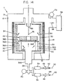
- Figure 14 presents a sectional schematic view of a furnace for a conventional CVI/CVD process.
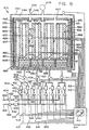
- Figure 15 presents a sectional schematic view of a furnace for simultaneously densifying a large number of porous structures by a CVI/CVD process according to an aspect of the invention.
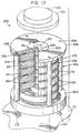
- Figure 16 presents a perspective view of a preheater according to an aspect of the invention.
- Figure 17 presents a fixture with porous structures according to an aspect of the invention.
- Figure 18 presents a fixture with porous structures according to an aspect of the invention.
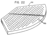
- Figure 22 presents an alternate cover plate for use with the preheater of Figure 16.
- Figure 26 presents a graph showing average deposition rate versus normalized reactant gas flow for a variety of reactor volume pressures according to an aspect of the invention.
- FIG. 1 a schematic depiction is presented of a CVI/CVD furnace 10 adapted to deposit a matrix within a porous structure 22 by a CVI/CVD process according to an aspect of the invention.
- the furnace 10 has a shell 13 with an inner surface 12 that defines a furnace volume 14, and a gas inlet 16 for introducing a gas into the furnace 10.
- a susceptor 30 is disposed around the reactor volume 35 and is induction heated by an induction coil 20 according to methods well known in the art. Other methods of heating may also be utilized such as resistance heating and microwave heating, any of which are considered to fall within the purview of the invention.
- An insulation barrier 31 is disposed between the susceptor 30 and the induction coil 20.
- the susceptor 30 has an inner surface 33 that defines a reactor volume 35 which is included within the furnace volume 14.
- the porous structure 22 is disposed within a fixture 2 in the reactor volume 35 and is predominantly heated by radiation from the susceptor 30.
- a vacuum apparatus 58 comprising a vacuum pump or steam vacuum system is in fluid communication with an exhaust 32 and evacuates the furnace volume 14 to a pressure below atmospheric pressure.
- a reactant gas is introduced into the reactor volume 35 through the gas inlet 16 that receives the reactant gas from a furnace supply line 26. The reactant gas infiltrates the porous structure 22 where it cracks and deposits a matrix within the porous structure 22.
- a single type of gas or mixtures of multiple types of gases may be supplied to the gas inlet 16.
- the reactant gas comprises a mixture of two reactant gases that are introduced through a first main gas line 42 and a second main gas line 44.
- the furnace supply line 26 is in fluid communication with the first and second main gas lines 42 and 44 and the inlet 16 thereby serving to transfer the reactant gases to the furnace 10.
- a first flow meter 46 measures the quantity of flow of a first gas (indicated by arrow 50) introduced into the furnace supply line 26 through the first main supply line 42
- a second flow meter 48 measures the quantity of flow of a second gas (indicated by arrow 52) introduced into the furnace supply line 26 through the second main gas line 44.
- the flow of gas into furnace supply line 26 is controlled by a first control valve 54 which controls the flow of the first reactant gas from the first main gas line 42, and by a second control valve 56 which controls the flow of the second reactant gas from the second main gas line 44.
- the porous structure 22 includes a porous structure aperture 23.
- a tube 60 is in fluid communication with fixture 2 and the inlet 16 thereby serving to transfer the reactant gas to the fixture 2.
- the fixture 2 comprises a pair of plates 38 and 40, and the tube 60 is sealed to the gas inlet 16 and to the plate 38.
- the porous structure 22 is sealed between the plates by ring-like spacers 62 and 64; and the plates 38 and 40 are held together by tie-rods 66.
- the porous structure 22 forms a porous wall 68 disposed between the inlet 16 and the exhaust 32.
- the various aspects of the invention may be used to deposit any type of CVI/CVD deposited matrix including, but not limited to, carbon or ceramic matrix deposited within carbon or ceramic based porous structures 22.
- the invention is particularly useful for depositing a carbon matrix within a carbon-based porous structure, and especially for making carbon/carbon composite structures such as aircraft brake disks.
- the porous structure is annular and has two opposing generally planar surfaces 78 and 80 that are bounded by an inside circumferential surface 82 and an outside circumferential surface 84.
- the tie-rods 66 may be threaded on one or both ends and include nuts 67 in threaded engagement. Washers 69 may be used to distribute the load to the plates 38 and 40.
- the first portion 86 includes one surface 78 of the two opposing surfaces 78 and 80, and the second portion 88 includes the other surface 80 of the two opposing surfaces 78 and 80.
- the first portion 86 also includes the inside circumferential surface 82, and the second portion 88 includes the outside circumferential surface 84.
- FIG. 3 an alternative fixture 4 that may be used in place of fixture 2 is depicted wherein two porous structures 22 are stacked and simultaneously densified. Two ring-like spacers 64 are utilized and tie-rods 65 are longer versions of the tie-rods 66 of Figure 2.
- the reactant gas tends to crack and preferentially deposit the matrix within the portions of the porous structure 22.
- the fixture 6 utilizes all "ID" ring-like spacers 62.
- the first portion 87 includes the inside circumferential surface 82
- the second portion 89 includes the outside circumferential surface 84 and two opposing surfaces 78 and 80.
- the reactant gas tends to quickly flow through the porous structure 22 and exit near the ring-like spacer 62.
- the fixture 8 utilizes all "OD" ring-like spacers 64.
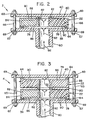
- FIG. 6 an alternative fixture 9 that may be used in place of fixture 2 for an alternative CVI/CVD process is presented.
- the process presented in Figure 6 is a "reverse flow” process wherein the reactant gas enters the porous structure 22 from the outside rather than the inside of the porous structure 22. This is accomplished by disposing the porous structure 22 between plates 38 and 41.
- Plate 41 is essentially identical to plate 40 except that plate 41 includes an aperture 43.
- a cylindrical barrier structure 350 is disposed between and sealed to plates 38 and 41.
- the barrier structure 350 encircles the porous structure 22.
- the outside diameter of surface 80 is spaced from and sealed to the plate 41 by an "OD" ring-like spacer 64.
- the outside diameter of surface 78 is spaced from and sealed by an "OD" ring-like spacer 64 to a seal plate 352, which is disposed between the porous structure 22 and plate 38.
- a plurality of spacing blocks 353 space the seal plate 352 from the plate 38 thereby forming a plurality of apertures 354.
- Reactant gas is introduced into fixture 9 the direction of arrow 92.
- the gas exhausts from fixture 9 to the reactor volume 35 through the aperture 43 as indicated by arrow 358.
- the first portion 95 includes the outside circumferential surface 84
- the second portion 97 includes the inside circumferential surface 82 and the opposing surfaces 78 and 80.
- the densified structure may be further densified by second or additional densification processes including pressure gradient CVI/CVD, conventional CVI/CVD, or resin impregnation followed by charring.
- FIG 7 presents a reverse flow process which is very similar to the Figure 6 process.
- Fixture 7 is essentially identical to fixture 9, except that fixture 7 comprises "ID" ring-like spacers 62 rather than "OD" ring like spacers 64.
- the flow of reactant gas enters the opposing surfaces 78 and 80 and the outside circumferential surface 84, and exits the inside circumferential surface 82 of porous structure 22 as indicated by arrows 101.
- the inside circumferential surface 82 is subjected to the pressure of the reactor volume 35, and the outside circumferential surface 84 and the opposing surfaces 78 and 80 are subjected to the reactant gas supply pressure.
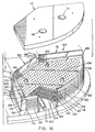
- FIG 13 presents a densified structure 341 generated by the Figure 7 process.
- the densified structure 341 comprises a zone 343 of greatest density adjacent the outside circumferential surface 84 and part of the two opposing surfaces 78 and 80.
- the density monotonically decreases from the greatest density zone 343 to a least density zone 349 with density zones 345 and 347 representing intermediate density ranges.
- the densified structure 341 has an average bulk density, and density zone 343 is typically about 120% of the average bulk density, and density zone 349 is typically about 80% of the average bulk density.
- the densified structure 341 may be further densified by second or additional densification processes including pressure gradient CVI/CVD, conventional CVI/CVD, or resin impregnation followed by charring.
- the various components of fixtures 2, 4, 6, 7, 8 and 9 are preferably formed from graphite, but any suitable high temperature resistant material may be used in the practice of the invention.
- the various joints may be sealed using compliant gaskets and/or liquid adhesives such as a graphite cement.
- the porous structures may be pressed against the ring-like spacers to form appropriate seals if the porous structures are compliant before densification.
- Suitable compliant gaskets may be formed from a flexible graphite such as EGC Thermafoil® brand flexible graphite sheet and ribbon-pack available from EGC Enterprises Incorporated, Mentor, Ohio, U.S.A. Comparable materials are available from UCAR Carbon Company Inc., Cleveland, Ohio, U.S.A.
- a conventional CVI/CVD process may be carried out using a CVI/CVD furnace 11 as depicted in Figure 14.
- Furnace 11 is very similar to Furnace 10 (see Figure 1).
- the fixture 2 is eliminated and replaced with a fixture 360.
- Fixture 360 comprises a support plate 362 disposed on a plurality of support posts 364.
- the porous structure is disposed on a plurality of spacers 368 that separate the porous structure 22 from the plate 362 permitting dispersion of the reactant gas between the plate 362 and the porous structure 22.
- the support plate 362 has a multitude of perforations (not shown) to permit dispersion of reactant gas through the plate and around the porous structure 22.
- the support posts 364, spacers 368, and perforated support plate 362 are preferably formed from graphite.
- Tube 60 of Figure 1 is replaced by a larger diameter tube 366.
- Gas enters the furnace volume and freely expands as indicated by arrows 370.
- the gas passes over the porous structure as indicated by arrows 34 and exhausts from the furnace volume 14 to the vacuum device 58 as indicated by arrows 36 and 28.
- Normally, only one temperature sensor 76 is used which generally senses the temperature of porous structure 22.
- the pressure measured by pressure sensor 70 is only slightly greater than the pressure measured by pressure sensor 72 during a conventional CVI/CVD process.
- a mixture of reactant gases may be introduced from main supply lines 42 and 44, as previously described in relation to Figure 1.
- each annular porous structure 22 has a surface area with a majority (more than 50%) of the surface area of each annular porous structure being exposed to the reactant gas as it enters or leaves the porous structure 22. As much of the porous structure surface area as possible is preferably exposed to the reactant gas. Preferably, at least 80% of the porous structure surface area is exposed.
- a CVI/CVD furnace 400 and an apparatus 402 for introducing a first reactant gas into the furnace 400 is presented.
- Furnace 400 and apparatus 402 are particularly suited for simultaneously densifying large quantities of porous articles, for example five hundred to one thousand annular preforms for manufacturing aircraft brake disks.
- a first main gas line 404 supplies the first reactant gas as indicated by arrow 406.
- a plurality of furnace supply lines 408 are in fluid communication with the first main gas line 404 and the CVI/CVD furnace 400.
- a plurality of first flow meters 410 measures a quantity of first reactant gas flow through each furnace supply line 408.
- a plurality of first control valves 412 are configured to control the quantity of flow of the first reactant gas through each furnace supply line 408.
- Apparatus 402 comprises four supply lines 408, four control valves 412, and four flow meters 410, but the invention is not limited to four of each component, since the number may be increased or decreased as required.
- the furnace 400 and reactant gas supply apparatus 402 are controlled by a controller 414.
- Each flow meter 410 may communicate the measured quantity of flow to the controller 414 via a first flow sensor line 416, and the controller 414 may control each control valve 412 via a first valve control line 418.
- the controller 414 is preferably micro-processor based and comprises a screen 415 for monitoring the various conditions and control states in the reactant gas supply apparatus 402 and the furnace 400.
- each furnace supply line 408 comprises one first flow meter 410 and one first control valve 412, as shown in Figure 15, and a first main control valve 420 disposed within the first main gas line 404.
- the first main control valve 420 preferably controls pressure in the first main gas line 404.
- a first main flow meter 422 may also be disposed within the first main gas line 404.
- a mixture of gases may be supplied to furnace 400 by providing at least a second main gas supply line 424 for supplying a second reactant gas as indicated by arrow 426.
- a plurality of second flow meters 430 are provided that measure a quantity of second reactant gas flow through each furnace supply line 408 with a plurality of second control valves 432 configured to control the quantity of flow of the second reactant gas through each furnace supply line 408.
- Each second flow meter 430 may communicate the measured quantity of flow to the controller 414 via a second flow sensor line 436, and the controller 414 may control each second control valve 432 via a second valve control line 438.
- the second main gas line 424 comprises a second main control valve 440 disposed within the second main gas line 424.
- a second main flow meter 442 may also be disposed within the second main gas line 424.
- the second main control valve 440 preferably controls pressure in the second main gas line 424.
- the furnace 400 comprises a furnace shell 444 that defines a furnace volume 446.
- a reactor volume 447 is included within the furnace volume 446.
- the furnace supply lines 408 are in fluid communication with the reactor volume 447.
- a vacuum apparatus 448 is in fluid communication with the furnace volume 446 and reactor volume 447 via exhaust stacks 450.
- the vacuum apparatus 448 reduces the pressure in furnace volume 446 to a vacuum pressure (below atmospheric) and may comprise any suitable device such as a vacuum pump or steam vacuum system with appropriate filters and scrubbers that remove undesirable by-products from the spent reactant gas.
- the reactant gas from a given furnace supply line 408 is introduced into a corresponding preheater 458.
- a first preheater 458 is disposed within the reactor volume 447 and has an inlet 460 and an outlet 461.
- the first preheater 458 is sealed such that substantially all of the reactant gas introduced into the inlet 460 from a corresponding furnace supply line 408 is heated and leaves the preheater through the corresponding outlet 461 where it infiltrates at least one porous structure disposed within the furnace.
- the term "substantially all of the gas" is intended to allow for a small amount of leakage.
- the first preheater 458 is heated to a preheater temperature greater than the reactant gas temperature from the corresponding furnace supply line 408.
- the porous structure is also heated.
- the porous structure comprises a first porous wall 452 disposed within the reactor volume 447.
- the first porous wall 452 is preferably annular and comprises a first top plate 454 that seals the upper open end of the first porous wall 452, thereby defining a first enclosed cavity 456.
- the other end of the first porous wall 452 is sealed against the first preheater 458, with the first preheater outlet 461 in fluid communication with the first enclosed cavity 456.
- a first flow of reactant gas is introduced into the first preheater 458, and then passes into the first enclosed cavity 456 at a pressure greater than the pressure within the reactor volume 447.
- one side of the first porous wall 452 is subjected to a greater reactant gas pressure than the other side of the first porous wall.
- the inner side of the porous wall 452 (the enclosed cavity 456) is subjected to a greater reactant gas pressure than the outer side of porous wall 452.
- the pressure difference forces the first flow of reactant gas to disperse through the first porous wall 452 where the heated gas cracks and deposits a binding matrix within the heated first porous wall 452.
- the remaining gas and any by-products then exit the first porous wall 452 and are exhausted from the reactor volume 447 through exhaust stacks 450 by vacuum apparatus 448.
- the reactant gas is forced to disperse through the annular porous wall by introducing the reactant gas to the CVI/CVD furnace and exhausting the reactant gas from the CVI/CVD furnace on opposite sides of the annular porous wall.
- At least one exhaust stack 450 is preferably provided between each pair of porous walls.
- each preheater 458 may supply reactant gas to more than one annular porous wall 452.
- Furnace 400 may be heated by any method known in the art for heating a CVI/CVD furnace, including resistance heating and induction heating.
- the preheater 458 and porous wall 452 are radiation heated by a susceptor 462 that encloses the first preheater 458 and porous wall 452 on all sides.
- the susceptor 462 defines the reactor volume 447 and a floor 463 upon which the first preheater 458 rests.
- the susceptor 462 preferably comprises a circumferential portion 464 and the furnace 400 comprises a first induction coil 466, a second induction coil 468, and a third induction coil 470 that encircle the circumferential portion 464.
- the susceptor 462 is inductively coupled with the induction coils 466, 468, and 470 which transfer energy to the susceptor 462, where it is transformed into heat in a manner well known in the art. Maintaining a uniform temperature from the bottom to the top of a CVI/CVD furnace during densification of a large number of porous structures (hundreds) may be difficult. The rate at which the gas cracks and deposits the binding matrix is largely determined by temperature assuming the reactant gas concentration is sufficient. Thus, variations in porous structure temperature throughout the furnace cause corresponding variations in bulk density gain which can reduce yield during a given CVI/CVD run. Incorporating multiple induction coils, as depicted in Figure 15, permits application of differing amounts of heat along the length of the furnace. A more uniform porous structure temperature profile along the length of the furnace (in direction of gas flow) may thus be obtained.
- a first gas temperature of the first flow of reactant gas is sensed proximate the first preheater outlet 461 by a first temperature sensor 490.
- Temperature sensor 490 may comprise a Type K thermocouple with appropriate protective sheathing.
- the preheater temperature may be adjusted to achieve a desired gas temperature. Measuring the preheater temperature directly is not necessary since the preheater temperature is convectively related to the gas temperature at the outlet 461.
- the preheater temperature is adjusted by increasing or decreasing the heating of the first preheater 458.
- the susceptor wall 464 is comprised of a first susceptor wall portion 467, a second susceptor wall portion 469, and a third susceptor wall portion 471.
- the first induction coil 466 is inductively coupled to the first susceptor wall portion 467 in a manner that transforms electrical energy from the first induction coil 466 to heat energy in the first susceptor wall portion 467.
- the first preheater 458 is predominantly heated by radiation heat energy from the first susceptor wall portion 467 which is adjacent the first induction coil 466. Thus, the first preheater temperature may be adjusted by adjusting electrical power to the first induction coil 466.
- the electrical power to the second induction coil 468 and 470 may be adjusted as necessary to maintain a desirable porous structure temperature profile along the length of the furnace.
- the first preheater 458 is preferably disposed proximate the first susceptor wall portion 467 which improves the transfer of heat energy by radiation.
- the temperature sensed by first temperature sensor 490 may be transmitted to the controller 414 via a first temperature sensor line 494.
- the controller may process the temperature sensor information and automatically adjust electrical power to the first induction coil 466 as necessary to achieve a desired temperature of the first gas flow as it leaves the first preheater outlet 461.
- a preheater may be disposed proximate the center of the furnace and surrounded by adjacent preheaters that are proximate the susceptor wall and block transfer of heat energy by radiation to the center preheater.
- the center preheater is heated predominantly by conduction from the adjacent preheaters that are heated by radiation.
- the center preheater is indirectly heated by radiation from the susceptor wall and the center preheater temperature may be controlled by varying power to the first induction coil 466.
- the preheaters could be resistance heated which would permit direct control of the heat energy supplied to each preheater. Any such variations are considered to be within the purview of the invention.
- a second porous wall 472 may be sealed to a second preheater 478 with the second porous wall having a second top plate 474.
- the second preheater 478 has a second preheater inlet 480 and a second preheater outlet 481.
- a second temperature sensor 492 may be provided for sensing the temperature of the second flow of reactant gas as it exits the second preheater out/let 481.
- the second porous wall 472 defines a second enclosed cavity 476 that is in fluid communication with the second preheater outlet 481.
- a second flow of gas is introduced to the second preheater through a corresponding furnace supply line 408 and is forced to disperse through the second porous wall 472 and exit the furnace volume 446 in the same manner as described in relation to the first porous wall 452.
- one side of the second porous wall 472 is subjected to a greater pressure than the other side of the second porous wall.
- the second preheater 478 and second porous wall 472 are heated predominantly by radiation from the susceptor wall 464.
- the second preheater 478 is heated to a preheater temperature greater than the reactant gas temperature from the corresponding furnace supply line 408.
- the heated gas infiltrates the second porous wall 472 where it cracks and deposits a binding matrix.
- a second temperature sensor 492 may be provided proximate the second preheater outlet 481.
- the temperature sensed by second temperature sensor 492 may be transmitted to the controller 414 via a second temperature sensor line 496.
- the controller 414 may process the temperature sensor information and automatically adjust electrical power to the first induction coil 466 as necessary to achieve a desired temperature of the second gas flow as it leaves the second preheater outlet 481. Electrical power to the first induction coil 466 may also be manually adjusted as necessary in order to achieve the desired gas flow temperature.
- At least a third porous wall may be densified by a similar pressure gradient CVI/CVD process wherein at least a third flow of reactant gas is forced to disperse through at least the third porous wall by subjecting one side of at least the third porous wall to a greater pressure than the other side of at least the third porous wall, and the third flow of gas may be independently controlled.
- Additional porous walls may be added and densified in an identical manner using additional furnace supply lines 408 and additional preheaters. Additional preheaters and temperature sensors for sensing temperature of the gas flow proximate the outlet of each additional preheater may be provided as required.
- the invention permits simultaneous densification of large numbers of porous walls.
- a porous wall temperature sensor 498 may be provided in close proximity to the first porous wall 452 for sensing a first porous wall temperature.
- the first porous wall temperature may be increased or decreased by increasing or decreasing the first flow of reactant gas that passes through the first porous wall 452.
- the first flow of reactant gas may be at a lesser temperature than the porous structure as it exits the first preheater outlet 461. Increasing the first flow of reactant gas at this lesser temperature tends to decrease the porous wall temperature and decreasing the flow tends to increase the porous wall temperature. The reverse would apply if the first flow of reactant gas was at a greater temperature than the first porous wall 452.
- the first porous wall temperature sensor 498 may communicate with the controller 414 via a first porous wall temperature sensor line 502 which permits automatic or manual control of the first gas flow as necessary to achieve a desired first porous wall temperature.
- a second porous wall temperature may be similarly sensed by a second porous wall temperature sensor 500.
- the second porous wall temperature sensor 500 may communicate with the controller 414 via a second porous wall temperature sensor line 504 which permits automatic or manual control of the second gas flow as necessary to achieve a desired second porous wall temperature by increasing or decreasing the second gas flow.
- Temperature of third and additional porous walls may be sensed and controlled in similar manner.
- Each individual flow of gas from the furnace supply lines 408 may be independently controlled in order to influence the CVI/CVD deposition process by virtue of the reactant gas supply apparatus 402.
- porous wall temperature sensors may also be inserted directly in to the porous walls as indicated by temperature sensor 506.
- a thermocouple may be placed between an adjacent pair of annular porous structures if the porous wall is formed from a stack of porous structures.
- Porous wall temperature may also be sensed by an optical pyrometer 548 focused through a window 546 on an optical target 544 disposed between an adjacent pair of porous walls 452 and 472.
- a preheater 100 is presented which is a preferred embodiment for the preheaters 458 and 478 of Figure 15.
- the preheater 100 is described in more detail in a copending United States patent application entitled APPARATUS FOR USE WITH CVI/CVD PROCESSES, filed the same day as the present application naming James W. Rudolph, Mark J. Purdy, and Lowell D. Bok as inventors, and which is fully incorporated herein by reference.
- the preheater 100 comprises a sealed duct structure 102 disposed within the furnace 10 and resting on the susceptor floor 463.
- the preheater 100 receives gas from the gas inlet 460 ( Figure 15).
- the gas inlet 460 may be connected to one or more perforated tubes 19 which promote dispersion of the gas throughout the sealed duct structure 102.
- Preheater 100 comprises a sealed baffle structure 108 that rests upon a sealed duct structure 102.
- the sealed baffle structure 108 comprises an array of spaced perforated plates 128 and 129 with a bottom perforated plate comprising a baffle structure inlet 104 and a top perforated plate comprising a baffle structure outlet 106.
- the sealed duct structure 102 and sealed baffle structure 108 are sealed to each other, and the sealed duct structure 102 is sealed to the susceptor floor 463 at joint 118 so that gas cannot avoid flowing through the sealed baffle structure 108.
- the sealed duct structure 102 comprises at least two pieces 119, 120, and 121, upper ring 122 and lower ring 123 which together form several sealed joints 124, 125, 166, 168, 170, 172, and 174.
- the support bars 119, 120, and 121, and lower ring 123 support the weight of the sealed baffle structure 108.
- a cover plate 110 preferably adjoins the sealed duct structure 102 disposed over the baffle structure outlet 106.
- the cover plate 110 serves to support the porous structure fixtures.
- Cover plate 110 is adapted for use with a pressure gradient CVI/CVD process and comprises a plurality of apertures 114 and 116 with each aperture providing reactant gas to an annular porous wall.
- the cover plate 110 is sealed to the sealed duct structure 102 by a compliant gasket placed in the joint between the sealed duct structure 102 and the cover plate 110.
- the perforated plates 128 and 129 are coterminous and arranged in a stack that defines a baffle structure perimeter 132.
- Each sealed baffle structure plate 128 comprises an array of perforations 130, with the array of perforations 130 of one susceptor plate 128 being misaligned with the array of perforations 131 of an adjacent susceptor plate 129.
- This arrangement greatly facilitates transfer of heat by radiation from the susceptor wall 464 directly to the perforated plates 128 and 129. The heat is transferred by conduction along plates 128 and 129 and to the gas by forced convection.
- the baffle structure perimeter 132 is sealed by compliant gaskets 134 and comprises the outer plane-wise limit of each susceptor plate 128 and 129 and is disposed in close proximity to the susceptor wall 464.
- the compliant gaskets 134 also serve to space the perforated plates 128 and 129 from each other.
- the sealed duct structure 102 preferably defines a ledge 136 upon which said sealed baffle structure 108 rests.
- the support bars 119, 120, and 121 define the ledge in combination with lower ring 123.
- a plurality of posts 140 may be provided that facilitate loading the baffle structure 108 into the furnace and also further support the sealed baffle structure 108 and cover plate 110.
- Each post 140 comprises an enlarged portion that defines a seat (not shown) which rests on the susceptor floor 463.
- the sealed baffle structure 108 rests upon the seat.
- the various components of preheater 100 are preferably formed from monolithic graphite.
- the various sealed joints are preferably formed using compliant gaskets and/or graphite cement. Suitable compliant gaskets may be formed from a flexible graphite such as EGC Thermafoil® and Thermabraid® brand flexible graphite sheet and ribbon-pack available from EGC Enterprises Incorporated, Mentor, Ohio, U.S.A. Comparable materials are available from UCAR Carbon Company Inc., Cleveland, Ohio, U.S.A.
- the porous walls 452 and 472 of Figure 15 may be formed from stacks of annular porous structures, which is particularly preferred for manufacturing aircraft brake disks.
- a preferred fixture 200 is presented for densifying a stack of annular porous structures 22 by a CVI/CVD process.
- the fixture 200 is described in more detail in a copending United States patent application entitled APPARATUS FOR USE WITH CVI/CVD PROCESSES, filed the same day as the present application naming James W. Rudolph, Mark J. Purdy, and Lowell D. Bok as inventors.
- Fixture 200 is preferably used with the preheater 100 of Figure 16.
- the porous structures 22 are arranged in a stack 202.
- the fixture comprises a base plate 204, a spacing structure 206, and a top plate 208.
- the top plate 208 optionally has an aperture 210 which is sealed by a cover plate 212, compliant gasket 213, and weight 214.
- the base plate 204 is adapted to engage the cover plate 110 and has a base plate aperture (item 216 in Figure 18) that aligns with one of the cover plate apertures 114 or 116.
- the base plate 204 is preferably located by a plurality of conical pins 226.
- the base plate 204 has mating conical base plate holes that are aligned with and receive the conical pins 226. This arrangement facilitates aligning the base plate aperture with a corresponding cover plate aperture.
- the base plate 204 is preferably sealed to the cover plate 110 by use of a compliant gasket.
- the top plate 208 is spaced from and faces the base plate 204.
- the spacing structure 206 is disposed between and engages the base plate 204 and the top plate 208.
- the spacing structure comprises a plurality of spacing posts 218 disposed about the stack of porous structures and extending between the base plate 204 and the top plate 208.
- Each post 218 has pins 220 at either end that are received in mating holes 224 in base plate 204 and top plate 208.
- the spacing structure 206 preferably comprises at least three posts 218.
- the spacing structure 206 could also be formed as a single piece, and other arrangements for engaging the base plate 204 and top plate 208 are possible, any of which are considered to be within the purview of the invention.
- At least one ring-like spacer 234 is disposed within the stack 202 of porous structures 22 between each pair of neighboring porous structures 22.
- the ring-like spacer 234 encircles the neighboring porous structure apertures 23.
- At least one of the ring-like spacers 234 is preferably disposed between the base plate 204 and porous structure 22 adjacent the base plate 204, and between the top plate 208 and porous structure 22 adjacent the top plate 208.
- the base plate 204, the stack of porous structures 202, and the at least one ring-like spacer 234 define an enclosed cavity 236 extending from the base plate aperture (item 216 in Figure 18), including each porous structure aperture 23, and terminating proximate the top plate 208.
- the outside diameter of ring-like spacer 234 is 55.6 cm (21.9 inches) and the spacer inside diameter is 50.55 cm (19.9 inches) for processing annular porous structures 22 having an outside diameter of 53.34 cm (21 inches).
- the ring-like spacers are preferably at least 0.635 cm (0.25 inch) thick.
- the spacing structure 207 comprises at least one intermediate plate 272 disposed between the base plate 204 and the top plate 208 that divides the stack of porous structures 203.
- the posts 218 extend between the top plate 208 and one of the intermediate plates 272, between the base plate 204 and another of the intermediate plates 272, and between adjacent pairs of intermediate plates 272.
- fixture 201 is essentially identical to fixture 200.
- Each intermediate plate 272 has an intermediate plate aperture 274 therethrough is sandwiched between a pair of the porous structures 22.
- the enclosed cavity 236 further includes each intermediate plate aperture 274.
- At least one of the ring-like spacers 234 is disposed on either side of and sealed to the intermediate plate 272 between the intermediate plate 272 and the porous structures 22.
- Multiple fixtures 201 may be stacked.
- the base plate 204 from one fixture 201 engages the top plate 208 of a lower fixture 201 with the upper fixture base plate aperture 216 in fluid communication with the lower fixture top plate aperture 210.
- the enclosed cavity extends from one fixture 201 to the next until being terminated by the cover plate 212 disposed over the uppermost top plate aperture 210.
- the base plate 204 is provided with conical holes 230 that receive a conical portion of the conical pins 226, and the cover plate 110 is provided with holes 228 that receive a cylindrical portion of the conical pins 226.
- Fixture 299 is essentially identical to fixture 200, except stack 302 comprises "OD" (outside diameter) ring-like spacers 234 disposed around the outside diameter of each porous structure 22 alternated with "ID" (inside diameter) ring-like spacers 284 disposed around the inside diameter of each porous structure.
- the OD ring-like spacers 234 preferably have an inside diameter 233 slightly less than the porous structure outside diameter 608, and an outside diameter 235 that is generally coterminous with the porous structure outside diameter 608.
- the ID ring-like spacers 284 preferably have an outside diameter 286 slightly greater than the porous structure inside diameter 610, and an inside diameter 288 that is generally coterminous with the porous structure inside diameter 610. With ID ring-like spacers 284, the porous structure outside diameter 608 is greater than the outside diameter 286 of the ring like spacer 284.
- the wall thickness of each ring-like spacer 234 and 284 is preferably minimized in order to maximize exposure of the porous structure surface area to the reactant gas as it enters or leaves each porous structure 22.
- Fixture 301 is essentially identical to fixture 200, except stack 303 comprises all "ID" ring-like spacers 284 disposed around the inside diameter of each porous structure.
- the various components of fixtures 200, 201, 299 and 301 are preferably formed from graphite.
- the various joints comprised within the fixtures are preferably sealed using compressible ring-like gaskets from a flexible graphite material, as previously disclosed. If the porous structures 22 are compressible, they may be compressed directly against the ring-like spacers 234 to provide a sufficient seal and eliminate the need for compressible gaskets between the porous structures 22 and ring-like spacers 234.
- the ring-like spacers prior to use are preferably seal-coated with a surface deposition of pyrolytic carbon which facilitates removal of the ring-like spacer from a densified porous structure following deposition of the matrix.
- Fixtures similar to fixtures 200 and 201 may be used in a conventional CVI/CVD process in which the ring-like spacers 234 are replaced by spacer blocks that separate the porous structures and permit the reactant gas to freely pass through, over, and around the porous structures 22.
- cover plate 110 may be replaced by cover plate 152 of Figure 22 in order to promote dispersion of the reactant gas throughout the furnace volume.
- Cover plate 152 comprises an array of perforations 153. Sealing the various joints comprised within a fixture adapted for a conventional CVI/CVD process is not necessary or desirable.
- the first carbon matrix and second carbon matrix preferably comprise a substantially rough laminar microstructure.
- a rough laminar microstructure has a greater density (about 2.1 g/cm 3 ), greater thermal conductivity, and lesser hardness than smooth laminar microstructure (1.9-2.0 g/cm 3 or less).
- Rough laminar microstructure is particularly preferred in certain carbon/carbon aircraft brake disks.
- Microstructure may be optically characterized as described by M.L. Lieberman and H.O. Pierson, Effect of Gas Phase Conditions on Resultant Matrix Pyrocarbons in Carbon/Carbon Composites , 12 Carbon 233-41 (1974).
- crushed apparent density is measured by cutting a specimen from a densified porous structure and fracturing the specimen between parallel steel platens of a load testing machine.
- the specimen is preferably fractured in a manner that maintains the specimen in one piece. This may be accomplished by compressing the sample past the yield point without fragmentation.
- Apparent density is then measured according to the Archimedes technique using mineral spirits such as Isopar M (synthetic isoparaffinic hydrocarbon) available from Exxon Chemical Americas, Houston, Texas, U.S.A. Vacuum is used to force the mineral spirits into the structure.
- Apparent density is a measurement of the density of the material that is impervious to penetration by the mineral spirits.
- crushed apparent density of a pulverized sample may be measured using a helium pyconometer. Measurements of densified porous structures processed similar to densified porous structure 600 demonstrated that the crushed impervious density adjacent the inside circumferential surface 82 was consistently at least 0.2% greater, and may be as much as 0.4% and 0.5% greater, than adjacent the outside circumferential surface 84. Thus, crushed apparent density tends to generally decrease from the inside surface 82 to the outside surface 84.
- Thermal conductivity of densified porous structures similar to densified porous structure 600 was measured in two directions: normal to the opposing surfaces 78 and 80 which will be referred to as “thermal flat conductivity”, and normal to the circumferential surfaces 82 and 84 (in the radial direction) which will be referred to as “thermal edge conductivity.”
- Thermal flat conductivity of circumferential portion 514 was at least 5% less than circumferential portion 512 when measured at the opposing surfaces 78 and 80.
- Thermal flat conductivity of circumferential portion 514 was at least 12% less than circumferential portion 512 at one-half of the distance between opposing surfaces 78 and 80.
- Thermal edge conductivity of circumferential portion 514 was at least 5% less than circumferential portion 512 when measured at the opposing surfaces 78 and 80. Thermal edge conductivity of circumferential portion 514 was at least 4% less than circumferential portion 512 when measured at one-half of the distance between opposing surfaces 78 and 80. Thus, thermal conductivity tends to generally decrease from the inside circumferential portion 512 to the outside circumferential portion 514. This trend is induced by the first matrix being more graphitized than the second matrix.
- a base-line was established for a conventional CVI/CVD process as follows.
- a fibrous textile structure about 1.5 inch thick was manufactured according to Figures 1 through 4 of United States Patent 4,790,052 starting with a 320K tow of unidirectional polyacrylonitrile fiber.
- An annular porous structure was then cut from the textile structure having an outside diameter of about 19.05 cm (7.5 inch), an inside diameter of about 6.35 cm (2.5 inch).
- the annular porous structure was then pyrolyzed to transform the fibers to carbon.
- the pyrolyzed porous structure, having a bulk density of 0.49 g/cm 3 was then placed in a furnace similar to furnace 11 of Figure 14.
- Pressure was reduced to 1.33 kPa (10 torr) inside the furnace volume and the furnace was heated and stabilized at a temperature of about 1015.5 °C (1860 °F) when measured by a temperature sensor positioned as temperature sensor 76 of Figure 14.
- a reactant gas mixture was introduced as described in relation to Figure 14 and allowed to freely disperse over and around the porous structure in a manner typical of a conventional CVI/CVD process.
- the reactant gas mixture was comprised of 87% (volume percent) natural gas and 13% propane at a flow rate of 4000 sccm (standard cubic centimeters per minute) and a residence time of about 1 second in the reactor volume.
- the natural gas had a composition of 96.4% methane (volume percent), 1.80% ethane, 0.50% propane, 0.15% butane, 0.05% pentane, 0.70% carbon dioxide, and 0.40% nitrogen.
- the process was stopped three times to measure bulk density gain of the porous structure. Total deposition process time was 306 hours. An average rate of deposition was calculated for each of the three densification runs.
- the test conditions and data from this example are presented in Table 1, including cumulative deposition time (Cum. Time) and total density gain (Density Gain) at each cumulative time noted.
- the carbon matrix deposited within the densified porous structure at the end of the process comprised nearly all rough laminar microstructure with minimal deposits of smooth laminar microstructure at the surface of the porous structure.
- curves representing densification rate versus normalized flow are presented. Additional tests were run according to Example 6 (pressure gradient with all "OD" spacers) above except the furnace volume pressure and flow rates of reactant gas were varied from one test to the next. The data from these tests is presented in Table 10. Data from Table 10 is presented as three curves 532, 534, and 536. Curve 532 represents data at a furnace volume pressure of 1.33 kPa (10 torr) when measured by a pressure sensor such as sensor 72 of Figure 1. Curve 534 represents data at a furnace volume pressure of 3.33 kPa (25 torr) when measured by a pressure sensor such as sensor 72 of Figure 1.
- Curve 532 represents data at a furnace volume pressure of 6.66 kPa (50 torr) when measured by a pressure sensor such as sensor 72 of Figure 1.
- the matrix deposited in all of these tests comprised all rough laminar microstructure.
- additional gains in densification rate may be realized by increasing the furnace volume pressure (Reactor Pressure) while maintaining a desired rough laminar microstructure. This was a surprising discovery. Cum. Time (hour) Reactor Pressure kPa (torr) Gas Rate (sccm) Flow Part Temp.
Landscapes
- Chemical & Material Sciences (AREA)
- Engineering & Computer Science (AREA)
- Materials Engineering (AREA)
- Mechanical Engineering (AREA)
- Chemical Kinetics & Catalysis (AREA)
- Organic Chemistry (AREA)
- General Chemical & Material Sciences (AREA)
- Metallurgy (AREA)
- General Engineering & Computer Science (AREA)
- Ceramic Engineering (AREA)
- Composite Materials (AREA)
- Manufacturing & Machinery (AREA)
- Structural Engineering (AREA)
- Chemical Vapour Deposition (AREA)
- Superconductors And Manufacturing Methods Therefor (AREA)
- Crystals, And After-Treatments Of Crystals (AREA)
- Braking Arrangements (AREA)
- Secondary Cells (AREA)
- Supplying Of Containers To The Packaging Station (AREA)
- Preparing Plates And Mask In Photomechanical Process (AREA)
Abstract
Description
- The invention relates to the field of high temperature composites made by the chemical vapor infiltration (CVI) and deposition (CVD) of a binding matrix within a porous structure. More particularly, the invention relates to CVI/CVD processes for forcing infiltration of a reactant gas into a porous structure, apparatus for carrying out those processes, and the resulting products.
- Chemical vapor infiltration and deposition (CVI/CVD) is a well known process for depositing a binding matrix within a porous structure. The term "chemical vapor deposition" (CVD) generally implies deposition of a surface coating, but the term is also used to refer to infiltration and deposition of a matrix within a porous structure. As used herein, the term CVI/CVD is intended to refer to infiltration and deposition of a matrix within a porous structure. The technique is particularly suitable for fabricating high temperature structural composites by depositing a carbonaceous or ceramic matrix within a carbonaceous or ceramic porous structure resulting in very useful structures such as carbon/carbon aircraft brake disks, and ceramic combustor or turbine components. The generally known CVI/CVD processes may be classified into four general categories: isothermal, thermal gradient, pressure gradient, and pulsed flow. See W.V. Kotlensky, Deposition of Pyrolytic Carbon in Porous Solids; 8 Chemistry and Physics of Carbon, 173, 190-203 (1973); W.J. Lackey, Review, Status, and Future of the Chemical Vapor Infiltration Process for Fabrication of Fiber-Reinforced Ceramic Composites, Ceram. Eng. Sci. Proc. 10[7-8] 577, 577-81 (1989) (W.J. Lackey refers to the pressure gradient process as "isothermal forced flow"). In an isothermal CVI/CVD process, a reactant gas passes around a heated porous structure at absolute pressures as low as a few millitorr. The gas diffuses into the porous structure driven by concentration gradients and cracks to deposit a binding matrix. This process is also known as "conventional" CVI/CVD. The porous structure is heated to a more or less uniform temperature, hence the term "isothermal," but this is actually a misnomer. Some variations in temperature within the porous structure are inevitable due to uneven heating (essentially unavoidable in most furnaces), cooling of some portions due to reactant gas flow, and heating or cooling of other portions due to heat of reaction effects. In essence, "isothermal" means that there is no attempt to induce a thermal gradient that preferentially affects deposition of a binding matrix. This process is well suited for simultaneously densifying large quantities of porous articles and is particularly suited for making carbon/carbon brake disks. With appropriate processing conditions, a matrix with desirable physical properties can be deposited. However, conventional CVI/CVD may require weeks of continual processing in order to achieve a useful density, and the surface tends to densify first resulting in "seal-coating" that prevents further infiltration of reactant gas into inner regions of the porous structure. Thus, this technique generally requires several surface machining operations that interrupt the densification process.
- In a thermal gradient CVI/CVD process, a porous structure is heated in a manner that generates steep thermal gradients that induce deposition in a desired portion of the porous structure. The thermal gradients may be induced by heating only one surface of a porous structure, for example by placing a porous structure surface against a susceptor wall, and may be enhanced by cooling an opposing surface, for example by placing the opposing surface of the porous structure against a liquid cooled wall. Deposition of the binding matrix progresses from the hot surface to the cold surface. The fixturing for a thermal gradient process tends to be complex, expensive, and difficult to implement for densifying relatively large quantities of porous structures.
- In a pressure gradient CVI/CVD process, the reactant gas is forced to flow through the porous structure by inducing a pressure gradient from one surface of the porous structure to an opposing surface of the porous structure. Flow rate of the reactant gas is greatly increased relative to the isothermal and thermal gradient processes which results in increased deposition rate of the binding matrix. This process is also known as "forced-flow" CVI/CVD. Prior fixturing for pressure gradient CVI/CVD tends to be complex, expensive, and difficult to implement for densifying large quantities of porous structures. An example of a process that generates a longitudinal pressure gradient along the lengths of a bundle of unidirectional fibers is provided in S. Kamura, N. Takase, S. Kasuya, and E. Yasuda, Fracture Behaviour of C Fiber/ CVD C Composite, Carbon '80 (German Ceramic Society) (1980). An example of a process that develops a pure radial pressure gradient for densifying an annular porous wall is provided in United States Patents 4,212,906 and 4,134,360. The annular porous wall disclosed by these patents may be formed from a multitude of stacked annular disks (for making brake disks) or as a unitary tubular structure. For thick-walled structural composites, a pure radial pressure gradient process generates a very large, undesirable density gradient from the inside cylindrical surface to the outside cylindrical surface of the annular porous wall. Also, the surface subjected to the high pressure tends to densify very rapidly causing that surface to seal and prevent infiltration of the reactant gas to low density regions. This behavior seriously limits the utility of the pure radial pressure gradient process.
- Finally, pulsed flow involves rapidly and cyclically filling and evacuating a chamber containing the heated porous structure with the reactant gas. The cyclical action forces the reactant gas to infiltrate. the porous structure and also forces removal of the cracked reactant gas by-products from the porous structure. The equipment to implement such a process is complex, expensive, and difficult to maintain. This process is very difficult to implement for densifying large numbers of porous structures.
- Many workers in the art have combined the thermal gradient and pressure gradient processes resulting in a "thermal gradient-forced flow" process. Combining the processes appears to overcome the shortcomings of each of the individual processes and results in very rapid densification of porous structures. However, combining the processes also results in twice the complexity since fixturing and equipment must be provided to induce both thermal and pressure gradients with some degree of control. A process for densifying small disks and tubes according to a thermal gradient-forced flow process is disclosed by United States Patent 4,580,524; and by A.J. Caputo and W.J. Lackey, Fabrication of Fiber-Reinforced Ceramic Composites by Chemical Vapor Infiltration, Prepared by the OAK RIDGE NATIONAL LABORATORY for the U.S. DEPARTMENT OF ENERGY under Contract No. DE-AD05-840R21400 (1984). According to this process, a fibrous preform is disposed within a water cooled jacket. The top of the preform is heated and a gas is forced to flow through the preform to the heated portion where it cracks and deposits a matrix. A process for depositing a matrix within a tubular porous structure is disclosed by United States Patent 4.895.108. According to this process, the outer cylindrical surface of the tubular porous structure is heated and the inner cylindrical surface is cooled by a water jacket. The reactant gas is introduced to the inner cylindrical surface. Similar forced flow-thermal gradient processes for forming various articles are disclosed by T. Hunh, C.V. Burkland, and B. Bustamante, Densification of a Thick Disk Preform with Silicon Carbide Matrix by a CVI Process, Ceram. Eng. Sci. Proc 12[9-10] pp. 2005-2014 (1991); T.M. Besmann, R.A. Lowden, D.P. Stinton, and T.L. Starr, A Method for Rapid Chemical Vapor Infiltration of Ceramic Composites, Journal De Physique, Colloque C5, supplement au n°5, Tome 50 (1989); T.D. Gulden, J.L. Kaae, and K.P. Norton, Forced-Flow Thermal-Gradient Chemical Vapor Infiltration (CVI) of Ceramic Matrix Composites, Proc.-Electrochemical Society (1990), 90-12 (Proc. Int. Conf. Chem. Vap. Deposition, 11th, 1990) 546-52. Each of these disclosures describes processes for densifying only one porous article at a time, which is impractical for simultaneously processing large numbers of composite articles such as carbon/carbon brake disks.
- In spite of these advances, a CVI/CVD process and an apparatus for implementing that process are desired that rapidly and uniformly densifies porous structures while minimizing cost and complexity. Such a process would preferably be capable of simultaneously densifying large numbers (as many as hundreds) of individual porous structures. In particular, a process is desired for rapidly and economically densifying large numbers of annular fibrous preform structures for aircraft brake disks having desirable physical properties.
- According to the present invention, a CVI/CVD process in a CVI/CVD furnace is provided, comprising the steps of:
- introducing a reactant gas into a sealed preheater disposed within the CVI/CVD furnace, the sealed preheater having a preheater inlet and a preheater outlet, the reactant gas being introduced into the preheater inlet and exiting the sealed preheater through the preheater outlet and infiltrating at least one porous structure disposed within the CVI/CVD furnace;
- heating the at least one porous structure;
- heating the sealed preheater to a preheater temperature greater than the reactant gas temperature;
- sensing a gas temperature of the reactant gas proximate the outlet;
- adjusting the preheater temperature to achieve a desired gas temperature; and,
- exhausting the reactant gas from the CVI/CVD furnace.
-
- Preferred embodiments of the process of the present invention become evident from the dependent claims.
- Figure 1 presents a schematic sectional view of a CVI/CVD furnace according to an aspect of the invention.
- Figure 2 presents a sectional view of a fixture for the CVI/CVD process according to an aspect of the invention.
- Figure 3 presents a sectional view of a fixture according to an aspect of the invention.
- Figure 4 presents a sectional view of a fixture according to an aspect of the invention.
- Figure 5 presents a sectional view of a fixture according to an aspect of the invention.
- Figure 6 presents a sectional view of a fixture according to an aspect of the invention.
- Figure 7 presents a sectional view of a fixture according to an aspect of the invention.
- Figure 14 presents a sectional schematic view of a furnace for a conventional CVI/CVD process.
- Figure 15 presents a sectional schematic view of a furnace for simultaneously densifying a large number of porous structures by a CVI/CVD process according to an aspect of the invention.
- Figure 16 presents a perspective view of a preheater according to an aspect of the invention.
- Figure 17 presents a fixture with porous structures according to an aspect of the invention.
- Figure 18 presents a fixture with porous structures according to an aspect of the invention.
- Figure 22 presents an alternate cover plate for use with the preheater of Figure 16.
- Figure 26 presents a graph showing average deposition rate versus normalized reactant gas flow for a variety of reactor volume pressures according to an aspect of the invention.
- The invention and various embodiments thereof are presented in Figures 1 through 29 and the accompanying descriptions wherein like numbered items are identical. As used herein, the term "conventional CVI/CVD" is intended to refer to the previously described isothermal CVI/CVD process.
- Referring now to Figure 1, a schematic depiction is presented of a CVI/
CVD furnace 10 adapted to deposit a matrix within aporous structure 22 by a CVI/CVD process according to an aspect of the invention. Thefurnace 10 has ashell 13 with aninner surface 12 that defines afurnace volume 14, and agas inlet 16 for introducing a gas into thefurnace 10. Asusceptor 30 is disposed around thereactor volume 35 and is induction heated by aninduction coil 20 according to methods well known in the art. Other methods of heating may also be utilized such as resistance heating and microwave heating, any of which are considered to fall within the purview of the invention. Aninsulation barrier 31 is disposed between the susceptor 30 and theinduction coil 20. Thesusceptor 30 has aninner surface 33 that defines areactor volume 35 which is included within thefurnace volume 14. Theporous structure 22 is disposed within afixture 2 in thereactor volume 35 and is predominantly heated by radiation from thesusceptor 30. Avacuum apparatus 58 comprising a vacuum pump or steam vacuum system is in fluid communication with anexhaust 32 and evacuates thefurnace volume 14 to a pressure below atmospheric pressure. A reactant gas is introduced into thereactor volume 35 through thegas inlet 16 that receives the reactant gas from afurnace supply line 26. The reactant gas infiltrates theporous structure 22 where it cracks and deposits a matrix within theporous structure 22. A single type of gas or mixtures of multiple types of gases may be supplied to thegas inlet 16. - According to a preferred embodiment, the reactant gas comprises a mixture of two reactant gases that are introduced through a first
main gas line 42 and a secondmain gas line 44. Thefurnace supply line 26 is in fluid communication with the first and secondmain gas lines inlet 16 thereby serving to transfer the reactant gases to thefurnace 10. Afirst flow meter 46 measures the quantity of flow of a first gas (indicated by arrow 50) introduced into thefurnace supply line 26 through the firstmain supply line 42, and asecond flow meter 48 measures the quantity of flow of a second gas (indicated by arrow 52) introduced into thefurnace supply line 26 through the secondmain gas line 44. The flow of gas intofurnace supply line 26 is controlled by afirst control valve 54 which controls the flow of the first reactant gas from the firstmain gas line 42, and by asecond control valve 56 which controls the flow of the second reactant gas from the secondmain gas line 44. - The
porous structure 22 includes aporous structure aperture 23. Atube 60 is in fluid communication withfixture 2 and theinlet 16 thereby serving to transfer the reactant gas to thefixture 2. Thefixture 2 comprises a pair ofplates tube 60 is sealed to thegas inlet 16 and to theplate 38. Theporous structure 22 is sealed between the plates by ring-like spacers plates rods 66. Theporous structure 22 forms aporous wall 68 disposed between theinlet 16 and theexhaust 32. - Pressure inside the furnace volume is measured by an
exhaust pressure sensor 72, and pressure inside theporous structure aperture 23 is measured by aninlet pressure sensor 70. An approximate reactant gas temperature inside theporous structure aperture 23 is measured by aflow temperature sensor 74, and porous structure temperature is approximated by astructure temperature sensor 76 which is placed in close proximity to theplate 40. As will be discussed in more detail, the temperature and pressure conditions are chosen to cause the gas to crack and deposit a matrix having certain desired properties within theporous structure 22. The various aspects of the invention may be used to deposit any type of CVI/CVD deposited matrix including, but not limited to, carbon or ceramic matrix deposited within carbon or ceramic basedporous structures 22. The invention is particularly useful for depositing a carbon matrix within a carbon-based porous structure, and especially for making carbon/carbon composite structures such as aircraft brake disks. - Referring now to Figure 2, a detailed view of the
fixture 2 for holdingporous structure 22 is presented. According to a preferred embodiment, the porous structure is annular and has two opposing generallyplanar surfaces circumferential surface 82 and anoutside circumferential surface 84. The tie-rods 66 may be threaded on one or both ends and include nuts 67 in threaded engagement.Washers 69 may be used to distribute the load to theplates - As gas disperses through the porous structure, additional gas flows through the
tube 60 and toward theporous structure 22 as indicated byarrows 92. Thus, reactant gas is continuously supplied and forced to disperse through theporous structure 22. In this example, thefirst portion 86 includes onesurface 78 of the two opposingsurfaces second portion 88 includes theother surface 80 of the two opposingsurfaces first portion 86 also includes the insidecircumferential surface 82, and thesecond portion 88 includes theoutside circumferential surface 84. - Referring now to Figure 3, an
alternative fixture 4 that may be used in place offixture 2 is depicted wherein twoporous structures 22 are stacked and simultaneously densified. Two ring-like spacers 64 are utilized and tie-rods 65 are longer versions of the tie-rods 66 of Figure 2. - The reactant gas tends to crack and preferentially deposit the matrix within the portions of the
porous structure 22. - Referring now to Figure 4, another
alternative fixture 6 that may be used in place offixture 2 for CVI/CVD process is presented. Thefixture 6 utilizes all "ID" ring-like spacers 62. In this example, thefirst portion 87 includes the insidecircumferential surface 82, and thesecond portion 89 includes theoutside circumferential surface 84 and two opposingsurfaces porous structure 22 and exit near the ring-like spacer 62. - Referring now to Figure 5, an
alternative fixture 8 that may be used in place offixture 2 for-an alternative CVI/CVD process is presented. Thefixture 8 utilizes all "OD" ring-like spacers 64. - Referring now to Figure 6, an alternative fixture 9 that may be used in place of
fixture 2 for an alternative CVI/CVD process is presented. The process presented in Figure 6 is a "reverse flow" process wherein the reactant gas enters theporous structure 22 from the outside rather than the inside of theporous structure 22. This is accomplished by disposing theporous structure 22 betweenplates Plate 41 is essentially identical to plate 40 except thatplate 41 includes anaperture 43. Acylindrical barrier structure 350 is disposed between and sealed toplates barrier structure 350 encircles theporous structure 22. The outside diameter ofsurface 80 is spaced from and sealed to theplate 41 by an "OD" ring-like spacer 64. The outside diameter ofsurface 78 is spaced from and sealed by an "OD" ring-like spacer 64 to aseal plate 352, which is disposed between theporous structure 22 andplate 38. A plurality of spacing blocks 353 space theseal plate 352 from theplate 38 thereby forming a plurality ofapertures 354. Reactant gas is introduced into fixture 9 the direction ofarrow 92. - The gas exhausts from fixture 9 to the
reactor volume 35 through theaperture 43 as indicated byarrow 358. In this example, thefirst portion 95 includes theoutside circumferential surface 84, and thesecond portion 97 includes the insidecircumferential surface 82 and the opposingsurfaces - Referring now to Figure 7, an alternative fixture 7 that may be used in place of
fixture 2 for an alternative CVI/CVD process is presented. Figure 7 presents a reverse flow process which is very similar to the Figure 6 process. Fixture 7 is essentially identical to fixture 9, except that fixture 7 comprises "ID" ring-like spacers 62 rather than "OD" ring likespacers 64. The flow of reactant gas enters the opposingsurfaces outside circumferential surface 84, and exits the insidecircumferential surface 82 ofporous structure 22 as indicated by arrows 101. The insidecircumferential surface 82 is subjected to the pressure of thereactor volume 35, and theoutside circumferential surface 84 and the opposingsurfaces - Figure 13 presents a densified structure 341 generated by the Figure 7 process. The densified structure 341 comprises a zone 343 of greatest density adjacent the
outside circumferential surface 84 and part of the two opposingsurfaces - The various components of
fixtures - A conventional CVI/CVD process may be carried out using a CVI/CVD furnace 11 as depicted in Figure 14. Furnace 11 is very similar to Furnace 10 (see Figure 1). However the
fixture 2 is eliminated and replaced with afixture 360.Fixture 360 comprises asupport plate 362 disposed on a plurality of support posts 364. The porous structure is disposed on a plurality ofspacers 368 that separate theporous structure 22 from theplate 362 permitting dispersion of the reactant gas between theplate 362 and theporous structure 22. Thesupport plate 362 has a multitude of perforations (not shown) to permit dispersion of reactant gas through the plate and around theporous structure 22. The support posts 364,spacers 368, andperforated support plate 362 are preferably formed from graphite.Tube 60 of Figure 1 is replaced by alarger diameter tube 366. Gas enters the furnace volume and freely expands as indicated byarrows 370. The gas passes over the porous structure as indicated byarrows 34 and exhausts from thefurnace volume 14 to thevacuum device 58 as indicated byarrows temperature sensor 76 is used which generally senses the temperature ofporous structure 22. The pressure measured bypressure sensor 70 is only slightly greater than the pressure measured bypressure sensor 72 during a conventional CVI/CVD process. A mixture of reactant gases may be introduced frommain supply lines - With each of the Figure 2 through Figure 7 fixtures, each annular
porous structure 22 has a surface area with a majority (more than 50%) of the surface area of each annular porous structure being exposed to the reactant gas as it enters or leaves theporous structure 22. As much of the porous structure surface area as possible is preferably exposed to the reactant gas. Preferably, at least 80% of the porous structure surface area is exposed. - Referring now to Figure 15, a CVI/
CVD furnace 400 and anapparatus 402 for introducing a first reactant gas into thefurnace 400 is presented.Furnace 400 andapparatus 402 are particularly suited for simultaneously densifying large quantities of porous articles, for example five hundred to one thousand annular preforms for manufacturing aircraft brake disks. A firstmain gas line 404 supplies the first reactant gas as indicated byarrow 406. A plurality offurnace supply lines 408 are in fluid communication with the firstmain gas line 404 and the CVI/CVD furnace 400. A plurality offirst flow meters 410 measures a quantity of first reactant gas flow through eachfurnace supply line 408. A plurality offirst control valves 412 are configured to control the quantity of flow of the first reactant gas through eachfurnace supply line 408.Apparatus 402 comprises foursupply lines 408, fourcontrol valves 412, and fourflow meters 410, but the invention is not limited to four of each component, since the number may be increased or decreased as required. - According to a preferred embodiment, the
furnace 400 and reactantgas supply apparatus 402 are controlled by acontroller 414. Eachflow meter 410 may communicate the measured quantity of flow to thecontroller 414 via a firstflow sensor line 416, and thecontroller 414 may control eachcontrol valve 412 via a firstvalve control line 418. Thus, the quantity of flow of the first reactant gas into thefurnace 400 may be independently set and controlled for eachsupply line 408. Thecontroller 414 is preferably micro-processor based and comprises ascreen 415 for monitoring the various conditions and control states in the reactantgas supply apparatus 402 and thefurnace 400. According to a certain embodiment, eachfurnace supply line 408 comprises onefirst flow meter 410 and onefirst control valve 412, as shown in Figure 15, and a firstmain control valve 420 disposed within the firstmain gas line 404. The firstmain control valve 420 preferably controls pressure in the firstmain gas line 404. A firstmain flow meter 422 may also be disposed within the firstmain gas line 404. - A mixture of gases may be supplied to
furnace 400 by providing at least a second maingas supply line 424 for supplying a second reactant gas as indicated byarrow 426. A plurality ofsecond flow meters 430 are provided that measure a quantity of second reactant gas flow through eachfurnace supply line 408 with a plurality ofsecond control valves 432 configured to control the quantity of flow of the second reactant gas through eachfurnace supply line 408. Eachsecond flow meter 430 may communicate the measured quantity of flow to thecontroller 414 via a secondflow sensor line 436, and thecontroller 414 may control eachsecond control valve 432 via a secondvalve control line 438. According to a certain embodiment, the secondmain gas line 424 comprises a secondmain control valve 440 disposed within the secondmain gas line 424. A secondmain flow meter 442 may also be disposed within the secondmain gas line 424. The secondmain control valve 440 preferably controls pressure in the secondmain gas line 424. - The
furnace 400 comprises afurnace shell 444 that defines afurnace volume 446. Areactor volume 447 is included within thefurnace volume 446. Thefurnace supply lines 408 are in fluid communication with thereactor volume 447. Avacuum apparatus 448 is in fluid communication with thefurnace volume 446 andreactor volume 447 via exhaust stacks 450. Thevacuum apparatus 448 reduces the pressure infurnace volume 446 to a vacuum pressure (below atmospheric) and may comprise any suitable device such as a vacuum pump or steam vacuum system with appropriate filters and scrubbers that remove undesirable by-products from the spent reactant gas. The reactant gas from a givenfurnace supply line 408 is introduced into acorresponding preheater 458. Afirst preheater 458 is disposed within thereactor volume 447 and has aninlet 460 and anoutlet 461. Thefirst preheater 458 is sealed such that substantially all of the reactant gas introduced into theinlet 460 from a correspondingfurnace supply line 408 is heated and leaves the preheater through thecorresponding outlet 461 where it infiltrates at least one porous structure disposed within the furnace. The term "substantially all of the gas" is intended to allow for a small amount of leakage. Thefirst preheater 458 is heated to a preheater temperature greater than the reactant gas temperature from the correspondingfurnace supply line 408. The porous structure is also heated. In this example the porous structure comprises a firstporous wall 452 disposed within thereactor volume 447. The firstporous wall 452 is preferably annular and comprises a firsttop plate 454 that seals the upper open end of the firstporous wall 452, thereby defining a firstenclosed cavity 456. The other end of the firstporous wall 452 is sealed against thefirst preheater 458, with thefirst preheater outlet 461 in fluid communication with the firstenclosed cavity 456. - A first flow of reactant gas is introduced into the
first preheater 458, and then passes into the firstenclosed cavity 456 at a pressure greater than the pressure within thereactor volume 447. Thus, one side of the firstporous wall 452 is subjected to a greater reactant gas pressure than the other side of the first porous wall. In the example shown in Figure 15, the inner side of the porous wall 452 (the enclosed cavity 456) is subjected to a greater reactant gas pressure than the outer side ofporous wall 452. The pressure difference forces the first flow of reactant gas to disperse through the firstporous wall 452 where the heated gas cracks and deposits a binding matrix within the heated firstporous wall 452. The remaining gas and any by-products then exit the firstporous wall 452 and are exhausted from thereactor volume 447 throughexhaust stacks 450 byvacuum apparatus 448. Thus, the reactant gas is forced to disperse through the annular porous wall by introducing the reactant gas to the CVI/CVD furnace and exhausting the reactant gas from the CVI/CVD furnace on opposite sides of the annular porous wall. At least oneexhaust stack 450 is preferably provided between each pair of porous walls. Also, eachpreheater 458 may supply reactant gas to more than one annularporous wall 452.Furnace 400 may be heated by any method known in the art for heating a CVI/CVD furnace, including resistance heating and induction heating. - According to a preferred embodiment, the
preheater 458 andporous wall 452 are radiation heated by asusceptor 462 that encloses thefirst preheater 458 andporous wall 452 on all sides. Thesusceptor 462 defines thereactor volume 447 and afloor 463 upon which thefirst preheater 458 rests. Thesusceptor 462 preferably comprises acircumferential portion 464 and thefurnace 400 comprises afirst induction coil 466, asecond induction coil 468, and athird induction coil 470 that encircle thecircumferential portion 464. Thesusceptor 462 is inductively coupled with the induction coils 466, 468, and 470 which transfer energy to thesusceptor 462, where it is transformed into heat in a manner well known in the art. Maintaining a uniform temperature from the bottom to the top of a CVI/CVD furnace during densification of a large number of porous structures (hundreds) may be difficult. The rate at which the gas cracks and deposits the binding matrix is largely determined by temperature assuming the reactant gas concentration is sufficient. Thus, variations in porous structure temperature throughout the furnace cause corresponding variations in bulk density gain which can reduce yield during a given CVI/CVD run. Incorporating multiple induction coils, as depicted in Figure 15, permits application of differing amounts of heat along the length of the furnace. A more uniform porous structure temperature profile along the length of the furnace (in direction of gas flow) may thus be obtained. - According to a further embodiment, a first gas temperature of the first flow of reactant gas is sensed proximate the
first preheater outlet 461 by afirst temperature sensor 490.Temperature sensor 490 may comprise a Type K thermocouple with appropriate protective sheathing. The preheater temperature may be adjusted to achieve a desired gas temperature. Measuring the preheater temperature directly is not necessary since the preheater temperature is convectively related to the gas temperature at theoutlet 461. The preheater temperature is adjusted by increasing or decreasing the heating of thefirst preheater 458. In Figure 15, thesusceptor wall 464 is comprised of a firstsusceptor wall portion 467, a secondsusceptor wall portion 469, and a thirdsusceptor wall portion 471. As previously described, thefirst induction coil 466 is inductively coupled to the firstsusceptor wall portion 467 in a manner that transforms electrical energy from thefirst induction coil 466 to heat energy in the firstsusceptor wall portion 467. The same applies to the secondsusceptor wall portion 469 and thesecond induction coil 468, and the thirdsusceptor wall portion 471 andthird induction coil 470. Thefirst preheater 458 is predominantly heated by radiation heat energy from the firstsusceptor wall portion 467 which is adjacent thefirst induction coil 466. Thus, the first preheater temperature may be adjusted by adjusting electrical power to thefirst induction coil 466. The electrical power to thesecond induction coil first preheater 458 is preferably disposed proximate the firstsusceptor wall portion 467 which improves the transfer of heat energy by radiation. The temperature sensed byfirst temperature sensor 490 may be transmitted to thecontroller 414 via a firsttemperature sensor line 494. The controller may process the temperature sensor information and automatically adjust electrical power to thefirst induction coil 466 as necessary to achieve a desired temperature of the first gas flow as it leaves thefirst preheater outlet 461. In certain furnace arrangements, a preheater may be disposed proximate the center of the furnace and surrounded by adjacent preheaters that are proximate the susceptor wall and block transfer of heat energy by radiation to the center preheater. In such a case, the center preheater is heated predominantly by conduction from the adjacent preheaters that are heated by radiation. Thus, the center preheater is indirectly heated by radiation from the susceptor wall and the center preheater temperature may be controlled by varying power to thefirst induction coil 466. Also, the preheaters could be resistance heated which would permit direct control of the heat energy supplied to each preheater. Any such variations are considered to be within the purview of the invention. - A second
porous wall 472 may be sealed to asecond preheater 478 with the second porous wall having a secondtop plate 474. Thesecond preheater 478 has asecond preheater inlet 480 and asecond preheater outlet 481. Asecond temperature sensor 492 may be provided for sensing the temperature of the second flow of reactant gas as it exits the second preheater out/let 481. The secondporous wall 472 defines a secondenclosed cavity 476 that is in fluid communication with thesecond preheater outlet 481. A second flow of gas is introduced to the second preheater through a correspondingfurnace supply line 408 and is forced to disperse through the secondporous wall 472 and exit thefurnace volume 446 in the same manner as described in relation to the firstporous wall 452. Thus, one side of the secondporous wall 472 is subjected to a greater pressure than the other side of the second porous wall. According to a certain embodiment, thesecond preheater 478 and secondporous wall 472 are heated predominantly by radiation from thesusceptor wall 464. Thesecond preheater 478 is heated to a preheater temperature greater than the reactant gas temperature from the correspondingfurnace supply line 408. The heated gas infiltrates the secondporous wall 472 where it cracks and deposits a binding matrix. The remaining gas and any by-products then exit the secondporous wall 472 and are drawn out of thefurnace volume 446 byvacuum apparatus 448. Asecond temperature sensor 492 may be provided proximate thesecond preheater outlet 481. The temperature sensed bysecond temperature sensor 492 may be transmitted to thecontroller 414 via a secondtemperature sensor line 496. Thecontroller 414 may process the temperature sensor information and automatically adjust electrical power to thefirst induction coil 466 as necessary to achieve a desired temperature of the second gas flow as it leaves thesecond preheater outlet 481. Electrical power to thefirst induction coil 466 may also be manually adjusted as necessary in order to achieve the desired gas flow temperature. At least a third porous wall may be densified by a similar pressure gradient CVI/CVD process wherein at least a third flow of reactant gas is forced to disperse through at least the third porous wall by subjecting one side of at least the third porous wall to a greater pressure than the other side of at least the third porous wall, and the third flow of gas may be independently controlled. Additional porous walls may be added and densified in an identical manner using additionalfurnace supply lines 408 and additional preheaters. Additional preheaters and temperature sensors for sensing temperature of the gas flow proximate the outlet of each additional preheater may be provided as required. Thus, the invention permits simultaneous densification of large numbers of porous walls. - A porous wall temperature sensor 498 may be provided in close proximity to the first
porous wall 452 for sensing a first porous wall temperature. The first porous wall temperature may be increased or decreased by increasing or decreasing the first flow of reactant gas that passes through the firstporous wall 452. For example, the first flow of reactant gas may be at a lesser temperature than the porous structure as it exits thefirst preheater outlet 461. Increasing the first flow of reactant gas at this lesser temperature tends to decrease the porous wall temperature and decreasing the flow tends to increase the porous wall temperature. The reverse would apply if the first flow of reactant gas was at a greater temperature than the firstporous wall 452. The first porous wall temperature sensor 498 may communicate with thecontroller 414 via a first porous walltemperature sensor line 502 which permits automatic or manual control of the first gas flow as necessary to achieve a desired first porous wall temperature. A second porous wall temperature may be similarly sensed by a second porouswall temperature sensor 500. The second porouswall temperature sensor 500 may communicate with thecontroller 414 via a second porous walltemperature sensor line 504 which permits automatic or manual control of the second gas flow as necessary to achieve a desired second porous wall temperature by increasing or decreasing the second gas flow. Temperature of third and additional porous walls may be sensed and controlled in similar manner. Each individual flow of gas from thefurnace supply lines 408 may be independently controlled in order to influence the CVI/CVD deposition process by virtue of the reactantgas supply apparatus 402. The porous wall temperature sensors.may also be inserted directly in to the porous walls as indicated bytemperature sensor 506. A thermocouple may be placed between an adjacent pair of annular porous structures if the porous wall is formed from a stack of porous structures. Porous wall temperature may also be sensed by anoptical pyrometer 548 focused through awindow 546 on anoptical target 544 disposed between an adjacent pair ofporous walls - Referring now to Figure 16, a preheater 100 is presented which is a preferred embodiment for the
preheaters duct structure 102 disposed within thefurnace 10 and resting on thesusceptor floor 463. The preheater 100 receives gas from the gas inlet 460 (Figure 15). Thegas inlet 460 may be connected to one or moreperforated tubes 19 which promote dispersion of the gas throughout the sealedduct structure 102. Preheater 100 comprises a sealedbaffle structure 108 that rests upon a sealedduct structure 102. The sealedbaffle structure 108 comprises an array of spacedperforated plates baffle structure inlet 104 and a top perforated plate comprising abaffle structure outlet 106. The sealedduct structure 102 and sealedbaffle structure 108 are sealed to each other, and the sealedduct structure 102 is sealed to thesusceptor floor 463 at joint 118 so that gas cannot avoid flowing through the sealedbaffle structure 108. The sealedduct structure 102 comprises at least twopieces upper ring 122 andlower ring 123 which together form several sealedjoints lower ring 123 support the weight of the sealedbaffle structure 108. Acover plate 110 preferably adjoins the sealedduct structure 102 disposed over thebaffle structure outlet 106. Thecover plate 110 serves to support the porous structure fixtures.Cover plate 110 is adapted for use with a pressure gradient CVI/CVD process and comprises a plurality ofapertures cover plate 110 is sealed to the sealedduct structure 102 by a compliant gasket placed in the joint between the sealedduct structure 102 and thecover plate 110. Theperforated plates baffle structure perimeter 132. Each sealedbaffle structure plate 128 comprises an array ofperforations 130, with the array ofperforations 130 of onesusceptor plate 128 being misaligned with the array of perforations 131 of anadjacent susceptor plate 129. This arrangement greatly facilitates transfer of heat by radiation from thesusceptor wall 464 directly to theperforated plates plates baffle structure perimeter 132 is sealed bycompliant gaskets 134 and comprises the outer plane-wise limit of eachsusceptor plate susceptor wall 464. Thecompliant gaskets 134 also serve to space theperforated plates duct structure 102 preferably defines aledge 136 upon which said sealedbaffle structure 108 rests. In the embodiment presented, the support bars 119, 120, and 121 define the ledge in combination withlower ring 123. A plurality ofposts 140 may be provided that facilitate loading thebaffle structure 108 into the furnace and also further support the sealedbaffle structure 108 andcover plate 110. Eachpost 140 comprises an enlarged portion that defines a seat (not shown) which rests on thesusceptor floor 463. The sealedbaffle structure 108 rests upon the seat. The various components of preheater 100 are preferably formed from monolithic graphite. The various sealed joints are preferably formed using compliant gaskets and/or graphite cement. Suitable compliant gaskets may be formed from a flexible graphite such as EGC Thermafoil® and Thermabraid® brand flexible graphite sheet and ribbon-pack available from EGC Enterprises Incorporated, Mentor, Ohio, U.S.A. Comparable materials are available from UCAR Carbon Company Inc., Cleveland, Ohio, U.S.A. - The
porous walls preferred fixture 200 is presented for densifying a stack of annularporous structures 22 by a CVI/CVD process. Thefixture 200 is described in more detail in a copending United States patent application entitled APPARATUS FOR USE WITH CVI/CVD PROCESSES, filed the same day as the present application naming James W. Rudolph, Mark J. Purdy, and Lowell D. Bok as inventors.Fixture 200 is preferably used with the preheater 100 of Figure 16. Theporous structures 22 are arranged in astack 202. The fixture comprises abase plate 204, aspacing structure 206, and atop plate 208. Thetop plate 208 optionally has anaperture 210 which is sealed by acover plate 212,compliant gasket 213, andweight 214. Thebase plate 204 is adapted to engage thecover plate 110 and has a base plate aperture (item 216 in Figure 18) that aligns with one of thecover plate apertures base plate 204 is preferably located by a plurality ofconical pins 226. Thebase plate 204 has mating conical base plate holes that are aligned with and receive the conical pins 226. This arrangement facilitates aligning the base plate aperture with a corresponding cover plate aperture. Thebase plate 204 is preferably sealed to thecover plate 110 by use of a compliant gasket. - The
top plate 208 is spaced from and faces thebase plate 204. Thespacing structure 206 is disposed between and engages thebase plate 204 and thetop plate 208. In the embodiment presented, the spacing structure comprises a plurality of spacingposts 218 disposed about the stack of porous structures and extending between thebase plate 204 and thetop plate 208. Eachpost 218 haspins 220 at either end that are received inmating holes 224 inbase plate 204 andtop plate 208. Thespacing structure 206 preferably comprises at least threeposts 218. Thespacing structure 206 could also be formed as a single piece, and other arrangements for engaging thebase plate 204 andtop plate 208 are possible, any of which are considered to be within the purview of the invention. At least one ring-like spacer 234 is disposed within thestack 202 ofporous structures 22 between each pair of neighboringporous structures 22. The ring-like spacer 234 encircles the neighboringporous structure apertures 23. At least one of the ring-like spacers 234 is preferably disposed between thebase plate 204 andporous structure 22 adjacent thebase plate 204, and between thetop plate 208 andporous structure 22 adjacent thetop plate 208. Thebase plate 204, the stack ofporous structures 202, and the at least one ring-like spacer 234 define anenclosed cavity 236 extending from the base plate aperture (item 216 in Figure 18), including eachporous structure aperture 23, and terminating proximate thetop plate 208. According to a certain embodiment, the outside diameter of ring-like spacer 234 is 55.6 cm (21.9 inches) and the spacer inside diameter is 50.55 cm (19.9 inches) for processing annularporous structures 22 having an outside diameter of 53.34 cm (21 inches). The ring-like spacers are preferably at least 0.635 cm (0.25 inch) thick. - Referring to Figure 18, a
preferred fixture 201 is presented for CVI/CVD densifying simultaneously a large number ofporous structures 22. Thespacing structure 207 comprises at least oneintermediate plate 272 disposed between thebase plate 204 and thetop plate 208 that divides the stack ofporous structures 203. Theposts 218 extend between thetop plate 208 and one of theintermediate plates 272, between thebase plate 204 and another of theintermediate plates 272, and between adjacent pairs ofintermediate plates 272. In other respects,fixture 201 is essentially identical tofixture 200. Eachintermediate plate 272 has anintermediate plate aperture 274 therethrough is sandwiched between a pair of theporous structures 22. Theenclosed cavity 236 further includes eachintermediate plate aperture 274. At least one of the ring-like spacers 234 is disposed on either side of and sealed to theintermediate plate 272 between theintermediate plate 272 and theporous structures 22.Multiple fixtures 201 may be stacked. In such case, thebase plate 204 from onefixture 201 engages thetop plate 208 of alower fixture 201 with the upper fixturebase plate aperture 216 in fluid communication with the lower fixturetop plate aperture 210. Thus, the enclosed cavity extends from onefixture 201 to the next until being terminated by thecover plate 212 disposed over the uppermosttop plate aperture 210. As shown more clearly in this view, thebase plate 204 is provided withconical holes 230 that receive a conical portion of theconical pins 226, and thecover plate 110 is provided withholes 228 that receive a cylindrical portion of the conical pins 226. - Referring now to Figure 28, an alternative fixture 300 for densifying a stack of porous structures 302 is presented. Fixture 299 is essentially identical to
fixture 200, except stack 302 comprises "OD" (outside diameter) ring-like spacers 234 disposed around the outside diameter of eachporous structure 22 alternated with "ID" (inside diameter) ring-like spacers 284 disposed around the inside diameter of each porous structure. The OD ring-like spacers 234 preferably have an inside diameter 233 slightly less than the porous structure outside diameter 608, and an outside diameter 235 that is generally coterminous with the porous structure outside diameter 608. The ID ring-like spacers 284 preferably have an outside diameter 286 slightly greater than the porous structure inside diameter 610, and an inside diameter 288 that is generally coterminous with the porous structure inside diameter 610. With ID ring-like spacers 284, the porous structure outside diameter 608 is greater than the outside diameter 286 of the ring like spacer 284. The wall thickness of each ring-like spacer 234 and 284 is preferably minimized in order to maximize exposure of the porous structure surface area to the reactant gas as it enters or leaves eachporous structure 22. Referring to Figure 29, an alternative fixture 301 for pressure gradient densifying a stack of porous structures 303 is presented. Fixture 301 is essentially identical tofixture 200, except stack 303 comprises all "ID" ring-like spacers 284 disposed around the inside diameter of each porous structure. - The various components of
fixtures porous structures 22 are compressible, they may be compressed directly against the ring-like spacers 234 to provide a sufficient seal and eliminate the need for compressible gaskets between theporous structures 22 and ring-like spacers 234. The ring-like spacers prior to use are preferably seal-coated with a surface deposition of pyrolytic carbon which facilitates removal of the ring-like spacer from a densified porous structure following deposition of the matrix. - Fixtures similar to
fixtures like spacers 234 are replaced by spacer blocks that separate the porous structures and permit the reactant gas to freely pass through, over, and around theporous structures 22. In such case,cover plate 110 may be replaced bycover plate 152 of Figure 22 in order to promote dispersion of the reactant gas throughout the furnace volume.Cover plate 152 comprises an array ofperforations 153. Sealing the various joints comprised within a fixture adapted for a conventional CVI/CVD process is not necessary or desirable. - The first carbon matrix and second carbon matrix preferably comprise a substantially rough laminar microstructure. A rough laminar microstructure has a greater density (about 2.1 g/cm3), greater thermal conductivity, and lesser hardness than smooth laminar microstructure (1.9-2.0 g/cm3 or less). Rough laminar microstructure is particularly preferred in certain carbon/carbon aircraft brake disks. Microstructure may be optically characterized as described by M.L. Lieberman and H.O. Pierson, Effect of Gas Phase Conditions on Resultant Matrix Pyrocarbons in Carbon/Carbon Composites, 12 Carbon 233-41 (1974).
- According to a certain technique, crushed apparent density is measured by cutting a specimen from a densified porous structure and fracturing the specimen between parallel steel platens of a load testing machine. The specimen is preferably fractured in a manner that maintains the specimen in one piece. This may be accomplished by compressing the sample past the yield point without fragmentation. Apparent density is then measured according to the Archimedes technique using mineral spirits such as Isopar M (synthetic isoparaffinic hydrocarbon) available from Exxon Chemical Americas, Houston, Texas, U.S.A. Vacuum is used to force the mineral spirits into the structure. Apparent density is a measurement of the density of the material that is impervious to penetration by the mineral spirits. Fracturing the specimen opens previously closed porosity that was impervious to penetration by the mineral spirits and minimizes porosity effects. Alternatively, crushed apparent density of a pulverized sample may be measured using a helium pyconometer. Measurements of densified porous structures processed similar to densified porous structure 600 demonstrated that the crushed impervious density adjacent the inside
circumferential surface 82 was consistently at least 0.2% greater, and may be as much as 0.4% and 0.5% greater, than adjacent theoutside circumferential surface 84. Thus, crushed apparent density tends to generally decrease from theinside surface 82 to theoutside surface 84. - Thermal conductivity of densified porous structures similar to densified porous structure 600 (as described in the immediately preceding paragraph) was measured in two directions: normal to the opposing
surfaces circumferential surfaces 82 and 84 (in the radial direction) which will be referred to as "thermal edge conductivity." Thermal flat conductivity ofcircumferential portion 514 was at least 5% less thancircumferential portion 512 when measured at the opposingsurfaces circumferential portion 514 was at least 12% less thancircumferential portion 512 at one-half of the distance between opposingsurfaces circumferential portion 514 was at least 5% less thancircumferential portion 512 when measured at the opposingsurfaces circumferential portion 514 was at least 4% less thancircumferential portion 512 when measured at one-half of the distance between opposingsurfaces circumferential portion 512 to theoutside circumferential portion 514. This trend is induced by the first matrix being more graphitized than the second matrix. - The following examples further illustrate various aspects of the invention.
- A base-line was established for a conventional CVI/CVD process as follows. A fibrous textile structure about 1.5 inch thick was manufactured according to Figures 1 through 4 of United States Patent 4,790,052 starting with a 320K tow of unidirectional polyacrylonitrile fiber. An annular porous structure was then cut from the textile structure having an outside diameter of about 19.05 cm (7.5 inch), an inside diameter of about 6.35 cm (2.5 inch). The annular porous structure was then pyrolyzed to transform the fibers to carbon. The pyrolyzed porous structure, having a bulk density of 0.49 g/cm3, was then placed in a furnace similar to furnace 11 of Figure 14. Pressure was reduced to 1.33 kPa (10 torr) inside the furnace volume and the furnace was heated and stabilized at a temperature of about 1015.5 °C (1860 °F) when measured by a temperature sensor positioned as
temperature sensor 76 of Figure 14. A reactant gas mixture was introduced as described in relation to Figure 14 and allowed to freely disperse over and around the porous structure in a manner typical of a conventional CVI/CVD process. The reactant gas mixture was comprised of 87% (volume percent) natural gas and 13% propane at a flow rate of 4000 sccm (standard cubic centimeters per minute) and a residence time of about 1 second in the reactor volume. The natural gas had a composition of 96.4% methane (volume percent), 1.80% ethane, 0.50% propane, 0.15% butane, 0.05% pentane, 0.70% carbon dioxide, and 0.40% nitrogen. The process was stopped three times to measure bulk density gain of the porous structure. Total deposition process time was 306 hours. An average rate of deposition was calculated for each of the three densification runs. The test conditions and data from this example are presented in Table 1, including cumulative deposition time (Cum. Time) and total density gain (Density Gain) at each cumulative time noted. The carbon matrix deposited within the densified porous structure at the end of the process comprised nearly all rough laminar microstructure with minimal deposits of smooth laminar microstructure at the surface of the porous structure.Cum. Time (hour) Gas Flow Rate (sccm) Part Temp. °C (F°) Density Gain (g/cm3) 41 4000 1013.9 (1857) 0.310 166 4000 1015.5 (1860) 0.886 306 4000 1012.8 (1855) 1.101 - An annular porous structure having a thickness of 4.06 cm (1.6 inch), an outside diameter of 15.75 cm (6.2 inch), and an inside diameter of 3.56 cm (1.4 inch) was cut from a fibrous textile structure and processed according to Example 1 by a conventional CVI/CVD process. The test conditions and data from this example are presented in Table 2.
Cum. Time (hour) Gas Flow Rate (sccm) Part Temp. °C (F°) Density Gain (g/cm3) 92 4000 1014.4 (1858) 0.370 - Referring now to Figure 26, curves representing densification rate versus normalized flow are presented. Additional tests were run according to Example 6 (pressure gradient with all "OD" spacers) above except the furnace volume pressure and flow rates of reactant gas were varied from one test to the next. The data from these tests is presented in Table 10. Data from Table 10 is presented as three
curves Curve 532 represents data at a furnace volume pressure of 1.33 kPa (10 torr) when measured by a pressure sensor such assensor 72 of Figure 1.Curve 534 represents data at a furnace volume pressure of 3.33 kPa (25 torr) when measured by a pressure sensor such assensor 72 of Figure 1.Curve 532 represents data at a furnace volume pressure of 6.66 kPa (50 torr) when measured by a pressure sensor such assensor 72 of Figure 1. The matrix deposited in all of these tests comprised all rough laminar microstructure. As demonstrated by Figure 26, additional gains in densification rate may be realized by increasing the furnace volume pressure (Reactor Pressure) while maintaining a desired rough laminar microstructure. This was a surprising discovery.Cum. Time (hour) Reactor Pressure kPa (torr) Gas Rate (sccm) Flow Part Temp. °C (°F) Density Gain (g/cm3) Average Deposition Rate (g/cm3/h) 50 1.33 (10) 2000 1013.3 (1856) 0.414 0.0083 50 1.33 (10) 4000 1010.5 (1851) 0.547 0.0109 70 1.33 (10) 8000 1014.4 (1858) 0.906 0.0129 50 3.33 (25) 2000 1011.7 (1853) 0.449 0.0090 50 3.33 (25) 4000 1011.7 (1853) 0.611 0.0122 50 6.66 (50) 2000 1011.7 (1853) 0.493 0.0099 50 6.66 (50) 4000 1011.1 (1852) 0.683 0.0137
Claims (10)
- A CVI/CVD process in a CVI/CVD furnace, comprising the steps of:introducing a reactant gas into a sealed preheater disposed within said CVI/CVD furnace, said sealed preheater having a preheater inlet and a preheater outlet, said reactant gas being introduced into said preheater inlet and exiting said sealed preheater through said preheater outlet and infiltrating at least one porous structure disposed within said CVI/CVD furnace;heating said at least one porous structure;heating said sealed preheater to a preheater temperature greater than said reactant gas temperature;sensing a gas temperature of said reactant gas proximate said outlet;adjusting said preheater temperature to achieve a desired gas temperature; and,exhausting said reactant gas from said CVI/CVD furnace.
- The process of claim 1, wherein said CVI/CVD furnace comprises a susceptor wall, and further comprising the step of heating said susceptor wall, and said step of heating said sealed preheater comprises the step of radiating heat energy from said susceptor wall to said sealed preheater.
- The process of claim 1, wherein said sealed preheater is disposed in close proximity to said susceptor wall.
- The process of claim 1, wherein said CVI/CVD furnace comprises a susceptor wall having at least first and second susceptor wall portions and at least first and second induction coils, said first induction coil being inductively coupled to said first susceptor wall in a manner that transforms electrical energy from said first induction coil to heat energy in said first susceptor wall, and said second induction coil being inductively coupled to said second susceptor wall portion in a manner that transforms electrical energy from said second induction coil to heat energy in said second susceptor wall portion, said sealed preheater being disposed proximate said first susceptor wall portion and being heated to said preheater temperature at least in part by radiant heat energy from said first susceptor wall portion; and
wherein said step of adjusting said heat exchanger temperature comprises the step of adjusting electrical power to said first induction coil. - The process of claim 1, wherein said CVI/CVD furnace comprises a cylindrical susceptor wall having at least first and second cylindrical susceptor wall portions and at least first and second cylindrical induction coils, said first cylindrical induction coil being concentrically disposed around and inductively coupled to said first cylindrical susceptor wall in a manner that transforms electrical energy from said first cylindrical induction coil to heat energy in said first cylindrical susceptor wall, and said second cylindrical induction coil being concentrically disposed around and inductively coupled to said second cylindrical susceptor wall portion in a manner that transforms electrical energy from said second cylindrical induction coil to heat energy in said second cylindrical susceptor wall portion, said sealed preheater defines a generally cylindrical preheater perimeter concentrically disposed within and in close proximity to said first cylindrical susceptor wall portion and being heated to said preheater temperature at least in part by radiant heat energy from said first cylindrical susceptor wall portion; and
wherein said step of adjusting said preheater temperature comprises the step of adjusting electrical power to said first induction coil. - The process of claim 1, wherein said CVI/CVD furnace comprises a generally cylindrical susceptor wall, and said sealed preheater comprises a generally arcuate preheater perimeter in close proximity to said cylindrical susceptor wall.
- The process of claim 1, wherein said sealed preheater is resistance heated by electrical energy.
- The process of claim 1, wherein said preheater outlet comprises an array of perforations.
- The process of claim 1, wherein said reactant gas deposits a carbon matrix having a substantially rough laminar microstructure within said at least one porous structure.
- The process of claim 1, wherein said at least one porous structure is a carbon porous structure, and said reactant gas deposits a carbon matrix within said at least one porous structure.
Applications Claiming Priority (3)
| Application Number | Priority Date | Filing Date | Title |
|---|---|---|---|
| US340510 | 1989-04-18 | ||
| US34051094A | 1994-11-16 | 1994-11-16 | |
| EP95940752A EP0792384B1 (en) | 1994-11-16 | 1995-11-16 | Pressure gradient cvi/cvd apparatus, process and product |
Related Parent Applications (1)
| Application Number | Title | Priority Date | Filing Date |
|---|---|---|---|
| EP95940752A Division EP0792384B1 (en) | 1994-11-16 | 1995-11-16 | Pressure gradient cvi/cvd apparatus, process and product |
Publications (3)
| Publication Number | Publication Date |
|---|---|
| EP0832863A2 EP0832863A2 (en) | 1998-04-01 |
| EP0832863A3 EP0832863A3 (en) | 1998-04-29 |
| EP0832863B1 true EP0832863B1 (en) | 2002-04-03 |
Family
ID=23333684
Family Applications (2)
| Application Number | Title | Priority Date | Filing Date |
|---|---|---|---|
| EP95940752A Expired - Lifetime EP0792384B1 (en) | 1994-11-16 | 1995-11-16 | Pressure gradient cvi/cvd apparatus, process and product |
| EP97121035A Expired - Lifetime EP0832863B1 (en) | 1994-11-16 | 1995-11-16 | Pressure gradient CVI/CVD apparatus, process, and product |
Family Applications Before (1)
| Application Number | Title | Priority Date | Filing Date |
|---|---|---|---|
| EP95940752A Expired - Lifetime EP0792384B1 (en) | 1994-11-16 | 1995-11-16 | Pressure gradient cvi/cvd apparatus, process and product |
Country Status (12)
| Country | Link |
|---|---|
| US (4) | US5853485A (en) |
| EP (2) | EP0792384B1 (en) |
| JP (3) | JP3754450B2 (en) |
| KR (1) | KR100389502B1 (en) |
| CN (1) | CN1171137A (en) |
| AT (2) | ATE215518T1 (en) |
| AU (1) | AU4240196A (en) |
| CA (1) | CA2205087A1 (en) |
| DE (2) | DE69505694T2 (en) |
| DK (1) | DK0792384T3 (en) |
| ES (1) | ES2125058T3 (en) |
| WO (1) | WO1996015285A1 (en) |
Families Citing this family (102)
| Publication number | Priority date | Publication date | Assignee | Title |
|---|---|---|---|---|
| ATE215518T1 (en) | 1994-11-16 | 2002-04-15 | Goodrich Co B F | DEVICE FOR PRESSURE FIELD CVD/CVI, METHOD AND PRODUCT |
| FR2732677B1 (en) * | 1995-04-07 | 1997-06-27 | Europ Propulsion | CHEMICAL STEAM INFILTRATION PROCESS WITH VARIABLE INFILTRATION PARAMETERS |
| FR2733254B1 (en) * | 1995-04-18 | 1997-07-18 | Europ Propulsion | CHEMICAL VAPOR INFILTRATION PROCESS FOR THE DENSIFICATION OF POROUS SUBSTRATES DISPOSED IN RING STACKS |
| US5908792A (en) | 1995-10-04 | 1999-06-01 | The B. F. Goodrich Company | Brake disk having a functional gradient Z-fiber distribution |
| US6062851A (en) * | 1998-10-23 | 2000-05-16 | The B. F. Goodrich Company | Combination CVI/CVD and heat treat susceptor lid |
| US6352430B1 (en) | 1998-10-23 | 2002-03-05 | Goodrich Corporation | Method and apparatus for cooling a CVI/CVD furnace |
| US6669988B2 (en) * | 2001-08-20 | 2003-12-30 | Goodrich Corporation | Hardware assembly for CVI/CVD processes |
| US6440220B1 (en) | 1998-10-23 | 2002-08-27 | Goodrich Corporation | Method and apparatus for inhibiting infiltration of a reactive gas into porous refractory insulation |
| US7476419B2 (en) | 1998-10-23 | 2009-01-13 | Goodrich Corporation | Method for measurement of weight during a CVI/CVD process |
| US6162298A (en) * | 1998-10-28 | 2000-12-19 | The B. F. Goodrich Company | Sealed reactant gas inlet for a CVI/CVD furnace |
| KR20000046418A (en) * | 1998-12-31 | 2000-07-25 | 추호석 | Manufacturing method of brake disc |
| US6169274B1 (en) * | 1999-03-01 | 2001-01-02 | Tokyo Electron Ltd. | Heat treatment apparatus and method, detecting temperatures at plural positions each different in depth in holding plate, and estimating temperature of surface of plate corresponding to detected result |
| IT1312150B1 (en) * | 1999-03-25 | 2002-04-09 | Lpe Spa | IMPROVED REACTION CHAMBER FOR EPITAXIAL REACTOR |
| US6257881B1 (en) | 1999-06-04 | 2001-07-10 | The B.F. Goodrich Company | Combination CVI/CVD and heat treat susceptor lid |
| EP1063319B1 (en) | 1999-06-04 | 2005-12-07 | Goodrich Corporation | Method and apparatus for cooling a CVI/CVD furnace |
| US6383298B1 (en) | 1999-06-04 | 2002-05-07 | Goodrich Corporation | Method and apparatus for pressure measurement in a CVI/CVD furnace |
| CA2299225C (en) * | 1999-09-06 | 2006-09-19 | Ishikawajima-Harima Heavy Industries Co., Ltd. | Method and apparatus for manufacturing ceramic-based composite member |
| DE10009530A1 (en) * | 2000-02-29 | 2001-09-13 | Klaus J Huettinger | Process for the isothermal and isobaric chemical gas infiltration or refractory materials into a porous structure comprises sealing a part of the surface of a porous structure |
| US7378362B2 (en) * | 2000-09-29 | 2008-05-27 | Goodrich Corporation | Boron carbide based ceramic matrix composites |
| ATE350358T1 (en) | 2000-09-29 | 2007-01-15 | Goodrich Corp | COMPOSITE MATERIALS WITH A BORON CARBIDE-BASED CERAMIC MATRIX |
| FR2821859B1 (en) | 2001-03-06 | 2004-05-14 | Snecma Moteurs | PROCESS FOR THE DENSIFICATION BY CHEMICAL VAPOR INFILTRATION OF POROUS SUBSTRATES HAVING A CENTRAL PASSAGE |
| DE10119571C1 (en) * | 2001-04-21 | 2002-11-28 | Schott Glas | Process for the uniform coating of hollow bodies and their use |
| US6758909B2 (en) * | 2001-06-05 | 2004-07-06 | Honeywell International Inc. | Gas port sealing for CVD/CVI furnace hearth plates |
| KR100400044B1 (en) * | 2001-07-16 | 2003-09-29 | 삼성전자주식회사 | Shower head of wafer treatment apparatus having gap controller |
| US6953605B2 (en) * | 2001-12-26 | 2005-10-11 | Messier-Bugatti | Method for densifying porous substrates by chemical vapour infiltration with preheated gas |
| FR2834713B1 (en) * | 2002-01-15 | 2004-04-02 | Snecma Moteurs | PROCESS AND PLANT FOR DENSIFICATION OF SUBSTRATES BY CHEMICAL STEAM INFILTRATION |
| US6572371B1 (en) * | 2002-05-06 | 2003-06-03 | Messier-Bugatti | Gas preheater and process for controlling distribution of preheated reactive gas in a CVI furnace for densification of porous annular substrates |
| FR2842193B1 (en) * | 2002-07-12 | 2004-10-01 | Messier Bugatti | PROCESS AND PLANT FOR HIGH TEMPERATURE HEAT TREATMENT AND DENSIFICATION BY CHEMICAL STEAM INFILTRATION OF CARBON TEXTURES |
| EP1452624B1 (en) * | 2002-10-24 | 2008-06-11 | Goodrich Corporation | Process and apparatus for batch and continuous densification by chemical vapor infiltration (CVI) |
| JP2004143521A (en) * | 2002-10-24 | 2004-05-20 | Sony Corp | Thin-film deposition device |
| UA84862C2 (en) * | 2003-03-03 | 2008-12-10 | Месье-Бугатти | Substrate |
| FR2854168B1 (en) * | 2003-04-28 | 2007-02-09 | Messier Bugatti | CONTROL OR MODELING OF CHEMICAL VAPOR INFILTRATION PROCESS FOR THE DENSIFICATION OF POROUS SUBSTRATES WITH CARBON |
| US7846506B1 (en) | 2003-06-13 | 2010-12-07 | The United States Of America As Represented By The Secretary Of The Air Force | Metal coatings for reduced friction in composites |
| GB2403989B (en) * | 2003-07-15 | 2006-06-14 | Dunlop Aerospace Ltd | Composite article |
| US7437944B2 (en) * | 2003-12-04 | 2008-10-21 | Applied Materials, Inc. | Method and apparatus for pressure and mix ratio control |
| US7335397B2 (en) * | 2004-02-16 | 2008-02-26 | Goodrich Corporation | Pressure gradient CVI/CVD apparatus and method |
| US20050271876A1 (en) * | 2004-06-04 | 2005-12-08 | Walker Terrence B | Method for producing carbon-carbon brake material with improved initial friction coefficient or 'bite' |
| US7332195B2 (en) * | 2004-08-26 | 2008-02-19 | Honeywell International Inc. | Chemical vapor deposition method |
| US7241476B2 (en) * | 2004-09-16 | 2007-07-10 | Honeywell International Inc. | Airflow masking of carbon-carbon composites for application of antioxidants |
| US7666475B2 (en) | 2004-12-14 | 2010-02-23 | Siemens Energy, Inc. | Method for forming interphase layers in ceramic matrix composites |
| US7332049B2 (en) * | 2004-12-22 | 2008-02-19 | General Electric Company | Method for fabricating reinforced composite materials |
| US7335012B2 (en) * | 2004-12-22 | 2008-02-26 | General Electric Company | Apparatus for fabricating reinforced composite materials |
| US7431978B2 (en) * | 2004-12-22 | 2008-10-07 | General Electric Company | Reinforced matrix composite containment duct |
| US7455433B2 (en) * | 2005-01-05 | 2008-11-25 | The L.D. Kichler Co. | Light fixture with quick support assembly |
| FR2881145B1 (en) | 2005-01-24 | 2007-11-23 | Snecma Propulsion Solide Sa | METHOD OF GAS PHASE CHEMICAL INFILTRATION FOR THE DENSIFICATION OF POROUS SUBSTRATES WITH PYROLYTIC CARBON |
| FR2882064B1 (en) * | 2005-02-17 | 2007-05-11 | Snecma Propulsion Solide Sa | PROCESS FOR THE DENSIFICATION OF THIN POROUS SUBSTRATES BY CHEMICAL VAPOR PHASE INFILTRATION AND DEVICE FOR LOADING SUCH SUBSTRATES |
| CN100460359C (en) * | 2005-03-21 | 2009-02-11 | 西安航天复合材料研究所 | Method for producing carbon/carbon skid of magnetic suspension train |
| US8057855B1 (en) | 2005-05-31 | 2011-11-15 | Goodrich Corporation | Non-pressure gradient single cycle CVI/CVD apparatus and method |
| US7691443B2 (en) | 2005-05-31 | 2010-04-06 | Goodrich Corporation | Non-pressure gradient single cycle CVI/CVD apparatus and method |
| KR100794719B1 (en) * | 2005-11-02 | 2008-01-15 | 주식회사 실트론 | Susceptor for chemical vapor-phase deposition apparatus |
| US20070269597A1 (en) * | 2006-05-17 | 2007-11-22 | Honeywell International Inc. | Modified CVD cooling loop |
| US7771194B2 (en) * | 2006-05-26 | 2010-08-10 | Honeywell International Inc. | Gas preheater for chemical vapor processing furnace having circuitous passages |
| US20100072002A1 (en) * | 2006-08-29 | 2010-03-25 | Honeywell International Inc. | Aircraft brake using mixed carbon composite friction couple with different degrees of graphitization for improved rejected take off and wear performance |
| RU2445405C2 (en) * | 2006-10-29 | 2012-03-20 | Мессье-Бугатти | Porous article sealing system |
| US7892646B1 (en) * | 2007-04-04 | 2011-02-22 | Goodrich Corporation | Pressure gradient CVI/CVD process |
| FR2919309B1 (en) | 2007-07-25 | 2011-07-22 | Commissariat Energie Atomique | METHOD AND DEVICE FOR INFILTRATION OF A POROUS MATERIAL STRUCTURE BY CHEMICAL VAPOR DEPOSITION |
| US20090061085A1 (en) * | 2007-09-04 | 2009-03-05 | Honeywell International Inc. | Expedited manufacture of carbon-carbon composite brake discs |
| US8281907B2 (en) * | 2007-12-03 | 2012-10-09 | Honeywell International Inc. | Brake assembly having multi-piece core and replaceable friction surfaces |
| US7897072B2 (en) * | 2008-03-17 | 2011-03-01 | Honeywell International Inc. | Densification of carbon fiber preforms with pitches for aircraft brakes |
| US10655219B1 (en) * | 2009-04-14 | 2020-05-19 | Goodrich Corporation | Containment structure for creating composite structures |
| US10689753B1 (en) * | 2009-04-21 | 2020-06-23 | Goodrich Corporation | System having a cooling element for densifying a substrate |
| US9017761B2 (en) | 2009-05-20 | 2015-04-28 | Honeywell International Inc. | Low cost, high density C-C composites densified by CVD/CVI for aircraft friction materials |
| US8383197B2 (en) * | 2009-05-28 | 2013-02-26 | Honeywell International Inc. | Titanium carbide or tungsten carbide with combustion synthesis to block porosity in C-C brake discs for antioxidation protection |
| US20110033623A1 (en) * | 2009-08-05 | 2011-02-10 | Honeywell International Inc. | Method of preventing carbon friction material anti oxidation system migration by utilizing carbon vapor deposition |
| US20110033622A1 (en) * | 2009-08-06 | 2011-02-10 | Honeywell International Inc. | Nonwoven preforms made with increased areal weight fabric segments for aircraft friction materials |
| US20110064891A1 (en) * | 2009-09-16 | 2011-03-17 | Honeywell International Inc. | Methods of rapidly densifying complex-shaped, asymmetrical porous structures |
| CN101671189B (en) * | 2009-09-23 | 2012-07-18 | 北京航空航天大学 | Method for using domestic carbon fiber to prepare high-performance carbon-based composite material through rapid directional infiltration |
| US9353816B2 (en) * | 2009-10-09 | 2016-05-31 | Honeywell International Inc. | Low cost, high density aircraft friction materials utilizing low fiber volume nonwoven preforms with pitch densification |
| US20110111123A1 (en) * | 2009-11-12 | 2011-05-12 | Honeywell International Inc. | Increased area weight segments with pitch densification to produce lower cost and higher density aircraft friction materials |
| CN101975735B (en) * | 2010-09-09 | 2012-05-16 | 西北工业大学 | Device for measuring permeability of porous materials in multi-field coupling and measuring method thereof |
| US10443124B1 (en) * | 2010-09-09 | 2019-10-15 | Goodrich Corporation | Process and apparatus for making composite structures |
| CN101975734B (en) * | 2010-09-09 | 2012-05-30 | 西北工业大学 | Measuring device for fluid-solid-heat multi-field coupling permeability of porous material and measuring method thereof |
| JP2012195565A (en) * | 2011-02-28 | 2012-10-11 | Hitachi Kokusai Electric Inc | Substrate processing apparatus, substrate processing method, and manufacturing method of semiconductor device |
| US8956683B2 (en) * | 2011-06-16 | 2015-02-17 | Zimmer, Inc. | Chemical vapor infiltration apparatus and process |
| JP5936394B2 (en) * | 2012-03-14 | 2016-06-22 | 日立造船株式会社 | Vapor deposition equipment |
| US9523149B2 (en) | 2013-03-14 | 2016-12-20 | Rolls-Royce Corporation | Rapid ceramic matrix composite production method |
| US9605345B2 (en) * | 2013-08-23 | 2017-03-28 | Taiwan Semiconductor Manufacturing Co., Ltd. | Vertical furnace for improving wafer uniformity |
| KR101543217B1 (en) * | 2014-02-27 | 2015-08-10 | (주) 데크카본 | Method for making aircraft brake disc |
| DE102014226138A1 (en) | 2014-12-16 | 2016-06-16 | Fraunhofer-Gesellschaft zur Förderung der angewandten Forschung e.V. | Method for producing a device with a three-dimensional magnetic structure |
| US10648075B2 (en) | 2015-03-23 | 2020-05-12 | Goodrich Corporation | Systems and methods for chemical vapor infiltration and densification of porous substrates |
| US9834842B2 (en) * | 2015-05-15 | 2017-12-05 | Goodrich Corporation | Slotted seal plates and slotted preforms for chemical vapor deposition densification |
| CN105367105B (en) * | 2015-11-27 | 2017-12-29 | 西北工业大学 | The method that machining auxiliary CVI prepares thicker-walled ceramic based composites |
| US9963779B2 (en) | 2016-02-29 | 2018-05-08 | Goodrich Corporation | Methods for modifying pressure differential in a chemical vapor process |
| US10407769B2 (en) | 2016-03-18 | 2019-09-10 | Goodrich Corporation | Method and apparatus for decreasing the radial temperature gradient in CVI/CVD furnaces |
| DE102016215617A1 (en) | 2016-08-19 | 2018-02-22 | Fraunhofer-Gesellschaft zur Förderung der angewandten Forschung e.V. | Method for producing a cavity with a porous structure |
| DE102016215616B4 (en) | 2016-08-19 | 2020-02-20 | Fraunhofer-Gesellschaft zur Förderung der angewandten Forschung e.V. | Method of making a magnetic structure and device |
| CA2974387A1 (en) * | 2016-08-30 | 2018-02-28 | Rolls-Royce Corporation | Swirled flow chemical vapor deposition |
| KR102362032B1 (en) * | 2017-03-16 | 2022-02-14 | 삼성전자주식회사 | Substrate treating apparatus |
| US20190092699A1 (en) * | 2017-09-25 | 2019-03-28 | General Electric Company | Method for manufacturing ceramic matrix composite |
| US11236021B2 (en) | 2017-12-22 | 2022-02-01 | Goodrich Corporation | Mitigating pyrophoric deposits in exhaust piping during SIC CVI/CVD processes by introducing water vapor into an outlet portion of a reaction chamber |
| JP7154777B2 (en) * | 2018-02-28 | 2022-10-18 | イビデン株式会社 | CERAMIC COMPOSITE MANUFACTURING METHOD AND FIXING JIG |
| US10471947B1 (en) | 2018-04-27 | 2019-11-12 | Honeywell International Inc. | Determining estimated remaining use of brake assembly by transceiver |
| FR3083229B1 (en) * | 2018-06-27 | 2020-09-11 | Safran Ceram | PROCESS FOR DENSIFICATION BY CHEMICAL INFILTRATION IN THE GASEOUS PHASE OF POROUS ANNULAR SUBSTRATES |
| US10941826B2 (en) | 2018-09-12 | 2021-03-09 | Honeywell International Inc. | Determining estimated remaining use of brake assembly |
| US11820716B2 (en) * | 2018-10-18 | 2023-11-21 | Rolls Royce North American Technologies Inc. | Method of fabricating cooling features on a ceramic matrix composite (CMC) component |
| US10837109B2 (en) * | 2018-11-15 | 2020-11-17 | United Technologies Corporation | CVI/CVD matrix densification process and apparatus |
| FI129040B (en) * | 2019-06-06 | 2021-05-31 | Picosun Oy | Coating of fluid-permeable materials |
| CN110428918B (en) * | 2019-08-08 | 2021-07-20 | 中国核动力研究设计院 | Rapid densification method and device for high-density composite material cladding tube |
| CN113683436B (en) * | 2021-08-27 | 2022-09-16 | 清华大学 | Air inlet assembly, vapor deposition device and preparation method of composite material of vapor deposition device |
| US11912628B1 (en) | 2021-12-29 | 2024-02-27 | Rolls-Royce High Temperature Composites, Inc. | Slurry infiltration fixture |
| US11932941B1 (en) | 2021-12-29 | 2024-03-19 | Rolls-Royce High Temperature Composites, Inc. | Load assemblies for loading parts in a furnace |
| CN114853495A (en) * | 2022-04-21 | 2022-08-05 | 西安超码科技有限公司 | Preparation method of carbon/carbon hot pressing mold for high-pressure hot pressing sintering furnace |
Family Cites Families (45)
| Publication number | Priority date | Publication date | Assignee | Title |
|---|---|---|---|---|
| US3802849A (en) * | 1969-01-31 | 1974-04-09 | Toyoda Chuo Kenkyusho Kk | Method for making a sintered body having integral portions of different density |
| US3895084A (en) * | 1972-03-28 | 1975-07-15 | Ducommun Inc | Fiber reinforced composite product |
| US3991248A (en) * | 1972-03-28 | 1976-11-09 | Ducommun Incorporated | Fiber reinforced composite product |
| GB1490347A (en) * | 1974-02-08 | 1977-11-02 | Dunlop Ltd | Friction members |
| GB1586959A (en) * | 1976-08-11 | 1981-03-25 | Dunlop Ltd | Method and apparatus for the production of carbon/carbon composite material |
| US4431450A (en) * | 1981-02-23 | 1984-02-14 | Jujo Paper Co., Ltd. | Desensitizing ink for pressure sensitive copying sheets |
| FR2508999B1 (en) * | 1981-07-01 | 1986-08-22 | Lorraine Carbone | CARBON-CARBON COMPOSITE MATERIAL BRAKE DISC AND EMBODIMENTS |
| US4369031A (en) * | 1981-09-15 | 1983-01-18 | Thermco Products Corporation | Gas control system for chemical vapor deposition system |
| US4580524A (en) * | 1984-09-07 | 1986-04-08 | The United States Of America As Represented By The United States Department Of Energy | Process for the preparation of fiber-reinforced ceramic composites by chemical vapor deposition |
| US4775705A (en) * | 1984-10-20 | 1988-10-04 | T&N Plc | Friction materials and their manufacture |
| JPS6266353A (en) * | 1985-09-18 | 1987-03-25 | Nec Corp | Data storage circuit |
| FR2587992B1 (en) * | 1985-10-02 | 1995-07-13 | Europ Propulsion | CARBON-CARBON COMPOSITE MATERIAL FOR FRICTION COMPONENTS, AND ITS APPLICATION TO BRAKING DEVICES |
| US5391232A (en) * | 1985-12-26 | 1995-02-21 | Canon Kabushiki Kaisha | Device for forming a deposited film |
| US5322568A (en) | 1985-12-28 | 1994-06-21 | Canon Kabushiki Kaisha | Apparatus for forming deposited film |
| JPH0785174B2 (en) | 1986-01-18 | 1995-09-13 | キヤノン株式会社 | Photoreceptive member having ultra-thin layered structure |
| FR2594119B1 (en) | 1986-02-10 | 1988-06-03 | Europ Propulsion | INSTALLATION FOR CHEMICAL VAPOR INFILTRATION OF A REFRACTORY MATERIAL OTHER THAN CARBON |
| JPS63295476A (en) * | 1987-05-28 | 1988-12-01 | Nippon Steel Corp | Production of carbon fiber reinforced carbonaceous material |
| FR2616779B1 (en) * | 1987-06-18 | 1992-09-04 | Aerospatiale | METHOD FOR MANUFACTURING A PART, PARTICULARLY A CARBON-CARBON BRAKE DISC, AND PART OBTAINED |
| US5405560A (en) | 1987-06-18 | 1995-04-11 | Societe Nationale Industrielle Et Aerospatiale | Process for the production of a part, particularly a carbon-carbon brake disk and to the part obtained |
| US4895108A (en) * | 1988-06-22 | 1990-01-23 | The Babcock & Wilcox Company | CVD apparatus and process for the preparation of fiber-reinforced ceramic composites |
| JPH0387372A (en) * | 1988-07-22 | 1991-04-12 | Canon Inc | Formation of deposited film |
| DE3922539A1 (en) * | 1989-07-08 | 1991-01-10 | Sintec Keramik Gmbh | Carbon fibre-reinforced carbon heating element prodn. - involves chemical gas phase infiltration with pyrolytic carbon |
| US5250323A (en) * | 1989-10-30 | 1993-10-05 | Kabushiki Kaisha Toshiba | Chemical vapor growth apparatus having an exhaust device including trap |
| US5298311A (en) * | 1989-12-13 | 1994-03-29 | The B. F. Goodrich Company | Moisture and oxidation resistant carbon/carbon composites |
| CA2035685C (en) * | 1990-02-09 | 2002-08-06 | Jean-Philippe Rocher | Process for the manufacture of a carbon fiber reinforced composite material having a ceramic matrix |
| US5080929A (en) * | 1990-04-02 | 1992-01-14 | Delco Electronics Corporation | Method and apparatus for through hole substrate printing |
| DE69108776T2 (en) * | 1990-05-10 | 1995-08-24 | Lorraine Carbone | Carbon-carbon composite friction elements with various textures, processes and devices for their manufacture. |
| JP2626925B2 (en) * | 1990-05-23 | 1997-07-02 | 三菱電機株式会社 | Substrate processing apparatus and substrate processing method |
| US5269847A (en) * | 1990-08-23 | 1993-12-14 | Applied Materials, Inc. | Variable rate distribution gas flow reaction chamber |
| JP2849606B2 (en) * | 1990-08-29 | 1999-01-20 | 京セラ株式会社 | Gas phase impregnation method and its apparatus |
| FR2671797B1 (en) * | 1991-01-18 | 1994-02-25 | Propulsion Ste Europeenne | METHOD FOR DENSIFICATION OF A POROUS SUBSTRATE BY A MATRIX CONTAINING CARBON. |
| JPH0766919B2 (en) * | 1991-02-20 | 1995-07-19 | 株式会社半導体プロセス研究所 | Semiconductor manufacturing equipment |
| JPH04295089A (en) * | 1991-03-26 | 1992-10-20 | Kokusai Chodendo Sangyo Gijutsu Kenkyu Center | Apparatus for producing oxide superconducting film |
| US5256162A (en) * | 1991-05-01 | 1993-10-26 | Hewlett Packard Company | Apparatus for forming shallow electrical junctions |
| US5252134A (en) * | 1991-05-31 | 1993-10-12 | Stauffer Craig M | Integrated delivery system for chemical vapor from non-gaseous sources for semiconductor processing |
| US5362228A (en) * | 1991-11-04 | 1994-11-08 | Societe Europeenne De Propulsion | Apparatus for preheating a flow of gas in an installation for chemical vapor infiltration, and a densification method using the apparatus |
| US5447568A (en) * | 1991-12-26 | 1995-09-05 | Canon Kabushiki Kaisha | Chemical vapor deposition method and apparatus making use of liquid starting material |
| EP0550058B1 (en) * | 1991-12-30 | 1998-11-11 | Texas Instruments Incorporated | A programmable multizone gas injector for single-wafer semiconductor processing equipment |
| GB9220603D0 (en) * | 1992-09-30 | 1992-11-11 | Dunlop Ltd | Toughened carbon composite brake discs |
| US5389152A (en) * | 1992-10-09 | 1995-02-14 | Avco Corporation | Apparatus for densification of porous billets |
| JP3174856B2 (en) * | 1993-05-07 | 2001-06-11 | 日本エア・リキード株式会社 | Mixed gas supply device |
| US5348774A (en) * | 1993-08-11 | 1994-09-20 | Alliedsignal Inc. | Method of rapidly densifying a porous structure |
| US5654059A (en) * | 1994-08-05 | 1997-08-05 | Amoco Corporation | Fiber-reinforced carbon and graphite articles and method for the production thereof |
| US5480678A (en) * | 1994-11-16 | 1996-01-02 | The B. F. Goodrich Company | Apparatus for use with CVI/CVD processes |
| ATE215518T1 (en) | 1994-11-16 | 2002-04-15 | Goodrich Co B F | DEVICE FOR PRESSURE FIELD CVD/CVI, METHOD AND PRODUCT |
-
1995
- 1995-11-16 AT AT97121035T patent/ATE215518T1/en not_active IP Right Cessation
- 1995-11-16 AT AT95940752T patent/ATE172753T1/en not_active IP Right Cessation
- 1995-11-16 AU AU42401/96A patent/AU4240196A/en not_active Abandoned
- 1995-11-16 EP EP95940752A patent/EP0792384B1/en not_active Expired - Lifetime
- 1995-11-16 WO PCT/US1995/015039 patent/WO1996015285A1/en active IP Right Grant
- 1995-11-16 CN CN95196969A patent/CN1171137A/en active Pending
- 1995-11-16 DE DE69505694T patent/DE69505694T2/en not_active Expired - Fee Related
- 1995-11-16 EP EP97121035A patent/EP0832863B1/en not_active Expired - Lifetime
- 1995-11-16 ES ES95940752T patent/ES2125058T3/en not_active Expired - Lifetime
- 1995-11-16 JP JP51635896A patent/JP3754450B2/en not_active Expired - Fee Related
- 1995-11-16 KR KR1019970703375A patent/KR100389502B1/en not_active IP Right Cessation
- 1995-11-16 DE DE69526259T patent/DE69526259T2/en not_active Expired - Fee Related
- 1995-11-16 DK DK95940752T patent/DK0792384T3/en active
- 1995-11-16 CA CA002205087A patent/CA2205087A1/en not_active Abandoned
-
1997
- 1997-05-06 US US08/851,860 patent/US5853485A/en not_active Expired - Lifetime
- 1997-11-10 US US08/966,819 patent/US5900297A/en not_active Expired - Lifetime
-
1998
- 1998-03-03 US US09/034,037 patent/US6057022A/en not_active Expired - Lifetime
-
2001
- 2001-01-03 US US09/754,829 patent/US6780462B2/en not_active Expired - Lifetime
-
2005
- 2005-10-27 JP JP2005312778A patent/JP4171740B2/en not_active Expired - Fee Related
-
2006
- 2006-11-28 JP JP2006320423A patent/JP2007146298A/en active Pending
Also Published As
| Publication number | Publication date |
|---|---|
| EP0832863A2 (en) | 1998-04-01 |
| EP0792384A1 (en) | 1997-09-03 |
| US6057022A (en) | 2000-05-02 |
| JPH10508906A (en) | 1998-09-02 |
| JP3754450B2 (en) | 2006-03-15 |
| ES2125058T3 (en) | 1999-02-16 |
| ATE215518T1 (en) | 2002-04-15 |
| AU4240196A (en) | 1996-06-06 |
| KR970707316A (en) | 1997-12-01 |
| US6780462B2 (en) | 2004-08-24 |
| US5900297A (en) | 1999-05-04 |
| EP0792384B1 (en) | 1998-10-28 |
| CN1171137A (en) | 1998-01-21 |
| KR100389502B1 (en) | 2003-10-22 |
| JP2006118716A (en) | 2006-05-11 |
| US5853485A (en) | 1998-12-29 |
| DE69505694T2 (en) | 1999-05-20 |
| DE69526259T2 (en) | 2002-11-07 |
| ATE172753T1 (en) | 1998-11-15 |
| DE69505694D1 (en) | 1998-12-03 |
| JP2007146298A (en) | 2007-06-14 |
| DE69526259D1 (en) | 2002-05-08 |
| CA2205087A1 (en) | 1996-05-23 |
| DK0792384T3 (en) | 1999-07-05 |
| JP4171740B2 (en) | 2008-10-29 |
| US20010019752A1 (en) | 2001-09-06 |
| WO1996015285A1 (en) | 1996-05-23 |
| EP0832863A3 (en) | 1998-04-29 |
Similar Documents
| Publication | Publication Date | Title |
|---|---|---|
| EP0832863B1 (en) | Pressure gradient CVI/CVD apparatus, process, and product | |
| EP0792385B1 (en) | Apparatus for use with cvi/cvd processes | |
| EP1718783B1 (en) | Pressure gradient cvi/cvd apparatus and method | |
| CA2471672C (en) | A method and an installation for densifying porous substrates by chemical vapour infiltration | |
| US7892646B1 (en) | Pressure gradient CVI/CVD process | |
| EP1452624B1 (en) | Process and apparatus for batch and continuous densification by chemical vapor infiltration (CVI) | |
| US7476419B2 (en) | Method for measurement of weight during a CVI/CVD process | |
| US6383298B1 (en) | Method and apparatus for pressure measurement in a CVI/CVD furnace | |
| US6257881B1 (en) | Combination CVI/CVD and heat treat susceptor lid | |
| RU2173354C2 (en) | Method and device for infiltration of gas phase of chemical substance and chemical precipitation from gas phase (versions), article manufactured by said method, device for supply of the first reagent gas to furnace for infiltration and precipitation from gas phase and friction disk |
Legal Events
| Date | Code | Title | Description |
|---|---|---|---|
| PUAI | Public reference made under article 153(3) epc to a published international application that has entered the european phase |
Free format text: ORIGINAL CODE: 0009012 |
|
| PUAL | Search report despatched |
Free format text: ORIGINAL CODE: 0009013 |
|
| 17P | Request for examination filed |
Effective date: 19971129 |
|
| AC | Divisional application: reference to earlier application |
Ref document number: 792384 Country of ref document: EP |
|
| AK | Designated contracting states |
Kind code of ref document: A2 Designated state(s): AT BE CH DE DK ES FR GB IE IT LI NL SE |
|
| AK | Designated contracting states |
Kind code of ref document: A3 Designated state(s): AT BE CH DE DK ES FR GB IE IT LI NL SE |
|
| 17Q | First examination report despatched |
Effective date: 19990823 |
|
| GRAG | Despatch of communication of intention to grant |
Free format text: ORIGINAL CODE: EPIDOS AGRA |
|
| GRAG | Despatch of communication of intention to grant |
Free format text: ORIGINAL CODE: EPIDOS AGRA |
|
| GRAH | Despatch of communication of intention to grant a patent |
Free format text: ORIGINAL CODE: EPIDOS IGRA |
|
| GRAH | Despatch of communication of intention to grant a patent |
Free format text: ORIGINAL CODE: EPIDOS IGRA |
|
| REG | Reference to a national code |
Ref country code: GB Ref legal event code: IF02 |
|
| GRAA | (expected) grant |
Free format text: ORIGINAL CODE: 0009210 |
|
| AC | Divisional application: reference to earlier application |
Ref document number: 792384 Country of ref document: EP |
|
| AK | Designated contracting states |
Kind code of ref document: B1 Designated state(s): AT BE CH DE DK ES FR GB IE IT LI NL SE |
|
| PG25 | Lapsed in a contracting state [announced via postgrant information from national office to epo] |
Ref country code: NL Free format text: LAPSE BECAUSE OF FAILURE TO SUBMIT A TRANSLATION OF THE DESCRIPTION OR TO PAY THE FEE WITHIN THE PRESCRIBED TIME-LIMIT Effective date: 20020403 Ref country code: LI Free format text: LAPSE BECAUSE OF FAILURE TO SUBMIT A TRANSLATION OF THE DESCRIPTION OR TO PAY THE FEE WITHIN THE PRESCRIBED TIME-LIMIT Effective date: 20020403 Ref country code: CH Free format text: LAPSE BECAUSE OF FAILURE TO SUBMIT A TRANSLATION OF THE DESCRIPTION OR TO PAY THE FEE WITHIN THE PRESCRIBED TIME-LIMIT Effective date: 20020403 Ref country code: BE Free format text: LAPSE BECAUSE OF FAILURE TO SUBMIT A TRANSLATION OF THE DESCRIPTION OR TO PAY THE FEE WITHIN THE PRESCRIBED TIME-LIMIT Effective date: 20020403 Ref country code: AT Free format text: LAPSE BECAUSE OF FAILURE TO SUBMIT A TRANSLATION OF THE DESCRIPTION OR TO PAY THE FEE WITHIN THE PRESCRIBED TIME-LIMIT Effective date: 20020403 |
|
| REF | Corresponds to: |
Ref document number: 215518 Country of ref document: AT Date of ref document: 20020415 Kind code of ref document: T |
|
| REG | Reference to a national code |
Ref country code: CH Ref legal event code: EP |
|
| REF | Corresponds to: |
Ref document number: 69526259 Country of ref document: DE Date of ref document: 20020508 |
|
| REG | Reference to a national code |
Ref country code: IE Ref legal event code: FG4D |
|
| PG25 | Lapsed in a contracting state [announced via postgrant information from national office to epo] |
Ref country code: SE Free format text: LAPSE BECAUSE OF FAILURE TO SUBMIT A TRANSLATION OF THE DESCRIPTION OR TO PAY THE FEE WITHIN THE PRESCRIBED TIME-LIMIT Effective date: 20020703 Ref country code: DK Free format text: LAPSE BECAUSE OF FAILURE TO SUBMIT A TRANSLATION OF THE DESCRIPTION OR TO PAY THE FEE WITHIN THE PRESCRIBED TIME-LIMIT Effective date: 20020703 |
|
| ET | Fr: translation filed | ||
| RAP2 | Party data changed (patent owner data changed or rights of a patent transferred) |
Owner name: GOODRICH CORPORATION |
|
| NLV1 | Nl: lapsed or annulled due to failure to fulfill the requirements of art. 29p and 29m of the patents act | ||
| REG | Reference to a national code |
Ref country code: CH Ref legal event code: PL |
|
| PG25 | Lapsed in a contracting state [announced via postgrant information from national office to epo] |
Ref country code: ES Free format text: LAPSE BECAUSE OF FAILURE TO SUBMIT A TRANSLATION OF THE DESCRIPTION OR TO PAY THE FEE WITHIN THE PRESCRIBED TIME-LIMIT Effective date: 20021030 |
|
| PG25 | Lapsed in a contracting state [announced via postgrant information from national office to epo] |
Ref country code: IE Free format text: LAPSE BECAUSE OF NON-PAYMENT OF DUE FEES Effective date: 20021118 |
|
| PLBE | No opposition filed within time limit |
Free format text: ORIGINAL CODE: 0009261 |
|
| STAA | Information on the status of an ep patent application or granted ep patent |
Free format text: STATUS: NO OPPOSITION FILED WITHIN TIME LIMIT |
|
| 26N | No opposition filed |
Effective date: 20030106 |
|
| REG | Reference to a national code |
Ref country code: IE Ref legal event code: MM4A |
|
| PGFP | Annual fee paid to national office [announced via postgrant information from national office to epo] |
Ref country code: IT Payment date: 20061130 Year of fee payment: 12 |
|
| PGFP | Annual fee paid to national office [announced via postgrant information from national office to epo] |
Ref country code: DE Payment date: 20081223 Year of fee payment: 14 |
|
| PG25 | Lapsed in a contracting state [announced via postgrant information from national office to epo] |
Ref country code: IT Free format text: LAPSE BECAUSE OF NON-PAYMENT OF DUE FEES Effective date: 20071116 |
|
| PG25 | Lapsed in a contracting state [announced via postgrant information from national office to epo] |
Ref country code: DE Free format text: LAPSE BECAUSE OF NON-PAYMENT OF DUE FEES Effective date: 20100601 |
|
| PGFP | Annual fee paid to national office [announced via postgrant information from national office to epo] |
Ref country code: FR Payment date: 20141110 Year of fee payment: 20 Ref country code: GB Payment date: 20141112 Year of fee payment: 20 |
|
| REG | Reference to a national code |
Ref country code: GB Ref legal event code: PE20 Expiry date: 20151115 |
|
| PG25 | Lapsed in a contracting state [announced via postgrant information from national office to epo] |
Ref country code: GB Free format text: LAPSE BECAUSE OF EXPIRATION OF PROTECTION Effective date: 20151115 |