EP0830944A2 - Ink-jet printing device with drum head - Google Patents
Ink-jet printing device with drum head Download PDFInfo
- Publication number
- EP0830944A2 EP0830944A2 EP97307268A EP97307268A EP0830944A2 EP 0830944 A2 EP0830944 A2 EP 0830944A2 EP 97307268 A EP97307268 A EP 97307268A EP 97307268 A EP97307268 A EP 97307268A EP 0830944 A2 EP0830944 A2 EP 0830944A2
- Authority
- EP
- European Patent Office
- Prior art keywords
- ink
- paper
- printing device
- jet printing
- cartridge
- Prior art date
- Legal status (The legal status is an assumption and is not a legal conclusion. Google has not performed a legal analysis and makes no representation as to the accuracy of the status listed.)
- Granted
Links
Images


Classifications
-
- B—PERFORMING OPERATIONS; TRANSPORTING
- B41—PRINTING; LINING MACHINES; TYPEWRITERS; STAMPS
- B41J—TYPEWRITERS; SELECTIVE PRINTING MECHANISMS, i.e. MECHANISMS PRINTING OTHERWISE THAN FROM A FORME; CORRECTION OF TYPOGRAPHICAL ERRORS
- B41J2/00—Typewriters or selective printing mechanisms characterised by the printing or marking process for which they are designed
- B41J2/005—Typewriters or selective printing mechanisms characterised by the printing or marking process for which they are designed characterised by bringing liquid or particles selectively into contact with a printing material
- B41J2/01—Ink jet
- B41J2/135—Nozzles
- B41J2/14—Structure thereof only for on-demand ink jet heads
- B41J2/14016—Structure of bubble jet print heads
-
- B—PERFORMING OPERATIONS; TRANSPORTING
- B41—PRINTING; LINING MACHINES; TYPEWRITERS; STAMPS
- B41J—TYPEWRITERS; SELECTIVE PRINTING MECHANISMS, i.e. MECHANISMS PRINTING OTHERWISE THAN FROM A FORME; CORRECTION OF TYPOGRAPHICAL ERRORS
- B41J2/00—Typewriters or selective printing mechanisms characterised by the printing or marking process for which they are designed
- B41J2/005—Typewriters or selective printing mechanisms characterised by the printing or marking process for which they are designed characterised by bringing liquid or particles selectively into contact with a printing material
- B41J2/01—Ink jet
- B41J2/015—Ink jet characterised by the jet generation process
- B41J2/04—Ink jet characterised by the jet generation process generating single droplets or particles on demand
Definitions
- This invention is applicable to printers, copy machines and plain paper facsimiles. Specifically, this invention relates to an ink-jet printing device.
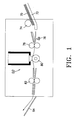
- FIG. 1 is a schematic view illustrating the configuration of a conventional ink-jet printer.
- the printer has a cassette 72 containing paper 70.
- Paper feed roller 74 for feeding paper 70 from the paper cassette 72, is installed above the leading edge of cassette 72.
- a sensor 76 for determining the paper feed state, is installed at one side of paper feed roller 74 to stop paper feed roller 74 and start transfer roller 78.
- a transfer roller 78 is installed beside sensor 76, and is used to transfer the paper 70 to a cartridge 50 containing a printing head 54.
- a rectangular shaped cartridge 50 which undergoes a rectilinear reciprocating motion driven by a drive motor, is installed beside transfer roller 78.
- a platen roller 80 is installed below cartridge 50 and transfers paper 70 while printing using heat.
- a paper discharge roller 82 is installed near the platen roller 80 to discharge the printed paper to stacker 84.
- cartridge 50 consists of ink container 51, for storing ink 38, and head 54, for printing images on paper 70 according to electric signals from a control unit.
- FIG. 3 illustrating the configuration of head 54, an ejection orifice 56, for ejecting ink 38, is formed in a plate 52, and a channel 58 connects with the ejection orifice 56 to provide ink 38 to the orifice.
- a heating element 62 is installed in the bottom of the channel 58 and heats and evaporates ink 38 to create vapour pressure.
- Electrodes 64 are installed on both sides of the heating element 62 to which they supply energy.
- a substrate layer 68, made of silicon and a resistor layer 66 for insulating the electrodes 64 are installed below the electrodes 64.
- a protective film 60 is formed on the electrodes 64 to protect the electrodes 64, the heating element 62 and the resistor layer 66 from corrosion and oxidation reactions with the ink.
- paper 70 in cassette 72 is transferred by paper feed roller 74 and activates sensor 76.
- Paper feed roller 74 stops after a specified period of time based on the distance to transfer roller 78.
- the paper is fed to cartridge 50 by transfer roller 78.
- Cartridge 50 prints while transferring the paper at a speed calculated from a step which is the distance between the paper and transfer roller 78.
- Electrodes 64 As shown in FIG. 3, once the control unit sends a print command to head 54, voltage is applied to electrodes 64. Heating element 62 is heated by electrodes 64, so that ink in close proximity is evaporated, and a bubble is created. Ink in channel 58 is sprayed onto the paper through ejection orifice 56 by vapour pressure, thus forming the desired letters or pictures. Platen roller 80 fixes the image to the paper using a high voltage between 500 and 5000V. The paper is then transferred to stacker 84 by paper discharge roller 82, ending the printing process.
- head 54 is installed in a serial matrix configuration and prints while following a rectilinear reciprocating motion.
- the operation of such a head requires high technology to control the reciprocating motor to maintain resolutions exceeding 300 dots per inch (dpi) and precise transference of head 54 as well as a mechanism for the rectilinear reciprocating motion of head 54.
- Serial heads following a rectilinear reciprocating motion are limited in printing speed. Special mechanisms must be installed to increase printing speed, but this makes the products very large and bulky.
- An objective of the present invention is to create an ink-jet printing device which is capable of producing resolution exceeding 300dpi as the head rotates.
- Another objective of the present invention is to provide an ink-jet printing device of increased printing speed.
- an ink-jet printing device comprising:
- the ink-jet printing device preferably further comprises a paper feed roller for feeding paper from a paper cassette; a sensor for detecting paper fed by the feed roller; a transfer roller for feeding the paper into a paper feed path upon detection by the sensor; and a paper discharge roller for transferring the printed paper to a stacker.
- the ink-jet printing device may further comprise a platen roller for fixing the image onto the paper and provided on the opposite side of the feed path from the ink cartridge.
- the rows of heads may be aligned parallel to the axis of the ink cartridge, but re preferably helically arranged on the surface of the ink cartridge.
- the said rows of heads are alternately arranged on the ink cartridge, forming a chequer-board pattern.
- Each head may comprises a heater chip for heating the ink and a nozzle plate for ejecting the ink onto the paper.
- a heater chip for heating the ink
- a nozzle plate for ejecting the ink onto the paper.
- it may comprise:
- Two or more ejection orifices may be formed in each nozzle plate.
- the printer has a cassette 72 containing paper 70.
- a paper feed roller 74 for feeding the paper in cassette 72 is installed above the leading edge of cassette 72.
- a sensor 76 for sensing the paper feed state is installed beside the paper feed roller 74 to determine when to stop the paper feed roller 74 and start the transfer roller 78.
- the transfer roller 78 is installed beside sensor 76 to transfer the paper 70 to a drum cartridge 10 with head 54.
- the cylindrical drum cartridge 10, which rotates on shaft 16, is installed beside the transfer roller 78.
- Platen roller 80 is installed under the drum cartridge 10 to fix an image to the paper with a high voltage while transferring the paper.
- Paper discharge roller 82 is installed beside platen roller 80 to transfer the printed paper to stacker 84.
- the surface of the drum cartridge 10 has heads 40 which print images on the paper based upon electric signals from the control unit while the cartridge rotates on shaft 16.
- heads 40 are arranged forming a spiral helix about the shaft with a specified angle creating a chequer-board pattern.
- the lines of heads could be parallel to the axis of the cartridge, and in that case skewing of the image could be reduced by using a line buffer to store the data for a line of printing and sending the data to the heads simultaneously.
- Head 40 consists of heater chip 18, for heating ink 38, and nozzle plate 14, for ejecting ink 38 to the paper.
- the head 40 includes a nozzle plate 14 with ejection orifices 30 for ejecting the bubble 34 of ink 38 onto the paper as a form of a drop 32 and a channel 36 which is connected to ejection orifices 30 to introduce ink 38 in form of bubble 34.
- Two or more ejection orifices 30 are formed in the nozzle plate 10 to increase the print speed.
- Resistor portions 24 are installed at one side of channel 36 to create vapour pressure and bubbles 34 by heating ink 38.
- First and second electrodes 22 and 23 are installed on both sides of each resistor portion 24 to heat the resistor portion 24 by applying a specified voltage.
- Slot 28, between resistor portions 24, draws ink 38 toward the parts of the channel 36 where resistor units 24 are installed.
- the first and second electrodes, 22 and 26, and resistor portions 24 are installed on substrate layer 12, which is made of silicon.
- the chamber 20 is created inside substrate layer 12.
- ink-jet printer with the drum type head having such structure is as follows. As shown in FIG. 4, once the printer is switched "on" responding to an initial signal, paper 70 in cassette 72 is transferred by paper feed roller 74 and activates sensor 76. Paper feed roller 74 stops after a specified period of time based on the distance from transfer roller 78. The paper is transferred to drum cartridge 10 by transfer roller 78. Drum cartridge 10 starts printing on the paper while rotating in the specified direction. As shown in FIG. 7, once the control unit sends a print command to head 40, first and second electrodes 22 and 26 are provided with voltage and heat resistor portions 24. At the same time, ink 38 stored in chamber 20 flows into channel 36 through slot 28. Ink 38, near resistor portions 24 is evaporated and forms bubbles 34. Bubbles 34 of ink 38 are ejected onto the paper in the form of dots 32 through ejection orifices 30 connected to channel 36, thus forming letters or pictures.
- the platen roller 80 in FIG. 4 fixes the image to the paper with a high voltage between 500 and 5000V.
- the printed paper is transferred to stacker 84 by paper discharge roller 82, and the printing process ends.
- the ink-jet printer with the drum type head according to the present invention can produce resolution exceeding 300dpi because the head is installed in a rotating drum cartridge instead of a cartridge following a rectilinear reciprocating motion.
- the present invention also increases the print speed to between 5ppM and 20ppM by forming two or more ejection orifices in the head of the drum cartridge. Since the drum cartridge does not require a moving carriage to allow for rectilinear motion, the product can be miniaturized.
Abstract
Description
Claims (12)
- An ink-jet printing device comprising:a cylindrical drum-shaped ink cartridge;a plurality of rows of ink-jet heads formed on the ink cartridge, each including one or more ink ejection orifices, for printing an image onto paper while the ink cartridge rotates; anda control unit for controlling the operation of the ink-jet heads.
- An ink-jet printing device according to claim 1 further comprising a paper feed roller for feeding paper from a paper cassette.
- An ink-jet printing device according to claim 2 further comprising a sensor for detecting paper fed by the feed roller and a transfer roller for feeding the paper into a paper feed path upon detection by the sensor.
- An ink-jet printing device according to claim 3 further comprising a platen roller for fixing the image onto the paper and provided on the opposite side of the feed path from the ink cartridge.
- An ink-jet printing device according to any preceding claim further comprising a paper discharge roller for transferring the printed paper to a stacker.
- An ink-jet printing device according to any preceding claim in which the said rows of heads are aligned parallel to the axis of the ink cartridge.
- An ink-jet printing device according to any one of claims 1-5 in which the said rows of heads are helically arranged on the surface of the ink cartridge.
- An ink-jet printing device according to any preceding claim in which the said rows of heads are alternately arranged on the ink cartridge, forming a chequer-board pattern.
- An ink-jet printing device according to any preceding claim in which each head comprises a heater chip for heating the ink and a nozzle plate for ejecting the ink onto the paper.
- An ink-jet printing device according to claim 9 in which each head comprises:a resistor portion for heating the ink and creating vapour pressure, including first and second electrodes for providing the resistor portion with an applied voltage;a slot for transferring the ink from an ink chamber in the ink cartridge to the resistor portion; anda channel for transferring ink from the resistor portion to the ejection orifices.
- An ink-jet printing device according to claim 9 or claim 10 in which two or more ejection orifices are formed in each nozzle plate.
- An ink-jet printing device as described with reference to and as illustrated in FIGs. 4 et seq. of the accompanying drawings.
Applications Claiming Priority (2)
| Application Number | Priority Date | Filing Date | Title |
|---|---|---|---|
| KR4065196 | 1996-09-18 | ||
| KR1019960040651A KR100208378B1 (en) | 1996-09-18 | 1996-09-18 | Ink-jet printer apparatus of a drum type head |
Publications (3)
| Publication Number | Publication Date |
|---|---|
| EP0830944A2 true EP0830944A2 (en) | 1998-03-25 |
| EP0830944A3 EP0830944A3 (en) | 1999-03-03 |
| EP0830944B1 EP0830944B1 (en) | 2003-07-23 |
Family
ID=19474255
Family Applications (1)
| Application Number | Title | Priority Date | Filing Date |
|---|---|---|---|
| EP97307268A Expired - Lifetime EP0830944B1 (en) | 1996-09-18 | 1997-09-18 | Ink-jet printing device with drum head |
Country Status (5)
| Country | Link |
|---|---|
| US (1) | US6033053A (en) |
| EP (1) | EP0830944B1 (en) |
| JP (1) | JPH10100449A (en) |
| KR (1) | KR100208378B1 (en) |
| DE (1) | DE69723637T2 (en) |
Cited By (2)
| Publication number | Priority date | Publication date | Assignee | Title |
|---|---|---|---|---|
| EP1694507A2 (en) * | 2003-07-31 | 2006-08-30 | Nissim Einat | Ink jet printing method and apparatus |
| CN109070586A (en) * | 2016-06-28 | 2018-12-21 | 昭和铝罐株式会社 | Printing equipment, the manufacturing method of beverage tank, beverage tank and beverage can |
Families Citing this family (11)
| Publication number | Priority date | Publication date | Assignee | Title |
|---|---|---|---|---|
| US7059698B1 (en) | 2002-10-04 | 2006-06-13 | Lexmark International, Inc. | Method of altering an effective print resolution of an ink jet printer |
| US6786591B2 (en) * | 2002-10-24 | 2004-09-07 | Hewlett-Packard Development Company, L.P. | Fluid ejector apparatus and methods |
| US20040081689A1 (en) * | 2002-10-24 | 2004-04-29 | Dunfield John Stephen | Pharmaceutical dosage form and method of making |
| US7547092B2 (en) * | 2004-01-21 | 2009-06-16 | Silverbrook Research Pty Ltd | Method for facilitating the upgrade of an inkjet printer |
| US7240985B2 (en) * | 2005-01-21 | 2007-07-10 | Xerox Corporation | Ink jet printhead having two dimensional shuttle architecture |
| DE102006001223A1 (en) * | 2006-01-10 | 2007-07-12 | Khs Ag | Apparatus for printing on bottles or similar containers |
| JP2009202434A (en) | 2008-02-28 | 2009-09-10 | Seiko Epson Corp | Fluid jetting apparatus |
| KR100953495B1 (en) * | 2008-05-21 | 2010-04-16 | 건국대학교 산학협력단 | Method and Apparatus for Roll-To-Roll type Printing |
| US8001893B2 (en) * | 2008-08-06 | 2011-08-23 | Lexmark International, Inc. | Rotary inkjet imaging apparatus and method for printing on a stationary page of media in a curved configuration |
| US8162438B2 (en) * | 2008-12-31 | 2012-04-24 | Lexmark International, Inc. | Rotary printhead disc in a rotary inkjet imaging apparatus |
| KR20200058797A (en) | 2018-11-20 | 2020-05-28 | 현대자동차주식회사 | Oil pan drain device for vehicle |
Citations (9)
| Publication number | Priority date | Publication date | Assignee | Title |
|---|---|---|---|---|
| US3640214A (en) * | 1968-06-21 | 1972-02-08 | Precisa Ag | Selective printer employing inking spark discharge |
| JPS60972A (en) * | 1983-06-08 | 1985-01-07 | Nozaki Insatsu Shigyo Kk | Thermal head |
| US4785311A (en) * | 1986-01-30 | 1988-11-15 | Canon Kabushiki Kaisha | Recording head apparatus and method having pluralities of crossed electrodes |
| US4855768A (en) * | 1987-03-31 | 1989-08-08 | Minolta Camera Kabushiki Kaisha | Digital printing apparatus |
| JPH05147284A (en) * | 1991-11-30 | 1993-06-15 | Mita Ind Co Ltd | Ink jet recording apparatus |
| EP0556045A2 (en) * | 1992-02-12 | 1993-08-18 | Canon Kabushiki Kaisha | Image recording apparatus with improved conveying system for recording medium |
| JPH05261906A (en) * | 1992-03-19 | 1993-10-12 | Fujitsu Ltd | Rotating ink jet head |
| EP0600712A2 (en) * | 1992-11-30 | 1994-06-08 | Hewlett-Packard Company | Method and apparatus for ink transfer printing |
| WO1995029063A1 (en) * | 1994-04-20 | 1995-11-02 | OCé PRINTING SYSTEMS GMBH | Thermoelectric printing unit for transferring ink to a print carrier |
Family Cites Families (9)
| Publication number | Priority date | Publication date | Assignee | Title |
|---|---|---|---|---|
| JPS58220758A (en) * | 1982-06-16 | 1983-12-22 | Matsushita Electric Ind Co Ltd | Ink jet recorder |
| DE3331488A1 (en) * | 1982-09-01 | 1984-03-01 | Konishiroku Photo Industry Co., Ltd., Tokyo | HEAD PIECE FOR A PAINT SPRAY PRINTING DEVICE |
| US4580148A (en) * | 1985-02-19 | 1986-04-01 | Xerox Corporation | Thermal ink jet printer with droplet ejection by bubble collapse |
| US4714936A (en) * | 1985-06-24 | 1987-12-22 | Howtek, Inc. | Ink jet printer |
| EP0271090B1 (en) * | 1986-12-10 | 1994-08-31 | Canon Kabushiki Kaisha | Recording apparatus |
| US5465108A (en) * | 1991-06-21 | 1995-11-07 | Rohm Co., Ltd. | Ink jet print head and ink jet printer |
| JPH05124182A (en) * | 1991-11-01 | 1993-05-21 | Canon Inc | Ink-jet recorder |
| CA2078045C (en) * | 1992-09-11 | 1999-11-16 | Mark R. Sestak | Global management of telephone directory |
| US5322594A (en) * | 1993-07-20 | 1994-06-21 | Xerox Corporation | Manufacture of a one piece full width ink jet printing bar |
-
1996
- 1996-09-18 KR KR1019960040651A patent/KR100208378B1/en not_active IP Right Cessation
-
1997
- 1997-09-18 JP JP9253994A patent/JPH10100449A/en active Pending
- 1997-09-18 EP EP97307268A patent/EP0830944B1/en not_active Expired - Lifetime
- 1997-09-18 US US08/933,337 patent/US6033053A/en not_active Expired - Fee Related
- 1997-09-18 DE DE69723637T patent/DE69723637T2/en not_active Expired - Fee Related
Patent Citations (9)
| Publication number | Priority date | Publication date | Assignee | Title |
|---|---|---|---|---|
| US3640214A (en) * | 1968-06-21 | 1972-02-08 | Precisa Ag | Selective printer employing inking spark discharge |
| JPS60972A (en) * | 1983-06-08 | 1985-01-07 | Nozaki Insatsu Shigyo Kk | Thermal head |
| US4785311A (en) * | 1986-01-30 | 1988-11-15 | Canon Kabushiki Kaisha | Recording head apparatus and method having pluralities of crossed electrodes |
| US4855768A (en) * | 1987-03-31 | 1989-08-08 | Minolta Camera Kabushiki Kaisha | Digital printing apparatus |
| JPH05147284A (en) * | 1991-11-30 | 1993-06-15 | Mita Ind Co Ltd | Ink jet recording apparatus |
| EP0556045A2 (en) * | 1992-02-12 | 1993-08-18 | Canon Kabushiki Kaisha | Image recording apparatus with improved conveying system for recording medium |
| JPH05261906A (en) * | 1992-03-19 | 1993-10-12 | Fujitsu Ltd | Rotating ink jet head |
| EP0600712A2 (en) * | 1992-11-30 | 1994-06-08 | Hewlett-Packard Company | Method and apparatus for ink transfer printing |
| WO1995029063A1 (en) * | 1994-04-20 | 1995-11-02 | OCé PRINTING SYSTEMS GMBH | Thermoelectric printing unit for transferring ink to a print carrier |
Non-Patent Citations (3)
| Title |
|---|
| PATENT ABSTRACTS OF JAPAN vol. 009, no. 114 (M-380), 18 May 1985 & JP 60 000972 A (NOZAKI INSATSU SHIGIYOU KK), 7 January 1985 * |
| PATENT ABSTRACTS OF JAPAN vol. 017, no. 537 (M-1487), 28 September 1993 & JP 05 147284 A (MITA IND CO LTD), 15 June 1993 * |
| PATENT ABSTRACTS OF JAPAN vol. 018, no. 025 (M-1542), 14 January 1994 & JP 05 261906 A (FUJITSU LTD), 12 October 1993 * |
Cited By (4)
| Publication number | Priority date | Publication date | Assignee | Title |
|---|---|---|---|---|
| EP1694507A2 (en) * | 2003-07-31 | 2006-08-30 | Nissim Einat | Ink jet printing method and apparatus |
| EP1694507A4 (en) * | 2003-07-31 | 2010-01-06 | Nissim Einat | Ink jet printing method and apparatus |
| US7922299B2 (en) | 2003-07-31 | 2011-04-12 | Moshe Einat | Ink jet printing method and apparatus |
| CN109070586A (en) * | 2016-06-28 | 2018-12-21 | 昭和铝罐株式会社 | Printing equipment, the manufacturing method of beverage tank, beverage tank and beverage can |
Also Published As
| Publication number | Publication date |
|---|---|
| KR19980021706A (en) | 1998-06-25 |
| JPH10100449A (en) | 1998-04-21 |
| DE69723637T2 (en) | 2004-04-15 |
| EP0830944B1 (en) | 2003-07-23 |
| KR100208378B1 (en) | 1999-07-15 |
| US6033053A (en) | 2000-03-07 |
| EP0830944A3 (en) | 1999-03-03 |
| DE69723637D1 (en) | 2003-08-28 |
Similar Documents
| Publication | Publication Date | Title |
|---|---|---|
| US6234605B1 (en) | Multiple resolution pagewidth ink jet printer including a positionable pagewidth printbear | |
| EP0830944B1 (en) | Ink-jet printing device with drum head | |
| US6048059A (en) | Variable power preheater for an ink printer | |
| EP0390473B1 (en) | An ink jet recording apparatus | |
| EP0443801B1 (en) | Liquid discharging recording head | |
| US5252992A (en) | Ink jet recording apparatus | |
| JPH05185680A (en) | Recorder | |
| US6497468B1 (en) | Printing apparatus, and method for controlling the power of the printing apparatus | |
| JPH05185661A (en) | Recording apparatus | |
| JPH07323615A (en) | Recording apparatus | |
| JP2931386B2 (en) | Ink jet recording apparatus and method | |
| JP4585660B2 (en) | Inkjet printing apparatus and inkjet printing method | |
| JPH0516370A (en) | Image recorder | |
| JP3233368B2 (en) | Recording device | |
| JP2810476B2 (en) | Recording apparatus and control method for recording apparatus | |
| JP2005177989A (en) | Inkjet recording apparatus and inkjet recording method | |
| JP4104512B2 (en) | Image forming apparatus | |
| JP3320141B2 (en) | Recording device | |
| JP2750933B2 (en) | Recording device | |
| JPH04368877A (en) | Image forming apparatus | |
| JP3244752B2 (en) | Image forming device | |
| JPH07256943A (en) | Device for input and output of information | |
| JPH0538853A (en) | Recording apparatus | |
| JP2882678B2 (en) | Image recording device | |
| JPH06134997A (en) | Ink jet recorder |
Legal Events
| Date | Code | Title | Description |
|---|---|---|---|
| PUAI | Public reference made under article 153(3) epc to a published international application that has entered the european phase |
Free format text: ORIGINAL CODE: 0009012 |
|
| 17P | Request for examination filed |
Effective date: 19971001 |
|
| AK | Designated contracting states |
Kind code of ref document: A2 Designated state(s): DE FR GB |
|
| PUAL | Search report despatched |
Free format text: ORIGINAL CODE: 0009013 |
|
| AK | Designated contracting states |
Kind code of ref document: A3 Designated state(s): AT BE CH DE DK ES FI FR GB GR IE IT LI LU MC NL PT SE |
|
| RIN1 | Information on inventor provided before grant (corrected) |
Inventor name: EUN, JONG-MOON,C/O SAMSUNG ELECTRONICS CO. LTD. |
|
| AKX | Designation fees paid |
Free format text: DE FR GB |
|
| 17Q | First examination report despatched |
Effective date: 20010315 |
|
| GRAH | Despatch of communication of intention to grant a patent |
Free format text: ORIGINAL CODE: EPIDOS IGRA |
|
| GRAH | Despatch of communication of intention to grant a patent |
Free format text: ORIGINAL CODE: EPIDOS IGRA |
|
| GRAH | Despatch of communication of intention to grant a patent |
Free format text: ORIGINAL CODE: EPIDOS IGRA |
|
| GRAA | (expected) grant |
Free format text: ORIGINAL CODE: 0009210 |
|
| AK | Designated contracting states |
Designated state(s): DE FR GB |
|
| REG | Reference to a national code |
Ref country code: GB Ref legal event code: FG4D |
|
| REF | Corresponds to: |
Ref document number: 69723637 Country of ref document: DE Date of ref document: 20030828 Kind code of ref document: P |
|
| ET | Fr: translation filed | ||
| PLBE | No opposition filed within time limit |
Free format text: ORIGINAL CODE: 0009261 |
|
| STAA | Information on the status of an ep patent application or granted ep patent |
Free format text: STATUS: NO OPPOSITION FILED WITHIN TIME LIMIT |
|
| 26N | No opposition filed |
Effective date: 20040426 |
|
| PGFP | Annual fee paid to national office [announced via postgrant information from national office to epo] |
Ref country code: DE Payment date: 20070913 Year of fee payment: 11 |
|
| PGFP | Annual fee paid to national office [announced via postgrant information from national office to epo] |
Ref country code: GB Payment date: 20070912 Year of fee payment: 11 |
|
| PGFP | Annual fee paid to national office [announced via postgrant information from national office to epo] |
Ref country code: FR Payment date: 20070914 Year of fee payment: 11 |
|
| GBPC | Gb: european patent ceased through non-payment of renewal fee |
Effective date: 20080918 |
|
| REG | Reference to a national code |
Ref country code: FR Ref legal event code: ST Effective date: 20090529 |
|
| PG25 | Lapsed in a contracting state [announced via postgrant information from national office to epo] |
Ref country code: DE Free format text: LAPSE BECAUSE OF NON-PAYMENT OF DUE FEES Effective date: 20090401 |
|
| PG25 | Lapsed in a contracting state [announced via postgrant information from national office to epo] |
Ref country code: FR Free format text: LAPSE BECAUSE OF NON-PAYMENT OF DUE FEES Effective date: 20080930 |
|
| PG25 | Lapsed in a contracting state [announced via postgrant information from national office to epo] |
Ref country code: GB Free format text: LAPSE BECAUSE OF NON-PAYMENT OF DUE FEES Effective date: 20080918 |