EP0830677B1 - Electronic computer having an optical disc - Google Patents
Electronic computer having an optical disc Download PDFInfo
- Publication number
- EP0830677B1 EP0830677B1 EP96914389A EP96914389A EP0830677B1 EP 0830677 B1 EP0830677 B1 EP 0830677B1 EP 96914389 A EP96914389 A EP 96914389A EP 96914389 A EP96914389 A EP 96914389A EP 0830677 B1 EP0830677 B1 EP 0830677B1
- Authority
- EP
- European Patent Office
- Prior art keywords
- cpu
- electronic computer
- unit
- data
- type
- Prior art date
- Legal status (The legal status is an assumption and is not a legal conclusion. Google has not performed a legal analysis and makes no representation as to the accuracy of the status listed.)
- Expired - Lifetime
Links
Images


Classifications
-
- G—PHYSICS
- G11—INFORMATION STORAGE
- G11B—INFORMATION STORAGE BASED ON RELATIVE MOVEMENT BETWEEN RECORD CARRIER AND TRANSDUCER
- G11B31/00—Arrangements for the associated working of recording or reproducing apparatus with related apparatus
-
- G—PHYSICS
- G11—INFORMATION STORAGE
- G11B—INFORMATION STORAGE BASED ON RELATIVE MOVEMENT BETWEEN RECORD CARRIER AND TRANSDUCER
- G11B19/00—Driving, starting, stopping record carriers not specifically of filamentary or web form, or of supports therefor; Control thereof; Control of operating function ; Driving both disc and head
- G11B19/02—Control of operating function, e.g. switching from recording to reproducing
- G11B19/06—Control of operating function, e.g. switching from recording to reproducing by counting or timing of machine operations
-
- G—PHYSICS
- G11—INFORMATION STORAGE
- G11B—INFORMATION STORAGE BASED ON RELATIVE MOVEMENT BETWEEN RECORD CARRIER AND TRANSDUCER
- G11B19/00—Driving, starting, stopping record carriers not specifically of filamentary or web form, or of supports therefor; Control thereof; Control of operating function ; Driving both disc and head
- G11B19/02—Control of operating function, e.g. switching from recording to reproducing
- G11B19/12—Control of operating function, e.g. switching from recording to reproducing by sensing distinguishing features of or on records, e.g. diameter end mark
Definitions
- This invention refers to an electronic computer for handling magnetooptic media, comprising a compact disk (CD) reading unit for reading data pre-recorded on a removable disk of different type (AUDIO-CD, PHOTO-CD, VIDEO-CD), a central processing unit (CPU) connected to the CD reading unit for recognising the type of removable disk inserted in the CD reading unit, memory means connected to the CPU for storing data and programs, input receiving means connected to the CPU for receiving input from an external input unit, and connecting means for connecting a display unit to the CPU in order to playback said pre-recorded data. More precisely, this invention refers to an electronic computer for handling optical type compact disks (CD-ROM).
- CD-ROM compact disks
- Personal computers are known in the current art that are used to read and playback optic and/or magnetic media. These computers, one of which is the Applicant's PCS Educator, use either a keyboard or a pointing device, commonly known as a “mouse", to activate the read and playback functionality of the CD-ROM and have the Personal Computer's monitor as their visual display device.
- a keyboard or a pointing device commonly known as a “mouse”
- CD-players also known in the current art is the use of commercial appliances, known as CD-players, to read and playback CD-ROM's. These appliances provide for actuation of the various controls by means of a plurality of pushbuttons, each with a predefined functionality, and have a television set as their visual display device.
- a CD-player for playing CD-audio and memory disk which comprises a system controller, having a microcomputer, for controlling the entire system, an operating section, for issuing various commands in response to the user's key entries, and an image display controller, associated to a Liquid Crystal Display, for displaying images, such as a map.
- Such CD-player is able to determine whether the disk to be played is a CD-audio or a memory disk on the basis of identifying information in the TOC (Table Of Contents) of the disk.
- the known computers though they allow reading and playing of CD-ROMs, are of limited performance with respect to the commercial CD-players insofar as they are not apt for reading and playback of all the types of CD-ROM available on the market, nor for use of the television as the preferential visual display device, nor for connection to other magnetic media playback devices, such as video recorders for example. Further, the known computers are difficult for non-expert users to use as they require utilisation of devices, such as the keyboard or mouse, with which domestic users are unfamiliar.
- CD-players are easy to use, they can only read and playback CD-ROMs and cannot perform any other processing work.
- these devices have the drawback that they are not upgradable, so that their performance cannot be improved upon nor can their characteristics be enhanced, for example following introduction of a new type CD-ROM.
- the electronic computer is characterised by a console having a plurality of actuating elements selectively actuatable for generating command signals, and by control means connected to the plurality of actuating elements, and to the CPU; wherein the CPU is able to recognise the type of removable disk inserted in the CD reading unit by comparing the data read from the removable disk with the data stored into the memory means and to transmit to the control means I/O signals indicative of the type of removable disk inserted, and wherein the control means is able to enable the actuating elements to transmit the command signals to the CPU for commanding the functions (Play,Pause,Stop,FF,etc.) of the CD reading unit on the basis of predefined programs stored into said memory means.
- the electronic computer is characterised by the fact that it has automatic means for the control of its electric power supply, which are suitable for generating, after a predetermined time or following depression of a given push-button, a switching signal that results in switching from a operating state of full performance, accompanied by a greater consumption of electricity, to a stand-by state of operation where less electricity is consumed.
- the electronic computer is provided with communication means that may be controlled by the central processing unit and can be connected to a television or to a video recorder unit to visualise the contents of the CD-ROMs or the data processed by the computer on the television and/or to record the above-mentioned contents or data on the video recorder.
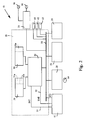
- an electronic computer 10 comprises a motherboard 20, a reader 21 for magneto-optic disks (CD-ROM) 14, a console 11, a speaker device 22 and a hard disk type memory unit (HDU) 23.
- a motherboard 20 a reader 21 for magneto-optic disks (CD-ROM) 14
- a console 11 a speaker device 22
- a hard disk type memory unit (HDU) 23 a hard disk type memory unit
- Electronic computer 10 further comprises a video interface logic (SCART controller) 35 and a series of known type connection sockets 61, 62 and 63, apt to be connected respectively to a keyboard, a mouse and a monitor, not shown on the drawings.
- SCART controller video interface logic
- Reader 21, console 11, speaker 22, HDU 23, SCART controller 35 and the series of sockets 61, 62 and 63 are connected to a data channel 33 of motherboard 20.
- Motherboard 20 comprises a central processing unit (CPU) 30 and both a random access memory (RAM) 32 and a read only memory (ROM) 31, both connected to CPU 30.
- CPU central processing unit
- RAM random access memory
- ROM read only memory
- Motherboard 20 may be comprised, for example, of a motherboard for Personal Computer and is suitable for processing programs recorded on HDU 23 and reading, through reader 21, data pre-recorded on CD-ROMs 14, which may be of the AUDIO, PHOTO, VIDEO or DATA types.
- Reader 21 comprises a slot 19 in which CD-ROMs 14 are capable of being removably inserted.
- Console 11 comprises a display unit 47 suitable for the display of messages and a button panel 45, having a plurality of pushbuttons 48 suitable to be activated to transmit predefined commands to the CPU 30, either along data channel 33 or through two lines 51 and 52.
- SCART controller 35 is apt to be connected to a television set 12 and a video recorder 13, both known in the current art, by means respectively of SCART plugs (16 and 18) and cables (15 and 17) and is apt to transmit the data read by reader 21 to television set 12 and/or video-recorder 13 for playback.
- SCART controller 35 is also apt to transmit, in a known way, audio and video signals from video recorder 13 to television set 12.
- ROM 31 is suitable for storing the firmware programs, developed during the design stage of motherboard 20, and comprises two areas (31a and 31b) in which the instructions are stored that cause electronic computer 10 to execute given functions that will be described later in detail.
- RAM 32 comprises an area 32a in which information from the CD-ROM inserted in reader 21 is apt to be stored, as will be described later in detail.
- CPU 30 which is constituted, for example, by a 486SL microprocessor produced by INTEL Inc., is suitable for supporting a protected type system management feature called "Protect and System Management Mode", already described in Patent Application No. TO95A000122, filed on 21st February 1995 by the Applicant.
- This feature is originated by a System Management Interrupt signal, hereinafter simply "SMI", and is characterised by the fact that CPU 30, once it receives the SMI signal, suspends current activity, handles the instructions provided for in the motherboard 20 design stage and stored in ROM 31 concerning the SMI signal received, before returning to regular activity as if the interrupt had never happened.
- SMI System Management Interrupt signal
- Console 11 comprises a microchip 40 (Fig. 3) to which button panel 45, display 47 and a light-emitting diode (LED) 46 are connected.
- Microchip 40 is constituted, for example, by the 75268 MICROCHIP produced by Nippon Electric Corporation and comprises a central processing unit (CPU) 43, a read only memory (ROM) 41, suitable for recording programs developed in the console 11 design stage, and a random access memory (RAM) 42.
- CPU central processing unit
- ROM read only memory
- RAM random access memory
- Console 11 is suitable for transmitting CPU 30, through line 52, the SMI signal and consequently institute Protect and System Management Mode.
- Console 11 is also suitable for transmitting, through line 51, an interrupt signal INT causing CPU 30 to suspend, in a known way, its activity in expectation of input/output data (I/O) directed by console 11 to data channel 33.
- an interrupt signal INT causing CPU 30 to suspend, in a known way, its activity in expectation of input/output data (I/O) directed by console 11 to data channel 33.
- Button panel 45 comprises a plurality of function buttons 48, such as "PLAY”, “PAUSE”, “FAST FORWARD”, “REWIND” and “STOP” commonly used on commercial type appliances, video recorders and CD-players for example, and is suitable for transmitting predefined signals to microchip 40, preferably by depressing one or more pushbuttons 48 in combination.
- One button 49 of button panel 45 (stand-by button) is suitable for transmitting the SMI signal to motherboard 20.
- CD-ROMs are formatted in such a way as to include a "Lead-in area" in which the table of contents (TOC) is stored, containing the number of tracks used, total playing time and, for each track, both the type of information recorded and the address of the track on the CD-ROM.
- TOC table of contents
- VTOC indications are recorded on the CD-ROM Directory structure, such as an index, names and dimensions of the data files. These indications are not featured on the CD-AUDIO media.
- CD-ROMs The specifications concerning data formatting on the CD-ROMs are described in standard manuals, named after the colour of the cover; for example, the CD-AUDIO specifications are described in the RED-BOOK, the DATA CD-ROM specfications are described in the YELLOW-BOOK, and so on.
- reader 21 sets CD-ROM 14 in rotation in a known way, reads the TOC area (Table Of Contents) and VTOC area (Volume Table Of Contents), if present, of CD-ROM 14 and transmits CPU 30 a message suitable for signalling that insertion has been made.
- CPU 30 interprets the message received and transfers the data read by reader 21 to area 32a of RAM 32.
- the data transferred to area 32a of RAM 32 are then compared with those stored in area 31a of ROM 31 in order to identify the type of CD-ROM 14 inserted.
- CPU 30 transmits console 11, through data channel 33, I/O signals indicating what type of CD-ROM 14 has been inserted and other related information.
- Microchip 40 upon reception of the I/O signals from CPU 30, drives display 47 so that messages corresponding to the type of CD-ROM 14 inserted in reader 21 are displayed and enables button panel 45 to enter commands in order to activate playback of the CD-ROM 14 inserted.
- AUDIO-CD OPERATING CONDITIONS MESSAGE DISPLAYED : On recognition of the CD CD AUDIO TOTAL TIME (MM:SS) TRACK (nnn) After recognition of the CD TRACK (nnn) CD AUDIO Play > TRACK (nnn) TIME (MM:SS) Pause TRACK (nnn) TIME (MM:SS) Stop TRACK CD AUDIO FF TRACK (nnn) > > TIME (MM:SS) RW TRACK (nnn) ⁇ ⁇ TIME (MM:SS) FF Scan SCAN > > TRACK (nnn) RW Scan SCAN ⁇ ⁇ TRACK (nnn) PHOTO CD OPERATING CONDITIONS : MESSAGE DISPLAYED : On recognition of the CD PHOTO CD PICTURE (nnn) Play/Autoplay P
- a predefined signal is transmitted to microchip 40 where it is interpreted by CPU 43, on the basis of the settings recorded in the ROM 41 design stage, and converted into an interrupt signal INT for transmission to CPU 30 (Fig. 2), through line 51, and into an I/O signal for transmission to data channel 33 of motherboard 20.
- CPU 30 thus commands reading and playback of CD-ROM 14 on the basis of predefined programs, memorised in RAM 32.
- the data read by the reader 21 are processed and transferred in a known way, through data channel 33, to speakers 22 for amplification and playback.
- the data read are processed and transferred in a known way to SCART controller 35 which, depending on the user-defined parameters stored in RAM 32, transmits the data to television 12, through socket 16 and cable 15 (Fig. 1), and/or to video recorder 13 through socket 18 and cable 17.
- CD-ROM 14 is VIDEO CD type
- the data read are processed and transferred in a known way to SCART controller 35 (Fig. 2) and to speakers 22 for playback.
- electronic computer 10 described up to here is suitable for recognising in an automatic way the type of magneto-optic medium 14 inserted in the reader 21 and for arranging for playback of the media 14 simply through depression of buttons 48 (Fig. 4).
- CPU 43 (Fig. 3) transmits the SMI signal to CPU 30 (Fig. 2).
- CPU 30 on receiving said signal, reads the predefined instructions in area 31b of ROM 31 and transmits, through data channel 33, commands suitable for suspending the activities of the peripheral units connected to motherboard 20 such as, for example, reader 21 and HDU 23.
- CPU 30 also transmits I/O signals to microchip 40 (Fig. 3) commanding LED 46 to light (Fig. 4), indicating the inoperative state of electronic computer 10 (Fig. 2).
- electronic computer 10 automatically goes into a condition of reduced activity or stand-by during which the consumption of electrical energy is greatly reduced.
- buttons 48 Only depression of a button 48 (Fig. 4) on button panel 45 or insertion of a new CD-ROM 14 in slot 19 (Fig. 1) can restore normal operating conditions.
- a signal is transmitted to microchip 40 that can send the SMI signal to CPU 30 (Fig. 2) which, having read the predefined instructions in area 31b of ROM 31, activates the peripheral units previously de-activated.
- CPU 43 In parallel with signal SMI, CPU 43 also transmits an interrupt signal INT along line 51 and a corresponding I/O signal to data channel 33 (Fig. 2) which make CPU 30 execute the function corresponding to the button 48 (Fig. 1) actuated. Activation and de-activation of electronic computer 10 may be achieved in a similar manner to the above through depression of stand-by button 49 (Fig. 3) which is apt to transmit the SMI signal to CPU 30 by means of microchip 40 (Fig. 2).
- button panel 45 instead of being fitted on the computer basic structure, may be provided on a freestanding remote control device and be suitable, in this case, for transmitting remotely the signals corresponding to the predefined functions of button panel 45.
- electronic computer 10 can be connected by means of connectors 61 and 62 to a keyboard and a known type of mouse commonly used in Personal Computers so that electronic computer 10 may be used as a common personal computer. In this form of use, it will be clear that both the buttons depressed and the processed data displayed by television 12 may be recorded by video recorder 13.
- electronic computer 10 can be connected by means of connector 63 to a known type monitor, commonly used in Personal Computers.
- a known type monitor commonly used in Personal Computers.
- both images recorded on PHOTO-CD or VIDEO-CD type CD-ROMs 14 and film clips read with video recorder 13 may be played back on this monitor, without the need for television 12.
Description
| AUDIO-CD | |
| OPERATING CONDITIONS : | MESSAGE DISPLAYED : |
| On recognition of the CD | CD AUDIO |
| TOTAL TIME (MM:SS) | |
| TRACK (nnn) | |
| After recognition of the CD | TRACK (nnn) |
| CD AUDIO | |
| Play | > |
| TRACK (nnn) | |
| TIME (MM:SS) | |
| Pause | |
| TRACK (nnn) | |
| TIME (MM:SS) | |
| Stop | TRACK |
| CD AUDIO | |
| FF | TRACK (nnn) |
| > > | |
| TIME (MM:SS) | |
| RW | TRACK (nnn) |
| < < | |
| TIME (MM:SS) | |
| FF Scan | SCAN |
| > > | |
| TRACK (nnn) | |
| RW Scan | SCAN |
| < < | |
| TRACK (nnn) |
| PHOTO CD | |
| OPERATING CONDITIONS : | MESSAGE DISPLAYED : |
| On recognition of the CD | PHOTO CD |
| PICTURE (nnn) | |
| Play/Autoplay | PICTURE (nnn) |
| NEXT (nnn+1) | |
| Autoplay button blinking | |
| Pause | || |
| PICTURE (nnn) | |
| NEXT (nnn+1) | |
| Stop | |
| FF | > > |
| PICTURE (nnn) | |
| NEXT (nnn+1) | |
| RW | < < |
| PICTURE (nnn) | |
| NEXT (nnn+1) |
| VIDEO CD | |
| OPERATING CONDITIONS : | MESSAGE DISPLAYED : |
| On recognition of the CD | VIDEO CD |
| TOTAL TIME (MM:SS) | |
| Play | > |
| (MM:SS) | |
| Pause | || |
| (MM:SS) | |
| Stop | VIDEO CD |
| FF | > > |
| (MM:SS) | |
| RW | < < |
| (MM:SS) |
Claims (7)
- An electronic computer (10) comprising a compact disk (CD) reading unit (21) for reading data pre-recorded on a removable disk (14) of different type (AUDIO-CD, PHOTO-CD, VIDEO-CD), a central processing unit (CPU) (30) connected to said CD readinq unit (21) for recognising the type of removable disk (14) inserted in said CD reading unit (21), memory means (31, 32) connected to said CPU (30) for storing data and programs, input receiving means (61) connected to said CPU (30) for receiving input from an external input unit and connecting means (16,18,35) for connecting a display unit (12) to said CPU (30) in order to playback said pre-recorded data, characterised by a console (11) having a plurality of actuating elements (48,49) selectively actuatable for generating command signals, and by control means (40) connected to said plurality of actuating elements (48,49), and to said CPU (30); wherein said CPU (30) is able to recognise the type of removable disk (14) inserted in said CD reading unit (21) by comparing the data read from said removable disk (14) with the data stored into said memory means (31,32) and to transmit to said control means (40) I/O signals indicative of the type of removable disk (14) inserted, and wherein said control means (40) controls said actuating elements (48,49) to transmit said command signals to said CPU (30) for commanding the functions (Play,Pause,Stop,FF,etc.) of said CD reading unit (21) on the basis of predefined programs stored into said memory means (31,32).
- An electronic computer (10) according to claim 1, characterised by display means (46. 47) connected to said control means (40), wherein said control means (40) controls said display means (46, 47) to display information relating to the type of removable disk (14) inserted.
- An electronic computer (10) according to claim 2, characterised in that said console (11) further comprises said display means (46,47).
- An electronic computer (10) according to claim 1 characterised in that said display unit (12) is a television.
- An electronic computer (10) according to claim 1 characterised in that said connecting means (16,18,35) is further connectable to a video reader/recorder unit (13) either for displaying on said display unit (12) data read from said video reader/recorder unit (13) or for recording on said video reader/recorder unit (13) said pre-recorded data and/or data processed by said CPU (30).
- An electronic computer (10) according to claim 1, characterised in that at least one (49) of said actuating elements (48,49) is actuatable for switching said CPU (30) from a full performance operating state to a reduced performance operating state (stand-by) and viceversa.
- An electronic computer (10) according to claim 1, characterised in that said console (11) further comprises means for remotely connecting said actuating elements (48,49) to said control means (40).
Applications Claiming Priority (3)
| Application Number | Priority Date | Filing Date | Title |
|---|---|---|---|
| ITTO950434 | 1995-05-29 | ||
| IT95TO000434A IT1279754B1 (en) | 1995-05-29 | 1995-05-29 | ELECTRONIC PROCESSOR WITH A UNIT FOR THE TREATMENT OF MAGNETO-OPTICAL SUPPORTS |
| PCT/IT1996/000101 WO1996038841A1 (en) | 1995-05-29 | 1996-05-17 | Electronic computer having a magneto-optic unit |
Publications (2)
| Publication Number | Publication Date |
|---|---|
| EP0830677A1 EP0830677A1 (en) | 1998-03-25 |
| EP0830677B1 true EP0830677B1 (en) | 1999-02-03 |
Family
ID=11413598
Family Applications (1)
| Application Number | Title | Priority Date | Filing Date |
|---|---|---|---|
| EP96914389A Expired - Lifetime EP0830677B1 (en) | 1995-05-29 | 1996-05-17 | Electronic computer having an optical disc |
Country Status (6)
| Country | Link |
|---|---|
| US (1) | US6047223A (en) |
| EP (1) | EP0830677B1 (en) |
| AU (1) | AU5777996A (en) |
| DE (1) | DE69601502T2 (en) |
| IT (1) | IT1279754B1 (en) |
| WO (1) | WO1996038841A1 (en) |
Families Citing this family (12)
| Publication number | Priority date | Publication date | Assignee | Title |
|---|---|---|---|---|
| US6226237B1 (en) | 1998-03-26 | 2001-05-01 | O2 Micro International Ltd. | Low power CD-ROM player for portable computer |
| US6895448B2 (en) * | 1998-03-26 | 2005-05-17 | O2 Micro, Inc. | Low-power audio CD player for portable computers |
| US6675233B1 (en) * | 1998-03-26 | 2004-01-06 | O2 Micro International Limited | Audio controller for portable electronic devices |
| US6954804B2 (en) * | 1998-03-26 | 2005-10-11 | Micro, Inc. | Controller for portable electronic devices |
| US7130930B1 (en) * | 2000-06-16 | 2006-10-31 | O2 Micro Inc. | Low power CD-ROM player with CD-ROM subsystem for portable computer capable of playing audio CDs without supply energy to CPU |
| US7818443B2 (en) * | 2000-12-01 | 2010-10-19 | O2Micro International Ltd. | Low power digital audio decoding/playing system for computing devices |
| US7890741B2 (en) * | 2000-12-01 | 2011-02-15 | O2Micro International Limited | Low power digital audio decoding/playing system for computing devices |
| US7522966B2 (en) * | 2000-12-01 | 2009-04-21 | O2Micro International Limited | Low power digital audio decoding/playing system for computing devices |
| US7526349B2 (en) * | 2000-12-01 | 2009-04-28 | O2Micro International Limited | Low power digital audio decoding/playing system for computing devices |
| US7522964B2 (en) | 2000-12-01 | 2009-04-21 | O2Micro International Limited | Low power digital audio decoding/playing system for computing devices |
| US7522965B2 (en) * | 2000-12-01 | 2009-04-21 | O2Micro International Limited | Low power digital audio decoding/playing system for computing devices |
| US6924667B2 (en) | 2002-07-19 | 2005-08-02 | O2Micro International Limited | Level shifting and level-shifting amplifier circuits |
Family Cites Families (9)
| Publication number | Priority date | Publication date | Assignee | Title |
|---|---|---|---|---|
| JPH06103578B2 (en) * | 1985-05-28 | 1994-12-14 | 松下電器産業株式会社 | Power control device for compact disk player |
| DE69116416T3 (en) * | 1990-04-17 | 2004-02-12 | Pioneer Electronic Corp. | Record player for a clay disc and a storage disc |
| JPH04236589A (en) * | 1991-01-18 | 1992-08-25 | Fujitsu Ltd | Data processing system provided with cd-rom drive |
| JPH05314624A (en) * | 1992-05-08 | 1993-11-26 | Pioneer Electron Corp | Information processing method for recording disk |
| US5500936A (en) * | 1993-03-12 | 1996-03-19 | Asymetrix Corporation | Multi-media slide presentation system with a moveable, tracked popup menu with button and title bars |
| JPH07288874A (en) * | 1994-04-14 | 1995-10-31 | Matsushita Electric Ind Co Ltd | Composite av equipment |
| US5835733A (en) * | 1994-12-22 | 1998-11-10 | Texas Instruments Incorporated | Method and apparatus for implementing a single DMA controller to perform DMA operations for devices on multiple buses in docking stations, notebook and desktop computer system |
| US5721951A (en) * | 1995-02-24 | 1998-02-24 | Digital Interactive Corporation Systems, Ltd. | Home entertainment system for playing software designed for play in home computer |
| KR0176510B1 (en) * | 1995-03-28 | 1999-04-15 | 윤종용 | Television compact disc player set with a selective signal processing function |
-
1995
- 1995-05-29 IT IT95TO000434A patent/IT1279754B1/en active IP Right Grant
-
1996
- 1996-05-17 DE DE69601502T patent/DE69601502T2/en not_active Expired - Lifetime
- 1996-05-17 US US08/973,165 patent/US6047223A/en not_active Expired - Lifetime
- 1996-05-17 AU AU57779/96A patent/AU5777996A/en not_active Abandoned
- 1996-05-17 WO PCT/IT1996/000101 patent/WO1996038841A1/en active IP Right Grant
- 1996-05-17 EP EP96914389A patent/EP0830677B1/en not_active Expired - Lifetime
Also Published As
| Publication number | Publication date |
|---|---|
| AU5777996A (en) | 1996-12-18 |
| ITTO950434A1 (en) | 1996-11-29 |
| ITTO950434A0 (en) | 1995-05-29 |
| EP0830677A1 (en) | 1998-03-25 |
| IT1279754B1 (en) | 1997-12-16 |
| US6047223A (en) | 2000-04-04 |
| DE69601502T2 (en) | 1999-08-26 |
| DE69601502D1 (en) | 1999-03-18 |
| WO1996038841A1 (en) | 1996-12-05 |
Similar Documents
| Publication | Publication Date | Title |
|---|---|---|
| US8116890B2 (en) | Portable sound reproducing system and method | |
| EP0830677B1 (en) | Electronic computer having an optical disc | |
| JP3106495B2 (en) | Home bus controller | |
| US5732059A (en) | Synchronous dubbing system and method thereof | |
| MY122857A (en) | Combination system and automatic copy method thereof | |
| US8380329B2 (en) | Controlling a digital audio player from a cassette tape player adapter | |
| US20070147778A1 (en) | Combination system and copy error preventing method thereof | |
| CN100385564C (en) | Composite system with mulitple reproducing device and method for controlling operation thereof | |
| KR20050054428A (en) | Versatile optical storage driving device for multimedia audio/video system | |
| JPS63168889A (en) | Information management system for magnetic tape file | |
| KR970006183B1 (en) | Ldp video accompaniment system | |
| KR0124386B1 (en) | Apparatus of displaying reproduction status of cdg in multidisc player | |
| JP2780369B2 (en) | Display device | |
| JPH0757444A (en) | Audio video system | |
| KR970001132Y1 (en) | Cd automatic reproduction apparatus for cd-i player | |
| KR100621283B1 (en) | Method for controlling operation of a portable set in a recharger | |
| KR970008615B1 (en) | Displaying method of disk and tape | |
| JP2000030013A (en) | Memory card recording and reproducing device | |
| KR20070064793A (en) | Apparatus and method for cutting down an electric power in av equipment | |
| KR20050122332A (en) | Apparatus for controlling power in a image displayer | |
| KR20040022015A (en) | Data reproducing apparatus for automatically recognizing a memory stick, and the method therefor | |
| JPH0411360A (en) | Data reproducing processor | |
| KR19990041386A (en) | How to prevent standby power consumption in video cassette recorders | |
| JP2003134437A (en) | Information recording device | |
| KR20040077134A (en) | Control method for recording mode of combo-system |
Legal Events
| Date | Code | Title | Description |
|---|---|---|---|
| PUAI | Public reference made under article 153(3) epc to a published international application that has entered the european phase |
Free format text: ORIGINAL CODE: 0009012 |
|
| 17P | Request for examination filed |
Effective date: 19971224 |
|
| AK | Designated contracting states |
Kind code of ref document: A1 Designated state(s): DE FR GB NL |
|
| GRAG | Despatch of communication of intention to grant |
Free format text: ORIGINAL CODE: EPIDOS AGRA |
|
| GRAG | Despatch of communication of intention to grant |
Free format text: ORIGINAL CODE: EPIDOS AGRA |
|
| GRAG | Despatch of communication of intention to grant |
Free format text: ORIGINAL CODE: EPIDOS AGRA |
|
| GRAH | Despatch of communication of intention to grant a patent |
Free format text: ORIGINAL CODE: EPIDOS IGRA |
|
| 17Q | First examination report despatched |
Effective date: 19980521 |
|
| GRAH | Despatch of communication of intention to grant a patent |
Free format text: ORIGINAL CODE: EPIDOS IGRA |
|
| GRAA | (expected) grant |
Free format text: ORIGINAL CODE: 0009210 |
|
| AK | Designated contracting states |
Kind code of ref document: B1 Designated state(s): DE FR GB NL |
|
| ET | Fr: translation filed | ||
| REF | Corresponds to: |
Ref document number: 69601502 Country of ref document: DE Date of ref document: 19990318 |
|
| PLBE | No opposition filed within time limit |
Free format text: ORIGINAL CODE: 0009261 |
|
| STAA | Information on the status of an ep patent application or granted ep patent |
Free format text: STATUS: NO OPPOSITION FILED WITHIN TIME LIMIT |
|
| 26N | No opposition filed | ||
| REG | Reference to a national code |
Ref country code: GB Ref legal event code: IF02 |
|
| REG | Reference to a national code |
Ref country code: DE Ref legal event code: R082 Ref document number: 69601502 Country of ref document: DE Representative=s name: WEICKMANN & WEICKMANN PATENTANWAELTE - RECHTSA, DE Ref country code: DE Ref legal event code: R082 Ref document number: 69601502 Country of ref document: DE Representative=s name: PATENTANWAELTE WEICKMANN & WEICKMANN, DE |
|
| REG | Reference to a national code |
Ref country code: FR Ref legal event code: PLFP Year of fee payment: 20 |
|
| PGFP | Annual fee paid to national office [announced via postgrant information from national office to epo] |
Ref country code: GB Payment date: 20150527 Year of fee payment: 20 Ref country code: DE Payment date: 20150528 Year of fee payment: 20 |
|
| PGFP | Annual fee paid to national office [announced via postgrant information from national office to epo] |
Ref country code: FR Payment date: 20150519 Year of fee payment: 20 Ref country code: NL Payment date: 20150526 Year of fee payment: 20 |
|
| REG | Reference to a national code |
Ref country code: DE Ref legal event code: R071 Ref document number: 69601502 Country of ref document: DE |
|
| REG | Reference to a national code |
Ref country code: NL Ref legal event code: MK Effective date: 20160516 |
|
| REG | Reference to a national code |
Ref country code: GB Ref legal event code: PE20 Expiry date: 20160516 |
|
| PG25 | Lapsed in a contracting state [announced via postgrant information from national office to epo] |
Ref country code: GB Free format text: LAPSE BECAUSE OF EXPIRATION OF PROTECTION Effective date: 20160516 |