EP0829812A2 - Method of designing an integrated circuit and integrated circuit designed by such method - Google Patents
Method of designing an integrated circuit and integrated circuit designed by such method Download PDFInfo
- Publication number
- EP0829812A2 EP0829812A2 EP97307084A EP97307084A EP0829812A2 EP 0829812 A2 EP0829812 A2 EP 0829812A2 EP 97307084 A EP97307084 A EP 97307084A EP 97307084 A EP97307084 A EP 97307084A EP 0829812 A2 EP0829812 A2 EP 0829812A2
- Authority
- EP
- European Patent Office
- Prior art keywords
- integrated circuit
- compiler
- optimiser
- hardware
- software
- Prior art date
- Legal status (The legal status is an assumption and is not a legal conclusion. Google has not performed a legal analysis and makes no representation as to the accuracy of the status listed.)
- Withdrawn
Links
Images


Classifications
-
- G—PHYSICS
- G06—COMPUTING; CALCULATING OR COUNTING
- G06F—ELECTRIC DIGITAL DATA PROCESSING
- G06F30/00—Computer-aided design [CAD]
- G06F30/30—Circuit design
Definitions
- the present invention relates to a method of designing an integrated circuit.
- the invention also relates to an integrated circuit designed by such a method.
- a design for a large scale integrated (LSI) circuit comprises a collection of gates, for instance for performing binary functions such as AND, OR, NOT, FLIP-FLOP, together with a specification of how the gates are to be interconnected.
- a layout tool may then be used to convert the design into a form suitable for fabrication in an appropriate technology.
- a known technique for producing such designs uses what is known as “schematic capture”.
- a graphical software tool allows a user to place each logical gate or collection of gates from a library and to interconnect the gates by "drawing" the wiring with a computer mouse.
- the resulting circuit may then be optimised, for instance by removing or simplifying gates without changing the total function of the circuit, and submitted for layout and fabrication.
- a designer has to consider the timing and logic for every or almost every gate or collection of gates so that this technique is difficult to use for large designs and is prone to error.
- HDL hardware description language
- Each statement in the HDL corresponds to several gates in the final design so that the input source code is relatively short compared with the logical complexity of the final design.
- the productivity of the designer may therefore be increased.
- Known HDLs include VHDL disclosed in IEEE Standard VHDL Language Reference Manual, IEEE Std 1076-1993, IEEE, New York, 1993, and Verilog disclosed by D.E. Thomas and P.R. Moorby in The Verilog Hardware Description Language, Kluwer Academic 1995.
- Such languages may be used with an appropriate synthesis tool, such as that disclosed by S. Carlson in Introduction to HDL-Based Design Using VHDL, Synopsys Inc., CA, 1991 (Reference 1) so as to convert the design into circuitry.
- test harness describes an environment in which the circuit design can be tested using a circuit simulator or emulator.
- a work station with a standard compiler is used to compile and run the test using sets of inputs, known as vectors, for the circuit stored on disc or in random access memory (RAM).
- a hardware engineer rewrites the C code in a language more suitable for hardware synthesis and simulation, such as VHDL Register Transfer Level (RTL) disclosed in Reference 1.
- VHDL Register Transfer Level
- RTL VHDL Register Transfer Level
- the VHDL version is an order of magnitude larger than the original C version.
- VHDL VHDL
- the harness is also likely to be an order of magnitude larger than the harness written in C.
- VHDL version Once the VHDL version has been tested thoroughly, it can be converted into circuits using suitable synthesis tools as mentioned hereinbefore.
- the set of VHDL constructs which can be synthesised into circuits is relatively small compared to the size of the whole VHDL language. Also, most of the timing and architectural decisions must be explicitly annotated by the user, who must therefore have a very detailed knowledge about how each language construct will be synthesised. This knowledge will differ between different synthesis tools.
- the compiler selects an architecture for the design and models it as a microprocessor core, ensuring that there is enough hardware available to meet the speed requirements of the whole circuit.
- the compiler may supply optimisations to trade off speed and area by means of scheduling and allocation style algorithms as disclosed in Reference 2.
- Handel Compiler and Handel-C Compiler as disclosed by I. Page and W. Luck in Compiling Occam into FPGAs, 271-283, Abingdon EE & CS books, 1991.
- the Handel compiler receives source code written in a language known as Occam, for instance as disclosed in Inmos, The Occam 2 Programming Manual, Prentice-Hall International, 1988.
- Occam is a language similar to C but with extra constructs for expressing parallelism and synchronised point-to-point communication along named channels.
- the Handel-C compileer is almost identical but the source language is slightly different to make it more familiar to programmers who are familiar with C.
- the handshake protocol (however it is implemented) ensures that the items of data are received when the receiver is ready and that none are lost. In this way there is some freedom over exactly when two parts of the compiled circuit interact.
- the programmer takes total control of the timing of each construct (other than communication).
- Each construct is assigned an exact number of cycles (this is called a timed semantics) and so the programmer must take into account all the low-level parallelism in the design and must know how the compiler assigns each construct to a clock cycle.
- a method of designing an integrated circuit comprising defining the functions of the integrated circuit in a programming language supporting parallelism and synchronised communication, and applying a compiler which is arranged to retime synchronised communications without changing the order of external communications of the integrated circuit so as to produce output code representing circuitry of the integratd circuit.
- the synchronised communication may comprise handshaking.
- the compiler may be arranged to form an abstract syntax tree and a symbol table.
- the compiler may include a software optimiser for simplifying the abstract syntax tree.
- the software optimiser may be arranged to convert compound data structures to component parts such that there is one variable for each component part.
- the software optimiser may be arranged to removed unused variables.
- the software optimiser may be arranged to move common operators outside loops.
- the compiler may include a hardware optimiser for optimising the hardware implementation representing the output code.
- the hardware optimiser may be arranged to perform scheduling and allocation.
- the compiler may be arranged to terminate optimisation when at least one predetermined performance parameter has been achieved.
- At least one predetermined performance parameter may comprise a maximum integrated circuit area.
- At least one predetermined parameter may comprise a minimum integrated circuit processing speed.
- At least one predetermined parameter may comprise a maximum power consumption.
- the method may comprise generating register transfer level code representing circuitry for performing constructs defined by the output code.
- an integrated circuit designed by a method according to the first aspect of the invention.
- the use of a communication protocol such as handshaking together with high-level optimisation permits the designer more freedom to express communication in an abstract way because the compiler can produce an efficient implementation.
- the input language may be high level and familiar to programmers and may support most of the important constructs which have a sensible representation in handware.
- the language can express parallelism and point-to-point communication but does not have a timed semantics.
- the compiler can perform optimisation at a relatively high level, for instance close to source code level, and can output an HDL so that low level synthesis, optimisation and hardware mapping can be performed by industry-standard tools.
- the functionality of a design in a C-like software language with parallel constructs and point-to-point communication can be translated automatically or semi-automatically into HDL for efficient LSI design.
- the use of an untimed source language semantics allows the compiler to make optimisations which improve the timing of the design while following the original source language specification.
- the compiler shown in Figure 1 receives source code 1 written in the high level language known as "parallel C". This language includes constructs and handshaking point-to-point communication primitives and specifies user-supplied performance constraints (indicated at 2), for instance relating to the cost and performance of the final design.
- the compiler comprises module 3 which parses and checks the input source code to create an intermediate abstract syntax tree (AST) representation at 4 and a symbol table 5 which keeps track of names and objects declared in the source code. Suitable lexers and parsers are disclosed by A.V. Aho and J.D. Ullman in Principles of Compiler Design, Addison-Wesley, 1977 (Reference 3) at pages 197 to 244.
- the intermediate syntax has representations for sequential, parallel and loop structures as well as specific annotations which can be used to represent scheduling and allocation of operations.
- the AST is supplied to a simplifier module 6 which rewrites any awkward constructs in terms of simpler ones.
- the output from the simplifier module 6 uses only a subset of the full abstract syntax to allow the following stages to be coded more simply. For instance, the simplifier module 6 resolves compound data structures into component parts with one variable for each component.
- the simplified AST 7 is supplied to an optimiser module 8 comprising a software optimiser module 9 followed by a hardware optimiser module 10.
- the software optimiser module 9 optimises the simplified AST 7 using techniques from software optimisation, for instance as disclosed in Reference 3 at pages 406 to 517 and such as removal of unused variables and moving of common operations outside loops. Because communication is performed using a protocol such as handshaking, data cannot be lost in transit. Communications may therefore be moved around in the simplified AST such that, although the final timing in the design may be affected, the temporal ordering of such communications is not changed. Because the source code 1 is written in a language which allows parallelism, the software optimiser module 9 may introduce measures such as pipelining of calculations in order to meet the performance constraints 2.
- an estimation function is used. Estimation functions may be used to estimate gate count, circuit area, circuit speed, latency, throughput, power consumption, resource requirements, etc.
- the hardware optimiser module 10 performs optimisations which are specific to hardware targets. Suitable hardware optimisers are disclosed in Reference 2 at pages 137 to 296. Because circuit area and number of gates is an important consideration in hardware generation, these optimisations are designed to ensure that hardware can be reused wherever possible, taking timing into account. The process includes techniques for pipelining, scheduling and allocation and each optimisation is again subjected to an estimation function to ensure that an improvement has been achieved.
- the result of optimisation by the module 10 adds extra information to the symbol table 5 about the optimal hardware representation of each variable and operator. For example, an initialised array which is never written to can be represented by a read only memory (ROM), which is cheaper than a RAM required for read/write arrays.
- ROM read only memory
- Optimisation by the modules 9 and 10 may be terminated when the estimation functions indicate that the design meets the performance and cost constraints 2 specified by the user. If it is not possible to meet these constraints, a message may be supplied to the user.
- the optimised AST and the modified symbol table are supplied to an HDL generator module 11, which traverses the AST and builds a hardware representation for each construct using the information collected in the symbol table 5.
- the generator module 11 thus supplies a hardware representation 12 in a suitable language such as VHDL RTL. Industry standard tools may then be used to convert the RTL into an LSI circuit.
- the multiplier could be tailored to fit the job at hand - a fast (but large) parallel multiply, or a sequential multiply requiring several cycles (but very small, and the clock speed can be higher). In either case, a single multiplier is sufficient.
- the actual choice can be made automatically or by the user with guidance from the compiler.
- This example shows how an assignment can be rescheduled to improve the efficiency of the final design.
- the source code 1 for a design is written in parallel C, a subset of C with some addtions. These additions are as follows:
- Channels are undirectional so, for communication with the environment, it is necessary to know whether the process has the sending or the receiving end of any shared channel.
- the keywords chanin and chanout make this distinction, and must be used in all external channel declarations:
- the following example shows a pair of processes, one of which generates integers and sends them to the other (using the channel ch) which totals them.
- the standard C part of the input language has all the control features, such as if, while, switch, blocks, functions, and most of the arithmetic and data manipulation, excluding pointers. Pointers may, however, be imitated using indexes into arrays. Arrays are realised as specialised logic within the synthesised circuit, except for "extern arrays" which are assumed to be RAM or ROM components outside the circuit.
- the semantics of the C parts of the language are similar to the semantics of C, that is, expressions, assignment, if, while, for, break and so on.
- the semantics for par and channel communication are similar to the semantics for Occam, as disclosed in the INMOS reference hereinbefore, and CSP disclosed by C.A.R. Hoare in Communication Sequential Processes, International Series in Computer Science, Prentice-Hall, 1985. There are usage rules similar to those in Occam. Where the same variable is accessed from two different parallel components, the behaviour is undefined unless all the accesses are read-only.
- the compiler begins at 3 by parsing it using standard parsing technology into an abstract syntax tree 4 which records the structure of the design and the substructure and so on, and building a symbol table which records the types and names of all identifiers used.
- the symbol table links the various conversion stages together by collating information about each identifier as the processing progresses.
- the next step is to simplify at 6 the abstract syntax tree.
- the reason for this is that not all programming features can be translated into hardware by the generator 11.
- the simplifier module 6 calculates the widths and types of all the operators and constants and stores this information in the syntax tree.
- the uniformity of this notation (destinations are always written to the left of an assignment, whatever protocol is required) allows later transformations to be described with fewer special cases.
- the optimiser module 10 finds a structure used in only certain special ways, it can record this information in the syntax tree (or in the symbol table) so that the generator module 11 can use it to produce tighter code. For example, if an array is initialised with constants and never updated, it can be implemented as cheap ROM rather than more expensive RAM.
- the optimiser module 10 is allowed to do more drastic things such as making sequential code operate in parallel or vice versa, removing a channel and replacing it with a weaker form of synchronisation, expanding a function in-line, sharing a multiplier by turning multiplication into a call to a shared multiply function, sharing duplicate sections of code or expressions, pipelining complex expressions provided that the external behaviour of the resulting circuit is unchanged.
- speed, area and number of cycles may vary but, since all external interfaces have handshakes, this does not matter provided that the ordering of communications is preserved.
- the optimisations may be applied automatically or may be user-directed or user- selected.
- the goal is to reach the specified area, power or time bounds dictated by the particular application.
- These attributes may be estimated by simple metrics applied to the abstract representation.
- the HDL generator module 11 takes the refined abstract syntax tree and converts it into a circuit description in the HDL. By this stage, every construct left in the abstract syntax has a well specified implementation in hardware, some of which are described hereinafter.
- the general technique differs from known techniques in important ways:
- the basic scheme is that a control path is synthesised as a state machine from the control statements in the abstract syntax. In most states, some computation is to occur. The state machine initialises the computation and waits for it to complete before moving on to the next state. In the case of an IF, for example, the location of the next state depends on the value computed. Parallelism is handled by allowing one state machine to trigger a set of other state machines which then run concurrently.
- each computation may take an unknown time to complete, for instance if it sends or receives from a channel or external device, performs a data dependent calculation, or performs a function call, the circuit performing the computation must be able to signal its completion and wait until its value has been used before disasserting it.
- This explains the complexity of the protocol for expressions described hereinafter. A simpler protocol could be used provided that the optimisation step simplified the abstract syntax sufficiently, but in some cases this could lead to longer execution times.
- any post-synthesis gate-level optimisation will remove the extra levels of signalling where it is not required.
- Figure 2 shows how the basic building blocks for the control path are created. The stages follow the shape dictated by the abstract syntax tree.
- a state machine 15 representing a process is shown.
- the large circles 16 are the control nodes and each one may relate to an action or set of actions. In the simplest case, these are assignments or communications corresponding to the basic processes in the abstract syntax language.
- the state machine 15 can only step to the next state when its action is complete.
- sequential composition is shown as the sequential composition of the component state machines 17 and 18 with the finish state 19 of the first machine coalesced with the start state of the second machine.
- the master process 20 waits for all the slave processes 21 to finish before continuing itself. Each slave process 21 then returns to its initial wait state ready for another activation. While they are running, the master and slave processes have the same status; it is only the method of starting that distinguishes them.
- Figure 3 shows a possible circuit which could be generated for this program.
- Figure 3 On the left hand side of Figure 3 is the abstract state machine for the example. There are two internal states 22, one for each of the assignments, as well as the usual start and finish states 23 and 24. The rest of Figure 3 shows a possible circuit.
- the flip-flops 25, 26, 29, 30 are connected to a global clock (not shown), and trigger on the rising edge.
- the resettable D-type flip-flops 25, 26 represent the state machine in a "one-hot" encoding. This means that each flip-flop stands for one possible state. A state is active when its flip-flop contains a 1, and is inactive otherwise. A reset line 27 is necessary to set the flip-flops 25, 26 to 0 before the program begins. Other codings can be used to represent the state machine, but this is perhaps the simplest.
- the start pulse 28 travels down the chain at a rate of one state per clock cycle. This is a special case, because it is assumed that the assignments take just one cycle each. In a more complicated example, some circuitry must be generated to make the pulse wait until the relevant action is complete.
- the enable bit of the register 29 for variable a is set true, and this allows the constant value 1 in 8 bits (00000001 in binary) to be stored at the next rising clock edge.
- the enable bit of b's register 30 is set true, as is the enable bit for a single cycle adder 31.
- the previous values for a and b are stored in b when the next rising clock edge occurs.
- Figure 4A shows how R-expressions 32, i.e. expressions whose values are required as data, are interfaced.
- the signal Rrequest is asserted. This must be held true until the value is no longer required.
- the expression then calculates a value, outputs it as the signal Rvalue, and asserts the signal Rready to show it is valid.
- Rvalue is no longer required the input signal go is true for a single clock cycle and Rrequest goes false.
- Rvalue and Rready may be disasserted until the next time Rrequest is true.
- an R-expression for A+B is constructed from the R-expressions 33, 34 for A and B together with an adder 35 and some combinational logic.
- R-expressions can be constants, simple variables, array references, channel inputs or reads from external memories, as well as the usual arithmetic, logical and bitwise combinations.
- the Rrequest and go signals are broadcast to both components 33, 34 and their Rvalues are fed into the adder 35 which is assumed in this case to be a combinational adder.
- the Boolean AND of the Rready signals is taken as Rready for the compound. This circuit is sufficient to implement any combinational expression, simply by changing the adder 35 for whatever function is required. If the operation to be performed is not combinational, then the operator itself must supply the Rready by combining the two component Rreadys in an appropriate way. Such a connection could also be used for power saving, where the adder 35 is switched off until the input data is valid.
- a single adder (or other operator) may be shared between several calculations simply by inserting multiplexers between the operands and the operator input and a demultiplexer on the operator output. It is essential for the optimiser module 8 to ensure that there can be no conflict, for example if two calculations attempt to use the same operator at once (this is called scheduling and allocation).
- Figure 5 shows some other R-expressions.
- Figure 5A shows how a call by value function may be called.
- the actual parameters (arguments) are concatenated together to give the single expression R 38.
- this expression When this expression is ready, it fires up the process which implements the function F 39 in a way similar to the slave processes in Figure 4.
- This diagram does not show the arbitration necessary for F to ensure that it is not activated more than once at a time; this simple logic is built inside F. Any return value from F is passed to the caller on the Rvalue signal, and Rready is asserted when F terminates. The go signal is broadcast to both F and R.
- Figure 5B shows how a simple variable is implemented.
- the value itself is stored in a register (not shown) and the output from the register is available to each R-expression that requires it, through the Rvalue signal. Rrequest and go are ignored. Since the value is always available, Rready is tied to logic 1.
- Figure 5C shows how to read from a channel.
- the expression is ready when the channel's txready signal is true.
- the final part of the handshake is the go signal.
- the go signals from all the R-expressions which read from a particular channel are ORed together to create the rxready (ready to receive) signal for that channel.
- Figure 6 shows how L-expressions (expressions denoting destinations for values) are formed.
- Figure 6A shows the standard interface for an L-expression 42.
- L-expressions may be simple variables, array references, channel outputs, external memory writes or combinations of these.
- the Rrequest signal is used to start any embedded R-expressions (usually array index calculations) within the L-expression.
- the Lrequest signal starts the L-expression proper, and is set true when there is valid data on the Lvalue signal.
- the LRready signal is raised.
- the go signal is set true for one cycle to indicate release of resources.
- Figure 7 shows how some specific L-expressions are encoded.
- Figure 7A shows how a write to a simple variable (register) is managed.
- the write data is put onto the write bus for that variable via a three state driver 44 which is enabled when the go is sent. For this to work, it is assumed that the write takes a single cycle.
- the write enable signal for the register is taken to be the logical OR of all the write-enable signals for all the L-expressions which write to that register. It is up to the optimisation stage to ensure that there will be no conflicts.
- Figure 7B shows how a write to an external memory is managed.
- the write-complete signal must be held true until the go signal arrives. Again, all the write-enables pertaining to this memory device must be ORed together.
- Figure 7C shows how channel output is managed. All the L-expressions for channel outputs for a given channel are collected together. The txready (ready to transmit) for the channel is the OR of all the partial txready signals (one for each L-expression which mentions this channel). The individual rxready signals are connected directly to the channel rxready.
- Figure 8 shows an implementation of if b then P else Q.
- the ready signal from the R-expression b is directed through a multiplexer which is controlled by the value returned by b. This selects whether the state machine should continue with P or with Q.
- Figure 9 shows an implementation of while C(b) do P.
- the state machine is directed by the value of b either to execute P again, or to continue without.
- Figure 10 shows how to build resources.
- Each variable, array, channel or function is a resource.
- each resource will have been accessed by one or more various R-expressions and L-expressions.
- the HDL generator module 11 must build an appropriate circuit to define the correct behaviour of a resource using the signals from the 'back-end' of those R-expressions and L-expressions.
- Figure 10A shows how to build a simple variable, implemented as an edge triggered register 45 with write-enable.
- the data buses (containing values to be written) from the L-expressions are joined and the write-enable signals are ORed together.
- Outputs (R-expressions) are easier; the data is merely copied to where it is needed.
- Figure 10B shows how to build a channel. All the L-expressions (channel outputs) have their data buses joined together and these are copied to the data buses of all the R-expressions (channel inputs) for this channel. It is assumed that there are m points at which the channel is read from and n points to which the channel is written.
- the writers' txready signals are ORed 46 and broadcast to the readers. Similarly the readers' rxready signals are ORed 47 and broadcast to the writers.
- variable X starts with the value 0. Then it is incremented and shifted one bit left, and this step is repeated until it is not less than 10. The program then terminates. The output has been tidied up a little to make it more readable.
- HDL generator module produces the following output in VHDL RTL for synthesis.
- entity declaration which describes the interface to the environment:
- a software algorithm concerning the functions and/or the specifications of the integrated circuit to be designed which is described in a C-like software language, is translated (in other words compiled) automatically or semi-automatically into a hardware description language (HDL) using an appropriate compiler which performs optimisation at a high level.
- HDL hardware description language
- a software language for describing the software algorithm a high level language which can describe parallelism and synchronised communication, such as parallel C, may be employed.
Abstract
Description
a:= 3
b:=1
while (true)
b:=b+(a*a)
send (ch, b)
a:=3
b:=1
tmp:= a*a
while (true)
b:= b+tmp
send (ch, b)
a:=3
b:=1
while (true)
b:=b+9
send (ch, b)
b:= 1
while (true)
b:= b+9
send (ch, b)
a = b*c;
c = x*y;
send (output, a);
b = a+d;

- a construct, par, for parallel processes. The par construct may be
used anywhere within a program, so that parallelism may be
introduced at any granularity from system level down to the single
statement level. The syntax extends the usual C statement syntax:


- synchronised channels with given types. These allow communication between branches of a par, and also between the synthesised circuit and its environment (when used with the usual extern keyword of C).
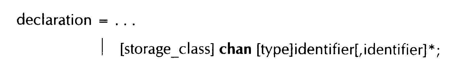
chan struct comm a, b;

extern chanin int from_env;
extern chanout int to_env;
- primitives send (chan,val) and receive (chan). The former sends the
value val down the channel chan. The latter receives a value from
channel chan and may be used to build expressions. Each channel
communicates data in a point-to-point fashion and each of the two
communicating processes must wait for the communication to be
completed before continuing. In addition, there is a function ready
(chan) which is true when there is data waiting to be sent on channel
chan.


- a set of integer types of given bit widths, to allow efficient circuits to
be built to whatever numeric accuracy is required. For this we
extend the set of type modifiers to include #e, where e is a constant
expression, denoting a width equal to the value of e:

chan unsigned#7 c;
- bit selection and bit concatenation operators for constructing efficient
circuits for bit manipulation. The @ symbol is used for
concatenation. The 'grab' operator (written <-) takes an expression,
e, and a list of constant bit-positions, b1...bn. When it is evaluated, it
returns an n bit result, eb1...ebn, where ei is the ith bit of e.

While (x < 1O)
x : = x + (y*y)
... could be rewritten as ...
declare tmp
tmp: = y*y
While (x < 10)
x : = x + tmp
Sequence:
Declare tmp1
tmp1 :=f(x)
send(ch,tmp1)
Declare tmp2
tmp2 := g(y)
send (ch, tmp2)
... could be rewritten as
Sequence:
Declare tmp
tmp := f(x)
send(ch,tmp)
tmp:= g(y)
send(ch,tmp)
- Assignments can be more complex, and may involve channel communication and parameterised function calls. This requires a more complex protocol between parts of expressions so that, for example, a multiplier knows when its arguments are ready.
- Since the compiler produces HDL rather than a netlist, it may leave some choices, in particular the method for implementing state machines and registers, down to the synthesis tools lower in the design chain.
Define IDI("a")
Define 1 D2("b")
a:= 1
b:=a+b

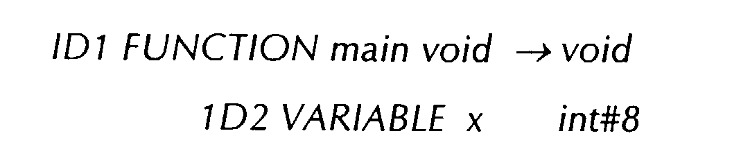
Define ID1("main")
Declare ID2("x")
FOR (x=O(#8); x < 1O(#8); x++)
x<<=1;
Define ID1("main")
Declare ID2 ("x")
x := 0(#8)
While (x < 10(#8))
x := x < < 1
x := x + 1(#8)
Define ID1 ("main")
Declare ID2 ("x")
x := 0(#8)
While (x < 10(#8))
x := (x < < 1) + 1(#8)


Claims (15)
- A method of designing an integrated circuit comprising defining the functions of the integrated circuit in a programming language (1) supporting parallelism and synchronised communication, and applying a compiler (3, 8) which is arranged to retime synchronised communications without changing the order of external communications of the integrated circuit so as to produce output code (2) representing circuitry of the integrated circuit.
- A method as claimed in Claim 1, characterised in that the synchronised communication comprises handshaking.
- A method as claimed in Claim 1 or 2, characterised in that the compiler (3, 8) is arranged to form an abstract syntax tree (7) and a symbol table (5).
- A method as claimed in Claim 3, characterised in that the compiler (3, 8) includes a software optimiser (9) for simplifying the abstract syntax tree (7).
- A method as claimed in Claim 4, characterised in that the software optimiser (9) is arranged to convert compound data structures to component parts such that there is one variable for each component part.
- A method as claimed in Claim 4 or 5, characterised in that the software optimiser (9) is arranged to remove unused variables.
- A method as claimed in any one of Claims 4 to 6, characterised in that the software optimiser is arranged to move common operators outside loops.
- A method as claimed in any one of the preceding claims, characterised in that the compiler (3, 8) includes a hardware optimiser (10) for optimising the hardware implementation represented by the output code.
- A method as claimed in Claim 8, characterised in that the hardware optimiser (10) is arranged to perform scheduling and allocation.
- A method as claimed in any one of Claims 4 to 9, characterised in that the compiler (3, 8) is arranged to terminate optimisation when at least one predetermined performance parameter has been achieved.
- A method as claimed in Claim 10, characterised in that the at least one predetermined performance parameter comprises a maximum integrated circuit area.
- A method as claimed in Claim 10 or 11, in which the at least one predetermined parameter comprises a minimum integrated circuit processing speed.
- A method as claimed in any one of Claims 10 to 12, characterised in that the at least one predetermined parameter comprises a maximum power consumption.
- A method as claimed in any one of the preceding claims, characterised by generating register transfer level code (12) representing circuitry for performing constructs defined by the output code.
- An integrated circuit designed by a method as claimed in any one of the preceding Claims.
Applications Claiming Priority (2)
| Application Number | Priority Date | Filing Date | Title |
|---|---|---|---|
| GB9619096A GB2317245A (en) | 1996-09-12 | 1996-09-12 | Re-timing compiler integrated circuit design |
| GB9619096 | 1996-09-12 |
Publications (2)
| Publication Number | Publication Date |
|---|---|
| EP0829812A2 true EP0829812A2 (en) | 1998-03-18 |
| EP0829812A3 EP0829812A3 (en) | 1999-08-25 |
Family
ID=10799852
Family Applications (1)
| Application Number | Title | Priority Date | Filing Date |
|---|---|---|---|
| EP97307084A Withdrawn EP0829812A3 (en) | 1996-09-12 | 1997-09-12 | Method of designing an integrated circuit and integrated circuit designed by such method |
Country Status (4)
| Country | Link |
|---|---|
| US (1) | US6021266A (en) |
| EP (1) | EP0829812A3 (en) |
| JP (3) | JPH10116302A (en) |
| GB (1) | GB2317245A (en) |
Cited By (21)
| Publication number | Priority date | Publication date | Assignee | Title |
|---|---|---|---|---|
| US6152612A (en) * | 1997-06-09 | 2000-11-28 | Synopsys, Inc. | System and method for system level and circuit level modeling and design simulation using C++ |
| WO2001013285A2 (en) * | 1999-08-19 | 2001-02-22 | Massachusetts Institute Of Technology | Synchronous circuit synthesis using an asynchronous specification |
| WO2001059593A2 (en) * | 2000-02-10 | 2001-08-16 | Xilinx, Inc. | A means and method for compiling high level software languages into algorithmically equivalent hardware representations |
| WO2002013004A2 (en) * | 2000-08-07 | 2002-02-14 | Altera Corporation | Software-to-hardware compiler |
| US6360355B1 (en) | 1998-02-26 | 2002-03-19 | Sharp Kabushiki Kaisha | Hardware synthesis method, hardware synthesis device, and recording medium containing a hardware synthesis program recorded thereon |
| EP1202194A2 (en) * | 2000-10-31 | 2002-05-02 | Sharp Kabushiki Kaisha | High-level synthesis method, high-level synthesis apparatus, method for producing logic circuit using the high-level synthesis method for logic circuit design, and recording medium |
| EP1267287A2 (en) * | 2001-06-11 | 2002-12-18 | Sharp Kabushiki Kaisha | High-level synthesis apparatus and method, method for producing logic circuit using the high-level synthesis method, and recording medium |
| EP1284454A2 (en) * | 2001-08-17 | 2003-02-19 | Sun Microsystems, Inc. | Method and apparatus for simulation system compiler |
| US6658564B1 (en) | 1998-11-20 | 2003-12-02 | Altera Corporation | Reconfigurable programmable logic device computer system |
| WO2004003794A1 (en) * | 2002-06-26 | 2004-01-08 | E-Trees.Japan Inc. | Method and device for quickly processing communication protocol by replacing software with hardware |
| EP1395903A1 (en) * | 2001-06-15 | 2004-03-10 | Verisity Ltd. | Synthesis of verification languages |
| WO2004074962A2 (en) * | 2003-02-21 | 2004-09-02 | Picochip Designs Limited | Allocation of processes to processors in a processor array |
| EP1742159A2 (en) * | 2000-08-07 | 2007-01-10 | Altera Corporation | Software-to-Hardware compiler |
| US7343594B1 (en) | 2000-08-07 | 2008-03-11 | Altera Corporation | Software-to-hardware compiler with symbol set inference analysis |
| US7370312B1 (en) | 2005-01-31 | 2008-05-06 | Bluespec, Inc. | System and method for controlling simulation of hardware in a hardware development process |
| US7647567B1 (en) | 2005-01-31 | 2010-01-12 | Bluespec, Inc. | System and method for scheduling TRS rules |
| US7665059B2 (en) | 2006-06-07 | 2010-02-16 | Bluespec, Inc. | System and method for designing multiple clock domain circuits |
| US7716608B2 (en) | 2005-06-01 | 2010-05-11 | Massachusetts Institute Of Technology | Circuit synthesis with sequential rules |
| US8350594B2 (en) | 2008-11-08 | 2013-01-08 | Massachusetts Institute Of Technology | Hardware synthesis from multicycle rules |
| US8959469B2 (en) | 2012-02-09 | 2015-02-17 | Altera Corporation | Configuring a programmable device using high-level language |
| EP3751412A1 (en) * | 2019-06-11 | 2020-12-16 | ENGEL AUSTRIA GmbH | A computer-implemented method to generate an opc ua information model |
Families Citing this family (38)
| Publication number | Priority date | Publication date | Assignee | Title |
|---|---|---|---|---|
| US5966534A (en) * | 1997-06-27 | 1999-10-12 | Cooke; Laurence H. | Method for compiling high level programming languages into an integrated processor with reconfigurable logic |
| GB2350448A (en) * | 1999-05-27 | 2000-11-29 | Sharp Kk | Multichannel synchronised communication |
| JP3716967B2 (en) * | 1999-07-29 | 2005-11-16 | シャープ株式会社 | High level synthesis apparatus, high level synthesis method, and recording medium used therefor |
| US6519742B1 (en) * | 2000-03-06 | 2003-02-11 | Synplicity, Inc. | Local naming for HDL compilation |
| US6519757B1 (en) * | 2000-04-11 | 2003-02-11 | International Business Machines Corporation | Hardware design language generation for input/output logic level |
| WO2001090887A1 (en) * | 2000-05-25 | 2001-11-29 | Fujitsu Limited | Method fir processing program for high-speed processing by using dynamically reconfigurable hardware and program for executing the processing method |
| US7079281B1 (en) | 2000-08-01 | 2006-07-18 | Eastman Kodak Company | Edge enhancement processor and method with adjustable threshold setting |
| JP2002049652A (en) * | 2000-08-03 | 2002-02-15 | Hiroshi Yasuda | Digital circuit design method, its compiler and simulator |
| US6530069B2 (en) * | 2000-11-29 | 2003-03-04 | Unisys Corporation | Printed circuit board design, testing, and manufacturing process |
| US20030023653A1 (en) * | 2001-01-29 | 2003-01-30 | Andrew Dunlop | System, method and article of manufacture for a single-cycle floating point library |
| JP3895934B2 (en) * | 2001-01-31 | 2007-03-22 | 株式会社東芝 | Specification operation device |
| US6792580B2 (en) * | 2001-01-31 | 2004-09-14 | Kabushiki Kaisha Toshiba | Method and computer program product for software/hardware language model conversion |
| US20030196194A1 (en) * | 2001-10-11 | 2003-10-16 | Johns Clifford R. | Hardware design protocol and system |
| US20040066462A1 (en) * | 2002-10-07 | 2004-04-08 | Mark Medow | Peripheral component interconnect (PCI) card for controlling a motorized zoom lens of a camera |
| WO2004038620A1 (en) * | 2002-10-28 | 2004-05-06 | Renesas Technology Corp. | System development method and data processing system |
| AU2003301126A1 (en) * | 2002-12-17 | 2004-07-14 | Cadence Design Systems, Inc. | Method and system for implementing circuit simulators |
| US7454744B2 (en) * | 2003-07-03 | 2008-11-18 | International Business Machines Corporation | Private source code commenting |
| WO2005086746A2 (en) * | 2004-03-04 | 2005-09-22 | Trustees Of Boston University | Programmable-logic acceleraton of data processing applications |
| JP2005284577A (en) * | 2004-03-29 | 2005-10-13 | Matsushita Electric Ind Co Ltd | Compiler |
| US7506278B1 (en) * | 2005-03-08 | 2009-03-17 | Xilinx, Inc. | Method and apparatus for improving multiplexer implementation on integrated circuits |
| JP2007041796A (en) * | 2005-08-02 | 2007-02-15 | Mitsubishi Electric Corp | Code generation apparatus |
| JP2007287044A (en) * | 2006-04-19 | 2007-11-01 | Toshiba Corp | Design support apparatus |
| EP2033316A4 (en) * | 2006-06-21 | 2010-08-11 | Element Cxi Llc | Fault tolerant integrated circuit architecture |
| FR2902913A1 (en) * | 2006-06-21 | 2007-12-28 | France Telecom | Semantic and spatial similarity note calculating and encoding method for tourism field, involves calculating and encoding semantic and spatial note by relatively comparing with respective common semantic characteristics |
| JP4787711B2 (en) * | 2006-10-02 | 2011-10-05 | 日本電気株式会社 | Data processing apparatus and method, computer program, information storage medium, and data processing system |
| US8418135B2 (en) * | 2007-05-31 | 2013-04-09 | Red Hat, Inc. | Method and apparatus to abstract away rule languages |
| JP5125457B2 (en) * | 2007-12-03 | 2013-01-23 | ヤマハ株式会社 | Control device, acoustic signal processing system, acoustic signal processing device, and control program |
| US8156457B2 (en) * | 2009-09-24 | 2012-04-10 | Synopsys, Inc. | Concurrent simulation of hardware designs with behavioral characteristics |
| JP5751669B2 (en) | 2011-07-08 | 2015-07-22 | ルネサスエレクトロニクス株式会社 | Language conversion processing method and language conversion processing program |
| US9449131B2 (en) * | 2014-06-02 | 2016-09-20 | Xilinx, Inc. | Extracting system architecture in high level synthesis |
| WO2016168636A1 (en) * | 2015-04-17 | 2016-10-20 | Ball Corporation | Method and apparatus for controlling the speed of a continuous sheet of material |
| US10421111B2 (en) | 2015-04-17 | 2019-09-24 | Ball Corporation | Method and apparatus for controlling an operation performed on a continuous sheet of material |
| JP6407181B2 (en) * | 2016-03-04 | 2018-10-17 | 三菱電機株式会社 | Design support apparatus, design support method, and design support program |
| US10628284B2 (en) * | 2017-04-24 | 2020-04-21 | Tektronix, Inc. | System and method for bitstream decoding with compiler-generated syntax trees |
| JP2018200634A (en) * | 2017-05-29 | 2018-12-20 | 富士通株式会社 | SystemC model generating method and SystemC model generating program |
| US10671779B1 (en) * | 2018-07-09 | 2020-06-02 | Xilinx, Inc. | Function calls in high level synthesis |
| US11520369B2 (en) * | 2020-02-04 | 2022-12-06 | Qualcomm Incorporated | Clock instantaneous temperature-rate-of-change measurement |
| CN113536717B (en) * | 2021-07-14 | 2022-05-24 | 北京华大九天科技股份有限公司 | Circuit simulation method based on incremental compilation |
Citations (1)
| Publication number | Priority date | Publication date | Assignee | Title |
|---|---|---|---|---|
| EP0329233A2 (en) * | 1988-02-16 | 1989-08-23 | Koninklijke Philips Electronics N.V. | Silicon-compiler method and arrangement |
Family Cites Families (9)
| Publication number | Priority date | Publication date | Assignee | Title |
|---|---|---|---|---|
| US5598344A (en) * | 1990-04-06 | 1997-01-28 | Lsi Logic Corporation | Method and system for creating, validating, and scaling structural description of electronic device |
| US5557531A (en) * | 1990-04-06 | 1996-09-17 | Lsi Logic Corporation | Method and system for creating and validating low level structural description of electronic design from higher level, behavior-oriented description, including estimating power dissipation of physical implementation |
| US5870308A (en) * | 1990-04-06 | 1999-02-09 | Lsi Logic Corporation | Method and system for creating and validating low-level description of electronic design |
| US5555201A (en) * | 1990-04-06 | 1996-09-10 | Lsi Logic Corporation | Method and system for creating and validating low level description of electronic design from higher level, behavior-oriented description, including interactive system for hierarchical display of control and dataflow information |
| US5603043A (en) * | 1992-11-05 | 1997-02-11 | Giga Operations Corporation | System for compiling algorithmic language source code for implementation in programmable hardware |
| US5483640A (en) * | 1993-02-26 | 1996-01-09 | 3Com Corporation | System for managing data flow among devices by storing data and structures needed by the devices and transferring configuration information from processor to the devices |
| US5493508A (en) * | 1994-06-01 | 1996-02-20 | Lsi Logic Corporation | Specification and design of complex digital systems |
| US5537580A (en) * | 1994-12-21 | 1996-07-16 | Vlsi Technology, Inc. | Integrated circuit fabrication using state machine extraction from behavioral hardware description language |
| US5793824A (en) * | 1996-04-30 | 1998-08-11 | Adtran, Inc. | Digital phase locked loop having adaptive bandwidth for pulse stuffing synchronized digital communication system |
-
1996
- 1996-09-12 GB GB9619096A patent/GB2317245A/en not_active Withdrawn
-
1997
- 1997-09-10 US US08/926,641 patent/US6021266A/en not_active Expired - Lifetime
- 1997-09-12 EP EP97307084A patent/EP0829812A3/en not_active Withdrawn
- 1997-09-12 JP JP9249152A patent/JPH10116302A/en active Pending
-
2002
- 2002-11-07 JP JP2002324539A patent/JP2003223473A/en active Pending
- 2002-11-07 JP JP2002324538A patent/JP3835754B2/en not_active Expired - Fee Related
Patent Citations (1)
| Publication number | Priority date | Publication date | Assignee | Title |
|---|---|---|---|---|
| EP0329233A2 (en) * | 1988-02-16 | 1989-08-23 | Koninklijke Philips Electronics N.V. | Silicon-compiler method and arrangement |
Non-Patent Citations (7)
| Title |
|---|
| BERKEL VAN C H ET AL: "COMPILATION OF COMMUNICATING PROCESSES INTO DELAY-INSENSITIVE CIRCUITS" PROCEEDINGS OF THE INTERNATIONAL CONFERENCE ON COMPUTER DESIGN: VL IN COMPUTERS AND PROCESSORS. (ICCD), NEW YORK, OCT. 3 - 5, 1988,3 October 1988, pages 157-162, XP000744203 INSTITUTE OF ELECTRICAL AND ELECTRONICS ENGINEERS * |
| BRUNVAND E: "DESIGNING SELF-TIMED SYSTEMS USING CONCURRENT PROGRAMS" JOURNAL OF VLSI SIGNAL PROCESSING, vol. 7, no. 1/02, 1 February 1994, pages 47-59, XP000434685 * |
| CHU C.-M.; POTKONJAK M.; THALER M.; RABAEY J.: 'HYPER: an interactive synthesis environment for high performance real time applications (XP10017158)' PROCEEDINGS. 1989 IEEE INTERNATIONAL CONFERENCE ON COMPUTER DESIGN: VLSI IN COMPUTERS AND PROCESSORS 02 October 1989 - 04 October 1989, CAMBRIDGE, MA, USA, pages 432 - 435 * |
| DENK T C ET AL: "A UNIFIED FRAMEWORK FOR CHARACTERIZING RETIMING AND SCHEDULING SOLUTIONS" 1996 IEEE INTERNATIONAL SYMPOSIUM ON CIRCUITS AND SYSTEMS (ISCAS) CIRCUITS AND SYSTEMS CONNECTING THE WORLD, ATLANTA, MAY 12 - 15, 1996, vol. 4, 12 May 1996, pages 568-571, XP000704663 INSTITUTE OF ELECTRICAL AND ELECTRONICS ENGINEERS * |
| LEWIS J.: 'EDA environments in 1995: specification, not implementation (XP010022546)' COMPCON SPRING 91 vol. 25, no. 1, March 1991, SAN FRANCISCO, pages 424 - 427 * |
| NEWMAN M ET AL: "Constraint-based hierarchical placement of parallel programs" FIELD-PROGRAMMABLE LOGIC ARCHITECTURES, SYNTHESIS AND APPLICATIONS. 4TH INTERNATIONAL WORKSHOP ON FIELD-PROGRAMMABLE LOGIC AND APPLICATIONS, FPL '94. PROCEEDINGS, FIELD-PROGRAMMABLE LOGIC. ARCHITECTURES, SYNTHESIS AND APPLICATIONS. 4TH INTERNATIONAL , pages 220-229, XP002107161 ISBN 3-540-58419-6, 1994, Berlin, Germany, Springer-Verlag, Germany * |
| PAGE IAN: 'Constructing hardware-software systems from a single description' JOURNAL OF VLSI SIGNAL PROCESSING SYSTEMS FOR SIGNAL, IMAGE, AND VIDEO TECHNOLOGY vol. 12, no. 1, January 1996, DORDRECHT, NL, pages 87 - 107, XP000552006 * |
Cited By (45)
| Publication number | Priority date | Publication date | Assignee | Title |
|---|---|---|---|---|
| US6152612A (en) * | 1997-06-09 | 2000-11-28 | Synopsys, Inc. | System and method for system level and circuit level modeling and design simulation using C++ |
| US6360355B1 (en) | 1998-02-26 | 2002-03-19 | Sharp Kabushiki Kaisha | Hardware synthesis method, hardware synthesis device, and recording medium containing a hardware synthesis program recorded thereon |
| USRE42444E1 (en) | 1998-11-20 | 2011-06-07 | Altera Corporation | Method for managing resources in a reconfigurable computer having programmable logic resources where automatically swapping configuration data between a secondary storage device and the programmable logic resources |
| US7171548B2 (en) | 1998-11-20 | 2007-01-30 | Altera Corporation | Method for managing resources in a reconfigurable computer having programmable logic resources where automatically swapping configuration data between a secondary storage device and the programmable logic resources |
| US6658564B1 (en) | 1998-11-20 | 2003-12-02 | Altera Corporation | Reconfigurable programmable logic device computer system |
| WO2001013285A2 (en) * | 1999-08-19 | 2001-02-22 | Massachusetts Institute Of Technology | Synchronous circuit synthesis using an asynchronous specification |
| WO2001013285A3 (en) * | 1999-08-19 | 2002-01-31 | Massachusetts Inst Technology | Synchronous circuit synthesis using an asynchronous specification |
| US8108810B2 (en) | 1999-08-19 | 2012-01-31 | Massachusetts Institute Of Technology | Synchronous circuit synthesis using an asynchronous specification |
| US6901055B1 (en) | 1999-08-19 | 2005-05-31 | Massachusetts Institute Of Technology | Synchronous circuit synthesis using an asynchronous specification |
| US6625797B1 (en) | 2000-02-10 | 2003-09-23 | Xilinx, Inc. | Means and method for compiling high level software languages into algorithmically equivalent hardware representations |
| WO2001059593A2 (en) * | 2000-02-10 | 2001-08-16 | Xilinx, Inc. | A means and method for compiling high level software languages into algorithmically equivalent hardware representations |
| WO2001059593A3 (en) * | 2000-02-10 | 2002-06-13 | Xilinx Inc | A means and method for compiling high level software languages into algorithmically equivalent hardware representations |
| WO2002013004A3 (en) * | 2000-08-07 | 2003-08-21 | Altera Corp | Software-to-hardware compiler |
| EP1742159A2 (en) * | 2000-08-07 | 2007-01-10 | Altera Corporation | Software-to-Hardware compiler |
| WO2002013004A2 (en) * | 2000-08-07 | 2002-02-14 | Altera Corporation | Software-to-hardware compiler |
| US8332831B1 (en) | 2000-08-07 | 2012-12-11 | Altera Corporation | Software-to-hardware compiler with symbol set inference analysis |
| US8473926B2 (en) | 2000-08-07 | 2013-06-25 | Altera Corporation | Software-to-hardware compiler |
| US7343594B1 (en) | 2000-08-07 | 2008-03-11 | Altera Corporation | Software-to-hardware compiler with symbol set inference analysis |
| US8930922B2 (en) | 2000-08-07 | 2015-01-06 | Altera Corporation | Software-to-hardware compiler with symbol set inference analysis |
| US7257780B2 (en) | 2000-08-07 | 2007-08-14 | Altera Corporation | Software-to-hardware compiler |
| EP1742159A3 (en) * | 2000-08-07 | 2007-06-20 | Altera Corporation | Software-to-Hardware compiler |
| US7219342B2 (en) | 2000-08-07 | 2007-05-15 | Altera Corporation | Software-to-hardware compiler |
| EP1202194A2 (en) * | 2000-10-31 | 2002-05-02 | Sharp Kabushiki Kaisha | High-level synthesis method, high-level synthesis apparatus, method for producing logic circuit using the high-level synthesis method for logic circuit design, and recording medium |
| EP1202194A3 (en) * | 2000-10-31 | 2003-05-02 | Sharp Kabushiki Kaisha | High-level synthesis method, high-level synthesis apparatus, method for producing logic circuit using the high-level synthesis method for logic circuit design, and recording medium |
| US6687894B2 (en) | 2000-10-31 | 2004-02-03 | Sharp Kabushiki Kaisha | High-level synthesis method, high-level synthesis apparatus, method for producing logic circuit using the high-level synthesis method for logic circuit design, and recording medium |
| EP1267287A2 (en) * | 2001-06-11 | 2002-12-18 | Sharp Kabushiki Kaisha | High-level synthesis apparatus and method, method for producing logic circuit using the high-level synthesis method, and recording medium |
| US6832363B2 (en) | 2001-06-11 | 2004-12-14 | Sharp Kabushiki Kaisha | High-level synthesis apparatus, high-level synthesis method, method for producing logic circuit using the high-level synthesis method, and recording medium |
| EP1267287A3 (en) * | 2001-06-11 | 2003-12-17 | Sharp Kabushiki Kaisha | High-level synthesis apparatus and method, method for producing logic circuit using the high-level synthesis method, and recording medium |
| EP1395903A4 (en) * | 2001-06-15 | 2008-02-27 | Verisity Ltd | Synthesis of verification languages |
| EP1395903A1 (en) * | 2001-06-15 | 2004-03-10 | Verisity Ltd. | Synthesis of verification languages |
| EP1284454A2 (en) * | 2001-08-17 | 2003-02-19 | Sun Microsystems, Inc. | Method and apparatus for simulation system compiler |
| EP1284454A3 (en) * | 2001-08-17 | 2004-09-08 | Sun Microsystems, Inc. | Method and apparatus for simulation system compiler |
| WO2004003794A1 (en) * | 2002-06-26 | 2004-01-08 | E-Trees.Japan Inc. | Method and device for quickly processing communication protocol by replacing software with hardware |
| WO2004074962A3 (en) * | 2003-02-21 | 2005-02-24 | Picochip Designs Ltd | Allocation of processes to processors in a processor array |
| WO2004074962A2 (en) * | 2003-02-21 | 2004-09-02 | Picochip Designs Limited | Allocation of processes to processors in a processor array |
| US7647567B1 (en) | 2005-01-31 | 2010-01-12 | Bluespec, Inc. | System and method for scheduling TRS rules |
| US7370312B1 (en) | 2005-01-31 | 2008-05-06 | Bluespec, Inc. | System and method for controlling simulation of hardware in a hardware development process |
| US7716608B2 (en) | 2005-06-01 | 2010-05-11 | Massachusetts Institute Of Technology | Circuit synthesis with sequential rules |
| US7665059B2 (en) | 2006-06-07 | 2010-02-16 | Bluespec, Inc. | System and method for designing multiple clock domain circuits |
| US8572534B2 (en) | 2006-06-07 | 2013-10-29 | Bluespec, Inc. | System and method for designing multiple clock domain circuits |
| US8350594B2 (en) | 2008-11-08 | 2013-01-08 | Massachusetts Institute Of Technology | Hardware synthesis from multicycle rules |
| US8959469B2 (en) | 2012-02-09 | 2015-02-17 | Altera Corporation | Configuring a programmable device using high-level language |
| US9449132B2 (en) | 2012-02-09 | 2016-09-20 | Altera Corporation | Configuring a programmable device using high-level language |
| US10366189B2 (en) | 2012-02-09 | 2019-07-30 | Altera Corporation | Configuring a programmable device using high-level language |
| EP3751412A1 (en) * | 2019-06-11 | 2020-12-16 | ENGEL AUSTRIA GmbH | A computer-implemented method to generate an opc ua information model |
Also Published As
| Publication number | Publication date |
|---|---|
| JP2003216668A (en) | 2003-07-31 |
| US6021266A (en) | 2000-02-01 |
| EP0829812A3 (en) | 1999-08-25 |
| GB9619096D0 (en) | 1996-10-23 |
| JP2003223473A (en) | 2003-08-08 |
| GB2317245A (en) | 1998-03-18 |
| JP3835754B2 (en) | 2006-10-18 |
| JPH10116302A (en) | 1998-05-06 |
Similar Documents
| Publication | Publication Date | Title |
|---|---|---|
| US6021266A (en) | Method of designing an integrated circuit using scheduling and allocation with parallelism and handshaking communication, and an integrated circuit designed by such method | |
| Coussy et al. | GAUT: A High-Level Synthesis Tool for DSP Applications: From C Algorithm to RTL Architecture | |
| Bolsens et al. | Hardware/software co-design of digital telecommunication systems | |
| Gajski et al. | Introduction to high-level synthesis | |
| US8473926B2 (en) | Software-to-hardware compiler | |
| JP4014080B2 (en) | Digital circuit design apparatus and design method, program, and storage medium | |
| Lin et al. | Synthesis of concurrent system interface modules with automatic protocol conversion generation | |
| WO2002061631A2 (en) | System, method and article of manufacture for using a library map to create and maintain ip cores effectively | |
| De Man et al. | Co-design of DSP systems | |
| Van Eijndhoven et al. | A data flow graph exchange standard | |
| EP1065611A2 (en) | A design environment for hardware/software co-design | |
| Sharp | Higher-level hardware synthesis | |
| Vahid et al. | Functional partitioning improvements over structural partitioning for packaging constraints and synthesis: tool performance | |
| EP0867820A2 (en) | A design environment and a method for generating an implementable description of a digital system | |
| Lavagno et al. | Embedded system co-design: Synthesis and verification | |
| Zhao et al. | Using vivado-HLS for structural design: A NoC case study | |
| Ortega et al. | Models and methods for hw/sw intellectual property interfacing | |
| Hoover et al. | Synthesizing synchronous elastic flow networks | |
| US6449763B1 (en) | High-level synthesis apparatus, high level synthesis method, and recording medium carrying a program for implementing the same | |
| Koch et al. | Modeling and synthesis of hardware-software morphing | |
| Bergeron et al. | High level synthesis for data-driven applications | |
| Cesário et al. | Overlap and frontiers between behavioral and RTL synthesis | |
| Glunz et al. | System-level synthesis | |
| Gajski | System-level design methodology | |
| Van Leeuwen | Implementation and automatic generation of asynchronous scheduled dataflow graph |
Legal Events
| Date | Code | Title | Description |
|---|---|---|---|
| PUAI | Public reference made under article 153(3) epc to a published international application that has entered the european phase |
Free format text: ORIGINAL CODE: 0009012 |
|
| AK | Designated contracting states |
Kind code of ref document: A2 Designated state(s): DE FR GB |
|
| PUAL | Search report despatched |
Free format text: ORIGINAL CODE: 0009013 |
|
| AK | Designated contracting states |
Kind code of ref document: A3 Designated state(s): AT BE CH DE DK ES FI FR GB GR IE IT LI LU MC NL PT SE |
|
| 17P | Request for examination filed |
Effective date: 20000204 |
|
| AKX | Designation fees paid |
Free format text: DE FR GB |
|
| 17Q | First examination report despatched |
Effective date: 20030319 |
|
| STAA | Information on the status of an ep patent application or granted ep patent |
Free format text: STATUS: THE APPLICATION HAS BEEN WITHDRAWN |
|
| 18W | Application withdrawn |
Effective date: 20051010 |