EP0826958B1 - Method and apparatus for obtaining information on the optical absorption of a scattering medium - Google Patents
Method and apparatus for obtaining information on the optical absorption of a scattering medium Download PDFInfo
- Publication number
- EP0826958B1 EP0826958B1 EP97306693A EP97306693A EP0826958B1 EP 0826958 B1 EP0826958 B1 EP 0826958B1 EP 97306693 A EP97306693 A EP 97306693A EP 97306693 A EP97306693 A EP 97306693A EP 0826958 B1 EP0826958 B1 EP 0826958B1
- Authority
- EP
- European Patent Office
- Prior art keywords
- angular frequency
- modulation angular
- scattering medium
- modulated light
- signals
- Prior art date
- Legal status (The legal status is an assumption and is not a legal conclusion. Google has not performed a legal analysis and makes no representation as to the accuracy of the status listed.)
- Expired - Lifetime
Links
Images


Classifications
-
- G—PHYSICS
- G01—MEASURING; TESTING
- G01N—INVESTIGATING OR ANALYSING MATERIALS BY DETERMINING THEIR CHEMICAL OR PHYSICAL PROPERTIES
- G01N21/00—Investigating or analysing materials by the use of optical means, i.e. using sub-millimetre waves, infrared, visible or ultraviolet light
- G01N21/17—Systems in which incident light is modified in accordance with the properties of the material investigated
- G01N21/47—Scattering, i.e. diffuse reflection
- G01N21/49—Scattering, i.e. diffuse reflection within a body or fluid
Definitions
- the present invention relates to an absorption information measuring method and apparatus of scattering medium and, more particularly, to a method and apparatus for measuring a temporal change or a spatial distribution of concentration of an absorptive constituent in a scattering medium having non-reentrant surfaces.
- the invention further concerns a method and apparatus for measuring a concentration of an absorptive constituent inside the scattering medium by use of light of plural wavelengths.
- the scattering medium like the living body propagates inside as scattered and absorbed therein, and then part thereof emerges from its surface. Since the outside of the scattering medium is normally air, the light emerging from the surface is dispersed in the free space. The light emerging from the surface as described above is detected in measurements of internal information of scattering medium. At this time the propagating light spreads throughout the entire region of scattering medium and is dispersed from the whole surface to the outside. Therefore, when the output light is detected at a specific position in the surface, the quantity or a time-resolved waveform of detected light greatly varies with change in the shape of medium, for example, depending upon whether it is a sphere or a rectangular parallelepiped.
- boundary conditions differ greatly depending upon the shape of scattering medium, new boundary conditions must be set to solve the photon diffusion equation for every change in the shape of scattering medium, in order to achieve accurate measurement.
- Scattering media for which the boundary conditions can be set accurately to some extent are limited to very simple shapes such as an infinite space, a semi-infinite space, an infinite cylinder, or a slab spreading infinitely and having a finite thickness.
- use of approximate boundary conditions is indispensable to measurements of living tissues having complicated shapes, which is a cause to produce large measuring errors.
- US patent application 5,122,974 relates to methods and apparatus for studying photon migration using signal modulation techniques such as time, frequency and phase modulation.
- the photon migration data may then be converted, using the principles of time-resolved spectroscopy, to determine the concentration of an absorptive constituent in a scattering medium, such as the concentration of hemoglobin in a brain of other tissue.
- US patent 5,424,832 relates to an apparatus and method for qualitative and quantitative optical measurements by using multiple light scattering for exposing a sample to a modulated laser beam.
- the light beam is modulated at a fundamental frequency and at a plurality of integer harmonics thereof.
- Modulated light is returned from the sample and preferentially detected at cross frequencies at frequencies slightly higher than the fundamental frequency and at integer harmonics of the same.
- the received radiance is compared against a reference signal to provide a measure of the phase lag of the radiance and modulation ratio relative to a reference beam. In this way the absorption and scattering coefficients are determined together with a concentration of the active substance in the sample.
- the present invention has been accomplished in view of the problems in the conventional technologies described above and an object of the invention is to newly disclose a method for describing the behavior of light inside the scattering media of different shapes (basic relations) and to provide a measuring method and measuring apparatus of absorption information inside the scattering medium, realizing measurements of change, absolute value, or the like of concentration of a specific absorptive constituent in the scattering media of various shapes by use of the relations, greatly improving the measurement accuracy thereof, and being capable of efficiently measuring a temporal change or a spatial distribution thereof.
- a difference of concentration of an absorptive constituent can be quantified based on a predetermined relation among this difference between absorption coefficients, an absorption coefficient per unit concentration of the absorptive constituent, and the difference of concentration of the absorptive constituent.
- a difference of concentration of an absorptive constituent can be calculated based on a predetermined relation among this difference between absorption coefficients, an absorption coefficient per unit concentration of the absorptive constituent, and the difference of concentration of the absorptive constituent.
- the contours of the scattering medium are assumed to be those having non-reentrant surfaces; that is, the medium is of an arbitrary shape that keeps diffuse light emerging from the medium from reentering the medium.
- the incident light is assumed to be one having an arbitrary time-resolved waveform.
- the incident light of the arbitrary time-resolved waveform can be expressed, as apparent from the Fourier transform principle, by superposition of light components modulated at various frequencies, and thus the following discussion will be given in the frequency aspect, considering the incident light of an arbitrary modulation frequency.
- Fig. 1 shows an example of track of a detected photon which has propagated inside a scattering medium or a scattering absorptive body.
- the light is strongly scattered by scattering constituents, so that the optical path of the photon is bent in a zig-zag pattern.
- the Lambert-Beer's law holds for the zig-zag flight pathlength and the intensity of propagating light is exponentially attenuated against the zig-zag flight pathlength (cumulative length).
- J is a term representing the impulse response or output light
- exp(-c ⁇ a t) a term representing attenuation due to the absorption coefficient ⁇ a .
- the all functions are time-causal functions which become zero when t ⁇ 0.
- ⁇ s is the scattering coefficient.
- R(c ⁇ a , ⁇ ) and X(c ⁇ a , ⁇ ) are the real part (sine component) and the imaginary part (cosine component), respectively, and A(c ⁇ a , ⁇ ) and ⁇ (c ⁇ a , ⁇ ) are the amplitude and phase, respectively.
- a phase delay is the phase with the opposite sign.
- the scattering characteristics may be considered not to change with change in the concentration of absorptive constituent. This is just as if ink is mixed in milk.
- p i is a suitable value satisfying the condition of 0 ⁇ p i ⁇ 1.
- This relation can be expressed by the following equation. ⁇ B i c ⁇ a , ⁇ ⁇ ⁇ ⁇
- ⁇ 1 B i ⁇ c ⁇ a , ⁇ 1 + ⁇ / 2 - B i ⁇ c ⁇ a , ⁇ 1 - ⁇ / 2 ⁇
- ⁇ V concentration change ⁇ V of absorptive constituent
- ⁇ V concentration change ⁇ a ⁇ 2 - ⁇ a ⁇ 1
- ⁇ is an absorption coefficient (or an extinction coefficient) per unit concentration of absorptive constituent, which can be measured by a spectrometer. Changes in concentrations of two or more types of absorptive constituents can also be measured using light having two or more wavelengths by the above method.
- These measurements according to the present invention can be applied to scattering media of various shapes having non-reentrant contours, and specific application examples include fluoroscopes, optical CT, clinical monitors utilized in surgery or cure, and so on, as well as the photo-mammography. These examples utilize such methods as light reception at multiple points, scanning of light incidence position and light receiving position, and time-sharing measurement as occasion may demand.
- the following describes the measurement with modulated light (of modulation angular frequency ⁇ ) from light having two wavelengths ⁇ 1 and ⁇ 2 , i.e., the dual-wavelength spectrophotometry.
- the concentration V of a specific absorptive constituent is calculated from the below equation, using the absorption coefficients (or extinction coefficients) per unit concentration of the specific absorptive constituent for the light of wavelengths ⁇ 1 and ⁇ 2 , ⁇ 1 and ⁇ 2 .
- V ⁇ ⁇ 2 - ⁇ 1 ⁇ a ⁇ 2 - ⁇ a ⁇ 1
- values of ⁇ 1 and ⁇ 2 can be preliminarily measured by the electrometer. Accordingly, the absolute concentration V of absorptive constituent can be measured in the exactly same manner as the aforementioned measurement of concentration change of absorptive constituent.
- Equation corresponding to foregoing Eq. (6.3) becomes as follows by use of the scattering coefficients ⁇ s1 and ⁇ s2 of the measured medium for the light of the wavelengths ⁇ 1 and ⁇ 2 .
- ⁇ x is a suitable value satisfying the condition of ⁇ a1 ⁇ ⁇ x ⁇ ⁇ a2 or ⁇ a1 ⁇ ⁇ x ⁇ ⁇ a2 .
- k ⁇ ' s1 / ⁇ ' s2 can be derived by solving the photon diffusion equation for a medium of a simple shape.
- ⁇ ' s1 and ⁇ ' s2 are transport scattering coefficients at the wavelengths ⁇ 1 , and ⁇ 2' respectively. Accordingly, the difference between the absorption coefficients, ⁇ a2 - ⁇ a1 , of the medium containing the specific absorptive constituent for the light of the two wavelengths can be calculated from Eq. (15). Then the concentration V of the specific absorptive constituent can be further calculated from Eq. (13).
- the measurement of spatial distribution of concentration of absorptive constituent is achieved by performing the above-stated measurement at multiple points.
- This measurement according to the present invention enables measurements with the scattering media of various shapes having non-reentrant contours.
- Specific application examples include the photo-mammography, fluoroscopes, optical CT, and so on. These examples employ the methods such as the light reception at multiple points, scanning of light incidence position and light receiving position, and the time-sharing measurement as occasion may demand.
- the features of these measurements are the capability of measuring the spatial distribution of concentration of specific absorptive constituent, the spatial distribution of difference between absorptive constituents of the measured medium for the light of two wavelengths, the spatial distribution of temporal change of concentration of specific absorptive constituent, and so on, as described above. These pieces of information are utilized in the clinical monitor, diagnosis or analysis, and surgery or cure.
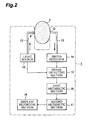
- Fig. 2 shows the first embodiment of the apparatus of the present invention for carrying out the method of the present invention and illustrates the configuration of apparatus 1 for measuring the temporal change of concentration of absorptive constituent inside scattering medium 2.
- a change in the concentration of an absorptive constituent inside the scattering medium is quantified by repetitively carrying out measurements.
- the change in the concentration of the absorptive constituent can be quantified by taking a concentration of the absorptive constituent in the first measurement as a reference value.
- the measuring apparatus 1 is integrally housed in one casing.
- a laser diode or the like is used as light source 10, and the modulated light of wavelength ⁇ and predetermined modulation angular frequency ⁇ is generated thereby.
- the wavelength is selected depending upon the scattering medium and the absorptive constituent to be measured.
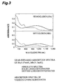
- oxygenated and deoxygenated hemoglobin and oxygenated and deoxygenated myoglobin is often measured and absorption spectra of those absorptive constituents are shown in Fig. 3. Therefore, the light of 600 nm to 1.3 ⁇ m is normally used in the measurements of living body.
- the light source 10 can also be selected from the light-emitting diode, HeNe laser, and so on, as well as the laser diode.
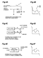
- Sinusoidal modulated light of the predetermined angular frequency is generated by current modulation of the laser diode as shown in Figs. 4A and 4B.
- the sinusoidal modulated light can also be generated by beat of two cw lasers or by use of an optical modulator, as shown in Figs. 4C and 4D and in Figs. 4E and 4F.
- the modulated light emitted from the light source 10 is incident through light guide 12 to the surface of scattering medium 2, which is a measured object.
- the space between the light guide 12 and the scattering medium 2 is very small in the embodiment of Fig. 2. In practice, however, this space may be widened and may be filled with a liquid substance or a jelly substance (which will be called an interface material) having the refractive index and scattering coefficient nearly equal to those of the scattering medium 2. Namely, the modulated light propagates in this interface material to enter the measured object without posing any problem. If reflection on the surface of scattering medium is problematic, influence of the surface reflection or the like can be decreased by properly selecting the interface material.
- Photodetector 14 converts an optical signal of the light received into an electric signal, amplifies it if necessary, and outputs a measurement signal.
- the photodetector 14 may be selected from a phototube, a photodiode, an avalanche photodiode, a PIN photodiode, and so on, in addition to a photomultiplier tube. In selection of the photodiode, it needs to have the spectral sensitivity characteristics for detecting the light of predetermined wavelengths and necessary time response speed.
- a high-gain photodetector For weak light signals, a high-gain photodetector is used. Further, the time correlation photon counting method for counting photons may be applied.
- the other places than the light receiving surface of photodetector are desirably constructed in structure for absorbing or intercepting the light.
- Signal detecting section 15 detects a signal of the predetermined modulation frequency component from the aforementioned measurement signal. Specifically, the monodyne detection, heterodyne detection, or lock-in detection, well known, is used. In this case, the signal detecting section 15 utilizes a signal synchronized with the modulated light emitted from the light source 10 as occasion demands. First arithmetic section 16 calculates the amplitude A and the inclination (derivative) ⁇ / ⁇ of phase ⁇ against the modulation angular frequency from the foregoing signal of the predetermined modulation frequency component. Then the above measurement is carried out repetitively. Now, let us consider the m-th and (m + 1)-th measurements.
- Second arithmetic section 17 substitutes two said amplitudes A m and A m+1 obtained in the m-th and (m + 1)-th measurements, and an inclination of phase ⁇ / ⁇
- the second arithmetic section 17 has a function to store the concentration information of absorptive constituent thus obtained and display/recording means 18 is a section for displaying or recording these information pieces.
- modulated light of one wavelength but modulated light of two or more wavelengths may also be utilized in practice. Further, it is also possible to make the light incident to one position and to detect the propagating light at two or more positions. These may be detected in parallel or in time division.
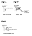
- the means for making the light incident to the scattering medium 2 may be selected from a method with a condenser lens (Fig. 5A), a method using an optical fiber (Fig. 5B), a method utilizing a pinhole (Fig. 5C), a method for making the light incident from inside a body like a gastrocamera (Fig. 5D), and so on.
- a thick beam of light may also be made incident to the scattering medium 2.
- the light source may be regarded as an array of plural spot light sources.
- the means for detecting the light having diffuse-propagated inside the scattering medium 2, other than the method using the light guide 13 shown in Fig. 2, may be selected from a method for directly detecting it (Fig. 6A), a method using an optical fiber (Fig. 6B), a method using a lens (Fig. 6C), and so on.
- the above first arithmetic section 16 was described as to the case for calculating the amplitude A and inclination ⁇ / ⁇ of phase ⁇ against modulation angular frequency from the signal of the predetermined modulation frequency component. However, it may also calculate from the signal of the predetermined modulation frequency component either one combination of (i) the sine component with the inclination (derivative) of cosine component against modulation angular frequency, (ii) the cosine component with the inclination (derivative) of sine component against modulation angular frequency, or (iii) the phase with the inclination (derivative) of natural logarithm of amplitude against modulation angular frequency, as described previously.
- amplitude A, inclination ⁇ / ⁇ of phase ⁇ against modulation angular frequency, and Eq. (7.3)" in above Embodiment 1 should read (i) "sine component, inclination (derivative) of cosine component against modulation angular frequency, and Eq. (7.1),” (ii) “cosine component, inclination (derivative) of sine component against modulation angular frequency, and Eq. (7.2),” or (iii) "phase, inclination (derivative) of natural logarithm of amplitude against modulation angular frequency, and Eq. (7.4).” Accordingly, the first embodiment stated herein can quantify the change of concentration of absorptive constituent according to Eqs. (7.1) to (7.4).
- Measurements are carried out in the same manner as in above Embodiment 1 except for synchronous scanning of the light incidence position P and photodetection position Q of the modulated light relative to the scattering medium 2, and the reference value is a concentration of the absorptive constituent at an arbitrary position, whereby a spatial distribution of concentration difference from the reference value can be measured. Also in this case, similarly as in above Embodiment 1, the spatial distribution of difference of concentration of absorptive constituent from the reference value can be measured using Eqs. (7.1) to (7.4).
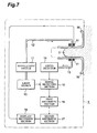
- Fig. 7 shows the second embodiment of the apparatus of the present invention for carrying out the method of the present invention and illustrates the configuration of apparatus 1 (mammography) for measuring the spatial distribution of concentration of absorptive constituent inside the scattering medium 2 like the breast.
- apparatus 1 mammography
- Fig. 7 the components having the same functions as those shown in Fig. 2 associated with the aforementioned first embodiment are denoted by the same symbols.
- the measurement is conducted while synchronously moving the incidence position and photodetection position of the modulated light. Then, for example, using a concentration of the absorptive constituent in the measurement at the first position (the first light incidence position and first photodetection position) as the reference value, the spatial distribution of concentration difference of absorptive constituent can be measured.
- the apparatus 1 shown in Fig. 7 associated with the second embodiment has first mechanical section 30 for lightly nipping the scattering medium 2 in parallel.
- the first mechanical section 30 enables the scattering medium 2 like the breast to be measured in a slightly flattened state.
- This first mechanical section 30 is equipped with second mechanical section 31 for synchronously moving the incidence position and photodetection position of the modulated light. Then this second mechanical section 31 outputs position signals indicating scanning positions and the position signals are supplied to the display/recording section 18 to be utilized for display or recording of the spatial distribution.
- Wavelength selector 11 is disposed in the post-stage of light source 10 for emitting the modulated light, so that modulated light of a desired wavelength can be selected with necessity.
- the other portions are the same as in the apparatus of the first embodiment described above.
- modulated light of one wavelength but modulated light of two or more wavelengths may be used in practice. Further, it is also possible to make the light incident to one light incidence position and to detect the propagating light at two or more photodetection positions simultaneously or in time division.
- Fig. 8 shows the third embodiment of the apparatus of the present invention for carrying out the method of the present invention and illustrates the configuration of the apparatus for measuring the concentration of absorptive constituent inside the scattering medium 2.
- the components having the same functions as those in Fig. 2 associated with the first embodiment and in Fig. 7 associated with the second embodiment are denoted by the same symbols.
- This configuration is arranged to use the modulated light of two wavelengths ⁇ 1 and ⁇ 2 and two photodetection distances r 1 and r 2 . In this case, Eq. (15) described previously holds for each of measurements at the two photodetection distances r 1 and r 2 .
- the difference between the absorption coefficients of the measured scattering medium 2 for the light of two wavelengths, ⁇ a2 - ⁇ a1 can be obtained by eliminating the coefficient b 2 /b 1 in Eq. (15) from simultaneous equations comprised of two equations based on Eq. (15).
- k ⁇ ' s1 / ⁇ ' s2 may be assumed as described previously.
- the difference ⁇ a2 - ⁇ a1 between the absorption coefficients of the medium containing a specific absorptive constituent for the light of the two wavelengths is calculated from Eq. (15) and the concentration of the absorptive constituent in the scattering medium can be quantified based on the relation shown in Eq. (13).
- the modulated light from the light source 10 is subjected to wavelength selection by the wavelength selector 11 and is guided through the light guide 12 to the surface of scattering medium 2 being the measured object.
- the apparatus may employ a method for making the modulated light beams of two wavelengths incident simultaneously and in this arrangement the wavelength selector 11 is omitted.
- the space between the light guide 12 and the scattering medium 2 is very small in the embodiment of Fig. 8. In practice, however, this space may be widened and it may be filled with a liquid substance or a jelly substance (which will be called an interface material) having the refractive index and scattering coefficient nearly equal to those of the scattering medium 2, as in the first embodiment. Namely, the modulated light propagates in this interface material to enter the measured object without posing any problem. If reflection on the surface of scattering medium is problematic, influence of the surface reflection or the like can be decreased by properly selecting the interface material.
- first and second light guides 13 1 , 13 2 placed at the positions (photodetection positions) the distances r 1 and r 2 apart from the light incidence position.
- the interface material may also be used herein for the same reason as above.
- the first photodetector 14 1 and second photodetector 14 2 convert respective light signals of the light received into electric signals, amplify them if necessary, and output measurement signals as to the measurements at the two photodetection distances r 1 , and r 2
- the photodetectors 14 1 , 14 2 may be selected from the phototubes, photodiodes, avalanche photodiodes, PIN photodiodes, and so on, in addition to the photomultiplier tubes. In selection of the photodetectors, they need to have the spectral sensitivity characteristics for detecting the light of predetermined wavelengths and necessary time response speed. For weak light signals, high-gain photodetectors are used.
- the time correlation photon counting method for counting photons may be applied.
- the places other than the light receiving surfaces of the photodetectors are desirably constructed in the structure for absorbing or intercepting the light.
- wavelength selecting filters (not illustrated) are set at suitable positions between the photodetectors 14 1 , 14 2 and the scattering medium 2.
- the signal detecting section 15 and first arithmetic section 16 execute the following arithmetic based on the foregoing measurement signals respectively obtained in the measurements at the two photodetection distances r 1 and r 2 .
- the signal detecting section 15 detects signals of the respective predetermined modulation frequency components from the measurement signals respectively obtained for the modulated light of the two wavelengths.
- the signal detecting section 15 utilizes a signal synchronized with the modulated light emitted from the light source 10 as occasion may demand.
- the first arithmetic section 16 calculates the amplitudes A and inclinations (derivatives) ⁇ / ⁇ of phase against modulation angular frequency from the respective signals of the predetermined modulation frequency components obtained for the modulated light of the two wavelengths.
- the second arithmetic section 17 substitutes the above respective amplitudes A obtained at the two photodetection distances for the modulated light of the two wavelengths, and the inclinations of phase ⁇ / ⁇
- the above second arithmetic section 17 has a function to store the concentration information of absorptive constituent thus obtained and the display/recording means 18 is a section for displaying or recording these.
- the second photodetector 14 2 can be omitted.
- the difference ⁇ a2 - ⁇ a1 (primary information) between the absorption coefficients of scattering medium 2 for the light of the two wavelengths can be calculated directly from Eq. (15) and the concentration of absorptive constituent can be further calculated using aforementioned Eq. (13).
- the above third embodiment may employ either the method for making the light including beams of different wavelengths incident or the method for making the beams of different wavelengths incident in time division and using each beam.
- either one method is selected from a method for forming coaxial beams of the light of the different wavelengths and selecting the wavelength by a wavelength selecting filter provided immediately before the light incidence position, a method for making the beams incident to the scattering medium as they are and selecting the wavelength by a wavelength selecting filter provided immediately before the photodetector, a method for splitting each detected light into two beams, subjecting them to wavelength selection, and detecting them in parallel by totally four photodetectors.
- either one device may be used from a light beam switching device using a mirror on the light source side, a wavelength switching device using a filter, a light switching device using an optical switch, and so on.
- the means for making the light incident to the scattering medium and the means for detecting the light having diffuse-propagated inside the scattering medium may be selected from those listed in the first embodiment.
- the above first arithmetic section 16 was described as to the case for calculating the amplitude A and inclination ⁇ / ⁇ of phase ⁇ against modulation angular frequency from the signal of the predetermined modulation frequency component. However, it may calculate from the signal of the predetermined modulation frequency component either one combination of (i) the sine component with the inclination (derivative) of cosine component against modulation angular frequency, (ii) the cosine component with the inclination (derivative) of sine component against modulation angular frequency, or (iii) the phase with the inclination (derivative) of natural logarithm of amplitude against modulation angular frequency, as described previously.
- concentrations of (n - 1) types of absorptive constituents can be measured. Further, the accuracy of concentration measurement of (n - 1) types of absorptive constituents can be improved by using light of (n + 1) or more types of wavelengths.
- a temporal change of concentration of a specific absorptive constituent can be measured.
- a spatial distribution of concentration can be measured by synchronously moving the incidence position of light to the scattering medium and the photodetection position and measuring the concentration of absorptive constituent in each portion of the scattering medium.
- the above second arithmetic section 17 may be arranged to have a function to store the concentration information of absorptive constituent obtained in this way.
- Fig. 9 shows the fourth embodiment of the apparatus of the present invention for carrying out the method of the present invention and illustrates the configuration of the apparatus for measuring or monitoring a concentration of oxygenated hemoglobin inside the scattering medium 2 like the human head or an oxygen saturation of hemoglobin (a ratio of concentration of oxygenated hemoglobin to concentration of the whole hemoglobin).
- This fourth embodiment employs modulated light of three wavelengths ⁇ 1 , ⁇ 2 , ⁇ 3 and two photodetection distances r 1 , r 2 .
- three simultaneous equations of the four types are obtained based on either one of Eqs. (7.1) to (7.4) described previously.
- the apparatus shown in Fig. 9 is provided with container 40 having a mounting band attached around the head 2 like a hair band, and external device 41 incorporating a signal detecting section, a first arithmetic section, a second arithmetic section, and a display/recording section is connected through cable 42 to the container 40.
- the apparatus shown in this embodiment uses the light of three predetermined wavelengths ⁇ 1 , ⁇ 2 , ⁇ 3 and the operation thereof and each component device are almost the same as in the apparatus of the third embodiment.
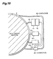
- Fig. 10 illustrates the details of one portion of the apparatus shown in foregoing Fig. 9, i.e., the details of the inside of container 40.
- the light source 10, wavelength selector 11, first photodetector 14 1 , second photodetector 14 2 , and light guides 12, 13 1 , 13 2 are built in the container 40 and the modulated light of the predetermined wavelengths ⁇ 1 , ⁇ 2 , ⁇ 3 emitted from the light source 10 is subjected to wavelength selection by the wavelength selector 11 to be incident through the light guide 12 to the head 2.
- the three wavelengths are properly selected referring to the absorption spectra of hemoglobin shown in aforementioned Fig. 3.
- the light having diffuse-propagated inside the head 2 is received by the light guides 13 1 , 13 2 placed at the positions (photodetection positions) the distances r 1 and r 2 apart from the aforementioned light incidence position, is converted into electric signals by the first photodetector 14, and second photodetector 14 2 , and is amplified if necessary.
- the power (power supply) and various signals are transmitted through connector 43 and signal cable 42 attached to the container 40 from the external device 41 and to the external device 41.
- the signal detecting section, first arithmetic section, second arithmetic section, and display/recording section (none of which is illustrated) placed in the external device 41 perform the same signal detection and arithmetics for the three wavelengths and the two photodetection distances as in the above third embodiment.
- two simultaneous equations of the four types similar to aforementioned Eq. (15), hold for signals obtained at the wavelengths ⁇ 1 and ⁇ 2 and at the wavelengths ⁇ 1 and ⁇ 3 , signals obtained at the wavelengths ⁇ 1 and ⁇ 2 and at the wavelengths ⁇ 2 and ⁇ 3 , or signals obtained at the wavelengths ⁇ 1 and ⁇ 3 and at the wavelengths ⁇ 2 and ⁇ 3 .
- the above arithmetic processes are carried out at high speed by microcomputers or the like incorporated in the first and second arithmetic sections. Further, the signals in the container 40 can be converted into radio waves or light signals and they can be transmitted to the external device 41 without intervention of signal cable.
- the light source, light incidence section, and photodetection means may be selected from those listed in the first embodiment.
- the aforementioned interface material may be utilized well.
- the interface material having the scattering coefficient and absorption coefficient nearly equal to those of the measured object may be positioned between the head 2 and the wavelength selector 11 and between the head 2 and the photodetectors 14 1 and 14 2 .
- the apparatus as described can be used not only for the measurement of information in the brain, but also for measurement or monitoring of concentration of oxygenated hemoglobin in a leg muscle of a man in marathon, for example.
- the fifth embodiment is arranged so that the modulated light of the three wavelengths ⁇ 1 , ⁇ 2 , ⁇ 3 emitted from the light source in the above fourth embodiment is replaced by modulated light of a predetermined repetition frequency of an arbitrary waveform.
- the fourth embodiment used the sinusoidal modulated light of the predetermined angular frequency, but the modulated light may be of any waveform if it contains a specific frequency component, whereby the approach of the fourth embodiment can be applied as it is, to the specific frequency component contained in the light.
- the approach of the fourth embodiment can be applied to either one frequency component as it is.
- the performance that the modulated light of the predetermined repetition frequency is required to have is the stable repetition frequency and stable light intensity.
- the absorption information measuring methods and apparatus of scattering medium enable to efficiently measure the concentration change or the absolute concentration of absorptive constituent inside the scattering medium of an arbitrary shape comprised of non-reentrant surfaces. Further, the present invention enables to measure the spatial distribution of the concentration change and the temporal change and spatial distribution of concentration. Further, since the methods and apparatus of the present invention utilize the modulated light, the utilization factor of light is high and signal-to-noise ratios are large, thus achieving the high measurement accuracy. Therefore, the methods and apparatus of the present invention allow accurate and efficient real-time measurements of oxygen amounts in the brain, oxygen amounts in a leg muscle of a man under motion, concentrations of absorptive constituents in a living tree, and so on.
Description
- The present invention relates to an absorption information measuring method and apparatus of scattering medium and, more particularly, to a method and apparatus for measuring a temporal change or a spatial distribution of concentration of an absorptive constituent in a scattering medium having non-reentrant surfaces. The invention further concerns a method and apparatus for measuring a concentration of an absorptive constituent inside the scattering medium by use of light of plural wavelengths.
- There are very strong demands for non-invasive and precise measurements of absorption information including a concentration of a specific absorptive constituent inside a scattering medium like a living body, a temporal change or a spatial distribution thereof, and so on. Attempts of various methods have been made heretofore, including methods using continuous wave light (cw light) and modulated light (for example, pulsed light, square-wave light, sine-wave modulated light, etc.), methods utilizing light of different wavelengths (multi-wavelength spectroscopy), and so on.
- These conventional technologies, however, have developed no methods and apparatus capable of accurately measuring the concentration of the specific absorptive constituent inside yet for tissues and organs having various shapes like the living body or for objects having individual differences of shape though being tissues or organs of a same kind. This is a serious problem in non-invasive measurements of living body utilizing light, and improvements therein are strongly desired.
- Light incident to the scattering medium like the living body propagates inside as scattered and absorbed therein, and then part thereof emerges from its surface. Since the outside of the scattering medium is normally air, the light emerging from the surface is dispersed in the free space. The light emerging from the surface as described above is detected in measurements of internal information of scattering medium. At this time the propagating light spreads throughout the entire region of scattering medium and is dispersed from the whole surface to the outside. Therefore, when the output light is detected at a specific position in the surface, the quantity or a time-resolved waveform of detected light greatly varies with change in the shape of medium, for example, depending upon whether it is a sphere or a rectangular parallelepiped.
- In order to enhance the measurement accuracy in the cases as described above, it is necessary to sufficiently understand the behavior of light inside the scattering medium. Recently, the behavior of light inside the scattering medium is analyzed, tested, or investigated by Monte Carlo simulations with a computer. It is also known that the behavior can be described and analyzed accurately to some extent by the photon diffusion theory. The Monte Carlo simulations, however, require an extremely long calculation time and do not allow calculation of a concentration of a specific absorptive constituent inside the scattering medium from their results. In utilizing the photon diffusion theory, it is necessary to set boundary conditions for solving the photon diffusion equation. However, since the boundary conditions differ greatly depending upon the shape of scattering medium, new boundary conditions must be set to solve the photon diffusion equation for every change in the shape of scattering medium, in order to achieve accurate measurement. Scattering media for which the boundary conditions can be set accurately to some extent are limited to very simple shapes such as an infinite space, a semi-infinite space, an infinite cylinder, or a slab spreading infinitely and having a finite thickness. As a result, use of approximate boundary conditions is indispensable to measurements of living tissues having complicated shapes, which is a cause to produce large measuring errors.
- The above problems are also discussed, for example, in the recent literature: Albert Cerussi et al., "The Frequency Domain Multi-Distance Method in the Presence of Curved Boundaries," in Biomedical Optical Spectroscopy and Diagnostics, 1996, Technical Digest (Optical Society of America, Washington DC, 1996) pp. 24-26.
-
US patent application 5,122,974 relates to methods and apparatus for studying photon migration using signal modulation techniques such as time, frequency and phase modulation. The photon migration data may then be converted, using the principles of time-resolved spectroscopy, to determine the concentration of an absorptive constituent in a scattering medium, such as the concentration of hemoglobin in a brain of other tissue. -
US patent 5,424,832 relates to an apparatus and method for qualitative and quantitative optical measurements by using multiple light scattering for exposing a sample to a modulated laser beam. The light beam is modulated at a fundamental frequency and at a plurality of integer harmonics thereof. Modulated light is returned from the sample and preferentially detected at cross frequencies at frequencies slightly higher than the fundamental frequency and at integer harmonics of the same. The received radiance is compared against a reference signal to provide a measure of the phase lag of the radiance and modulation ratio relative to a reference beam. In this way the absorption and scattering coefficients are determined together with a concentration of the active substance in the sample. - As described above, there are no measuring methods of absorption information sufficient to be systematically applied to scattering media of different shapes yet and it was extremely difficult for the conventional technologies to accurately and efficiently measure the concentration of a specific absorptive constituent or the like in the scattering media of different shapes systematically.
- The present invention has been accomplished in view of the problems in the conventional technologies described above and an object of the invention is to newly disclose a method for describing the behavior of light inside the scattering media of different shapes (basic relations) and to provide a measuring method and measuring apparatus of absorption information inside the scattering medium, realizing measurements of change, absolute value, or the like of concentration of a specific absorptive constituent in the scattering media of various shapes by use of the relations, greatly improving the measurement accuracy thereof, and being capable of efficiently measuring a temporal change or a spatial distribution thereof.
- In accordance with the invention, there are provided methods and apparatuses for measuring absorption information in accordance with the independent claims.
- In the methods of the present invention, using the difference between absorption coefficients, a difference of concentration of an absorptive constituent can be quantified based on a predetermined relation among this difference between absorption coefficients, an absorption coefficient per unit concentration of the absorptive constituent, and the difference of concentration of the absorptive constituent.
- In the second arithmetic section of an apparatus according to the present invention, using the difference between absorption coefficients, a difference of concentration of an absorptive constituent can be calculated based on a predetermined relation among this difference between absorption coefficients, an absorption coefficient per unit concentration of the absorptive constituent, and the difference of concentration of the absorptive constituent.
- The present invention will be more fully understood from the detailed description given hereinbelow and the accompanying drawings, which are given by way of illustration only and are not to be considered as limiting the present invention.
- Further scope of applicability of the present invention will become apparent from the detailed description given hereinafter. However, it should be understood that the detailed description and specific examples, while indicating preferred embodiments of the invention, are given by way of illustration only, since various changes and modifications within the scope of the invention will be apparent to those skilled in the art from this detailed description.
-
- Fig. 1 is a schematic diagram to show the track of the photon having propagated inside the scattering medium.
- Fig. 2 is a schematic diagram of the configuration of the apparatus in the first embodiment according to the present invention.
- Fig. 3 is a graph to show the absorption spectra of hemoglobin and myoglobin.
- Figs. 4A, 4C and 4E are schematic diagrams each showing a method for generating sinusoidal modulated light.
- Figs. 4B, 4D and 4F are schematic diagrams each showing sinusoidal modulated light generated by a method shown in Figs. 4A, 4C or 4E.
- Figs. 5A, 5B, 5C and 5D are schematic diagrams each showing a light incidence method to the scattering medium.
- Figs. 6A, 6B and 6C are schematic diagrams each showing a light receiving method.
- Fig. 7 is a schematic diagram of the configuration of the apparatus in the second embodiment according to the present invention.
- Fig. 8 is a schematic diagram of the configuration of the apparatus in the third embodiment according to the present invention.
- Fig. 9 is a schematic diagram of the configuration of the apparatus in the fourth embodiment according to the present invention.
- Fig. 10 is a schematic diagram of the configuration of the light incidence and detection section of the apparatus in the fourth embodiment.
- First described is the principle of the present invention. The knowledge described below is one first disclosed by the present inventor.
- Various constituents in a living tissue are mixed microscopically inhomogeneously, i.e., are localized. However, considering the spectral analysis of living tissue from the medical and biological viewpoints, most cases are satisfied by quantifying a specific constituent contained in the living tissue from an optical characteristic in the macroscopic view of complex living tissue, i.e., from a measurement value measured as a mean value. This idea is seen in the impulse response and system function of black box in the linear system theory. Let us consider below such an example that a homogeneous scattering medium is assumed, light is made incident to a surface thereof, light having propagated inside the scattering medium is received at another position to obtain a measurement signal, and a concentration of an absorptive constituent contained inside is quantified from the measurement signal. In this case, the contours of the scattering medium are assumed to be those having non-reentrant surfaces; that is, the medium is of an arbitrary shape that keeps diffuse light emerging from the medium from reentering the medium. Further, the incident light is assumed to be one having an arbitrary time-resolved waveform. In this case, the incident light of the arbitrary time-resolved waveform can be expressed, as apparent from the Fourier transform principle, by superposition of light components modulated at various frequencies, and thus the following discussion will be given in the frequency aspect, considering the incident light of an arbitrary modulation frequency.
- Fig. 1 shows an example of track of a detected photon which has propagated inside a scattering medium or a scattering absorptive body. The light is strongly scattered by scattering constituents, so that the optical path of the photon is bent in a zig-zag pattern. At this time the Lambert-Beer's law holds for the zig-zag flight pathlength and the intensity of propagating light is exponentially attenuated against the zig-zag flight pathlength (cumulative length). Namely, the flight pathlength (optical pathlength) is given by 1 = ct, where c is the velocity of light in the medium and t is the time of flight, and the survival rate of the photon is given by exp(-cµat), where µa is the absorption coefficient. When the light (light beam) is incident at position P and is detected at position Q, photons having passed through various optical paths are detected, and the quantity of detected light being the sum of those photons, which is the survival rate, is proportional to exp(-cµat).
- Accordingly, light output h(t) obtained with incidence of impulse light into the scattering medium, which is the impulse response, is given as follows.


- Here, J is a term representing the impulse response or output light, s(µs, t) a term representing a response when the absorption coefficient µa = 0 (which is a response where only scattering exists), and the exponent term exp(-cµat) a term representing attenuation due to the absorption coefficient µa. The all functions are time-causal functions which become zero when t < 0. Further, µs is the scattering coefficient.
- The Fourier transform of impulse response h(t) indicates the system function. Considering the Fourier transform of Eq. (1.1) while taking it into consideration that the impulse response h(t) is the time-causal function, we can derive the following system function H(ω).

- Here, R(cµ a, ω) and X(cµa, ω) are the real part (sine component) and the imaginary part (cosine component), respectively, and A(cµa, ω) and Φ(cµa, ω) are the amplitude and phase, respectively. A phase delay is the phase with the opposite sign.
- Then substituting Eq. (1.1) into Eq. (2) and arranging it, the following equations are derived. These equations are called as the Cauchy-Riemann equations in the complex function theory.


- It can be further proved that the following relations also hold when Eq. (3.1) and Eq. (3.2) hold.


- For calculating the absorption coefficient µa, which is the primary object of the present invention, either one of Eqs. (3.1) to (4.2) may be used. Specifically, it is preferred to use integrations of these equations over µa, i.e., the following equations obtained from the above equations.


- Here, the second terms in the right sides of Eqs. (5.1) to (5.4) are integration constants, each of which indicates a value at µa = 0. Described below are methods for calculating information concerning absorption from measured values by use of Egs. (5.1) to (5.4).
- Let us consider a case wherein a medium contains one type of absorptive constituent and the absorption coefficient µa thereof has changed from µa1 to µa2 with change in the concentration thereof. Supposing Eqs. (5.1) to (5.4) hold before and after the change and s(µs, t) is invariant before and after the change, the following equations are derived using µa1 and µa2 before and after the change.


- With normal scattering media the scattering characteristics may be considered not to change with change in the concentration of absorptive constituent. This is just as if ink is mixed in milk.
- Next applying the mean value theorem, the following equations are obtained from Eqs. (6.1) to (6.4).


- Here, µxi (i = 1, 2, 3, 4) denotes a suitable value satisfying the condition of µa1 ≤ µxi ≤ µa2 or µa1 ≥ µxi ≥ µa2.
- The above demonstrates that once we know the modulation angular frequency ω of modulated light used in measurement and inclinations of the four parameters, ∂x/∂ω, ∂R/∂ω, ∂Φ/∂ω, ∂lnA/∂ω, at µa = µxi, we can calculate the difference between the absorption coefficients before and after the change, µa2 - µa1, from the values of X, R, A, Φ before and after the change (which can be obtained all from observed values) and the value of c determined by the refractive index of the medium and the velocity of light therein.
- In the above case, the above inclinations of the four parameters Bi (i = 1, 2, 3, 4) at µa = µxi, ∂Bi/∂ω|µxi, can be expressed as follows by use of the inclinations at µa1 and at µa2.

- Here, pi is a suitable value satisfying the condition of 0 ≤ pi ≤ 1. In this case, since Bi are monotonic functions and the inclinations at µa1 and at µa2 are normally nearly equal, pi = 1/2 may be assumed.
- Further, inclinations of the four parameters at the modulation angular frequency ω1, ∂Bi/∂ω|ω1, can be measured by use of modulated light having two modulation angular frequency components satisfying ω = ω1 ± Δω/2 (> 0). This relation can be expressed by the following equation.

- Accordingly, the respective inclinations ∂Bi/∂ω of Eqs. (7.1) to (7.4) become as follows when Eq. (9) is substituted into Eq. (8) and pi = 1/2.

The above described the method for precisely obtaining ∂Bi/∂ω. - On the other hand, it is empirically known that the approximation of ∂Φ/∂ω ≒ Φ/ω can be applied at low modulation frequencies (for example, at f = ω/2π = 100 MHz or less in measurements of living bodies or the like). This can be derived by analyzing the response of a scattering medium having a simple shape by use of the photon diffusion equation. More specifically, boundary conditions are determined for a semi-infinite medium or a medium of a rectangular parallelepiped having a size over a certain level, and the photon diffusion equation is solved under the determined boundary conditions to obtain the inclinations ∂Bi/∂ω in the right sides of Eqs. (7.1) to (7.4), whereby the approximate equations of the inclinations ∂Bi/∂ω can be derived. For example, in the case of the relation of Eq. (7.3), approximation of ∂Φ/∂ω ≒ Φ/ω holds. Accordingly, at low modulation frequencies, ∂Φ/∂ω ≒ Φ/ω may be applied to Eq. (7.3). In this case, forgoing Eq. (7.3) is changed to the following.

- Here, p is a coefficient similar to that used in Eq. (8) and p = 1/2 may be normally assumed herein. It is clear that for foregoing Eqs. (7.1), (7.2), and (7.4), approximate equations corresponding to the respective equations can also be derived in the same manner as above.
- For calculating concentration change ΔV of absorptive constituent, the following equation derived from the Lambert-Beer's law is applied.

Here, ε is an absorption coefficient (or an extinction coefficient) per unit concentration of absorptive constituent, which can be measured by a spectrometer. Changes in concentrations of two or more types of absorptive constituents can also be measured using light having two or more wavelengths by the above method. - The above description clarified the method for measuring the concentration change of absorptive constituent inside the scattering medium from Eqs. (7.1) to (7.4) and Eq. (12). It is also possible to conduct the above measurement using modulated light of different wavelengths. Accordingly, a temporal change of concentration of absorptive constituent in the scattering medium can be measured while fixing the measuring site. This measurement can be applied to measurements of temporal change of concentration of hemoglobin in a certain portion, and the like. (Measurements of concentration change of absorptive constituent or spatial distribution of concentration difference thereof from reference value)
- It is also possible to measure a distribution of temporal change of concentration of absorptive constituent inside the scattering medium by carrying out the above-stated measurement while moving or scanning the measuring site. In addition, it is also possible to measure a distribution of difference of concentration of absorptive constituent inside the scattering medium with respect to a reference value, by moving or scanning the measuring site along a measured object while fixing the positions of light incidence and light reception relative to each other, performing measurements during the movement, and taking a measured value at an arbitrary position as the reference value. Such measurements can be applied to photo-mammography for diagnosis of breast cancer. These measurements according to the present invention can be applied to scattering media of various shapes having non-reentrant contours, and specific application examples include fluoroscopes, optical CT, clinical monitors utilized in surgery or cure, and so on, as well as the photo-mammography. These examples utilize such methods as light reception at multiple points, scanning of light incidence position and light receiving position, and time-sharing measurement as occasion may demand.
- The following describes the measurement with modulated light (of modulation angular frequency ω) from light having two wavelengths λ1 and λ2, i.e., the dual-wavelength spectrophotometry.
- First, let us assume that a scattering medium containing one absorptive constituent has the absorption coefficient µa1 for light of wavelength λ1, and µa2 for light of wavelength λ2. It is also assumed that the scattering coefficients of the medium for the light of wavelengths λ1 and λ2 are equal or nearly equal to each other. Such conditions are realized readily by selecting the wavelengths used in measurement. Under these circumstances, similar equations to Eqs. (6.1) to (6.4) are derived from forgoing Eqs. (5.1) to (5.4). However, the definition of absorption coefficients µa1 and µa2 is different from that in the case of Eqs. (6.1) to (6.4) and µa1 and µa2 herein mean the absorption coefficients of the measured medium for the light of wavelengths λ1 and λ2. Further, equations similar to foregoing Eqs. (7.1) to (7.4) are obtained and the difference between the absorption coefficients of the measured medium for the light of the two wavelengths, µa2 - µa1, can be obtained by use of these equations.
- The concentration V of a specific absorptive constituent is calculated from the below equation, using the absorption coefficients (or extinction coefficients) per unit concentration of the specific absorptive constituent for the light of wavelengths λ1 and λ2, ε1 and ε2.

Here, values of ε1 and ε2 can be preliminarily measured by the electrometer. Accordingly, the absolute concentration V of absorptive constituent can be measured in the exactly same manner as the aforementioned measurement of concentration change of absorptive constituent. - Considering the wavelength dependence of scattering coefficient, for example, the equation corresponding to foregoing Eq. (6.3) becomes as follows by use of the scattering coefficients µs1 and µs2 of the measured medium for the light of the wavelengths λ1 and λ2.

- In this equation, however, the wavelength dependence of ∂Φ/∂ω is ignored. Further, b2/b1 is a ratio of intensities of incident light at the wavelengths λ1 and λ2 and A(µs1, 0, ω) and A(µs2, 0, ω) are values at µs = 0. By this, the following equation is attained from Eq. (14) as Eq. (7.3) was.

- Also in this case, similarly as in Eq. (7.3), µx is a suitable value satisfying the condition of µa1 ≤ µx ≤ µa2 or µa1 ≥ µx ≥ µa2. By setting b2/b1 = 1 and k = 1, this Eq. (15) becomes equal to foregoing Eq. (7.3). The coefficient b2/b1 can be set to b2/b1 = 1 by adjusting the intensity of incident light. It is also possible to estimate the value of b2/b1 from a measured value of the intensity of light source. Further, k = µ's1/µ's2 can be derived by solving the photon diffusion equation for a medium of a simple shape. Here, µ's1 and µ's2 are transport scattering coefficients at the wavelengths λ1, and λ2' respectively. Accordingly, the difference between the absorption coefficients, µa2 - µa1, of the medium containing the specific absorptive constituent for the light of the two wavelengths can be calculated from Eq. (15). Then the concentration V of the specific absorptive constituent can be further calculated from Eq. (13).
- If two-point measurements for receiving output light at two positions are carried out in the above dual-wavelength spectrophotometry, a new relation will be attained by eliminating the coefficient b2/b1 described above. Namely, the coefficient b2/b1 can be eliminated by utilizing no dependence of the coefficient b2/b1 on the detection positions. Further, it is a matter of course that the above-stated method can be expanded to multiple-wavelength spectrophotometry using light having three or more wavelengths.
- The measurement of spatial distribution of concentration of absorptive constituent is achieved by performing the above-stated measurement at multiple points. This measurement according to the present invention enables measurements with the scattering media of various shapes having non-reentrant contours. Specific application examples include the photo-mammography, fluoroscopes, optical CT, and so on. These examples employ the methods such as the light reception at multiple points, scanning of light incidence position and light receiving position, and the time-sharing measurement as occasion may demand. The features of these measurements are the capability of measuring the spatial distribution of concentration of specific absorptive constituent, the spatial distribution of difference between absorptive constituents of the measured medium for the light of two wavelengths, the spatial distribution of temporal change of concentration of specific absorptive constituent, and so on, as described above. These pieces of information are utilized in the clinical monitor, diagnosis or analysis, and surgery or cure.
- Embodiments of the present invention will be described with reference to the accompanying drawings. It is, however, noted that in the following description the same elements will be denoted by the same reference symbols and redundant description will be omitted.
- Fig. 2 shows the first embodiment of the apparatus of the present invention for carrying out the method of the present invention and illustrates the configuration of
apparatus 1 for measuring the temporal change of concentration of absorptive constituent inside scatteringmedium 2. In this configuration ofapparatus 1, modulated light of predetermined wavelength λ and modulation frequency f (the modulation angular frequency ω = 2πf) is made incident on position P (light incidence position) in the surface of scattering medium 2 and the light having propagated inside thescattering medium 2 is received at another position Q (photodetection position) in the surface. Then a change in the concentration of an absorptive constituent inside the scattering medium is quantified by repetitively carrying out measurements. In this case, the change in the concentration of the absorptive constituent can be quantified by taking a concentration of the absorptive constituent in the first measurement as a reference value. The measuringapparatus 1 is integrally housed in one casing. - A laser diode or the like is used as
light source 10, and the modulated light of wavelength λ and predetermined modulation angular frequency ω is generated thereby. In this case, the wavelength is selected depending upon the scattering medium and the absorptive constituent to be measured. In measurements of living body, oxygenated and deoxygenated hemoglobin and oxygenated and deoxygenated myoglobin is often measured and absorption spectra of those absorptive constituents are shown in Fig. 3. Therefore, the light of 600 nm to 1.3 µm is normally used in the measurements of living body. The modulation frequency f is properly selected in the range of 1 MHz to 1 GHz. This modulation frequency is preferably as high as possible in measurements of spatial distribution. In the following, f = 100 MHz. Thelight source 10 can also be selected from the light-emitting diode, HeNe laser, and so on, as well as the laser diode. - Sinusoidal modulated light of the predetermined angular frequency is generated by current modulation of the laser diode as shown in Figs. 4A and 4B. The sinusoidal modulated light can also be generated by beat of two cw lasers or by use of an optical modulator, as shown in Figs. 4C and 4D and in Figs. 4E and 4F.
- The modulated light emitted from the
light source 10 is incident throughlight guide 12 to the surface of scattering medium 2, which is a measured object. The space between thelight guide 12 and thescattering medium 2 is very small in the embodiment of Fig. 2. In practice, however, this space may be widened and may be filled with a liquid substance or a jelly substance (which will be called an interface material) having the refractive index and scattering coefficient nearly equal to those of thescattering medium 2. Namely, the modulated light propagates in this interface material to enter the measured object without posing any problem. If reflection on the surface of scattering medium is problematic, influence of the surface reflection or the like can be decreased by properly selecting the interface material. - The modulated light having propagated inside the scattering medium is received by
light guide 13 located at position Q the distance r apart from the aforementioned light incidence position P. The interface material may also be employed herein for the same reason as above.Photodetector 14 converts an optical signal of the light received into an electric signal, amplifies it if necessary, and outputs a measurement signal. Thephotodetector 14 may be selected from a phototube, a photodiode, an avalanche photodiode, a PIN photodiode, and so on, in addition to a photomultiplier tube. In selection of the photodiode, it needs to have the spectral sensitivity characteristics for detecting the light of predetermined wavelengths and necessary time response speed. For weak light signals, a high-gain photodetector is used. Further, the time correlation photon counting method for counting photons may be applied. The other places than the light receiving surface of photodetector are desirably constructed in structure for absorbing or intercepting the light. - Signal detecting
section 15 detects a signal of the predetermined modulation frequency component from the aforementioned measurement signal. Specifically, the monodyne detection, heterodyne detection, or lock-in detection, well known, is used. In this case, thesignal detecting section 15 utilizes a signal synchronized with the modulated light emitted from thelight source 10 as occasion demands. Firstarithmetic section 16 calculates the amplitude A and the inclination (derivative) ∂Φ/∂ω of phase Φ against the modulation angular frequency from the foregoing signal of the predetermined modulation frequency component. Then the above measurement is carried out repetitively. Now, let us consider the m-th and (m + 1)-th measurements. - Second
arithmetic section 17 substitutes two said amplitudes Am and Am+1 obtained in the m-th and (m + 1)-th measurements, and an inclination of phase ∂Φ/∂ω|µx3 obtained from two said inclinations of phase into aforementioned Eq. (7.3) to calculate a change amount of absorption coefficient of scattering medium 2, µa(m+1) - µam (primary information), and further calculates a change amount of absorptive constituent by use of aforementioned Eq. (12). - At this time, for calculating the inclination of phase ∂Φ/∂ω|µx3, aforementioned Eq. (8) is used and sufficient accuracy is achieved with p = 1/2. Since f = 100 MHz, the approximation ∂Φ/∂ω ≒ Φ/ω may be applied as described above. In the case of f > 100 MHz, measurements are conducted with the modulated light of two modulation angular frequencies ω = ω1 ± Δω/2 (> 0) and ∂Φ/∂ω|µx3is calculated using aforementioned Eq. (10). These arithmetic processes are executed at high speed by microcomputers incorporated in the first and second arithmetic sections.
- The second
arithmetic section 17 has a function to store the concentration information of absorptive constituent thus obtained and display/recording means 18 is a section for displaying or recording these information pieces. - The above arrangement used the modulated light of one wavelength, but modulated light of two or more wavelengths may also be utilized in practice. Further, it is also possible to make the light incident to one position and to detect the propagating light at two or more positions. These may be detected in parallel or in time division.
- The means for making the light incident to the
scattering medium 2, instead of thelight guide 12 shown in Fig. 2, may be selected from a method with a condenser lens (Fig. 5A), a method using an optical fiber (Fig. 5B), a method utilizing a pinhole (Fig. 5C), a method for making the light incident from inside a body like a gastrocamera (Fig. 5D), and so on. A thick beam of light may also be made incident to thescattering medium 2. In this case, the light source may be regarded as an array of plural spot light sources. - The means for detecting the light having diffuse-propagated inside the
scattering medium 2, other than the method using thelight guide 13 shown in Fig. 2, may be selected from a method for directly detecting it (Fig. 6A), a method using an optical fiber (Fig. 6B), a method using a lens (Fig. 6C), and so on. - The above first
arithmetic section 16 was described as to the case for calculating the amplitude A and inclination ∂Φ/∂ω of phase Φ against modulation angular frequency from the signal of the predetermined modulation frequency component. However, it may also calculate from the signal of the predetermined modulation frequency component either one combination of (i) the sine component with the inclination (derivative) of cosine component against modulation angular frequency, (ii) the cosine component with the inclination (derivative) of sine component against modulation angular frequency, or (iii) the phase with the inclination (derivative) of natural logarithm of amplitude against modulation angular frequency, as described previously. In that case, "amplitude A, inclination ∂Φ/∂ω of phase Φ against modulation angular frequency, and Eq. (7.3)" inabove Embodiment 1 should read (i) "sine component, inclination (derivative) of cosine component against modulation angular frequency, and Eq. (7.1)," (ii) "cosine component, inclination (derivative) of sine component against modulation angular frequency, and Eq. (7.2)," or (iii) "phase, inclination (derivative) of natural logarithm of amplitude against modulation angular frequency, and Eq. (7.4)." Accordingly, the first embodiment stated herein can quantify the change of concentration of absorptive constituent according to Eqs. (7.1) to (7.4). - Measurements are carried out in the same manner as in above
Embodiment 1 except for synchronous scanning of the light incidence position P and photodetection position Q of the modulated light relative to thescattering medium 2, and the reference value is a concentration of the absorptive constituent at an arbitrary position, whereby a spatial distribution of concentration difference from the reference value can be measured. Also in this case, similarly as in aboveEmbodiment 1, the spatial distribution of difference of concentration of absorptive constituent from the reference value can be measured using Eqs. (7.1) to (7.4). - Fig. 7 shows the second embodiment of the apparatus of the present invention for carrying out the method of the present invention and illustrates the configuration of apparatus 1 (mammography) for measuring the spatial distribution of concentration of absorptive constituent inside the
scattering medium 2 like the breast. In Fig. 7 the components having the same functions as those shown in Fig. 2 associated with the aforementioned first embodiment are denoted by the same symbols. The modulated light of predetermined wavelength λ and modulation frequency f (the modulation angular frequency ω = 2πf) is made incident to the surface of scattering medium 2 and the light having propagated inside the scattering medium is received at the position in the surface on the opposite side. On this occasion, the measurement is conducted while synchronously moving the incidence position and photodetection position of the modulated light. Then, for example, using a concentration of the absorptive constituent in the measurement at the first position (the first light incidence position and first photodetection position) as the reference value, the spatial distribution of concentration difference of absorptive constituent can be measured. - The
apparatus 1 shown in Fig. 7 associated with the second embodiment has firstmechanical section 30 for lightly nipping thescattering medium 2 in parallel. Namely, the firstmechanical section 30 enables thescattering medium 2 like the breast to be measured in a slightly flattened state. This firstmechanical section 30 is equipped with secondmechanical section 31 for synchronously moving the incidence position and photodetection position of the modulated light. Then this secondmechanical section 31 outputs position signals indicating scanning positions and the position signals are supplied to the display/recording section 18 to be utilized for display or recording of the spatial distribution.Wavelength selector 11 is disposed in the post-stage oflight source 10 for emitting the modulated light, so that modulated light of a desired wavelength can be selected with necessity. The other portions are the same as in the apparatus of the first embodiment described above. - The above arrangement used the modulated light of one wavelength, but modulated light of two or more wavelengths may be used in practice. Further, it is also possible to make the light incident to one light incidence position and to detect the propagating light at two or more photodetection positions simultaneously or in time division.
- Fig. 8 shows the third embodiment of the apparatus of the present invention for carrying out the method of the present invention and illustrates the configuration of the apparatus for measuring the concentration of absorptive constituent inside the
scattering medium 2. In Fig. 8 the components having the same functions as those in Fig. 2 associated with the first embodiment and in Fig. 7 associated with the second embodiment are denoted by the same symbols. This configuration is arranged to use the modulated light of two wavelengths λ1 and λ2 and two photodetection distances r1 and r2. In this case, Eq. (15) described previously holds for each of measurements at the two photodetection distances r1 and r2. Accordingly, the difference between the absorption coefficients of the measured scatteringmedium 2 for the light of two wavelengths, µa2 - µa1, can be obtained by eliminating the coefficient b2/b1 in Eq. (15) from simultaneous equations comprised of two equations based on Eq. (15). In this example, since the modulated light of two different wavelengths, at which the scattering coefficients are equal to each other or are regarded as equal to each other, is made incident to the scattering medium, k in aforementioned Eq. (15) can be k = 1 and lnk is eliminated therefrom. For media of simple shape, k = µ's1/µ's2 may be assumed as described previously. From the above, the difference µa2-µa1between the absorption coefficients of the medium containing a specific absorptive constituent for the light of the two wavelengths is calculated from Eq. (15) and the concentration of the absorptive constituent in the scattering medium can be quantified based on the relation shown in Eq. (13). - The
light source 10 is a laser diode or the like and generates the modulated light of the two different wavelengths λ1 and λ2 and, for example, the modulation frequency f = 100 MHz. The modulated light from thelight source 10 is subjected to wavelength selection by thewavelength selector 11 and is guided through thelight guide 12 to the surface of scattering medium 2 being the measured object. In this case, the apparatus may employ a method for making the modulated light beams of two wavelengths incident simultaneously and in this arrangement thewavelength selector 11 is omitted. - The space between the
light guide 12 and thescattering medium 2 is very small in the embodiment of Fig. 8. In practice, however, this space may be widened and it may be filled with a liquid substance or a jelly substance (which will be called an interface material) having the refractive index and scattering coefficient nearly equal to those of thescattering medium 2, as in the first embodiment. Namely, the modulated light propagates in this interface material to enter the measured object without posing any problem. If reflection on the surface of scattering medium is problematic, influence of the surface reflection or the like can be decreased by properly selecting the interface material. - The light having propagated inside the
scattering medium 2 is received by first and second light guides 131, 132 placed at the positions (photodetection positions) the distances r1 and r2 apart from the light incidence position. The interface material may also be used herein for the same reason as above. - The
first photodetector 141 andsecond photodetector 142 convert respective light signals of the light received into electric signals, amplify them if necessary, and output measurement signals as to the measurements at the two photodetection distances r1, and r2 Thephotodetectors photodetectors scattering medium 2. - The
signal detecting section 15 and firstarithmetic section 16 execute the following arithmetic based on the foregoing measurement signals respectively obtained in the measurements at the two photodetection distances r1 and r2. First, thesignal detecting section 15 detects signals of the respective predetermined modulation frequency components from the measurement signals respectively obtained for the modulated light of the two wavelengths. In this case, thesignal detecting section 15 utilizes a signal synchronized with the modulated light emitted from thelight source 10 as occasion may demand. Next, the firstarithmetic section 16 calculates the amplitudes A and inclinations (derivatives) ∂Φ/∂ω of phase against modulation angular frequency from the respective signals of the predetermined modulation frequency components obtained for the modulated light of the two wavelengths. - The second
arithmetic section 17 substitutes the above respective amplitudes A obtained at the two photodetection distances for the modulated light of the two wavelengths, and the inclinations of phase ∂Φ/∂ω|µx obtained from the above respective inclinations of phase into aforementioned Eq. (15), solves simultaneous equations comprised of two equations obtained for the measurements at the two photodetection distances r1 and r2, calculates the difference µa2 - µa1 (primary information) between the absorptive coefficients of thescattering medium 2 for the light having the two wavelengths, and further calculates the concentration of the absorptive constituent by use of aforementioned Eq. (13). For calculating the inclination of phase ∂Φ/∂ω|µx3, aforementioned Eq. (8) is applied and sufficient accuracy is secured with p = 1/2. Since f = 100 MHz, approximation ∂Φ/∂ω ≒ Φ/ω may be applied as described above. In the case of f > 100 MHz, measurements are conducted with the modulated light of the two modulation angular frequencies ω = ω1 ± Δω/2 (> 0) and ∂Φ/∂ω|µx3 is calculated using aforementioned Eq. (10). These arithmetic processes are carried out at high speed by microcomputers incorporated in the first and second arithmetic sections. - The above second
arithmetic section 17 has a function to store the concentration information of absorptive constituent thus obtained and the display/recording means 18 is a section for displaying or recording these. - In the case wherein incident light intensities of the modulated light of the two wavelengths λ1 and λ2 to the
scattering medium 2 are equal to each other or can be controlled so as to be equal, thesecond photodetector 142 can be omitted. In this case, the coefficient b2/b1 in aforementioned Eq. (15) becomes b2/b1 = 1 and ln(b2/b1) is eliminated therefrom. Thus, the difference µa2 - µa1 (primary information) between the absorption coefficients of scattering medium 2 for the light of the two wavelengths can be calculated directly from Eq. (15) and the concentration of absorptive constituent can be further calculated using aforementioned Eq. (13). - The above described the method for making the light incident to one position and detecting the light at the two other positions. In practice, however, light beams of different wavelengths may be made incident at two positions and the light may be detected at another position in parallel or in time division.
- The above third embodiment may employ either the method for making the light including beams of different wavelengths incident or the method for making the beams of different wavelengths incident in time division and using each beam. In the former case, either one method is selected from a method for forming coaxial beams of the light of the different wavelengths and selecting the wavelength by a wavelength selecting filter provided immediately before the light incidence position, a method for making the beams incident to the scattering medium as they are and selecting the wavelength by a wavelength selecting filter provided immediately before the photodetector, a method for splitting each detected light into two beams, subjecting them to wavelength selection, and detecting them in parallel by totally four photodetectors. In the latter case, either one device may be used from a light beam switching device using a mirror on the light source side, a wavelength switching device using a filter, a light switching device using an optical switch, and so on. The means for making the light incident to the scattering medium and the means for detecting the light having diffuse-propagated inside the scattering medium may be selected from those listed in the first embodiment.
- The above first
arithmetic section 16 was described as to the case for calculating the amplitude A and inclination ∂Φ/∂ω of phase Φ against modulation angular frequency from the signal of the predetermined modulation frequency component. However, it may calculate from the signal of the predetermined modulation frequency component either one combination of (i) the sine component with the inclination (derivative) of cosine component against modulation angular frequency, (ii) the cosine component with the inclination (derivative) of sine component against modulation angular frequency, or (iii) the phase with the inclination (derivative) of natural logarithm of amplitude against modulation angular frequency, as described previously. In that case, "amplitude A, inclination ∂Φ/∂ω of phase Φ against modulation angular frequency, and Eq. (15)" in above Embodiment 3 should read (i) "sine component, inclination (derivative) of cosine component against modulation angular frequency, and a similar equation to Eq. (15), derived from Eq. (5.1)," (ii) "cosine component, inclination (derivative) of sine component against modulation angular frequency, and a similar equation to Eq. (15), derived from Eq. (5.2)," or (iii) "phase, inclination (derivative) of natural logarithm of amplitude against modulation angular frequency, and a similar equation to Eq. (15), derived from Eq. (5.4)." Specifically, where b1 = b2 and µs1 = µs2, the above similar equations to Eq. (15) are Eq. (7.1) in the case of (i), Eq. (7.2) in the case of (ii), and Eq. (7.4) in the case of (iii). Accordingly, the third embodiment described herein can quantify the concentration of absorptive constituent by the four methods. - In the above third embodiment, when beams of three wavelengths are used, it becomes possible to measure concentrations of respective absorptive constituents in a scattering medium containing two types of absorptive constituents or to measure a concentration of one absorptive constituent and a total concentration of the other absorptive constituents in a scattering medium containing multiple types of absorptive constituents. For example, oxygenated hemoglobin and deoxygenated hemoglobin has different absorption coefficients depending upon the wavelengths, as shown in foregoing Fig. 3. Therefore, concentrations of these, and in addition, oxygen saturation or the like, can be measured by use of light of three wavelengths properly selected. In general, when light of n (where n is an integer of 2 or more) wavelengths is used, concentrations of (n - 1) types of absorptive constituents can be measured. Further, the accuracy of concentration measurement of (n - 1) types of absorptive constituents can be improved by using light of (n + 1) or more types of wavelengths.
- When the above measurement is carried out at different times (timings), a temporal change of concentration of a specific absorptive constituent can be measured. Further, a spatial distribution of concentration can be measured by synchronously moving the incidence position of light to the scattering medium and the photodetection position and measuring the concentration of absorptive constituent in each portion of the scattering medium. The above second
arithmetic section 17 may be arranged to have a function to store the concentration information of absorptive constituent obtained in this way. - Fig. 9 shows the fourth embodiment of the apparatus of the present invention for carrying out the method of the present invention and illustrates the configuration of the apparatus for measuring or monitoring a concentration of oxygenated hemoglobin inside the
scattering medium 2 like the human head or an oxygen saturation of hemoglobin (a ratio of concentration of oxygenated hemoglobin to concentration of the whole hemoglobin). This fourth embodiment employs modulated light of three wavelengths λ1, λ2, λ3 and two photodetection distances r1, r2. In this case, similarly as in the previous embodiments, three simultaneous equations of the four types are obtained based on either one of Eqs. (7.1) to (7.4) described previously. Accordingly, these simultaneous equations are solved, the difference (primary information) between absorption coefficients at each wavelength is calculated, and aforementioned Eq. (13) is further used to quantify the concentrations of oxygenated and deoxygenated hemoglobin and the oxygen saturation of hemoglobin or the like. - The apparatus shown in Fig. 9 is provided with
container 40 having a mounting band attached around thehead 2 like a hair band, andexternal device 41 incorporating a signal detecting section, a first arithmetic section, a second arithmetic section, and a display/recording section is connected throughcable 42 to thecontainer 40. The apparatus shown in this embodiment uses the light of three predetermined wavelengths λ1, λ2, λ3 and the operation thereof and each component device are almost the same as in the apparatus of the third embodiment. Fig. 10 illustrates the details of one portion of the apparatus shown in foregoing Fig. 9, i.e., the details of the inside ofcontainer 40. - As shown in Fig. 10, the
light source 10,wavelength selector 11,first photodetector 141,second photodetector 142, and light guides 12, 131, 132 are built in thecontainer 40 and the modulated light of the predetermined wavelengths λ1, λ2, λ3 emitted from thelight source 10 is subjected to wavelength selection by thewavelength selector 11 to be incident through thelight guide 12 to thehead 2. On this occasion, the three wavelengths are properly selected referring to the absorption spectra of hemoglobin shown in aforementioned Fig. 3. - The light having diffuse-propagated inside the
head 2 is received by the light guides 131, 132 placed at the positions (photodetection positions) the distances r1 and r2 apart from the aforementioned light incidence position, is converted into electric signals by thefirst photodetector 14, andsecond photodetector 142, and is amplified if necessary. The power (power supply) and various signals are transmitted throughconnector 43 andsignal cable 42 attached to thecontainer 40 from theexternal device 41 and to theexternal device 41. The signal detecting section, first arithmetic section, second arithmetic section, and display/recording section (none of which is illustrated) placed in theexternal device 41 perform the same signal detection and arithmetics for the three wavelengths and the two photodetection distances as in the above third embodiment. - In the present embodiment, two simultaneous equations of the four types, similar to aforementioned Eq. (15), hold for signals obtained at the wavelengths λ1 and λ2 and at the wavelengths λ1 and λ3, signals obtained at the wavelengths λ1 and λ2 and at the wavelengths λ2 and λ3, or signals obtained at the wavelengths λ1 and λ3 and at the wavelengths λ2 and λ3. The above arithmetic processes are carried out at high speed by microcomputers or the like incorporated in the first and second arithmetic sections. Further, the signals in the
container 40 can be converted into radio waves or light signals and they can be transmitted to theexternal device 41 without intervention of signal cable. - In the present embodiment described above, the light source, light incidence section, and photodetection means may be selected from those listed in the first embodiment. With the human head or the like, the surface reflection or the gap between the light guides and the head might pose a problem. In this case, the aforementioned interface material may be utilized well. In this case, removing the light guides shown in Fig. 10, the interface material having the scattering coefficient and absorption coefficient nearly equal to those of the measured object may be positioned between the
head 2 and thewavelength selector 11 and between thehead 2 and thephotodetectors - The apparatus as described can be used not only for the measurement of information in the brain, but also for measurement or monitoring of concentration of oxygenated hemoglobin in a leg muscle of a man in marathon, for example.
- The fifth embodiment is arranged so that the modulated light of the three wavelengths λ1, λ2, λ3 emitted from the light source in the above fourth embodiment is replaced by modulated light of a predetermined repetition frequency of an arbitrary waveform. Namely, the fourth embodiment used the sinusoidal modulated light of the predetermined angular frequency, but the modulated light may be of any waveform if it contains a specific frequency component, whereby the approach of the fourth embodiment can be applied as it is, to the specific frequency component contained in the light. For example, in the case of repetitive pulsed light, there are frequency components of the same frequency as the repetition frequency and integral multiples thereof and, therefore, the approach of the fourth embodiment can be applied to either one frequency component as it is. The performance that the modulated light of the predetermined repetition frequency is required to have is the stable repetition frequency and stable light intensity.
- As described above, the absorption information measuring methods and apparatus of scattering medium according to the present invention enable to efficiently measure the concentration change or the absolute concentration of absorptive constituent inside the scattering medium of an arbitrary shape comprised of non-reentrant surfaces. Further, the present invention enables to measure the spatial distribution of the concentration change and the temporal change and spatial distribution of concentration. Further, since the methods and apparatus of the present invention utilize the modulated light, the utilization factor of light is high and signal-to-noise ratios are large, thus achieving the high measurement accuracy. Therefore, the methods and apparatus of the present invention allow accurate and efficient real-time measurements of oxygen amounts in the brain, oxygen amounts in a leg muscle of a man under motion, concentrations of absorptive constituents in a living tree, and so on.
- From the invention thus described, it will be obvious that the invention may be varied in many ways. Such variations are not to be regarded as a departure from the scope of the invention, and all such modifications as would be obvious to one skilled in the art are intended for inclusion within the scope of the following claims.
Claims (22)
- Method for measuring absorption information of a scattering medium (2), the method comprising:making modulated light having a predetermined modulation angular frequency (ω) incident in a spot shape to a surface of a scattering medium (2) being a measured object;receiving said modulated light having propagated inside the measured object and detecting signals, whereinthe modulated light is received at a plurality of timings and/or at a plurality of positions on the surface of said scattering medium to acquire measurement signals each thereat, and signals of said modulation angular frequency are detected from each of said measurement signals;cosine components (X) and derivative values of sine components (R) against modulation angular frequency are obtained from the signals of said modulation angular frequency in respective measurements at said plurality of timings and/or at said plurality of positions; anda difference between absorption coefficients (µa1, µa2) is calculated as primary information based onwherein c is the velocity of light, and µx2 satisfies µa1 ≤ µx2 ≤ µa2 or µa1 ≥ µx2 ≥ µa2, the absorption coefficient (µa) changing (from µa1 to µa2) with the change in the concentration of an absorptive constituent of said sattering medium.

- Method for measuring absorption information of a scattering medium (2), the method comprising:making modulated light having a predetermined modulation angular frequency (ω) incident in a spot shape to a surface of a scattering medium (2) being a measured object;receiving said modulated light having propagated inside the measured object and detecting signals, whereinthe modulated light is received at a plurality of timings and/or at a plurality of positions on the surface of said scattering medium to acquire measurement signals each thereat, and signals of said modulation angular frequency are detected from each of said measurement signals;sine components (R) and derivative values of cosine components (X) against modulation angular frequency are obtained from the signals of said modulation angular frequency in respective measurements at said plurality of timings and/or at said plurality of positions; anda difference between absorption coefficients (µa1, µa2) is calculated as primary information based onwherein c is the velocity of light, and µx1 satisfies µa1 ≤µx1≤µa2 or µa1≥µx1≥µa2, the absorption coefficient (µa) changing (from µa1 to µa2) with the change in the concentration of an absorptive constituent of said sattering medium.

- Method for measuring absorption information of a scattering medium (2), the method comprising:making modulated light having a predetermined modulation angular frequency (ω) incident in a spot shape to a surface of a scattering medium (2) being a measured object;receiving said modulated light having propagated inside the measured object and detecting signals, whereinthe modulated light is received at a plurality of timings and/or at a plurality of positions on the surface of said scattering medium to acquire measurement signals each thereat, and signals of said modulation angular frequency are detected from each of said measurement signals;amplitudes (A) and derivative values of phases (Φ) against modulation angular frequency are obtained from the signals of said modulation angular frequency in respective measurements at said plurality of timings and/or at said plurality of positions; anda difference between absorption coefficients (µa1, µa2) is calculated as primary information based onwherein c is the velocity of light and µx3 satisfies µa1 ≤ µx3 ≤ µa2 or µa1≥µx3≥µa2, the absorption coefficient (µa) changing (from µa1 to µa2) with the change in the concentration of an absorptive constituent of said sattering medium.

- Method for measuring absorption information of a scattering medium (2), the method comprising:making modulated light having a predetermined modulation angular frequency (ω) incident in a spot shape to a surface of a scattering medium (2) being a measured object;receiving said modulated light having propagated inside the measured object and detecting signals, whereinthe modulated light is received at a plurality of timings and/or at a plurality of positions on the surface of said scattering medium to acquire measurement signals each thereat, and signals of said modulation angular frequency are detected from each of said measurement signals;phases (Φ) and derivative values of the natural logarithm of amplitudes (A) against modulation angular frequency are obtained from the signals of said modulation angular frequency in respective measurements at said plurality of timings and/or at said plurality of positions; anda difference between absorption coefficients (µa1, µa2) is calculated as primary information based onwherein c is the velocity of light and µx4 satisfies µa1 ≤ µx4≤ µa2 or µa1 ≥ µx4 ≥ µa2, the absorption coefficient (µa) changing (from µa1 to µa2) with the change in the concentration of an absorptive constituent of said sattering medium.

- Method for measuring absorption information according to any one of Claims 1 to 4, wherein the difference of concentration of the absorptive constituent is quantified based on

wherein ε is an absorption coefficient per unit concentration of an absorptive constituent, and ΔV is said difference of concentration of said absorptive constituent. - Method for measuring absorption information according to claim 1, wherein:a plurality of modulated light beams having a predetermined modulation angular frequency (ω) and having different wavelengths at which scattering coefficients of a measured object are substantially equal to each other are made incident in a spot shape to a surface of a scattering medium (2) being the measured object; whereinsaid modulated light beams are received for said respective wavelengths;detecting signals of said modulation angular frequency each from said measurement signals; and whereinsine components (R) and derivative values of cosine components (X) against modulation angular frequency are obtained for said respective wavelengths.
- Method for measuring absorption information according to claim 2, wherein:a plurality of modulated light beams having a predetermined modulation angular frequency (ω) and having different wavelengths at which scattering coefficients of a measured object are substantially equal to each other are made incident in a spot shape to a surface of a scattering medium (2) being the measured object; whereinsaid modulated light beams are received for said respective wavelengths;detecting signals of said modulation angular frequency each from said measurement signals; and whereincosine components (X) and derivative values of sine components (R) against modulation angular frequency are obtained for said respective wavelengths.
- Method for measuring absorption information according to claim 3, wherein:a plurality of modulated light beams having a predetermined modulation angular frequency (ω) and having different wavelengths at which scattering coefficients of a measured object are substantially equal to each other are made incident in a spot shape to a surface of a scattering medium (2) being the measured object; whereinsaid modulated light beams are received for said respective wavelengths;detecting signals of said modulation angular frequency each from said measurement signals; and whereinamplitudes (A) and derivative values of phases (Φ) against modulation angular frequency are obtained for said respective wavelengths.
- Method for measuring absorption information according to claim 4, wherein:a plurality of modulated light beams having a predetermined modulation angular frequency (ω) and having different wavelengths at which scattering coefficients of a measured object are substantially equal to each other are made incident in a spot shape to a surface of a scattering medium (2) being the measured object; whereinsaid modulated light beams are received for said respective wavelengths;detecting signals of said modulation angular frequency each from said measurement signals; and whereinphases (Φ) and derivative values of the natural logarithm of amplitudes (A) against modulation angular frequency are obtained for said respective wavelengths.
- Method for measuring absorption information according to any one of Claims 6 to 9, wherein a concentration of the absorptive constituent is quantified based on

wherein ε1 and ε2 are absorption coefficients per unit concentration of an absorptive constituent at said respective wavelengths, and V is said concentration of the absorptive constituent. - Method for measuring absorption information according to any one of Claims 6 to 10, wherein said measurement signals are a plurality of measurement signals obtained when the light beams are received at a plurality of positions in the surface of said measured object.
- Apparatus for measuring absorption information of a scattering medium comprising:a light incidence section (10, 12) for making modulated light having a predetermined modulation angular frequency (ω) incident in a spot shape to a surface of a scattering medium being a measured object;a photodetection section (13, 14) for receiving said modulated light having propagated inside the measured object at a plurality of timings and/or at a plurality of positions on the surface of said scattering medium to acquire measurement signals each thereat;a signal detecting section (15) for detecting signals of said modulation angular frequency each from said measurement signals;a first arithmetic section (16) for calculating cosine components (X) and derivative values of sine components (R) against modulation angular frequency from the signals of said modulation angular frequency obtained in respective measurements at said plurality of timings and/or at said plurality of positions; anda second arithmetic section (17) for calculating a difference between absorption coefficients (µa1, µa2) as primary information based onwherein c is the velocity of light, and µx2 satisfies µa1 ≤ µx2 ≤ µa2 or µa1 ≥ µx2 ≥ µa2, the absorption coefficient (µa) changing (from µa1 to µa2) with the change in the concentration of an absorptive constituent of said sattering medium.

- Apparatus for measuring absorption information of a scattering medium (2), comprising:a light incidence (10, 12) for making modulated light having a predetermined modulation angular frequency (ω) incident in a spot shape to a surface of a scattering medium being a measured object;a photodetection section (13, 14) for receiving said modulated light having propagated inside the measured object at a plurality of timings and/or at a plurality of positions on the surface of said scattering medium to acquire measurement signals each thereat;a signal detecting section (15) for detecting signals of said modulation angular frequency each from said measurement signals;a first arithmetic section (16) for calculating sine components (R) and derivative values of cosine components (X) against modulation angular frequency from the signals of said modulation angular frequency obtained in respective measurements at said plurality of timings and/or at said plurality of positions; anda second arithmetic section (17) for calculating a difference between absorption coefficients (µa1, µa2) as primary information based onwherein c is the velocity of light, and µx1 satisfies µa1 ≤ µx1 ≤ µa2 or µa1 ≥ µx1 ≥ µa2, the absorption coefficient (µa) changing (from µa1 to µa2) with the change in the concentration of an absorptive constituent of said sattering medium.

- Apparatus for measuring absorption information of a scattering medium (2) comprising:a light incidence section (10, 12) for making modulated light having a predetermined modulation angular frequency (ω) incident in a spot shape to a surface of a scattering medium being a measured object;a photodetection section (13, 14) for receiving said modulated light having propagated inside the measured object at a plurality of timings and/or at a plurality of positions on the surface of said scattering medium to acquire measurement signals each thereat;a signal detecting section (15) for detecting signals of said modulation angular frequency each from said measurement signals;a first arithmetic section (16) for calculating amplitudes (A) and derivative values of phases (Φ) against modulation angular frequency from the signals of said modulation angular frequency obtained in respective measurements at said plurality of timings and/or at said plurality of positions; anda second arithmetic section (17) for calculating difference between absorption coefficients (µa1, µa2) as primary information based onwherein c is the velocity of light and µx3 satisfies µa1 ≤ µx3 ≤µa2 or µa1 ≥ µx3 ≥ µa2, the absorption coefficient (µa) changing (from µa1 to µa2) with the change in the concentration of an absorptive constituent of said sattering medium.

- Apparatus for measuring absorption information of a scattering medium (2) comprising:a light incidence section (10, 12) for making modulated light having a predetermined modulation angular frequency (ω), incident in a spot shape to a surface of a scattering medium being a measured object;a photodetection section (13, 14) for receiving said modulated light having propagated inside the measured object at a plurality of timings and/or at a plurality of positions on the surface of said scattering medium to acquire measurement signals each thereat;a signal detecting section (15) for detecting signals of said modulation angular frequency each from said measurement signals;a first arithmetic section (16) for calculating phases (Φ) and derivative values of the natural logarithm of amplitudes (A) against modulation angular frequency from the signals of said modulation angular frequency obtained in respective measurements at said plurality of timings and/or at said plurality of positions; anda second arithmetic section (17) for calculating a difference between absorption coefficients (µa1, µa2) as primary information based onwherein c is the velocity of light and µx4 satisfies µa1≤µx4≤µa2 or µa1≥µx4≥µa2, the absorption coefficient (µa) changing (from µa1 to µa2) with the change in the concentration of an absorptive constituent of said sattering medium.

- Apparatus for measuring absorption information of a scattering medium (2) according to any one of Claims 12 to 15, wherein said second arithmetic section (17) further calculates the difference of concentration of an absorptive constituent, based on

wherein ε is an absorption coefficient per unit concentration of the absorptive constituent, and ΔV is said difference of concentration of the absorptive constituent. - Apparatus for measuring absorption information of a scattering medium (2) according to claim 12, wherein:the light incidence section (10, 12) is adapted to make a plurality of modulated light beams having a predetermined modulation angular frequency (ω) and having different wavelengths at which scattering coefficients of a measured object are substantially equal to each other;wherein
the photodetection section (13, 14) is adapted to receive said modulated light beams for said respective wavelengths; and wherein
the first arithmetic section (16) is adapted to calculate sine components (R) and derivative values of cosine components (X) against modulation angular frequency from of the signals of said modulation angular frequency obtained for said respective wavelengths. - Apparatus for measuring absorption information of a scattering medium (2) according to claim 13, wherein:the light incidence section (10, 12) is adapted to make a plurality of modulated light beams having a predetermined modulation angular frequency (ω) and having different wavelengths at which scattering coefficients of a measured object are substantially equal to each other;wherein
the photodetection section (13, 14) is adapted to receive said modulated light beams for said respective wavelengths; and wherein
the first arithmetic section (16) is adapted to calculate cosine components (X) and derivative values of sine components (R) against modulation angular frequency from the signals of said modulation angular frequency obtained for said respective wavelengths. - Apparatus for measuring absorption information of a scattering medium (2) according to claim 14, wherein:the light incidence section (10, 12) is adapted to make a plurality of modulated light beams having a predetermined modulation angular frequency (ω) and having different wavelengths at which scattering coefficients of a measured object are substantially equal to each other;wherein
the photodetection section (13, 14) is adapted to receive said modulated light beams for said respective wavelengths; and wherein
the first arithmetic section (16) is adapted to calculate amplitudes (A) and derivative values of phases (Φ) against modulation angular frequency from the signals of said modulation angular frequency obtained for said respective wavelengths. - Apparatus for measuring absorption information of a scattering medium (2) according to claim 15, wherein:the light incidence section (10, 12) is adapted to make a plurality of modulated light beams having a predetermined modulation angular frequency (ω) and having different wavelengths at which scattering coefficients of a measured object are substantially equal to each other;wherein
the photodetection section (13, 14) is adapted to receive said modulated light beams for said respective wavelengths; and wherein
the first arithmetic section (16) is adapted to calculate phases (Φ) and derivative values of the natural logarithm of amplitudes (A) against modulation angular frequency component from the signals of said modulation angular frequency obtained for said respective wavelengths. - Apparatus for measuring absorption information of a scattering medium (2) according to any one of Claims 17 to 20, wherein the second arithmetic section (17) further is adapted to quantify a concentration of an absorptive constituent, based on

wherein ε1 and ε2 are absorption coefficients per unit concentration of an absorptive constituent at said respective wavelengths, and V is said concentration of the absorptive constituent. - Apparatus for measuring absorption information of a scattering medium (2) according to any one of Claims 17 to 21, wherein said photodetection section (13, 14) comprises a light receiving section capable of receiving the light beams at a plurality of positions in the surface of said measured object and wherein said measurement signals are a plurality of measurement signals obtained when the light beams are received at the plurality of positions in the surface of said measured object.
Applications Claiming Priority (3)
| Application Number | Priority Date | Filing Date | Title |
|---|---|---|---|
| JP23068396A JP3844815B2 (en) | 1996-08-30 | 1996-08-30 | Method and apparatus for measuring absorption information of scatterers |
| JP230683/96 | 1996-08-30 | ||
| JP23068396 | 1996-08-30 |
Publications (3)
| Publication Number | Publication Date |
|---|---|
| EP0826958A2 EP0826958A2 (en) | 1998-03-04 |
| EP0826958A3 EP0826958A3 (en) | 1999-09-15 |
| EP0826958B1 true EP0826958B1 (en) | 2007-10-03 |
Family
ID=16911682
Family Applications (1)
| Application Number | Title | Priority Date | Filing Date |
|---|---|---|---|
| EP97306693A Expired - Lifetime EP0826958B1 (en) | 1996-08-30 | 1997-08-29 | Method and apparatus for obtaining information on the optical absorption of a scattering medium |
Country Status (4)
| Country | Link |
|---|---|
| US (4) | US5983121A (en) |
| EP (1) | EP0826958B1 (en) |
| JP (1) | JP3844815B2 (en) |
| DE (1) | DE69738173T2 (en) |
Families Citing this family (125)
| Publication number | Priority date | Publication date | Assignee | Title |
|---|---|---|---|---|
| US6018673A (en) | 1996-10-10 | 2000-01-25 | Nellcor Puritan Bennett Incorporated | Motion compatible sensor for non-invasive optical blood analysis |
| JP4043530B2 (en) * | 1997-11-22 | 2008-02-06 | コーニンクレッカ フィリップス エレクトロニクス エヌ ヴィ | Method for imaging an object in a turbid medium |
| GB9724835D0 (en) * | 1997-11-25 | 1998-01-21 | Univ Manchester | Method and apparatus for detecting an object |
| JPH11244267A (en) * | 1998-03-03 | 1999-09-14 | Fuji Photo Film Co Ltd | Blood component concentration measuring device |
| JP4018799B2 (en) * | 1998-04-02 | 2007-12-05 | 浜松ホトニクス株式会社 | Method and apparatus for measuring concentration of absorption component of scattering medium |
| JP3887486B2 (en) * | 1998-05-26 | 2007-02-28 | 浜松ホトニクス株式会社 | Method and apparatus for measuring internal characteristic distribution of scattering medium |
| JP3950243B2 (en) * | 1998-11-05 | 2007-07-25 | 浜松ホトニクス株式会社 | Method and apparatus for measuring internal information of scattering medium |
| DE69929380T2 (en) | 1998-12-07 | 2006-08-31 | Hitachi, Ltd. | Device for controlling plants by means of body signals |
| AU777135B2 (en) * | 1999-02-23 | 2004-10-07 | Teraview Limited | Method and apparatus for terahertz imaging |
| US6675031B1 (en) | 1999-04-14 | 2004-01-06 | Mallinckrodt Inc. | Method and circuit for indicating quality and accuracy of physiological measurements |
| AU3842200A (en) * | 1999-04-21 | 2000-11-10 | Hamamatsu Photonics K.K. | Method for optically analyzing inhomogeneous medium |
| US8262560B2 (en) * | 2001-04-20 | 2012-09-11 | Tyco Healthcare Group Lp | Imaging device for use with a surgical device |
| US8229549B2 (en) * | 2004-07-09 | 2012-07-24 | Tyco Healthcare Group Lp | Surgical imaging device |
| US7006676B1 (en) * | 2000-01-21 | 2006-02-28 | Medical Optical Imaging, Inc. | Method and apparatus for detecting an abnormality within a host medium utilizing frequency-swept modulation diffusion tomography |
| AT4201U1 (en) * | 2000-03-27 | 2001-03-26 | Manfred Dr Wieser | MEASUREMENT METHOD FOR DETERMINING OPTICAL TRANSMISSION OR REFLECTION |
| CA2405825C (en) | 2000-04-17 | 2010-11-09 | Nellcor Puritan Bennett Incorporated | Pulse oximeter sensor with piece-wise function |
| US8224412B2 (en) | 2000-04-17 | 2012-07-17 | Nellcor Puritan Bennett Llc | Pulse oximeter sensor with piece-wise function |
| JP3865289B2 (en) * | 2000-11-22 | 2007-01-10 | 独立行政法人科学技術振興機構 | Microwave plasma generator |
| DE60130965T2 (en) * | 2000-11-30 | 2008-07-17 | Ricoh Co., Ltd. | Device for aligning an arcuate medium |
| US20020115922A1 (en) * | 2001-02-12 | 2002-08-22 | Milton Waner | Infrared assisted monitoring of a catheter |
| AU2002254712A1 (en) | 2001-04-20 | 2002-11-05 | Power Medical Interventions, Inc. | Bipolar or ultrasonic surgical device |
| US6748254B2 (en) | 2001-10-12 | 2004-06-08 | Nellcor Puritan Bennett Incorporated | Stacked adhesive optical sensor |
| US7316032B2 (en) * | 2002-02-27 | 2008-01-01 | Amad Tayebi | Method for allowing a customer to preview, acquire and/or pay for information and a system therefor |
| US7068362B2 (en) * | 2002-01-25 | 2006-06-27 | The Johns Hopkins University | Expendable beam transmissometer |
| CN100443061C (en) | 2002-01-30 | 2008-12-17 | 能量医学介入公司 | Surgical imaging device |
| US7616985B2 (en) * | 2002-07-16 | 2009-11-10 | Xenogen Corporation | Method and apparatus for 3-D imaging of internal light sources |
| CA2500243C (en) * | 2002-09-30 | 2013-07-02 | Power Medical Interventions, Inc. | Self-contained sterilizable surgical system |
| US7190986B1 (en) | 2002-10-18 | 2007-03-13 | Nellcor Puritan Bennett Inc. | Non-adhesive oximeter sensor for sensitive skin |
| KR100485191B1 (en) * | 2003-01-07 | 2005-04-22 | 학교법인단국대학 | Measurement Method and the System for Spatial Light Distribution of Scattered Laser Beam in the Medical Application |
| US20060155178A1 (en) * | 2004-03-26 | 2006-07-13 | Vadim Backman | Multi-dimensional elastic light scattering |
| JP5583340B2 (en) * | 2005-04-18 | 2014-09-03 | ガスポロックス エイビー | Body cavity gas measuring device and measuring method |
| US7590439B2 (en) | 2005-08-08 | 2009-09-15 | Nellcor Puritan Bennett Llc | Bi-stable medical sensor and technique for using the same |
| US7657295B2 (en) | 2005-08-08 | 2010-02-02 | Nellcor Puritan Bennett Llc | Medical sensor and technique for using the same |
| US7657294B2 (en) | 2005-08-08 | 2010-02-02 | Nellcor Puritan Bennett Llc | Compliant diaphragm medical sensor and technique for using the same |
| US20070060808A1 (en) | 2005-09-12 | 2007-03-15 | Carine Hoarau | Medical sensor for reducing motion artifacts and technique for using the same |
| US8092379B2 (en) | 2005-09-29 | 2012-01-10 | Nellcor Puritan Bennett Llc | Method and system for determining when to reposition a physiological sensor |
| US7899510B2 (en) | 2005-09-29 | 2011-03-01 | Nellcor Puritan Bennett Llc | Medical sensor and technique for using the same |
| US7869850B2 (en) | 2005-09-29 | 2011-01-11 | Nellcor Puritan Bennett Llc | Medical sensor for reducing motion artifacts and technique for using the same |
| US7904130B2 (en) | 2005-09-29 | 2011-03-08 | Nellcor Puritan Bennett Llc | Medical sensor and technique for using the same |
| US7555327B2 (en) | 2005-09-30 | 2009-06-30 | Nellcor Puritan Bennett Llc | Folding medical sensor and technique for using the same |
| US7483731B2 (en) | 2005-09-30 | 2009-01-27 | Nellcor Puritan Bennett Llc | Medical sensor and technique for using the same |
| US8233954B2 (en) | 2005-09-30 | 2012-07-31 | Nellcor Puritan Bennett Llc | Mucosal sensor for the assessment of tissue and blood constituents and technique for using the same |
| US7881762B2 (en) | 2005-09-30 | 2011-02-01 | Nellcor Puritan Bennett Llc | Clip-style medical sensor and technique for using the same |
| US7486979B2 (en) | 2005-09-30 | 2009-02-03 | Nellcor Puritan Bennett Llc | Optically aligned pulse oximetry sensor and technique for using the same |
| US8062221B2 (en) | 2005-09-30 | 2011-11-22 | Nellcor Puritan Bennett Llc | Sensor for tissue gas detection and technique for using the same |
| US9314164B2 (en) | 2005-10-27 | 2016-04-19 | Northwestern University | Method of using the detection of early increase in microvascular blood content to distinguish between adenomatous and hyperplastic polyps |
| US20090203977A1 (en) * | 2005-10-27 | 2009-08-13 | Vadim Backman | Method of screening for cancer using parameters obtained by the detection of early increase in microvascular blood content |
| US20070179368A1 (en) * | 2005-10-27 | 2007-08-02 | Northwestern University | Method of recognizing abnormal tissue using the detection of early increase in microvascular blood content |
| US8073518B2 (en) | 2006-05-02 | 2011-12-06 | Nellcor Puritan Bennett Llc | Clip-style medical sensor and technique for using the same |
| EP2049886A2 (en) * | 2006-07-31 | 2009-04-22 | Koninklijke Philips Electronics N.V. | Fast fluorescence imaging device for diffuse optical tomography |
| US8145288B2 (en) | 2006-08-22 | 2012-03-27 | Nellcor Puritan Bennett Llc | Medical sensor for reducing signal artifacts and technique for using the same |
| US10775308B2 (en) * | 2006-08-24 | 2020-09-15 | Xenogen Corporation | Apparatus and methods for determining optical tissue properties |
| US8219170B2 (en) | 2006-09-20 | 2012-07-10 | Nellcor Puritan Bennett Llc | System and method for practicing spectrophotometry using light emitting nanostructure devices |
| US8175671B2 (en) | 2006-09-22 | 2012-05-08 | Nellcor Puritan Bennett Llc | Medical sensor for reducing signal artifacts and technique for using the same |
| US8396527B2 (en) | 2006-09-22 | 2013-03-12 | Covidien Lp | Medical sensor for reducing signal artifacts and technique for using the same |
| US8195264B2 (en) | 2006-09-22 | 2012-06-05 | Nellcor Puritan Bennett Llc | Medical sensor for reducing signal artifacts and technique for using the same |
| US7869849B2 (en) | 2006-09-26 | 2011-01-11 | Nellcor Puritan Bennett Llc | Opaque, electrically nonconductive region on a medical sensor |
| US7574245B2 (en) | 2006-09-27 | 2009-08-11 | Nellcor Puritan Bennett Llc | Flexible medical sensor enclosure |
| US7796403B2 (en) | 2006-09-28 | 2010-09-14 | Nellcor Puritan Bennett Llc | Means for mechanical registration and mechanical-electrical coupling of a faraday shield to a photodetector and an electrical circuit |
| US7890153B2 (en) | 2006-09-28 | 2011-02-15 | Nellcor Puritan Bennett Llc | System and method for mitigating interference in pulse oximetry |
| US8068891B2 (en) | 2006-09-29 | 2011-11-29 | Nellcor Puritan Bennett Llc | Symmetric LED array for pulse oximetry |
| US8175667B2 (en) | 2006-09-29 | 2012-05-08 | Nellcor Puritan Bennett Llc | Symmetric LED array for pulse oximetry |
| US7680522B2 (en) | 2006-09-29 | 2010-03-16 | Nellcor Puritan Bennett Llc | Method and apparatus for detecting misapplied sensors |
| US7684842B2 (en) | 2006-09-29 | 2010-03-23 | Nellcor Puritan Bennett Llc | System and method for preventing sensor misuse |
| US7476131B2 (en) | 2006-09-29 | 2009-01-13 | Nellcor Puritan Bennett Llc | Device for reducing crosstalk |
| US8280469B2 (en) | 2007-03-09 | 2012-10-02 | Nellcor Puritan Bennett Llc | Method for detection of aberrant tissue spectra |
| US8265724B2 (en) | 2007-03-09 | 2012-09-11 | Nellcor Puritan Bennett Llc | Cancellation of light shunting |
| US7894869B2 (en) | 2007-03-09 | 2011-02-22 | Nellcor Puritan Bennett Llc | Multiple configuration medical sensor and technique for using the same |
| JP5420163B2 (en) * | 2007-10-24 | 2014-02-19 | 浜松ホトニクス株式会社 | Biological measuring device |
| US8346328B2 (en) | 2007-12-21 | 2013-01-01 | Covidien Lp | Medical sensor and technique for using the same |
| US8352004B2 (en) | 2007-12-21 | 2013-01-08 | Covidien Lp | Medical sensor and technique for using the same |
| US8366613B2 (en) | 2007-12-26 | 2013-02-05 | Covidien Lp | LED drive circuit for pulse oximetry and method for using same |
| US8577434B2 (en) | 2007-12-27 | 2013-11-05 | Covidien Lp | Coaxial LED light sources |
| US8452364B2 (en) | 2007-12-28 | 2013-05-28 | Covidien LLP | System and method for attaching a sensor to a patient's skin |
| US8442608B2 (en) | 2007-12-28 | 2013-05-14 | Covidien Lp | System and method for estimating physiological parameters by deconvolving artifacts |
| US8897850B2 (en) | 2007-12-31 | 2014-11-25 | Covidien Lp | Sensor with integrated living hinge and spring |
| US8199007B2 (en) | 2007-12-31 | 2012-06-12 | Nellcor Puritan Bennett Llc | Flex circuit snap track for a biometric sensor |
| US8070508B2 (en) | 2007-12-31 | 2011-12-06 | Nellcor Puritan Bennett Llc | Method and apparatus for aligning and securing a cable strain relief |
| US8092993B2 (en) | 2007-12-31 | 2012-01-10 | Nellcor Puritan Bennett Llc | Hydrogel thin film for use as a biosensor |
| US8243071B2 (en) * | 2008-02-29 | 2012-08-14 | Microsoft Corporation | Modeling and rendering of heterogeneous translucent materials using the diffusion equation |
| US8437822B2 (en) | 2008-03-28 | 2013-05-07 | Covidien Lp | System and method for estimating blood analyte concentration |
| US8112375B2 (en) | 2008-03-31 | 2012-02-07 | Nellcor Puritan Bennett Llc | Wavelength selection and outlier detection in reduced rank linear models |
| CA3194784A1 (en) | 2008-05-20 | 2009-11-26 | University Health Network | Device and method for fluorescence-based imaging and monitoring |
| US7887345B2 (en) | 2008-06-30 | 2011-02-15 | Nellcor Puritan Bennett Llc | Single use connector for pulse oximetry sensors |
| US8071935B2 (en) | 2008-06-30 | 2011-12-06 | Nellcor Puritan Bennett Llc | Optical detector with an overmolded faraday shield |
| US7880884B2 (en) | 2008-06-30 | 2011-02-01 | Nellcor Puritan Bennett Llc | System and method for coating and shielding electronic sensor components |
| US20090324033A1 (en) * | 2008-06-30 | 2009-12-31 | Nellcor Puritan Bennett Ireland | Signal Processing Systems and Methods for Determining Slope Using an Origin Point |
| US8364220B2 (en) | 2008-09-25 | 2013-01-29 | Covidien Lp | Medical sensor and technique for using the same |
| US8423112B2 (en) | 2008-09-30 | 2013-04-16 | Covidien Lp | Medical sensor and technique for using the same |
| US8433382B2 (en) | 2008-09-30 | 2013-04-30 | Covidien Lp | Transmission mode photon density wave system and method |
| US8914088B2 (en) | 2008-09-30 | 2014-12-16 | Covidien Lp | Medical sensor and technique for using the same |
| US8417309B2 (en) | 2008-09-30 | 2013-04-09 | Covidien Lp | Medical sensor |
| US8452366B2 (en) | 2009-03-16 | 2013-05-28 | Covidien Lp | Medical monitoring device with flexible circuitry |
| US8221319B2 (en) | 2009-03-25 | 2012-07-17 | Nellcor Puritan Bennett Llc | Medical device for assessing intravascular blood volume and technique for using the same |
| US8509869B2 (en) | 2009-05-15 | 2013-08-13 | Covidien Lp | Method and apparatus for detecting and analyzing variations in a physiologic parameter |
| US8634891B2 (en) | 2009-05-20 | 2014-01-21 | Covidien Lp | Method and system for self regulation of sensor component contact pressure |
| US8505821B2 (en) | 2009-06-30 | 2013-08-13 | Covidien Lp | System and method for providing sensor quality assurance |
| US9010634B2 (en) | 2009-06-30 | 2015-04-21 | Covidien Lp | System and method for linking patient data to a patient and providing sensor quality assurance |
| US8311601B2 (en) | 2009-06-30 | 2012-11-13 | Nellcor Puritan Bennett Llc | Reflectance and/or transmissive pulse oximeter |
| US8391941B2 (en) | 2009-07-17 | 2013-03-05 | Covidien Lp | System and method for memory switching for multiple configuration medical sensor |
| US8417310B2 (en) | 2009-08-10 | 2013-04-09 | Covidien Lp | Digital switching in multi-site sensor |
| US8428675B2 (en) | 2009-08-19 | 2013-04-23 | Covidien Lp | Nanofiber adhesives used in medical devices |
| EP2606324B1 (en) * | 2010-08-20 | 2019-09-25 | NewSouth Innovations Pty Limited | Optical signal processing method and apparatus for analysing time-decay signals |
| EP2621333B1 (en) | 2010-09-28 | 2015-07-29 | Masimo Corporation | Depth of consciousness monitor including oximeter |
| US9775545B2 (en) | 2010-09-28 | 2017-10-03 | Masimo Corporation | Magnetic electrical connector for patient monitors |
| DE102010062015B4 (en) * | 2010-11-26 | 2021-09-02 | Endress+Hauser Conducta Gmbh+Co. Kg | Measuring device for measuring absorption or scattering at different wavelengths |
| US8842281B2 (en) * | 2012-07-19 | 2014-09-23 | The United States Of America As Represented By The Secretary Of The Army | System and method for detecting the amount of stabilizer degradation in solid rocket propellant |
| JP6769949B2 (en) | 2014-07-24 | 2020-10-14 | ユニバーシティー ヘルス ネットワーク | Data collection and analysis for diagnostic purposes |
| WO2016057553A1 (en) | 2014-10-07 | 2016-04-14 | Masimo Corporation | Modular physiological sensors |
| US10194871B2 (en) | 2015-09-25 | 2019-02-05 | Sanmina Corporation | Vehicular health monitoring system and method |
| US9788767B1 (en) | 2015-09-25 | 2017-10-17 | Sanmina Corporation | System and method for monitoring nitric oxide levels using a non-invasive, multi-band biosensor |
| US10932727B2 (en) | 2015-09-25 | 2021-03-02 | Sanmina Corporation | System and method for health monitoring including a user device and biosensor |
| US10973470B2 (en) | 2015-07-19 | 2021-04-13 | Sanmina Corporation | System and method for screening and prediction of severity of infection |
| US10750981B2 (en) | 2015-09-25 | 2020-08-25 | Sanmina Corporation | System and method for health monitoring including a remote device |
| US10952682B2 (en) | 2015-07-19 | 2021-03-23 | Sanmina Corporation | System and method of a biosensor for detection of health parameters |
| US10888280B2 (en) | 2016-09-24 | 2021-01-12 | Sanmina Corporation | System and method for obtaining health data using a neural network |
| US10321860B2 (en) | 2015-07-19 | 2019-06-18 | Sanmina Corporation | System and method for glucose monitoring |
| US10744261B2 (en) | 2015-09-25 | 2020-08-18 | Sanmina Corporation | System and method of a biosensor for detection of vasodilation |
| US10736580B2 (en) | 2016-09-24 | 2020-08-11 | Sanmina Corporation | System and method of a biosensor for detection of microvascular responses |
| US9636457B2 (en) | 2015-07-19 | 2017-05-02 | Sanmina Corporation | System and method for a drug delivery and biosensor patch |
| SE1500335A1 (en) | 2015-08-17 | 2017-02-18 | Equipment and method for internal laser illumination for medical gas analysis | |
| US10945676B2 (en) | 2015-09-25 | 2021-03-16 | Sanmina Corporation | System and method for blood typing using PPG technology |
| US10466783B2 (en) | 2018-03-15 | 2019-11-05 | Sanmina Corporation | System and method for motion detection using a PPG sensor |
| US11654635B2 (en) | 2019-04-18 | 2023-05-23 | The Research Foundation For Suny | Enhanced non-destructive testing in directed energy material processing |
| DE112021007580T5 (en) * | 2021-06-30 | 2024-03-21 | Mitsubishi Electric Corporation | Laser radar device |
Family Cites Families (10)
| Publication number | Priority date | Publication date | Assignee | Title |
|---|---|---|---|---|
| US4972331A (en) * | 1989-02-06 | 1990-11-20 | Nim, Inc. | Phase modulated spectrophotometry |
| US5122974A (en) * | 1989-02-06 | 1992-06-16 | Nim, Inc. | Phase modulated spectrophotometry |
| US5187672A (en) * | 1989-02-06 | 1993-02-16 | Nim Incorporated | Phase modulation spectroscopic system |
| JP3107914B2 (en) * | 1992-07-20 | 2000-11-13 | 浜松ホトニクス株式会社 | Apparatus and method for measuring absorption information inside scattering absorber |
| JP3107927B2 (en) * | 1992-10-06 | 2000-11-13 | 浜松ホトニクス株式会社 | Apparatus and method for measuring optical information of scattering medium |
| US5424843A (en) * | 1992-12-23 | 1995-06-13 | The Regents Of The University Of California | Apparatus and method for qualitative and quantitative measurements of optical properties of turbid media using frequency-domain photon migration |
| DE4417639A1 (en) * | 1994-05-19 | 1995-11-23 | Boehringer Mannheim Gmbh | Analysis of concns. of substances in a biological sample |
| EP0760091B1 (en) * | 1994-05-19 | 1999-11-03 | Roche Diagnostics GmbH | Process and device for determining an analyte in a biological sample |
| JP2780935B2 (en) * | 1994-09-22 | 1998-07-30 | 浜松ホトニクス株式会社 | Method and apparatus for measuring concentration of absorption component of scattering absorber |
| DE4445683A1 (en) * | 1994-12-21 | 1996-06-27 | Boehringer Mannheim Gmbh | Method for examining a scattering medium with intensity-modulated light |
-
1996
- 1996-08-30 JP JP23068396A patent/JP3844815B2/en not_active Expired - Fee Related
-
1997
- 1997-08-28 US US08/919,207 patent/US5983121A/en not_active Expired - Lifetime
- 1997-08-29 DE DE69738173T patent/DE69738173T2/en not_active Expired - Lifetime
- 1997-08-29 EP EP97306693A patent/EP0826958B1/en not_active Expired - Lifetime
-
1999
- 1999-07-23 US US09/359,750 patent/US6240305B1/en not_active Expired - Lifetime
- 1999-10-08 US US09/414,822 patent/US6233470B1/en not_active Expired - Lifetime
- 1999-10-08 US US09/414,821 patent/US6236871B1/en not_active Expired - Lifetime
Also Published As
| Publication number | Publication date |
|---|---|
| US6240305B1 (en) | 2001-05-29 |
| JPH1073481A (en) | 1998-03-17 |
| US6233470B1 (en) | 2001-05-15 |
| DE69738173T2 (en) | 2008-07-03 |
| EP0826958A3 (en) | 1999-09-15 |
| US5983121A (en) | 1999-11-09 |
| JP3844815B2 (en) | 2006-11-15 |
| DE69738173D1 (en) | 2007-11-15 |
| EP0826958A2 (en) | 1998-03-04 |
| US6236871B1 (en) | 2001-05-22 |
Similar Documents
| Publication | Publication Date | Title |
|---|---|---|
| EP0826958B1 (en) | Method and apparatus for obtaining information on the optical absorption of a scattering medium | |
| EP0592200B1 (en) | Apparatus for measuring optical information in scattering medium and method therefor | |
| EP0580414B1 (en) | Apparatus for measuring absorption information in scattering medium and method for the same | |
| US5706821A (en) | Spectroscopic method for quantitatively determining the change of concentration of a light or other radiation absorbing compound in a medium which is interrogated through an intervening medium | |
| JP4726270B2 (en) | Device and self-referenced optical sensor for determining media parameters | |
| EP0703445B1 (en) | Method and apparatus for measuring concentration of absorptive constituent in scattering medium | |
| EP1683477B1 (en) | Measuring method and apparatus of absorption information of scattering medium | |
| US6567165B1 (en) | Concentration measuring method and apparatus for absorption component in scattering medium | |
| EP1136811B1 (en) | Method and device for measuring internal information of scattering absorber | |
| JPH10246697A (en) | Optical inspection method and device | |
| JP4077477B2 (en) | Method and apparatus for measuring absorption information of scatterers | |
| JP3878943B2 (en) | Method and apparatus for measuring absorption information of scatterers | |
| JP4077476B2 (en) | Method and apparatus for measuring absorption information of scatterers | |
| JP3878942B2 (en) | Method and apparatus for measuring absorption information of scatterers | |
| JP4077475B2 (en) | Method and apparatus for measuring absorption information of scatterers |
Legal Events
| Date | Code | Title | Description |
|---|---|---|---|
| PUAI | Public reference made under article 153(3) epc to a published international application that has entered the european phase |
Free format text: ORIGINAL CODE: 0009012 |
|
| AK | Designated contracting states |
Kind code of ref document: A2 Designated state(s): DE FR GB |
|
| PUAL | Search report despatched |
Free format text: ORIGINAL CODE: 0009013 |
|
| AK | Designated contracting states |
Kind code of ref document: A3 Designated state(s): AT BE CH DE DK ES FI FR GB GR IE IT LI LU MC NL PT SE |
|
| RIC1 | Information provided on ipc code assigned before grant |
Free format text: 6G 01N 21/47 A, 6G 01N 21/49 B |
|
| 17P | Request for examination filed |
Effective date: 20000306 |
|
| AKX | Designation fees paid |
Free format text: DE FR GB |
|
| 17Q | First examination report despatched |
Effective date: 20030918 |
|
| GRAP | Despatch of communication of intention to grant a patent |
Free format text: ORIGINAL CODE: EPIDOSNIGR1 |
|
| GRAS | Grant fee paid |
Free format text: ORIGINAL CODE: EPIDOSNIGR3 |
|
| RAP1 | Party data changed (applicant data changed or rights of an application transferred) |
Owner name: HAMAMATSU PHOTONICS K.K. |
|
| GRAA | (expected) grant |
Free format text: ORIGINAL CODE: 0009210 |
|
| AK | Designated contracting states |
Kind code of ref document: B1 Designated state(s): DE FR GB |
|
| REG | Reference to a national code |
Ref country code: GB Ref legal event code: FG4D |
|
| REF | Corresponds to: |
Ref document number: 69738173 Country of ref document: DE Date of ref document: 20071115 Kind code of ref document: P |
|
| PLBE | No opposition filed within time limit |
Free format text: ORIGINAL CODE: 0009261 |
|
| STAA | Information on the status of an ep patent application or granted ep patent |
Free format text: STATUS: NO OPPOSITION FILED WITHIN TIME LIMIT |
|
| 26N | No opposition filed |
Effective date: 20080704 |
|
| REG | Reference to a national code |
Ref country code: FR Ref legal event code: PLFP Year of fee payment: 20 |
|
| PGFP | Annual fee paid to national office [announced via postgrant information from national office to epo] |
Ref country code: GB Payment date: 20160824 Year of fee payment: 20 Ref country code: DE Payment date: 20160823 Year of fee payment: 20 |
|
| PGFP | Annual fee paid to national office [announced via postgrant information from national office to epo] |
Ref country code: FR Payment date: 20160712 Year of fee payment: 20 |
|
| REG | Reference to a national code |
Ref country code: DE Ref legal event code: R071 Ref document number: 69738173 Country of ref document: DE |
|
| REG | Reference to a national code |
Ref country code: GB Ref legal event code: PE20 Expiry date: 20170828 |
|
| PG25 | Lapsed in a contracting state [announced via postgrant information from national office to epo] |
Ref country code: GB Free format text: LAPSE BECAUSE OF EXPIRATION OF PROTECTION Effective date: 20170828 |