EP0824904A2 - Device for implanting the femoral articular element of a knee endoprosthesis - Google Patents
Device for implanting the femoral articular element of a knee endoprosthesis Download PDFInfo
- Publication number
- EP0824904A2 EP0824904A2 EP97112565A EP97112565A EP0824904A2 EP 0824904 A2 EP0824904 A2 EP 0824904A2 EP 97112565 A EP97112565 A EP 97112565A EP 97112565 A EP97112565 A EP 97112565A EP 0824904 A2 EP0824904 A2 EP 0824904A2
- Authority
- EP
- European Patent Office
- Prior art keywords
- prosthesis
- receptacles
- parts
- prosthesis parts
- condyle
- Prior art date
- Legal status (The legal status is an assumption and is not a legal conclusion. Google has not performed a legal analysis and makes no representation as to the accuracy of the status listed.)
- Withdrawn
Links
- 210000003127 knee Anatomy 0.000 title abstract description 5
- 238000003780 insertion Methods 0.000 claims abstract description 16
- 230000037431 insertion Effects 0.000 claims abstract description 16
- 210000000988 bone and bone Anatomy 0.000 description 3
- 239000002639 bone cement Substances 0.000 description 2
- 239000004568 cement Substances 0.000 description 2
- 239000007943 implant Substances 0.000 description 2
- 210000004417 patella Anatomy 0.000 description 2
- 210000000689 upper leg Anatomy 0.000 description 2
- 210000000845 cartilage Anatomy 0.000 description 1
- 238000005553 drilling Methods 0.000 description 1
- 230000000694 effects Effects 0.000 description 1
- 210000000629 knee joint Anatomy 0.000 description 1
- 239000000463 material Substances 0.000 description 1
- 238000000034 method Methods 0.000 description 1
- 238000004321 preservation Methods 0.000 description 1
- 238000002271 resection Methods 0.000 description 1
- 230000000717 retained effect Effects 0.000 description 1
- 230000003068 static effect Effects 0.000 description 1
Images
Classifications
-
- A—HUMAN NECESSITIES
- A61—MEDICAL OR VETERINARY SCIENCE; HYGIENE
- A61F—FILTERS IMPLANTABLE INTO BLOOD VESSELS; PROSTHESES; DEVICES PROVIDING PATENCY TO, OR PREVENTING COLLAPSING OF, TUBULAR STRUCTURES OF THE BODY, e.g. STENTS; ORTHOPAEDIC, NURSING OR CONTRACEPTIVE DEVICES; FOMENTATION; TREATMENT OR PROTECTION OF EYES OR EARS; BANDAGES, DRESSINGS OR ABSORBENT PADS; FIRST-AID KITS
- A61F2/00—Filters implantable into blood vessels; Prostheses, i.e. artificial substitutes or replacements for parts of the body; Appliances for connecting them with the body; Devices providing patency to, or preventing collapsing of, tubular structures of the body, e.g. stents
- A61F2/02—Prostheses implantable into the body
- A61F2/30—Joints
- A61F2/46—Special tools or methods for implanting or extracting artificial joints, accessories, bone grafts or substitutes, or particular adaptations therefor
- A61F2/4603—Special tools or methods for implanting or extracting artificial joints, accessories, bone grafts or substitutes, or particular adaptations therefor for insertion or extraction of endoprosthetic joints or of accessories thereof
- A61F2/461—Special tools or methods for implanting or extracting artificial joints, accessories, bone grafts or substitutes, or particular adaptations therefor for insertion or extraction of endoprosthetic joints or of accessories thereof of knees
-
- A—HUMAN NECESSITIES
- A61—MEDICAL OR VETERINARY SCIENCE; HYGIENE
- A61F—FILTERS IMPLANTABLE INTO BLOOD VESSELS; PROSTHESES; DEVICES PROVIDING PATENCY TO, OR PREVENTING COLLAPSING OF, TUBULAR STRUCTURES OF THE BODY, e.g. STENTS; ORTHOPAEDIC, NURSING OR CONTRACEPTIVE DEVICES; FOMENTATION; TREATMENT OR PROTECTION OF EYES OR EARS; BANDAGES, DRESSINGS OR ABSORBENT PADS; FIRST-AID KITS
- A61F2/00—Filters implantable into blood vessels; Prostheses, i.e. artificial substitutes or replacements for parts of the body; Appliances for connecting them with the body; Devices providing patency to, or preventing collapsing of, tubular structures of the body, e.g. stents
- A61F2/02—Prostheses implantable into the body
- A61F2/30—Joints
- A61F2/38—Joints for elbows or knees
- A61F2/3859—Femoral components
-
- A—HUMAN NECESSITIES
- A61—MEDICAL OR VETERINARY SCIENCE; HYGIENE
- A61F—FILTERS IMPLANTABLE INTO BLOOD VESSELS; PROSTHESES; DEVICES PROVIDING PATENCY TO, OR PREVENTING COLLAPSING OF, TUBULAR STRUCTURES OF THE BODY, e.g. STENTS; ORTHOPAEDIC, NURSING OR CONTRACEPTIVE DEVICES; FOMENTATION; TREATMENT OR PROTECTION OF EYES OR EARS; BANDAGES, DRESSINGS OR ABSORBENT PADS; FIRST-AID KITS
- A61F2/00—Filters implantable into blood vessels; Prostheses, i.e. artificial substitutes or replacements for parts of the body; Appliances for connecting them with the body; Devices providing patency to, or preventing collapsing of, tubular structures of the body, e.g. stents
- A61F2/02—Prostheses implantable into the body
- A61F2/30—Joints
- A61F2/30767—Special external or bone-contacting surface, e.g. coating for improving bone ingrowth
- A61F2/30771—Special external or bone-contacting surface, e.g. coating for improving bone ingrowth applied in original prostheses, e.g. holes or grooves
- A61F2002/3082—Grooves
-
- A—HUMAN NECESSITIES
- A61—MEDICAL OR VETERINARY SCIENCE; HYGIENE
- A61F—FILTERS IMPLANTABLE INTO BLOOD VESSELS; PROSTHESES; DEVICES PROVIDING PATENCY TO, OR PREVENTING COLLAPSING OF, TUBULAR STRUCTURES OF THE BODY, e.g. STENTS; ORTHOPAEDIC, NURSING OR CONTRACEPTIVE DEVICES; FOMENTATION; TREATMENT OR PROTECTION OF EYES OR EARS; BANDAGES, DRESSINGS OR ABSORBENT PADS; FIRST-AID KITS
- A61F2/00—Filters implantable into blood vessels; Prostheses, i.e. artificial substitutes or replacements for parts of the body; Appliances for connecting them with the body; Devices providing patency to, or preventing collapsing of, tubular structures of the body, e.g. stents
- A61F2/02—Prostheses implantable into the body
- A61F2/30—Joints
- A61F2/46—Special tools or methods for implanting or extracting artificial joints, accessories, bone grafts or substitutes, or particular adaptations therefor
- A61F2/4603—Special tools or methods for implanting or extracting artificial joints, accessories, bone grafts or substitutes, or particular adaptations therefor for insertion or extraction of endoprosthetic joints or of accessories thereof
- A61F2002/4625—Special tools or methods for implanting or extracting artificial joints, accessories, bone grafts or substitutes, or particular adaptations therefor for insertion or extraction of endoprosthetic joints or of accessories thereof with relative movement between parts of the instrument during use
- A61F2002/4628—Special tools or methods for implanting or extracting artificial joints, accessories, bone grafts or substitutes, or particular adaptations therefor for insertion or extraction of endoprosthetic joints or of accessories thereof with relative movement between parts of the instrument during use with linear motion along or rotating motion about an axis transverse to the instrument axis or to the implantation direction, e.g. clamping
-
- A—HUMAN NECESSITIES
- A61—MEDICAL OR VETERINARY SCIENCE; HYGIENE
- A61F—FILTERS IMPLANTABLE INTO BLOOD VESSELS; PROSTHESES; DEVICES PROVIDING PATENCY TO, OR PREVENTING COLLAPSING OF, TUBULAR STRUCTURES OF THE BODY, e.g. STENTS; ORTHOPAEDIC, NURSING OR CONTRACEPTIVE DEVICES; FOMENTATION; TREATMENT OR PROTECTION OF EYES OR EARS; BANDAGES, DRESSINGS OR ABSORBENT PADS; FIRST-AID KITS
- A61F2/00—Filters implantable into blood vessels; Prostheses, i.e. artificial substitutes or replacements for parts of the body; Appliances for connecting them with the body; Devices providing patency to, or preventing collapsing of, tubular structures of the body, e.g. stents
- A61F2/02—Prostheses implantable into the body
- A61F2/30—Joints
- A61F2/46—Special tools or methods for implanting or extracting artificial joints, accessories, bone grafts or substitutes, or particular adaptations therefor
- A61F2002/4631—Special tools or methods for implanting or extracting artificial joints, accessories, bone grafts or substitutes, or particular adaptations therefor the prosthesis being specially adapted for being cemented
Definitions
- sliding surface prostheses are made relatively thin and therefore only slight resection of cartilage and bone material, and in some Cases the partial or complete preservation of the hard Allow bark.
- Condyle-associated prosthesis sliding surfaces by a shield-like Part connected, which protrudes on the front and forms a sliding surface for the patella.
- Such a connection of the condylar sliding surfaces secures one another correctly coordinated position.
- the replacement is the Patella sliding surface not required. You could be then with a simpler connection of the two condylar sliding surfaces content.
- experience has shown that a often easier connection to the stresses of use has not grown and breaks. One can be too disconnected instead Condylar sliding surfaces grip, but the disadvantage have their correct mutual positioning hands-free is hardly possible.
- the invention is therefore based on the object of an arrangement to create the insertion of a femoral knee sliding surface endoprosthesis with correctly coordinated condylar sliding surface parts enables.
- the invention requires that unconnected sliding surface prosthesis parts be used. Their correct mutual positioning is carried out by appropriately aligned mounting devices guaranteed in an insertion tool that forms two receptacles for the prosthesis parts. These are with too the bracket parts of the insertion device matching bracket elements equipped. These consist of a pair of rails, preferably in the AP direction (anterior-posterior direction) is arranged. That is the direction when stretched Knee runs from front to back, i.e. in one Sagittal plane perpendicular to the direction of the femur. This feature allows the tool to be U-shaped Images taken after the prosthesis parts are inserted to the front move away.
- the pairs of rails are expediently on both sides of the receptacles and the prosthesis parts provided. Static uniqueness is already given, if only on one A pair of rails is arranged on the side of the receptacles and the prosthesis parts is, while on the other hand a punctiform or other type of holder is provided. For example there may be a hole or a depression in the edge of the prosthesis part be provided in the tip of one at the receptacle engages provided screw, which for releasing the device from the prosthesis parts is released.
- a locking device be provided, which ensures that the prosthesis parts their correct starting position until the end of the insertion process maintained.
- This locking device can for example from one provided on the recordings Clamping screw must be formed.
- the rail on the receptacle is formed by a continuous bar can, you can with two at the edge of the prosthesis part Pairs of pins or two spaced apart on one of the bars arranged pins and one about the center of it on the other Satisfy the pin located on the side of the bar.
- the each other rails do not need to be carried out continuously be; rather, it can be interrupted at those points be in cooperation with corresponding elements the other part is not required.
- the hint of a of the two rails by isolated projections also has the Advantage that the desired alignment of the prosthesis parts opposite the insertion device is only present when the Prosthesis parts correctly fixed in the insertion position in the device are. It ends immediately after starting the device from remove the implants used, reducing the risk is reduced by clumsy movement when removing the implants from their intended position getting crazy.
- the arrangement according to the invention is primarily for such Prostheses are provided, which are anchored using bone cement.
- the prosthesis parts are retained until the cement has hardened through the insertion device of the correctly aligned Position held.
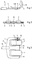
- the knee prosthesis to be used consists of the prosthesis parts 1, 2, the side view of which can be seen from FIG. 1 and the one Sliding surface 3 and a surface 4 to be connected to the bone exhibit. You can also not shown cones or have other surface structures that anchor the in Improve bone and cement adhesion. The example assumes that they agree in the side view and are used exactly parallel to each other. This does not have to be the case be.
- the prosthesis parts 1, 2 are provided with grooves 5 on both edges, that run parallel to each other in the AP direction.
- the Insertion instrument 6 has a double fork 7 with two outer fingers 8 and a middle finger 9, in the spaces between them the prosthesis parts 1, 2 fit. In the front section of the fingers 8, 9 are projecting on their mutually facing side surfaces Last 10 provided the dimensions of the grooves 5 of the prosthesis parts are matched and also parallel to each other.
- the prosthesis parts 1, 2 can therefore each between a pair of fingers 8, 9 with their grooves 5 the strips 10 are pushed on. These form the aforementioned interacting guide rails.
- the two outer fingers 8 each contain a grub screw 11, whose tip, as shown above in Fig. 3, in a corresponding Taper bore 12 of the associated prosthetic part engages and this in the correct insertion position on the insertion device 6 saves.
- the insertion device 6 has a handle 13 on which a not shown handle is provided.
- the longitudinal direction of the stem 13 and the insertion device as a whole agrees with the direction of the Last 10 essentially match.
- the device allows the two prosthesis parts to be put together and in exact mutual alignment and to use them in the hold the intended position until the bone cement attaching it is hardened. Then the grub screws 11 solved and the device can be directed in an anterior direction Movement be taken away. It can be seen from the drawing that it can be made very flat and therefore in the operating field takes up little space.
Abstract
Anordnung zum Einsetzen einer femoralen Knie-Gleitflächen-Endoprothese bestehend aus einem Einsetzgerät (6) sowie zusammenwirkenden Halteeinrichtungen an diesem und der Prothese (1, 2). Das Einsetzgerät (6) bildet zwei Aufnahmen (8, 9) für unverbundene Condylenprothesenteile (1, 2). Jede Aufnahme (8, 9) wirkt mit dem zugehörigen Condylenprothesenteil (1, 2) über mindestens ein Paar von Führungsschienen (5, 10) zusammen, von denen eine Führungsschiene (5) am Seitenrand des Condylenprothesenteils (1 bzw. 2) angeordnet ist. Diese Führungsschienen laufen zweckmäßigerweise etwa in AP-Richtung und sind zweckmäßigerweise beidseitig an den Aufnahmen (8, 9) und Prothesenteilen (1, 2) vorgesehen. Eine Arretierungseinrichtung (11) kann zum Arretieren der Prothesenteile (1, 2) in den Aufnahmen (8, 9) vorgesehen sein. <IMAGE>Arrangement for inserting a femoral knee sliding surface endoprosthesis consisting of an insertion device (6) and interacting holding devices on this and the prosthesis (1, 2). The insertion device (6) forms two receptacles (8, 9) for unconnected condyle prosthesis parts (1, 2). Each receptacle (8, 9) interacts with the associated condyle prosthesis part (1, 2) via at least one pair of guide rails (5, 10), of which a guide rail (5) is arranged on the side edge of the condyle prosthesis part (1 or 2). These guide rails expediently run approximately in the AP direction and are expediently provided on both sides on the receptacles (8, 9) and prosthesis parts (1, 2). A locking device (11) can be provided for locking the prosthesis parts (1, 2) in the receptacles (8, 9). <IMAGE>
Description
Zum Ersatz der femoralen (oberschenkelseitigen) Condylengleitflächen des Kniegelenks sind Gleitflächenprothesen bekannt, die verhältnismäßig dünn ausgeführt sind und daher nur geringe Resektion des Knorpel- und Knochenmaterials verlangen und in manchen Fällen die teilweise oder vollständige Erhaltung der harten Knochenrinde gestatten. In der Regel werden die den beiden Condylen zugeordneten Prothesengleitflächen durch einen schildartigen Teil verbunden, der auf der Vorderseite hochragt und eine Gleitfläche für die Kniescheibe bildet. Eine solche Verbindung der Condylengleitflächen sichert ihre korrekt aufeinander abgestimmte Position. In vielen Fällen ist der Ersatz der Kniescheibengleitfläche nicht erforderlich. Man könnte sich dann mit einer einfacheren Verbindung der beiden Condylengleitflächen begnügen. Jedoch hat die Erfahrung gezeigt, daß eine einfachere Verbindung den Gebrauchsbeanspruchungen oftmals nicht gewachsen ist und bricht. Man kann statt dessen zu unverbundenen Condylengleitflächen greifen, die aber den Nachteil haben, daß ihre korrekte gegenseitige Positionierung freihändig kaum möglich ist. For replacement of the femoral (thigh side) condylar sliding surfaces of the knee joint are known sliding surface prostheses are made relatively thin and therefore only slight resection of cartilage and bone material, and in some Cases the partial or complete preservation of the hard Allow bark. Usually the two of them Condyle-associated prosthesis sliding surfaces by a shield-like Part connected, which protrudes on the front and forms a sliding surface for the patella. Such a connection of the condylar sliding surfaces secures one another correctly coordinated position. In many cases the replacement is the Patella sliding surface not required. You could be then with a simpler connection of the two condylar sliding surfaces content. However, experience has shown that a often easier connection to the stresses of use has not grown and breaks. One can be too disconnected instead Condylar sliding surfaces grip, but the disadvantage have their correct mutual positioning hands-free is hardly possible.
Zum Einsetzen von gegenseitig positionierten Tibiaplateaus ist ein Werkzeug bekannt (Prospekt "Schalen-Kniegelenkprothesen-System SKI" der Firma Interplanta GmbH, Hamburg), das zwei zueinander parallele, je in eine Bohrung eines der Plateaus einschiebbare Stifte und zwei quer dazu verlaufende, jeweils in eine Querbohrung fassende Dornen aufweist. Eine solche Lösung ist bei Condylen-Gleitflächenprothesen nicht anwendbar, vor allem, weil die Lage der Gleitfläche die Unterbringung der genannten Bohrungen nicht gestattet.To insert mutually positioned tibial plateaus a tool known (prospectus "cup-knee prosthesis system SKI "from Interplanta GmbH, Hamburg), the two to each other parallel, each insertable into a hole in one of the plateaus Pens and two transverse to each, in has a transverse bore thorns. Such a solution is not applicable to condyle gliding surface prostheses, especially because the location of the sliding surface accommodates the above Drilling is not permitted.
Der Erfindung liegt daher die Aufgabe zugrunde, eine Anordnung zu schaffen, die das Einsetzen einer femoralen Knie-Gleitflächen-Endoprothese mit korrekt aufeinander abgestimmten Condylengleitflächenteilen ermöglicht.The invention is therefore based on the object of an arrangement to create the insertion of a femoral knee sliding surface endoprosthesis with correctly coordinated condylar sliding surface parts enables.
Die erfindungsgemäße Lösung besteht in den Merkmalen des Anspruchs
1 und vorzugsweise auch denjenigen der Unteransprüche.The solution according to the invention consists in the features of the
Die Erfindung setzt voraus, daß unverbundene Gleitflächenprothesenteile verwendet werden. Deren korrekte gegenseitige Positionierung wird durch entsprechend ausgerichtetete Halterungseinrichtungen in einem Einsetzinstrument gewährleistet, das zwei Aufnahmen für die Prothesenteile bildet. Diese sind mit zu den Halterungsteilen des Einsetzgeräts passenden Halterungselementen ausgerüstet. Diese bestehen aus jeweils einem Schienenpaar, das vorzugsweise etwa in AP-Richtung (Anterior-Posterior-Richtung) angeordnet ist. Das ist die Richtung, die bei gestrecktem Knie von vorne nach hinten verläuft, also in einer Sagittalebene lotrecht zur Richtung des Oberschenkelknochens. Dies Merkmal gestattet es, das Werkzeug mit den jeweils U-förmigen Aufnahmen nach dem Einsetzen der Prothesenteile nach vorne wegzuziehen.The invention requires that unconnected sliding surface prosthesis parts be used. Their correct mutual positioning is carried out by appropriately aligned mounting devices guaranteed in an insertion tool that forms two receptacles for the prosthesis parts. These are with too the bracket parts of the insertion device matching bracket elements equipped. These consist of a pair of rails, preferably in the AP direction (anterior-posterior direction) is arranged. That is the direction when stretched Knee runs from front to back, i.e. in one Sagittal plane perpendicular to the direction of the femur. This feature allows the tool to be U-shaped Images taken after the prosthesis parts are inserted to the front move away.
Die Schienenpaare sind zweckmäßigerweise beidseitig an den Aufnahmen und den Prothesenteilen vorgesehen. Statische Eindeutigkeit ist aber auch dann schon gegeben, wenn lediglich an einer Seite der Aufnahmen und der Prothesenteile ein Schienenpaar angeordnet ist, während auf der anderen Seite eine punktförmige oder sonstwie geartete Halterung vorgesehen ist. Beispielsweise kann am Rand des Prothesenteils eine Bohrung oder Körnereinsenkung vorgesehen sein, in die die Spitze einer an der Aufnahme vorgesehenen Schraube eingreift, die zum Lösen des Geräts von den Prothesenteilen gelöst wird.The pairs of rails are expediently on both sides of the receptacles and the prosthesis parts provided. Static uniqueness is already given, if only on one A pair of rails is arranged on the side of the receptacles and the prosthesis parts is, while on the other hand a punctiform or other type of holder is provided. For example there may be a hole or a depression in the edge of the prosthesis part be provided in the tip of one at the receptacle engages provided screw, which for releasing the device from the prosthesis parts is released.
In jedem Fall, also auch dann, wenn die Schienenanordnungen beidseitig vorgesehen sind, sollte eine Arretierungseinrichtung vorgesehen sein, die dafür sorgt, daß die Prothesenteile ihre korrekte Ausgangsstellung bis zur Beendigung des Einsetzvorgangs beibehalten. Diese Arretierungseinrichtung kann beispielsweise von einer an den Aufnahmen jeweils vorgesehenen Klemmschraube gebildet sein.In any case, even if the rail arrangements are provided on both sides, a locking device be provided, which ensures that the prosthesis parts their correct starting position until the end of the insertion process maintained. This locking device can for example from one provided on the recordings Clamping screw must be formed.
Wenn im vorliegenden Zusammenhang allgemein von Führungsschienen gesprochen wird, so sind damit sämtliche Konfigurationen gemeint, die zwangsläufig eine Ausrichtung der Prothesenteile bewirken und es gestatten, das Gerät nach einer Richtung hin von den implantierten Prothesenteilen abzuziehen. Vorzugsweise ist wenigstens eine Führungsschiene jedes Schienenpaars von einer im wesentlichen durchgehenden Nut oder Leiste gebildet. Bei dem anderen Teil genügt es dann, die Schiene durch eine Mehrzahl von Vorsprüngen anzudeuten. Wenn beispielsweise die Schiene am Rand des Prothesenteils als durchgehende Nut ausgeführt ist, kann man sich an der Aufnahme mit zwei in Abstand voneinander in die Nut eingreifenden Vorsprüngen begnügen. Oder wenn die Schiene an der Aufnahme von einer durchgehenden Leiste gebildet wird, kann man sich am Rand des Prothesenteils mit zwei Stiftpaaren oder zwei in Abstand voneinander auf einer der Leiste angeordneten Stiften und einer etwa mittig dazu auf der anderen Seite der Leiste angeordneten Stift begnügen. Die jeweils andere Schiene braucht auch nicht durchgehend ausgeführt zu sein; sie kann vielmehr an denjenigen Stellen unterbrochen sein, an denen ein Zusammenwirken mit entsprechenden Elementen des anderen Teils nicht erforderlich ist. Die Andeutung einer der beiden Schienen durch vereinzelte Vorsprünge hat auch den Vorteil, daß die erwünschte Ausrichtung der Prothesenteile gegenüber dem Einsetzgerät lediglich dann vorhanden ist, wenn die Prothesenteile korrekt in der Einsetzposition im Gerät fixiert sind. Sie endet sofort, nachdem man begonnen hat, das Gerät von den eingesetzten Implantaten zu entfernen, wodurch die Gefahr verringert wird, daß durch ungeschickte Bewegung beim Entfernen des Geräts die Implantate aus der ihnen zugedachten Position verrückt werden.If in the present context generally of guide rails is spoken, so are all configurations meant the inevitable alignment of the prosthesis parts effect and allow the device to move in one direction to be deducted from the implanted prosthesis parts. Preferably is at least one guide rail of each rail pair of one essentially continuous groove or ledge formed. At the other part, it is then sufficient to use a plurality of rails of hints. If, for example, the rail designed as a continuous groove on the edge of the prosthesis part is, you can look at the recording with two spaced apart protrusions engaging in the groove are sufficient. Or when the rail on the receptacle is formed by a continuous bar can, you can with two at the edge of the prosthesis part Pairs of pins or two spaced apart on one of the bars arranged pins and one about the center of it on the other Satisfy the pin located on the side of the bar. The each other rails do not need to be carried out continuously be; rather, it can be interrupted at those points be in cooperation with corresponding elements the other part is not required. The hint of a of the two rails by isolated projections also has the Advantage that the desired alignment of the prosthesis parts opposite the insertion device is only present when the Prosthesis parts correctly fixed in the insertion position in the device are. It ends immediately after starting the device from remove the implants used, reducing the risk is reduced by clumsy movement when removing the implants from their intended position getting crazy.
In erster Linie ist die erfindungsgemäße Anordnung für solche Prothesen vorgesehen, die mittels Knochenzement verankert werden. Bis zur Erhärtung des Zements werden die Prothesenteile durch das Einsetzgerät der korrekt aufeinander ausgerichteten Stellung gehalten.The arrangement according to the invention is primarily for such Prostheses are provided, which are anchored using bone cement. The prosthesis parts are retained until the cement has hardened through the insertion device of the correctly aligned Position held.
Die Erfindung wird im folgenden näher unter Bezugnahme auf das in der Zeichnung dargestellte Ausführungsbeispiel erläutert. Darin zeigen:
- Fig. 1
- eine Lateralansicht des Geräts mit darin fixierten Prothesenteilen,
- Fig. 2
- einen Frontalschnitt und
- Fig. 3
- eine Draufsicht.
- Fig. 1
- a lateral view of the device with prosthesis parts fixed therein,
- Fig. 2
- a frontal cut and
- Fig. 3
- a top view.
Die einzusetzende Knieprothese besteht aus den Prothesenteilen
1, 2, deren Seitenansicht aus Fig. 1 erkennbar ist und die eine
Gleitfläche 3 und eine mit dem Knochen zu verbindende Fläche 4
aufweisen. Sie können zusätzlich nicht dargestellte Zapfen oder
andere Oberflächenstrukturen aufweisen, die die Verankerung im
Knochen und die Haftung am Zement verbessern. Das Beispiel
setzt voraus, daß sie in der Seitenansicht übereinstimmen und
genau parallel zueinander einzusetzen sind. Dies muß nicht so
sein.The knee prosthesis to be used consists of the
Die Prothesenteile 1, 2 sind an beiden Rändern mit Nuten 5 versehen,
die parallel zueinander in AP-Richtung verlaufen. Das
Einsetzinstrument 6 weist eine Doppelgabel 7 auf mit zwei Außenfingern
8 und einem Mittelfinger 9, in deren Zwischenräume
die Prothesenteile 1, 2 passen. Im vorderen Abschnitt der Finger
8, 9 sind an deren einander zugewendeten Seitenflächen vorspringende
Leisten 10 vorgesehen, deren Abmessungen auf die Nuten
5 der Prothesenteile abgestimmt sind und die ebenfalls parallel
zueinander verlaufen. Die Prothesenteile 1, 2 können daher
jeweils zwischen ein Fingerpaar 8, 9 mit ihren Nuten 5 auf
die Leisten 10 aufgeschoben werden. Diese bilden die zuvor genannten,
zusammenwirkenden Führungsschienen.The
Die beiden Außenfinger 8 enthalten jeweils eine Madenschraube
11, deren Spitze, wie oben in Fig. 3 gezeigt, in eine entsprechende
Konusbohrung 12 des zugehörigen Prothesenteils eingreift
und dieses dadurch in der korrekten Einsetzlage am Einsetzgerät
6 sichert.The two
Das Einsetzgerät 6 weist einen Stiel 13 auf, an dem ein nicht
gezeigter Griff vorgesehen ist. Die Längsrichtung des Stiels 13
und des Einsetzgeräts insgesamt stimmt mit der Richtung der
Leisten 10 im wesentlichen überein.The
Das Gerät gestattet es, die beiden Prothesenteile gemeinsam und
in genauer gegenseitiger Ausrichtung einzusetzen und sie in der
vorgesehenen Position zu halten, bis der sie befestigende Knochenzement
erhärtet ist. Danach werden die Madenschrauben 11
gelöst und das Gerät kann in einer nach anterior gerichteten
Bewegung weggenommen werden. Man sieht aus der Zeichnung, daß
es sehr flach ausgeführt sein kann und daher im Operationsfeld
nur geringen Platz einnimmt.The device allows the two prosthesis parts to be put together and
in exact mutual alignment and to use them in the
hold the intended position until the bone cement attaching it
is hardened. Then the
Claims (4)
Applications Claiming Priority (2)
| Application Number | Priority Date | Filing Date | Title |
|---|---|---|---|
| DE29614349U DE29614349U1 (en) | 1996-08-19 | 1996-08-19 | Arrangement for inserting a femoral knee-sliding surface endoprosthesis |
| DE29614349U | 1996-08-19 |
Publications (2)
| Publication Number | Publication Date |
|---|---|
| EP0824904A2 true EP0824904A2 (en) | 1998-02-25 |
| EP0824904A3 EP0824904A3 (en) | 1998-11-18 |
Family
ID=8028024
Family Applications (1)
| Application Number | Title | Priority Date | Filing Date |
|---|---|---|---|
| EP97112565A Withdrawn EP0824904A3 (en) | 1996-08-19 | 1997-07-22 | Device for implanting the femoral articular element of a knee endoprosthesis |
Country Status (4)
| Country | Link |
|---|---|
| US (1) | US5902339A (en) |
| EP (1) | EP0824904A3 (en) |
| JP (1) | JP3662721B2 (en) |
| DE (1) | DE29614349U1 (en) |
Cited By (5)
| Publication number | Priority date | Publication date | Assignee | Title |
|---|---|---|---|---|
| EP1099430A1 (en) | 1999-11-09 | 2001-05-16 | Waldemar Link (GmbH & Co.) | Knee prosthesis system |
| US6482209B1 (en) | 2001-06-14 | 2002-11-19 | Gerard A. Engh | Apparatus and method for sculpting the surface of a joint |
| US6723102B2 (en) | 2001-06-14 | 2004-04-20 | Alexandria Research Technologies, Llc | Apparatus and method for minimally invasive total joint replacement |
| US8002840B2 (en) | 2004-01-12 | 2011-08-23 | Depuy Products, Inc. | Systems and methods for compartmental replacement in a knee |
| US8535383B2 (en) | 2004-01-12 | 2013-09-17 | DePuy Synthes Products, LLC | Systems and methods for compartmental replacement in a knee |
Families Citing this family (14)
| Publication number | Priority date | Publication date | Assignee | Title |
|---|---|---|---|---|
| US6478799B1 (en) * | 2000-06-29 | 2002-11-12 | Richard V. Williamson | Instruments and methods for use in performing knee surgery |
| US20070173858A1 (en) * | 2001-06-14 | 2007-07-26 | Alexandria Research Technologies, Llc | Apparatus and Method for Sculpting the Surface of a Joint |
| US7153310B2 (en) * | 2001-07-16 | 2006-12-26 | Spinecore, Inc. | Vertebral bone distraction instruments |
| TR200402563T4 (en) * | 2001-12-10 | 2004-12-21 | Waldemar Link Gmbh & Co. Kg | Fitting tool for sliding dentures. |
| EP2359775B1 (en) * | 2002-02-20 | 2012-12-26 | Zimmer, Inc. | Knee arthroplasty prosthesis |
| US7235106B2 (en) * | 2002-12-20 | 2007-06-26 | Depuy Products, Inc. | Modular hip stems and associated method of trialing |
| US7022141B2 (en) * | 2002-12-20 | 2006-04-04 | Depuy Products, Inc. | Alignment device for modular implants and method |
| US7854737B2 (en) * | 2002-12-20 | 2010-12-21 | Depuy Products, Inc. | Instrument and associated method of trailing for modular hip stems |
| DE50301622D1 (en) * | 2003-08-07 | 2005-12-15 | Link Waldemar Gmbh Co | Insertion tool for a pair of sled prostheses |
| EP1703867B1 (en) * | 2004-01-12 | 2012-03-07 | Depuy Products, Inc. | Systems for compartmental replacement in a knee |
| US7632284B2 (en) * | 2004-07-06 | 2009-12-15 | Tyco Healthcare Group Lp | Instrument kit and method for performing meniscal repair |
| JP5252968B2 (en) * | 2007-07-30 | 2013-07-31 | 京セラメディカル株式会社 | Femoral component retention device |
| GB0911643D0 (en) * | 2009-07-04 | 2009-08-12 | Depuy Ireland | Surgical instrument |
| US10092421B2 (en) | 2012-09-28 | 2018-10-09 | Depuy Ireland Unlimited Company | Surgical instrument and method of use |
Citations (3)
| Publication number | Priority date | Publication date | Assignee | Title |
|---|---|---|---|---|
| FR2266492A1 (en) * | 1974-04-08 | 1975-10-31 | Garonne Ets Auriol & Cie | Artificial knee joint - has plates removable from tibia base sections and supporting femoral assembly |
| US3949428A (en) * | 1973-09-07 | 1976-04-13 | National Research Development Corporation | Prosthetic bone joint devices |
| US5059196A (en) * | 1991-03-07 | 1991-10-22 | Dow Corning Wright Corporation | Femoral prosthesis holder/driver tool and method of implantation using same |
Family Cites Families (7)
| Publication number | Priority date | Publication date | Assignee | Title |
|---|---|---|---|---|
| US3715763A (en) * | 1971-04-21 | 1973-02-13 | W Link | Artificial limb for the knee joint |
| CA1045752A (en) * | 1975-05-26 | 1979-01-09 | Robert W. Jackson | Prosthetic implant |
| US4211228A (en) * | 1979-01-24 | 1980-07-08 | Cloutier Jean Marie | Multipurpose tibial template |
| US5520695A (en) * | 1992-02-14 | 1996-05-28 | Johnson & Johnson Professional, Inc. | Instruments for use in knee replacement surgery |
| FR2691355A1 (en) * | 1992-05-19 | 1993-11-26 | Deux C T | Two-part replacement prosthesis for knee joint tibial surface - has base implanted into upper surface of tibia by downwardly-projecting fasteners, with peripheral groove engaged by separate rubbing block |
| SE9201671D0 (en) * | 1992-05-27 | 1992-05-27 | Astra Ab | KNEE JOINT PROSTHESIS III F |
| DE69317283T2 (en) * | 1992-06-17 | 1998-09-24 | Minnesota Mining & Mfg | INSTRUMENTS FOR PREPARING THE FEMUR FOR AN ARTIFICIAL KNEE IMPLANT AND FOR POSITIONING THE FEMORAL IMPLANT |
-
1996
- 1996-08-19 DE DE29614349U patent/DE29614349U1/en not_active Expired - Lifetime
-
1997
- 1997-07-22 EP EP97112565A patent/EP0824904A3/en not_active Withdrawn
- 1997-08-19 JP JP22249597A patent/JP3662721B2/en not_active Expired - Fee Related
- 1997-08-19 US US08/914,710 patent/US5902339A/en not_active Expired - Lifetime
Patent Citations (3)
| Publication number | Priority date | Publication date | Assignee | Title |
|---|---|---|---|---|
| US3949428A (en) * | 1973-09-07 | 1976-04-13 | National Research Development Corporation | Prosthetic bone joint devices |
| FR2266492A1 (en) * | 1974-04-08 | 1975-10-31 | Garonne Ets Auriol & Cie | Artificial knee joint - has plates removable from tibia base sections and supporting femoral assembly |
| US5059196A (en) * | 1991-03-07 | 1991-10-22 | Dow Corning Wright Corporation | Femoral prosthesis holder/driver tool and method of implantation using same |
Cited By (8)
| Publication number | Priority date | Publication date | Assignee | Title |
|---|---|---|---|---|
| EP1099430A1 (en) | 1999-11-09 | 2001-05-16 | Waldemar Link (GmbH & Co.) | Knee prosthesis system |
| WO2001034069A1 (en) * | 1999-11-09 | 2001-05-17 | Waldemar Link (Gmbh & Co.) | Knee prosthesis system |
| US6743258B1 (en) | 1999-11-09 | 2004-06-01 | Waldemar Link (Gmbh & Co.) | Knee prosthesis system |
| US6482209B1 (en) | 2001-06-14 | 2002-11-19 | Gerard A. Engh | Apparatus and method for sculpting the surface of a joint |
| US6723102B2 (en) | 2001-06-14 | 2004-04-20 | Alexandria Research Technologies, Llc | Apparatus and method for minimally invasive total joint replacement |
| US7896922B2 (en) | 2001-06-14 | 2011-03-01 | Alexandria Research Technologies, Llc | Implants for partial knee arthroplasty |
| US8002840B2 (en) | 2004-01-12 | 2011-08-23 | Depuy Products, Inc. | Systems and methods for compartmental replacement in a knee |
| US8535383B2 (en) | 2004-01-12 | 2013-09-17 | DePuy Synthes Products, LLC | Systems and methods for compartmental replacement in a knee |
Also Published As
| Publication number | Publication date |
|---|---|
| JP3662721B2 (en) | 2005-06-22 |
| US5902339A (en) | 1999-05-11 |
| EP0824904A3 (en) | 1998-11-18 |
| DE29614349U1 (en) | 1997-12-18 |
| JPH1075972A (en) | 1998-03-24 |
Similar Documents
| Publication | Publication Date | Title |
|---|---|---|
| EP0824904A2 (en) | Device for implanting the femoral articular element of a knee endoprosthesis | |
| EP1099430B1 (en) | Knee prosthesis system | |
| EP1658023B1 (en) | Ankle-joint endoprosthesis | |
| EP0855173B1 (en) | Fastening of a ceramic element as a friction component of a tibial piece | |
| EP1504733B1 (en) | Cervical prosthesis with insertion instrument | |
| EP0928172B1 (en) | Shankless knee joint endoprosthesis | |
| EP0145641B1 (en) | Modular resection prosthesis assembly | |
| EP1482874B1 (en) | Ankle-joint endoprosthesis | |
| DE602005003462T2 (en) | ASSEMBLY ARRANGEMENT FOR IMPLANTING KNEE PROSTHESES | |
| DE2442927C2 (en) | Knee joint endoprosthesis and device for its alignment | |
| WO2002009596A1 (en) | Device for aligning a guide template | |
| EP1729673A2 (en) | Cervical intervertebral prosthesis | |
| DE3205577C2 (en) | Endoprosthesis for femoral or tibial articular bone parts and adjacent femoral or tibial bone sections | |
| DE3013155A1 (en) | TIBIA PROSTHESIS | |
| DE2320683A1 (en) | ENDOPROSTHESIS FOR THE PROXIMAL HIP PART | |
| DE3010421A1 (en) | INSTRUMENT FOR HOLDING AND INSERTING THE TIBIA PLATE FOR A KNEE-JOINT SLIDING PROSTHESIS | |
| EP1470786A1 (en) | Device for preparation of a femoral condyle | |
| DE10309500A1 (en) | Patella reference device | |
| EP0158014A1 (en) | Hip prosthesis | |
| EP0680292A1 (en) | System for constructing a knee-joint endoprosthesis | |
| DE2901009A1 (en) | Internal artificial knee joint - has insert piece joined to dish by guide ensuring smooth sliding movement | |
| EP1321116A1 (en) | Insertion instrument for femoral sled prosthesis | |
| DE202004015198U1 (en) | Intervertebral implant system, includes facette joint implant with two parts for cooperating with adjacent vertebrae bodies | |
| DE2114287B2 (en) | JOINT PROSTHESIS FOR THE REPLACEMENT OF BONE TISSUE IN THE AREA OF A HUMAN KNEE | |
| EP0177755B1 (en) | Tibial-prosthetic part of a knee joint endoprosthesis |
Legal Events
| Date | Code | Title | Description |
|---|---|---|---|
| PUAI | Public reference made under article 153(3) epc to a published international application that has entered the european phase |
Free format text: ORIGINAL CODE: 0009012 |
|
| AK | Designated contracting states |
Kind code of ref document: A2 Designated state(s): DE ES FR GB IT |
|
| PUAL | Search report despatched |
Free format text: ORIGINAL CODE: 0009013 |
|
| AK | Designated contracting states |
Kind code of ref document: A3 Designated state(s): AT BE CH DE DK ES FI FR GB GR IE IT LI LU MC NL PT SE |
|
| 17P | Request for examination filed |
Effective date: 19981222 |
|
| AKX | Designation fees paid |
Free format text: DE ES FR GB IT |
|
| 17Q | First examination report despatched |
Effective date: 20010525 |
|
| STAA | Information on the status of an ep patent application or granted ep patent |
Free format text: STATUS: THE APPLICATION IS DEEMED TO BE WITHDRAWN |
|
| 18D | Application deemed to be withdrawn |
Effective date: 20011005 |