EP0824893A2 - Apparatus for osteochondral autograft transplantation - Google Patents
Apparatus for osteochondral autograft transplantation Download PDFInfo
- Publication number
- EP0824893A2 EP0824893A2 EP97306035A EP97306035A EP0824893A2 EP 0824893 A2 EP0824893 A2 EP 0824893A2 EP 97306035 A EP97306035 A EP 97306035A EP 97306035 A EP97306035 A EP 97306035A EP 0824893 A2 EP0824893 A2 EP 0824893A2
- Authority
- EP
- European Patent Office
- Prior art keywords
- harvester
- core
- tube
- donor
- recipient
- Prior art date
- Legal status (The legal status is an assumption and is not a legal conclusion. Google has not performed a legal analysis and makes no representation as to the accuracy of the status listed.)
- Granted
Links
Images


Classifications
-
- A—HUMAN NECESSITIES
- A61—MEDICAL OR VETERINARY SCIENCE; HYGIENE
- A61B—DIAGNOSIS; SURGERY; IDENTIFICATION
- A61B10/00—Other methods or instruments for diagnosis, e.g. instruments for taking a cell sample, for biopsy, for vaccination diagnosis; Sex determination; Ovulation-period determination; Throat striking implements
- A61B10/02—Instruments for taking cell samples or for biopsy
- A61B10/0233—Pointed or sharp biopsy instruments
- A61B10/025—Pointed or sharp biopsy instruments for taking bone, bone marrow or cartilage samples
-
- A—HUMAN NECESSITIES
- A61—MEDICAL OR VETERINARY SCIENCE; HYGIENE
- A61B—DIAGNOSIS; SURGERY; IDENTIFICATION
- A61B17/00—Surgical instruments, devices or methods, e.g. tourniquets
- A61B17/16—Bone cutting, breaking or removal means other than saws, e.g. Osteoclasts; Drills or chisels for bones; Trepans
- A61B17/1635—Bone cutting, breaking or removal means other than saws, e.g. Osteoclasts; Drills or chisels for bones; Trepans for grafts, harvesting or transplants
-
- A—HUMAN NECESSITIES
- A61—MEDICAL OR VETERINARY SCIENCE; HYGIENE
- A61B—DIAGNOSIS; SURGERY; IDENTIFICATION
- A61B17/00—Surgical instruments, devices or methods, e.g. tourniquets
- A61B17/16—Bone cutting, breaking or removal means other than saws, e.g. Osteoclasts; Drills or chisels for bones; Trepans
- A61B17/1637—Hollow drills or saws producing a curved cut, e.g. cylindrical
-
- A—HUMAN NECESSITIES
- A61—MEDICAL OR VETERINARY SCIENCE; HYGIENE
- A61B—DIAGNOSIS; SURGERY; IDENTIFICATION
- A61B17/00—Surgical instruments, devices or methods, e.g. tourniquets
- A61B17/16—Bone cutting, breaking or removal means other than saws, e.g. Osteoclasts; Drills or chisels for bones; Trepans
- A61B17/1662—Bone cutting, breaking or removal means other than saws, e.g. Osteoclasts; Drills or chisels for bones; Trepans for particular parts of the body
- A61B17/1675—Bone cutting, breaking or removal means other than saws, e.g. Osteoclasts; Drills or chisels for bones; Trepans for particular parts of the body for the knee
-
- A—HUMAN NECESSITIES
- A61—MEDICAL OR VETERINARY SCIENCE; HYGIENE
- A61B—DIAGNOSIS; SURGERY; IDENTIFICATION
- A61B17/00—Surgical instruments, devices or methods, e.g. tourniquets
- A61B17/16—Bone cutting, breaking or removal means other than saws, e.g. Osteoclasts; Drills or chisels for bones; Trepans
- A61B17/17—Guides or aligning means for drills, mills, pins or wires
- A61B17/1714—Guides or aligning means for drills, mills, pins or wires for applying tendons or ligaments
-
- A—HUMAN NECESSITIES
- A61—MEDICAL OR VETERINARY SCIENCE; HYGIENE
- A61B—DIAGNOSIS; SURGERY; IDENTIFICATION
- A61B17/00—Surgical instruments, devices or methods, e.g. tourniquets
- A61B17/56—Surgical instruments or methods for treatment of bones or joints; Devices specially adapted therefor
- A61B17/58—Surgical instruments or methods for treatment of bones or joints; Devices specially adapted therefor for osteosynthesis, e.g. bone plates, screws, setting implements or the like
- A61B17/68—Internal fixation devices, including fasteners and spinal fixators, even if a part thereof projects from the skin
- A61B17/84—Fasteners therefor or fasteners being internal fixation devices
- A61B17/86—Pins or screws or threaded wires; nuts therefor
- A61B17/8605—Heads, i.e. proximal ends projecting from bone
-
- A—HUMAN NECESSITIES
- A61—MEDICAL OR VETERINARY SCIENCE; HYGIENE
- A61F—FILTERS IMPLANTABLE INTO BLOOD VESSELS; PROSTHESES; DEVICES PROVIDING PATENCY TO, OR PREVENTING COLLAPSING OF, TUBULAR STRUCTURES OF THE BODY, e.g. STENTS; ORTHOPAEDIC, NURSING OR CONTRACEPTIVE DEVICES; FOMENTATION; TREATMENT OR PROTECTION OF EYES OR EARS; BANDAGES, DRESSINGS OR ABSORBENT PADS; FIRST-AID KITS
- A61F2/00—Filters implantable into blood vessels; Prostheses, i.e. artificial substitutes or replacements for parts of the body; Appliances for connecting them with the body; Devices providing patency to, or preventing collapsing of, tubular structures of the body, e.g. stents
- A61F2/02—Prostheses implantable into the body
- A61F2/30—Joints
- A61F2/46—Special tools or methods for implanting or extracting artificial joints, accessories, bone grafts or substitutes, or particular adaptations therefor
- A61F2/4601—Special tools or methods for implanting or extracting artificial joints, accessories, bone grafts or substitutes, or particular adaptations therefor for introducing bone substitute, for implanting bone graft implants or for compacting them in the bone cavity
-
- A—HUMAN NECESSITIES
- A61—MEDICAL OR VETERINARY SCIENCE; HYGIENE
- A61F—FILTERS IMPLANTABLE INTO BLOOD VESSELS; PROSTHESES; DEVICES PROVIDING PATENCY TO, OR PREVENTING COLLAPSING OF, TUBULAR STRUCTURES OF THE BODY, e.g. STENTS; ORTHOPAEDIC, NURSING OR CONTRACEPTIVE DEVICES; FOMENTATION; TREATMENT OR PROTECTION OF EYES OR EARS; BANDAGES, DRESSINGS OR ABSORBENT PADS; FIRST-AID KITS
- A61F2/00—Filters implantable into blood vessels; Prostheses, i.e. artificial substitutes or replacements for parts of the body; Appliances for connecting them with the body; Devices providing patency to, or preventing collapsing of, tubular structures of the body, e.g. stents
- A61F2/02—Prostheses implantable into the body
- A61F2/30—Joints
- A61F2/46—Special tools or methods for implanting or extracting artificial joints, accessories, bone grafts or substitutes, or particular adaptations therefor
- A61F2/4603—Special tools or methods for implanting or extracting artificial joints, accessories, bone grafts or substitutes, or particular adaptations therefor for insertion or extraction of endoprosthetic joints or of accessories thereof
- A61F2/4618—Special tools or methods for implanting or extracting artificial joints, accessories, bone grafts or substitutes, or particular adaptations therefor for insertion or extraction of endoprosthetic joints or of accessories thereof of cartilage
-
- A—HUMAN NECESSITIES
- A61—MEDICAL OR VETERINARY SCIENCE; HYGIENE
- A61F—FILTERS IMPLANTABLE INTO BLOOD VESSELS; PROSTHESES; DEVICES PROVIDING PATENCY TO, OR PREVENTING COLLAPSING OF, TUBULAR STRUCTURES OF THE BODY, e.g. STENTS; ORTHOPAEDIC, NURSING OR CONTRACEPTIVE DEVICES; FOMENTATION; TREATMENT OR PROTECTION OF EYES OR EARS; BANDAGES, DRESSINGS OR ABSORBENT PADS; FIRST-AID KITS
- A61F2/00—Filters implantable into blood vessels; Prostheses, i.e. artificial substitutes or replacements for parts of the body; Appliances for connecting them with the body; Devices providing patency to, or preventing collapsing of, tubular structures of the body, e.g. stents
- A61F2/02—Prostheses implantable into the body
- A61F2/30—Joints
- A61F2/46—Special tools or methods for implanting or extracting artificial joints, accessories, bone grafts or substitutes, or particular adaptations therefor
- A61F2/4657—Measuring instruments used for implanting artificial joints
-
- A—HUMAN NECESSITIES
- A61—MEDICAL OR VETERINARY SCIENCE; HYGIENE
- A61B—DIAGNOSIS; SURGERY; IDENTIFICATION
- A61B17/00—Surgical instruments, devices or methods, e.g. tourniquets
- A61B17/16—Bone cutting, breaking or removal means other than saws, e.g. Osteoclasts; Drills or chisels for bones; Trepans
- A61B17/1604—Chisels; Rongeurs; Punches; Stamps
-
- A—HUMAN NECESSITIES
- A61—MEDICAL OR VETERINARY SCIENCE; HYGIENE
- A61B—DIAGNOSIS; SURGERY; IDENTIFICATION
- A61B17/00—Surgical instruments, devices or methods, e.g. tourniquets
- A61B2017/0046—Surgical instruments, devices or methods, e.g. tourniquets with a releasable handle; with handle and operating part separable
-
- A—HUMAN NECESSITIES
- A61—MEDICAL OR VETERINARY SCIENCE; HYGIENE
- A61B—DIAGNOSIS; SURGERY; IDENTIFICATION
- A61B90/00—Instruments, implements or accessories specially adapted for surgery or diagnosis and not covered by any of the groups A61B1/00 - A61B50/00, e.g. for luxation treatment or for protecting wound edges
- A61B90/06—Measuring instruments not otherwise provided for
- A61B2090/062—Measuring instruments not otherwise provided for penetration depth
-
- A—HUMAN NECESSITIES
- A61—MEDICAL OR VETERINARY SCIENCE; HYGIENE
- A61F—FILTERS IMPLANTABLE INTO BLOOD VESSELS; PROSTHESES; DEVICES PROVIDING PATENCY TO, OR PREVENTING COLLAPSING OF, TUBULAR STRUCTURES OF THE BODY, e.g. STENTS; ORTHOPAEDIC, NURSING OR CONTRACEPTIVE DEVICES; FOMENTATION; TREATMENT OR PROTECTION OF EYES OR EARS; BANDAGES, DRESSINGS OR ABSORBENT PADS; FIRST-AID KITS
- A61F2/00—Filters implantable into blood vessels; Prostheses, i.e. artificial substitutes or replacements for parts of the body; Appliances for connecting them with the body; Devices providing patency to, or preventing collapsing of, tubular structures of the body, e.g. stents
- A61F2/02—Prostheses implantable into the body
- A61F2/30—Joints
- A61F2/30756—Cartilage endoprostheses
-
- A—HUMAN NECESSITIES
- A61—MEDICAL OR VETERINARY SCIENCE; HYGIENE
- A61F—FILTERS IMPLANTABLE INTO BLOOD VESSELS; PROSTHESES; DEVICES PROVIDING PATENCY TO, OR PREVENTING COLLAPSING OF, TUBULAR STRUCTURES OF THE BODY, e.g. STENTS; ORTHOPAEDIC, NURSING OR CONTRACEPTIVE DEVICES; FOMENTATION; TREATMENT OR PROTECTION OF EYES OR EARS; BANDAGES, DRESSINGS OR ABSORBENT PADS; FIRST-AID KITS
- A61F2/00—Filters implantable into blood vessels; Prostheses, i.e. artificial substitutes or replacements for parts of the body; Appliances for connecting them with the body; Devices providing patency to, or preventing collapsing of, tubular structures of the body, e.g. stents
- A61F2/02—Prostheses implantable into the body
- A61F2/30—Joints
- A61F2/38—Joints for elbows or knees
- A61F2/3859—Femoral components
-
- A—HUMAN NECESSITIES
- A61—MEDICAL OR VETERINARY SCIENCE; HYGIENE
- A61F—FILTERS IMPLANTABLE INTO BLOOD VESSELS; PROSTHESES; DEVICES PROVIDING PATENCY TO, OR PREVENTING COLLAPSING OF, TUBULAR STRUCTURES OF THE BODY, e.g. STENTS; ORTHOPAEDIC, NURSING OR CONTRACEPTIVE DEVICES; FOMENTATION; TREATMENT OR PROTECTION OF EYES OR EARS; BANDAGES, DRESSINGS OR ABSORBENT PADS; FIRST-AID KITS
- A61F2/00—Filters implantable into blood vessels; Prostheses, i.e. artificial substitutes or replacements for parts of the body; Appliances for connecting them with the body; Devices providing patency to, or preventing collapsing of, tubular structures of the body, e.g. stents
- A61F2/02—Prostheses implantable into the body
- A61F2/30—Joints
- A61F2/30756—Cartilage endoprostheses
- A61F2002/30764—Cartilage harvest sites
-
- A—HUMAN NECESSITIES
- A61—MEDICAL OR VETERINARY SCIENCE; HYGIENE
- A61F—FILTERS IMPLANTABLE INTO BLOOD VESSELS; PROSTHESES; DEVICES PROVIDING PATENCY TO, OR PREVENTING COLLAPSING OF, TUBULAR STRUCTURES OF THE BODY, e.g. STENTS; ORTHOPAEDIC, NURSING OR CONTRACEPTIVE DEVICES; FOMENTATION; TREATMENT OR PROTECTION OF EYES OR EARS; BANDAGES, DRESSINGS OR ABSORBENT PADS; FIRST-AID KITS
- A61F2/00—Filters implantable into blood vessels; Prostheses, i.e. artificial substitutes or replacements for parts of the body; Appliances for connecting them with the body; Devices providing patency to, or preventing collapsing of, tubular structures of the body, e.g. stents
- A61F2/02—Prostheses implantable into the body
- A61F2/30—Joints
- A61F2/46—Special tools or methods for implanting or extracting artificial joints, accessories, bone grafts or substitutes, or particular adaptations therefor
- A61F2/4603—Special tools or methods for implanting or extracting artificial joints, accessories, bone grafts or substitutes, or particular adaptations therefor for insertion or extraction of endoprosthetic joints or of accessories thereof
- A61F2002/4625—Special tools or methods for implanting or extracting artificial joints, accessories, bone grafts or substitutes, or particular adaptations therefor for insertion or extraction of endoprosthetic joints or of accessories thereof with relative movement between parts of the instrument during use
- A61F2002/4627—Special tools or methods for implanting or extracting artificial joints, accessories, bone grafts or substitutes, or particular adaptations therefor for insertion or extraction of endoprosthetic joints or of accessories thereof with relative movement between parts of the instrument during use with linear motion along or rotating motion about the instrument axis or the implantation direction, e.g. telescopic, along a guiding rod, screwing inside the instrument
-
- A—HUMAN NECESSITIES
- A61—MEDICAL OR VETERINARY SCIENCE; HYGIENE
- A61F—FILTERS IMPLANTABLE INTO BLOOD VESSELS; PROSTHESES; DEVICES PROVIDING PATENCY TO, OR PREVENTING COLLAPSING OF, TUBULAR STRUCTURES OF THE BODY, e.g. STENTS; ORTHOPAEDIC, NURSING OR CONTRACEPTIVE DEVICES; FOMENTATION; TREATMENT OR PROTECTION OF EYES OR EARS; BANDAGES, DRESSINGS OR ABSORBENT PADS; FIRST-AID KITS
- A61F2/00—Filters implantable into blood vessels; Prostheses, i.e. artificial substitutes or replacements for parts of the body; Appliances for connecting them with the body; Devices providing patency to, or preventing collapsing of, tubular structures of the body, e.g. stents
- A61F2/02—Prostheses implantable into the body
- A61F2/30—Joints
- A61F2/46—Special tools or methods for implanting or extracting artificial joints, accessories, bone grafts or substitutes, or particular adaptations therefor
- A61F2/4644—Preparation of bone graft, bone plugs or bone dowels, e.g. grinding or milling bone material
- A61F2002/4649—Bone graft or bone dowel harvest sites
-
- A—HUMAN NECESSITIES
- A61—MEDICAL OR VETERINARY SCIENCE; HYGIENE
- A61F—FILTERS IMPLANTABLE INTO BLOOD VESSELS; PROSTHESES; DEVICES PROVIDING PATENCY TO, OR PREVENTING COLLAPSING OF, TUBULAR STRUCTURES OF THE BODY, e.g. STENTS; ORTHOPAEDIC, NURSING OR CONTRACEPTIVE DEVICES; FOMENTATION; TREATMENT OR PROTECTION OF EYES OR EARS; BANDAGES, DRESSINGS OR ABSORBENT PADS; FIRST-AID KITS
- A61F2/00—Filters implantable into blood vessels; Prostheses, i.e. artificial substitutes or replacements for parts of the body; Appliances for connecting them with the body; Devices providing patency to, or preventing collapsing of, tubular structures of the body, e.g. stents
- A61F2/02—Prostheses implantable into the body
- A61F2/30—Joints
- A61F2/46—Special tools or methods for implanting or extracting artificial joints, accessories, bone grafts or substitutes, or particular adaptations therefor
- A61F2/4657—Measuring instruments used for implanting artificial joints
- A61F2002/4662—Measuring instruments used for implanting artificial joints for measuring penetration depth
Definitions
- the present invention relates to the surgical treatment of chondral defects and, more specifically, to
- Chronic ACL deficiency can result in a wide range of chondral damage, varying from superficial blemishes and fissures, to large, full-thickness defects. These lesions may also occur as isolated pathology in cruciate normal knees.
- a protocol of arthroscopic osteochondral autograft transplantation for repairing chondral defects has been developed and tested in knees having chronic ACL deficiency by Vladimir Bobic, as reported in Arthroscopic Osteochondral Autograft Transplantation In ACL Reconstruction: A preliminary clinical study; Knee Surgery, Sports Traumatology Arthroscopy (1996), incorporated herein by reference.
- the transplantation procedure which is intended to prevent further joint degeneration and possible development of osteoarthrosis, involves selecting donor sites for osteochondral cores, capped with intact cartilage, prior to notchplasty. Donor sites are selected along the anterolateral and superior aspect of the notchplasty area, or on the superolateral and anterolateral aspect of the lateral femoral condyle in the non-weightbearing area above the sulcus terminalis. At the donor sites, multiple osteochondral cores 5 mm to 9 mm in diameter and 10 to 15 mm long, are harvested using tubular cutting instruments.
- Recipient repair sites typically are located on the weightbearing area of the medial and lateral femoral condyles. Full-thickness chondral defects, typically larger than 10 mm in diameter, and up to 20 mm, are selected for treatment. Recipient sockets at the repair sites are prepared, and the donor cores are transferred and press-fitted into the recipient sockets.
- the transplantation procedure described above has various difficulties associated with it. For example, removing the osteochondral cores from the tubular cutting instruments is difficult. In addition, improvements are needed in the formation of the donor cores and recipient sockets, especially to facilitate depth control during harvest as well as transplant insertion. In general, improvements are required in the instrumentation and techniques available to perform the transfer procedure.
- the present invention overcomes the deficiencies in the prior art by providing surgical instruments for performing osteochondral transplant procedures using a series of thin-walled (0.5 mm) cutting tubes.
- Osteochondral cores made up of hyaline cartilage capping subchondral bone, are harvested, preferably autogenously.
- the osteochondral cores preferably 10 to 15 mm in length, are transplanted into sockets created in the defect to accept the transplanted core, or multiple cores, in a press-fit manner.
- the technique may be carried out as either an open procedure or arthroscopically. Determinations regarding the protocol used will be based, for example, on the location, geometry, and extent of the chondral defect and the harvest sites.
- the instrumentation of the present invention includes a series of core harvesters.
- the harvester of the present invention preferably includes a hollow tube having a distal cutting edge and a cannulated handle attached proximally.
- a collared pin is disposed slidably to facilitate removal of the harvested osteochondral core.
- the collared pin acts as a plunger to urge the harvested core from the lumen of the core harvester tube, and preferably has a concave face for enhanced biomechanical contact with the curved surface of the harvested core.
- a donor harvester for obtaining donor osteochondral cores
- a recipient site harvester for forming recipient sockets at repair sites.
- the inner diameter of the donor harvester is equal to the outer diameter of the recipient site harvester.
- the outer diameters differ by 1 mm to accommodate the 0.5 mm wall thickness. The thin walls minimize bone and tissue damage.
- the harvesters are provided in a range of sizes.
- markings are provided on the instruments.
- the markings preferably are located on the outer surface of the harvester tubes for direct visual alignment with the surface of the tissue being harvested.
- Slotted windows are provided through the side walls of the tube to allow visualization of the harvested osteochondral core within the lumen of the harvester tube, allowing for visual confirmation of core length and surface geometry, for example, and for visual confirmation of depth during insertion.
- the two types of bone harvesters can be distinguished by the formation of the sharp, distal cutting edge.
- the distal cutting edge preferably is formed as an inward bevel, such that the cutting edge is formed by a slanted surface that slopes distally and inward, toward the central axis, from the outer surface to the inner surface of the harvester tube wall. Accordingly, the acutely-angled cutting edge is formed at the junction between the outer, beveled surface and the inner surface of the harvester tube wall.
- the distal cutting edge preferably is formed with a bevel opposite to that of the donor graft harvester. That is, the cutting edge is formed by a slanted surface that slopes distally and outward from the central axis, from the inner surface to the outer surface of the harvester tube wall. Accordingly, the acutely-angled cutting edge is formed between the inner, beveled surface and the outer surface of the harvester tube wall.
- the two harvesters cooperate for precise correspondence in size between the donor graft and the recipient site. Correct sizing avoids problems associated with an improper fit of the graft in the recipient site, including compression or insufficiency of the repair.
- the donor harvester is inserted into a tube harvester driver/extractor and placed over the selected hyaline cartilage harvest site.
- the donor harvester is placed flush with the articular cartilage surface and impacted, using a mallet for example, to a selected depth of approximately 10 to 15 mm.
- the driver/extractor is twisted and gently rocked to fracture the cancellous base for removal of the osteochondral core.
- a recipient site is prepared with a recipient site harvester using a similar method.
- recipient sockets can be formed using various techniques, such as by drilling.
- the donor core preferably is pressed into the recipient site directly from the donor harvester.
- size correlation between the donor core and the recipient site is provided by using a graft sizer and an alignment stick.
- the depth of the recipient site is determined using the alignment stick. If the graft osteochondral core is too long, adjustment of the core length or the length of the recipient site can be effected accordingly.
- the donor osteochondral core is advanced with the collared pin so that the distal end of the core is flush with the end of the cutting edge of the harvester tube.
- the collared pin is sized so that the proximal end comes flush with the proximal end of the harvester handle when the distal end of the collared pin is 1 mm recessed from the cutting edge of the cutting end of the bone harvester. Accordingly, nearly-flush, anatomical insertion of the cartilage/bone core can be obtained without direct visual observation, and over-insertion is avoided.
- the osteochondral core insert is brought flush anatomically using a sizer/tamp.
- the graft is pressed with the sizer/tamp such that the surface of the graft comes into flush alignment with the normal articular cartilage surrounding the recipient repair site.
- osteochondritis dissecans treatments for the invention can be extended to include other treatments, such as, for example, osteochondritis dissecans, allograft transplantation, bone grafting, graft fixation, and focused bone core biopsy.
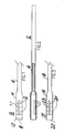
- Fig. 1 is a partial side view of a donor graft harvester according to the present invention.
- Fig. 2 is a cut-away side view of the donor graft harvester of Fig. 1.
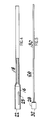
- Fig. 3 is a partial side view of a recipient site harvester according to the present invention.
- Fig. 4 is a cut-away side view of the recipient site harvester of Fig. 3.
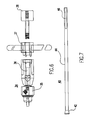
- Fig. 5 is a side view of a collared pin according to the present invention.
- Fig. 6 is a cut-away side view of a driver/extractor handle according to the present invention.
- Fig. 7 is a side view of a graft sizer/tamp according to the present invention.
- Fig. 8 illustrates chondral defect size determination and surgical planning
- Fig. 9 illustrates donor harvester tube impaction
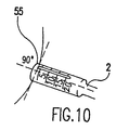
- Fig. 10 illustrates proper alignment of the donor harvester tube
- Fig. 11 illustrates donor core harvesting
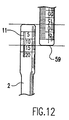
- Figs. 12 illustrates bone core sizing
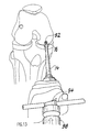
- Fig. 13 illustrates recipient socket harvester impaction
- Fig. 14 illustrates recipient socket depth control
- Fig. 15 illustrates recipient socket core extraction
- Fig. 16 illustrates recipient socket sizing and preparation
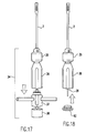
- Fig. 17 illustrates assembly preparation of the driver/extractor of the present invention.
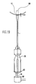
- Fig. 18 illustrates preparation of the driver/extractor and donor core harvester for insertion in the recipient site
- Fig. 19 illustrates donor core insertion
- Fig. 20 illustrates insertion of the donor core
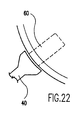
- Fig. 21 illustrates final donor core seating
- Fig. 22 is a detailed closeup of the donor core seating step of Fig. 21.
- Fig. 23 illustrates a completed transplantation
- Fig. 24 illustrates multiple transfers
- Fig. 25 illustrates multiple transfers
- the donor graft harvester 2 includes a hollow tube 4 attached to a cannulated handle 6 .
- the graft harvester tube has a sharp cutting edge 8 formed on the distal end thereof.
- the sharp edge is formed by a beveled surface 10 sloping inward distally from the outer surface to the inner surface of tube 4 .
- the donor harvester preferably is provided in a range of sizes. Accordingly, the inner diameters of hollow tubes 4 are, for example, 5, 6, 7, 8, and 9 millimeters.
- the walls of the harvester tubes are typically 0.5 millimeter thick. The thin walls minimize bone and tissue damage.
- windows 11 and depth markings 12 are provided on the tube of the donor site harvester to assist the surgeon during insertion of the harvester into the bone at the donor site.
- a longitudinal marking line (not shown) provided at the tip of each harvester facilitates core alignment in the recipient socket.
- Windows 11 allow for arthroscopic confirmation of donor bone plug extraction prior to complete removal of the donor harvester, as discussed below. In addition, windows 11 allow a comparison of overall core length between donor and recipient cores. Windows 11 also allow visual control of core insertion depth by calibrating the collar and tube laser marks. Also, windows 11 provide increased surface friction between the tube and the osteochondral core to ensure core extraction, especially at lengths over 10 mm.
- the recipient site harvester includes a hollow tube 16 attached to a cannulated handle 18 .
- the harvester has a sharp cutting edge 20 formed on the distal end of tube 16 .
- the sharp edge is formed by a beveled surface 22 sloping outward distally from the inner surface to the outer surface of tube 16 . See Fig. 4.
- the recipient site harvester also is provided in a range of sizes. Accordingly, the outer diameters of hollow tubes 16 are, for example, 5, 6, 7, 8, and 9 millimeters, in correspondence with the inner diameter of the associated donor graft harvester described above. As with the donor harvester, the walls of the recipient harvester tubes are thin, and windows 23 and depth markings 24 are provided on the tube, in a manner and for reasons similar to those described above with respect to donor harvester 2 .
- Pin 26 is made up of a collar 28 disposed on a distal end of a handle 30 .
- the surface 32 at the distal end of collar 28 is smooth and concave for enhanced biomechanics and to prevent damage to the cartilaginous surface of the graft core, similar to that of the sizer/tamp, described below.
- Pin 26 having a collar 28 of appropriate size approximating the inner diameter of the harvester, is received within handle 6 of the donor graft harvester, or handle 18 of the recipient site harvester, prior to insertion of the respective harvester into the selected harvesting or donation site. Accordingly, the proximal end of pin 28 is inserted through hollow tube 4 , 16 , respectively, such that the collar is disposed within the tube prior to harvesting cores at the donor graft or recipient sites.
- the proximal end of the pin extends beyond the proximal end of the harvester to an extent at least equal to the length of the tube, such that the harvested core can be removed easily from the lumen of the harvester tube by urging the handle of the collared pin distally to advance the harvested core.
- the harvesters of the present invention are similar to the coring reamer of co-owned U.S. Patent No. 5,423,823, the disclosure of which is incorporated herein by reference, and the bone harvester disclosed in co-owned U.S. Patent No. 5,603,716.
- a tube harvester driver/extractor 34 according to the present invention is shown.
- Cannulated tube harvester driver/extractor 34 preferably is assembled of three sections including a chuck end 36 , a handle 37 and an impact end 38 .
- Chuck 35 at the distal end of driver/extractor 34 secures onto the proximal end of harvesters 2 , 14 , and is cannulated to receive the proximal end of pin 26 .
- Removable handle 37 is used to manipulate the driver/extractor assembly.
- impact end 38 is struck with a mallet to drive the harvester/driver assembly into the selected harvesting site.
- end 38 and handle 37 Upon removal of end 38 and handle 37 , the proximal end of pin 28 of collared pin 26 is exposed for removal of the harvested cores from the harvester tubes, also set forth more fully below.
- the entire driver/extractor can be removed from the harvester prior to transfer.
- Sizer/tamp 40 has a tamp head 42 disposed on a shaft 44 .
- Three flats 46 are formed on the proximal end so that sizer/tamp 40 can be chucked into driver/ extractor 34 .
- the core-contacting surface at the distal end of the sizer/tamp is smooth and has a spherical concavity, similar to that of the collared pin discussed above.
- the spherical concavity of the sizer/tamp differs from that of the collared pin in that the outer edge of the concavity extends to and coincides with the outer diameter of the sizer/tamp.
- FIG. 8 an anterior aspect of a right knee 50 is shown diagrammatically.
- a chondral defect 52 in femoral condyle 54 is inspected arthroscopically and the extent of the lesion assessed with sizer/tamp 40 .
- Tamp 40 has the appropriate 5, 6, 7, 8, or 9 mm diameter Delrin head, which correlates with the diameter of the cutting tube harvesters.
- a tamp 40 of appropriate size also can be used to evaluate potential harvest donor sites, such as site 55 , in an area 56 along the outer edges of the non-articulating margin of the lateral femoral condyle above the sulcus terminalis or directly adjacent to the superolateral margin 57 of the intraarticular notch.
- Surgical planning with respect to transferring single or multiple osteochondral cores, appropriate osteochondral core diameter, and whether to proceed with an arthroscopic versus an open procedure must be assessed prior to further surgical transplantation intervention.
- Selection and size of single or multiple core grafts should be based on harvest site accessibility and the convex/concave surface shape relationship of the available donor and recipient sites.
- the appropriate, single-use tube harvester set of one-each donor harvester 2 and one-each recipient harvester 14 with respective collared pins 26 is selected based on defect and harvest site measurements.
- the donor tube harvester is selected to have an outer diameter 1 mm larger than the recipient tube harvester.
- the inner diameter of the donor tube is thus equal to the recipient outer tube diameter to assure a press fit fixation of the donor core in the recipient site.
- Tube harvester sets consist of 5 and 6 mm, 6 and 7 mm, 7 and 8 mm, 8 and 9 mm, or 9 and 10 mm sizes.
- the donor tube harvester 2 of the appropriate diameter and labeled "DONOR" is inserted fully into the tube harvester driver/extractor 34 (see Fig. 6) and placed over the hyaline cartilage harvest site 55. Care must be taken to adjust the insertion and/or knee flexion angle so that the tube harvester end is flush with the articular cartilage prior to impaction. See Fig. 10.
- the tube harvester is driven into subchondral bone with a mallet 58 to a depth of approximately 15 mm. Care should be taken not to rotate the harvester during insertion so as to avoid damaging the core to be harvested.
- a slotted cannula (not shown) may be used to facilitate larger diameter tube harvester insertion into the joint. After insertion, the slotted cannula is pulled back along the tube harvester shaft and removed sideways through the slot to increase intraarticular visualization, tube harvester mobility, and fluid distension.
- driver/extractor 34 is rotated, preferably about 90° clockwise, about 90° counter-clockwise, and then gently rocked, superior and inferior, to fracture the cancellous base for removal of the osteochondral core.
- Donor tube harvester 2 is then retrograded from the donor site with the harvested core captured within the tube.
- the harvested core can be visualized through windows 11 to verify that the core has been captured successfully within the harvester. If rotation and extraction of the tube harvester should fail to capture the core for removal, reinsertion and further impaction of the tube harvester up to 20 mm with subsequent rotation and extraction steps may be indicated.
- the donor tube harvester 2 and the captured core are removed from the driver/extractor and placed in a secure, sterile holding area.
- the appropriately-sized tube harvester 14 labeled "RECIPIENT” and collared pin 26 from the tube harvester set are inserted fully into the tube harvester driver/extractor 34 . If a single core transfer is indicated to replace the surface of the defect 52 , recipient tube harvester 14 is placed over the defect and driven into the subchondral bone with mallet 58 . Again, rotation of the recipient harvester is avoided during insertion of the harvester, as noted above with respect to insertion of the donor harvester.
- the preferred depth of about 13 mm. is determined with the tube harvester millimeter depth markings 24 on the outer surface of tube 16 , as shown in Fig. 14.
- a longitudinal marking line (not shown) at the tip of each tube harvester should be rotated to align with the leading cutting edge into cartilage during donor core harvesting.
- Recipient harvesting should be performed at an angle as close as possible to the angle used during donor core harvesting. This facilitates close approximation of the angled hyaline cartilage donor surface with the surrounding cartilage of the angled recipient socket by aligning the longitudinal marking line and leading cutting edge of the donor tube against the recipient socket rim during donor core insertion.
- the tube harvester driver/extractor 34 is rotated and gently rocked, as with the donor harvester above, to fracture the cancellous bone at the distal end of the tube. Extraction of the tube harvester and core can be facilitated by simultaneous counter rotation and extraction of the tube driver so as to form recipient socket 60 .
- the lengths of the donor and recipient cores can be compared directly by placing the donor and recipient harvesters side by side.
- the harvested cores can be visualized through windows 11 and 23 in the donor and recipient harvesters, respectively. Adjustments to the length of the harvester autograft donor core can be made accordingly.
- the distal end of the donor core is smoothed prior to insertion into the recipient site.
- calibrated alignment stick 59 of an appropriate diameter can be used to measure the depth of recipient socket 60 .
- the alignment stick also can align correctly the angle of the recipient socket with respect to the position of an insertion portal when an arthroscopic approach is used.
- the alignment stick also can be used to fine tune the recipient socket length as desired to match the length of the donor core. Accordingly, alignment stick 59 is impacted with mallet 58 until the desired depth is achieved.
- the recipient tube harvester 14 is replaced with the 1 mm diameter-larger donor tube harvester 2 and collared pin with the captured autograft core.
- the donor tube harvester is inserted fully into the tube harvester driver/extractor 34 .
- the driver/extractor impaction cap 38 is unscrewed and the T-handled midsection 37 is removed. Accordingly, the proximal end of collared pin 26 is exposed, which is used to advance the core into the recipient socket 60 .
- a stainless steel pin calibrator 62 is applied onto the open handle end for protection during further impaction, to maintain alignment of the collared pin, and to provide mechanical control of the bone core insertion.
- the pin calibrator preferably has an O-ring that press fits into the handle, and a small hole in the center that is threaded, so that the calibrator can be pulled out of the handle with a threaded retriever.
- the distal end of donor harvester 2 is inserted into recipient site 60 .
- the beveled surface 10 helps to guide the harvester at the recipient site and assists in providing a secure fit and alignment of the donor harvester.
- a mallet is used to tap lightly onto the proximal end of handle 28 of collared pin 26 to drive the core into the recipient socket 60 while maintaining stable positioning of the harvester tube and knee flexion angle.
- the core is advanced so that 1 mm of core remains proud, as shown in Figs. 19 and 20. Accordingly, the collared pin 26 is advanced until the end of the pin is flush with the pin calibrator 62 .
- the pre-determined length of the collared pin is designed to advance the bone core so that 1 mm of the graft will be exposed outside the recipient socket when the pin is driven flush with the end of the proximal face of the pin calibrator. Control of the core insertion also can be obtained by visualizing the core and collared pin advancement through windows 11 in the side of the harvester.
- sizer/tamp 40 is chucked into driver/harvester 34 for seating the core flush with the surrounding hyaline cartilage.
- the sizer/tamp diameter is at least 1 mm larger than the diameter of the core.
- the larger diameter tamp provides complete control of proper core insertion depth flush to surrounding articular cartilage and eliminates any potential of overdriving.
- sizer/tamp 40 is the same as that used to determine the core size required, and is the same size as the osteochondral core.
- the tamp is used in an off-center position with respect to the core, so that the overhanging edge of the sizer/tamp encounters the surrounding cartilage area and prevents overinsertion of the bone core.
- the face of the core is seated flush with the surrounding cartilage surface, which is achieved by light tapping with the mallet 58 .
- the completed transfer is shown in Fig. 23.
- each core transfer should be completed prior to proceeding with further recipient socket creation. See Figs. 24 and 25. This prevents potential recipient tunnel wall fracture and allows subsequent cores to be placed directly adjacent to previously inserted cores when desired.
- Donor sockets 64 are routinely left open after harvesting and fill in with cancellous bone and fibrocartilage within 8 to 12 weeks.
- cancellous bone harvested from the defect may be inserted into donor sites, and should be tamped firmly into the donor socket with a sizer/tamper or alignment stick to compress the cancellous bone for enhanced fixation.
Abstract
Description
| Size | Diameter | Radius [metric] |
| 5 mm | .151 [ 3.84] | .109 [ 2.74] |
| 6 | .191 [ 4.85] | .229 [ 5.82] |
| 7 | .230 [ 5.84] | .385 [ 9.78] |
| 8 | .269 [ 6.83] | .580 [14.73] |
| 9 | .309 [ 7.85] | .831 [21.11] |
| 10 | .348 [ 8.84] | 1.090 [27.69] |
| 11 | .387 [ 9.83] | 1.410 [35.81] |
| 12 | .427 [10.85] | 1.754 [44.55] |
| 13 | .466 [11.84] | 2.144 [54.46] |
| 14 | .506 [12.85] | 2.578 [65.48] |
| 15 | .545 [13.85] | 3.046 [77.37] |
| Size | Diameter | Radius [metric] |
| 5 mm | .197 [ 5.0] | .29 [ 7.4] |
| 6 | .236 [ 6.0] | .46 [11.7] |
| 7 | .276 [ 7.0] | .68 [17.3] |
| 8 | .315 [ 8.0] | .94 [23.9] |
| 9 | .354 [ 9.0] | 1.22 [31.0] |
| 10 | .394 [10.0] | 1.55 [39.4] |
Advantageously, the alignment stick also can be used to fine tune the recipient socket length as desired to match the length of the donor core. Accordingly,
Claims (5)
- Apparatus for transplanting osteochondral cores in a joint, the apparatus comprising:
a cutting tube having a sharp cutting edge on a distal end and a cannulated handle on a proximal end; and a pin having a distal end and a proximal end disposed slidably within the cutting tube, the pin having a collar, with a smooth distal surface, disposed on the distal end of the pin, and a handle on the proximal end of the pin, the handle being disposed slidably within the cannulated handle of the cutting tube. - The apparatus of claim 1, further comprising a lumen, and a window in a side of the cutting tube for visualizing the lumen.
- The apparatus of claim 1 or 2, wherein the sharp cutting edge is smooth.
- The apparatus of any preceding claim, further comprising a driver removably secured to the cutting tube.
- An apparatus for transplanting osteochondral cores in a joint, the apparatus comprising:a core-cutting tube, having a sharp cutting edge on a distal end, a cannulated handle on a proximal end, and an inner diameter;a socket-cutting tube, having a sharp cutting edge on a distal end, a cannulated handle on a proximal end, and an outer diameter equal to the inner diameter of the core cutting tube; anda pin disposed slidably within each of the cutting tubes, each pin having a distal end and a proximal end, each pin having a collar with a smooth distal surface disposed on the distal end of the pin, and a handle disposed on the proximal end of the pin, the handle being disposed slidably within the cannulated handle of each of the cutting tubes, respectively.
Applications Claiming Priority (4)
| Application Number | Priority Date | Filing Date | Title |
|---|---|---|---|
| US2404596P | 1996-08-16 | 1996-08-16 | |
| US24045P | 1996-08-16 | ||
| US885752P | 1997-06-03 | ||
| US08/885,752 US5919196A (en) | 1995-02-16 | 1997-06-30 | Method and apparatus for osteochondral autograft transplantation |
Publications (3)
| Publication Number | Publication Date |
|---|---|
| EP0824893A2 true EP0824893A2 (en) | 1998-02-25 |
| EP0824893A3 EP0824893A3 (en) | 1998-04-29 |
| EP0824893B1 EP0824893B1 (en) | 2005-11-09 |
Family
ID=26697964
Family Applications (1)
| Application Number | Title | Priority Date | Filing Date |
|---|---|---|---|
| EP97306035A Expired - Lifetime EP0824893B1 (en) | 1996-08-16 | 1997-08-08 | Apparatus for osteochondral autograft transplantation |
Country Status (5)
| Country | Link |
|---|---|
| US (1) | US5919196A (en) |
| EP (1) | EP0824893B1 (en) |
| JP (1) | JP3932496B2 (en) |
| AU (1) | AU717552B2 (en) |
| DE (1) | DE69734550T2 (en) |
Cited By (20)
| Publication number | Priority date | Publication date | Assignee | Title |
|---|---|---|---|---|
| WO1998034569A1 (en) * | 1997-02-11 | 1998-08-13 | Smith & Nephew, Inc. | Repairing cartilage |
| EP0990421A1 (en) * | 1998-09-29 | 2000-04-05 | Sulzer Orthopädie AG | Hollow mill for tissue |
| EP1038509A1 (en) * | 1999-03-23 | 2000-09-27 | Sulzer Orthopedics Ltd. | Instrument, set of instruments as well as process for inserting an osteochondral graft |
| US6193722B1 (en) * | 1998-09-29 | 2001-02-27 | Sulzer Orthopaedic Ag | Hollow milling tool |
| US6306142B1 (en) | 1998-07-17 | 2001-10-23 | Johnson & Johnson | Method and apparatus for harvesting and implanting bone plugs |
| EP1175870A1 (en) | 2000-07-26 | 2002-01-30 | Sulzer Orthopedics Ltd. | Hollow drills for obtaining bone material |
| US6375658B1 (en) | 2000-04-28 | 2002-04-23 | Smith & Nephew, Inc. | Cartilage grafting |
| WO2002003867A3 (en) * | 2000-07-06 | 2002-04-25 | David A Hansson | Bone preparation instruments |
| US6530928B1 (en) | 1999-03-23 | 2003-03-11 | Sulzer Orthopedics Ltd. | Instrument, instrument set and a method for the introduction of an osteochondral transplant |
| US6635060B2 (en) | 2000-07-06 | 2003-10-21 | Sulzer Spine-Tech Inc. | Bone preparation instruments and methods |
| WO2005077292A1 (en) | 2004-02-17 | 2005-08-25 | Politecnico Di Milano | Method and instrument for the geometrical evaluation of lesions affecting tissues or internal organs |
| EP1698307A1 (en) * | 2005-03-03 | 2006-09-06 | Karl Storz GmbH & Co. KG | Medical instrument for autologous chondrocyte transplantation |
| US7569059B2 (en) | 2005-04-20 | 2009-08-04 | Arthroscopic Innovations Llc | Method and apparatus for surgical repair |
| US7819888B2 (en) | 2001-10-23 | 2010-10-26 | Innovasive Devices, Inc. | Method and apparatus for harvesting and implanting bone plugs |
| US8435305B2 (en) | 2010-08-31 | 2013-05-07 | Zimmer, Inc. | Osteochondral graft delivery device and uses thereof |
| US8801725B2 (en) | 2008-03-10 | 2014-08-12 | Zimmer Orthobiologics, Inc. | Instruments and methods used when repairing a defect on a tissue surface |
| US9113916B2 (en) | 2010-08-31 | 2015-08-25 | Zimmer, Inc. | Drill bit for osteochondral drilling with guiding element and uses thereof |
| US9277945B2 (en) | 2012-02-07 | 2016-03-08 | Mnr Device Corporation | Method and apparatus for treating a bone fracture |
| CN108742868A (en) * | 2018-07-03 | 2018-11-06 | 杭州埃杜医疗科技有限公司 | A kind of cartilage transplantation prosthesis instrument packet |
| US11871940B2 (en) | 2018-11-27 | 2024-01-16 | Sunnybrook Research Institute | Cartilage slicing apparatus and methods therefor |
Families Citing this family (116)
| Publication number | Priority date | Publication date | Assignee | Title |
|---|---|---|---|---|
| US6241734B1 (en) * | 1998-08-14 | 2001-06-05 | Kyphon, Inc. | Systems and methods for placing materials into bone |
| US5954671A (en) * | 1998-04-20 | 1999-09-21 | O'neill; Michael J. | Bone harvesting method and apparatus |
| EP1237511B1 (en) | 1999-12-15 | 2004-09-01 | Sulzer Orthopedics Ltd. | Preparation for repairing cartilage defects or cartilage/bone defects in human or animal joints |
| US6591581B2 (en) * | 2000-03-08 | 2003-07-15 | Arthrex, Inc. | Method for preparing and inserting round, size specific osteochondral cores in the knee |
| US6520964B2 (en) | 2000-05-01 | 2003-02-18 | Std Manufacturing, Inc. | System and method for joint resurface repair |
| US20040230315A1 (en) * | 2000-05-01 | 2004-11-18 | Ek Steven W. | Articular surface implant |
| US6610067B2 (en) | 2000-05-01 | 2003-08-26 | Arthrosurface, Incorporated | System and method for joint resurface repair |
| US7163541B2 (en) | 2002-12-03 | 2007-01-16 | Arthrosurface Incorporated | Tibial resurfacing system |
| US8177841B2 (en) | 2000-05-01 | 2012-05-15 | Arthrosurface Inc. | System and method for joint resurface repair |
| US7713305B2 (en) | 2000-05-01 | 2010-05-11 | Arthrosurface, Inc. | Articular surface implant |
| US7678151B2 (en) | 2000-05-01 | 2010-03-16 | Ek Steven W | System and method for joint resurface repair |
| US6488033B1 (en) * | 2000-05-15 | 2002-12-03 | Cryolife, Inc. | Osteochondral transplant techniques |
| US7548865B2 (en) * | 2000-10-20 | 2009-06-16 | Arthrex, Inc. | Method of selling procedure specific allografts and associated instrumentation |
| CA2365376C (en) | 2000-12-21 | 2006-03-28 | Ethicon, Inc. | Use of reinforced foam implants with enhanced integrity for soft tissue repair and regeneration |
| BR0116641A (en) * | 2000-12-28 | 2004-02-17 | Fidia Advanced Biopolymers S P | Use of a biological material containing three-dimensional frames of hyaluronic acid derivatives for arthroscopic implant preparation and an instrument kit for insertion of said biological material by arthroscopy |
| US6833005B1 (en) | 2001-02-02 | 2004-12-21 | John P. Mantas | Ligament graft system and method |
| CA2458753A1 (en) * | 2001-08-27 | 2003-03-06 | The Cleveland Clinic Foundation | Compositions, methods and apparatus for surgical procedures |
| US20030055316A1 (en) * | 2001-09-19 | 2003-03-20 | Brannon James Kevin | Endoscopic bone debridement |
| US8328716B2 (en) * | 2002-05-23 | 2012-12-11 | Arthrex, Inc. | Retracting cannula |
| US7591820B2 (en) * | 2002-08-09 | 2009-09-22 | Arthrex, Inc. | Retrograde osteochondral autograft transfer system |
| US7959636B2 (en) * | 2002-08-15 | 2011-06-14 | Arthrex, Inc. | Osteochondral repair using plug fashioned from whole distal femur or condyle formed of hydrogel composition |
| US7264634B2 (en) * | 2002-09-20 | 2007-09-04 | Arthrex, Inc. | Method and instrumentation for osteochondral repair using preformed implants |
| US7402319B2 (en) * | 2002-09-27 | 2008-07-22 | Board Of Regents, The University Of Texas System | Cell-free tissue replacement for tissue engineering |
| US7172598B2 (en) * | 2002-09-30 | 2007-02-06 | Depuy Products, Inc. | Force specific impacting device |
| US20040078090A1 (en) | 2002-10-18 | 2004-04-22 | Francois Binette | Biocompatible scaffolds with tissue fragments |
| US7901408B2 (en) | 2002-12-03 | 2011-03-08 | Arthrosurface, Inc. | System and method for retrograde procedure |
| US20070043376A1 (en) * | 2003-02-21 | 2007-02-22 | Osteobiologics, Inc. | Bone and cartilage implant delivery device |
| WO2004075727A2 (en) * | 2003-02-21 | 2004-09-10 | Osteobiologics, Inc. | Bone and cartilage implant delivery device |
| US8388624B2 (en) | 2003-02-24 | 2013-03-05 | Arthrosurface Incorporated | Trochlear resurfacing system and method |
| US7160305B2 (en) * | 2003-03-07 | 2007-01-09 | Arthrex, Inc. | Retrodrill technique for insertion of autograft, allograft or synthetic osteochondral implants |
| US8187336B2 (en) * | 2003-06-16 | 2012-05-29 | Jamali Amir A | Device and method for reconstruction of osseous skeletal defects |
| US8226715B2 (en) | 2003-06-30 | 2012-07-24 | Depuy Mitek, Inc. | Scaffold for connective tissue repair |
| US10583220B2 (en) | 2003-08-11 | 2020-03-10 | DePuy Synthes Products, Inc. | Method and apparatus for resurfacing an articular surface |
| US8162967B1 (en) * | 2003-10-16 | 2012-04-24 | Biomet Sports Medicine Llc | Method and apparatus for coring and reaming of bone |
| WO2006074321A2 (en) | 2003-11-20 | 2006-07-13 | Arthrosurface, Inc. | System and method for retrograde procedure |
| US7951163B2 (en) | 2003-11-20 | 2011-05-31 | Arthrosurface, Inc. | Retrograde excision system and apparatus |
| WO2005051231A2 (en) | 2003-11-20 | 2005-06-09 | Arthrosurface, Inc. | Retrograde delivery of resurfacing devices |
| US7316822B2 (en) | 2003-11-26 | 2008-01-08 | Ethicon, Inc. | Conformable tissue repair implant capable of injection delivery |
| WO2005070333A1 (en) | 2004-01-13 | 2005-08-04 | Orthobiologica, Inc. | Drug delivery to a joint |
| US11395865B2 (en) | 2004-02-09 | 2022-07-26 | DePuy Synthes Products, Inc. | Scaffolds with viable tissue |
| US20070185585A1 (en) * | 2004-03-09 | 2007-08-09 | Brat Bracy | Implant Scaffold Combined With Autologous Tissue, Allogenic Tissue, Cultured Tissue, or combinations Thereof |
| EP1737506A4 (en) * | 2004-03-09 | 2011-05-18 | Osteobiologics Inc | Implant scaffold combined with autologous or allogenic tissue |
| US7488327B2 (en) | 2004-04-12 | 2009-02-10 | Synthes (U.S.A.) | Free hand drill guide |
| CA2572584A1 (en) | 2004-06-28 | 2006-01-12 | Arthrosurface, Inc. | System for articular surface replacement |
| US20060030940A1 (en) * | 2004-07-20 | 2006-02-09 | Reinhold Schmieding | Use of autogenous growth factors in bone tunnels during ligament reconstruction with mechanical containment implants |
| US8043315B2 (en) * | 2004-09-23 | 2011-10-25 | Arthrex, Inc. | Osteochondral repair using plug fashioned from partial distal allograft femur or condyle |
| US7828853B2 (en) | 2004-11-22 | 2010-11-09 | Arthrosurface, Inc. | Articular surface implant and delivery system |
| AU2006210847A1 (en) * | 2005-02-01 | 2006-08-10 | Osteobiologics, Inc. | Method and device for selective addition of a bioactive agent to a multi-phase implant |
| US8672941B2 (en) * | 2005-02-02 | 2014-03-18 | Kensey Nash Bvf Technology Llc | Coring device for preserving living tissue |
| EP1700582A3 (en) * | 2005-03-09 | 2010-05-26 | Allograft Tissue Systems, Inc. | Osteochondral core centrifugation system |
| AU2006282079B2 (en) * | 2005-04-20 | 2011-12-01 | Arthroscopic Innovations Llc | Suture fixation device and method for surgical repair |
| JP5007967B2 (en) * | 2005-07-05 | 2012-08-22 | 学校法人日本大学 | Cannula |
| US7371260B2 (en) * | 2005-10-26 | 2008-05-13 | Biomet Sports Medicine, Inc. | Method and instrumentation for the preparation and transplantation of osteochondral allografts |
| US8357181B2 (en) | 2005-10-27 | 2013-01-22 | Warsaw Orthopedic, Inc. | Intervertebral prosthetic device for spinal stabilization and method of implanting same |
| DE602006016904D1 (en) * | 2005-11-10 | 2010-10-28 | Arthrex Inc | Apparatus for reconstructing the anterior cruciate ligament using a drill for the retrograde shaping of canals |
| US8394100B2 (en) * | 2005-12-23 | 2013-03-12 | Warsaw Orthopedic, Inc. | Surgical apparatus and method for manipulating one or more osteochondral plugs |
| US8083795B2 (en) | 2006-01-18 | 2011-12-27 | Warsaw Orthopedic, Inc. | Intervertebral prosthetic device for spinal stabilization and method of manufacturing same |
| US7776043B2 (en) * | 2006-01-26 | 2010-08-17 | Warsaw Orthopedic, Inc. | Osteochondral implant fixation procedure and bone dilator used in same |
| US7722614B2 (en) * | 2006-01-27 | 2010-05-25 | Warsaw Orthopedic, Inc, | Osteochondral implant fixation method |
| US8221423B2 (en) * | 2006-03-28 | 2012-07-17 | Warsaw Orthopedic, Inc. | Osteochondral plug graft harvesting instrument and kit |
| US20070276506A1 (en) * | 2006-05-25 | 2007-11-29 | Biomet Manufacturing Corp. | Demineralized osteochondral plug |
| JP4816281B2 (en) * | 2006-06-22 | 2011-11-16 | 富士ゼロックス株式会社 | Document use management system, document management server and program thereof |
| US7594930B2 (en) * | 2006-07-06 | 2009-09-29 | General Patent Llc | Method of attaching soft tissue to bone |
| US7985230B2 (en) * | 2006-07-27 | 2011-07-26 | Warsaw Orthopedic, Inc. | System and method of harvesting osteochondral plugs |
| US20080051677A1 (en) * | 2006-08-23 | 2008-02-28 | Warsaw Orthopedic, Inc. | Method and apparatus for osteochondral autograft transplantation |
| US7747306B2 (en) | 2006-09-01 | 2010-06-29 | Warsaw Orthopedic, Inc. | Osteochondral implant procedure |
| US8043377B2 (en) | 2006-09-02 | 2011-10-25 | Osprey Biomedical, Inc. | Implantable intervertebral fusion device |
| US7879040B2 (en) * | 2006-10-23 | 2011-02-01 | Warsaw Orthopedic, IN | Method and apparatus for osteochondral autograft transplantation |
| US8852192B2 (en) * | 2006-11-13 | 2014-10-07 | Warsaw Orthopedic, Inc. | Method and apparatus for osteochondral autograft transplantation |
| DE102006057524B4 (en) * | 2006-12-06 | 2016-05-19 | Continental Automotive Gmbh | Method for adapting a drag coefficient of a flow control valve |
| AU2007332787A1 (en) | 2006-12-11 | 2008-06-19 | Arthrosurface Incorporated | Retrograde resection apparatus and method |
| US8118814B2 (en) * | 2007-02-14 | 2012-02-21 | Depuy Mitek Inc. | Implement for orientating a tool, particularly useful in surgical tools for harvesting and implanting bone plugs to repair damaged bone tissue |
| US7780668B2 (en) * | 2007-03-02 | 2010-08-24 | Musculoskeletal Transplant Foundation | Osteochondral allograft cartilage transplant workstation |
| US7875032B2 (en) * | 2007-04-13 | 2011-01-25 | Warsaw Orthopedic, Inc. | Osteochondral autograft transplantation procedure and apparatus |
| US20090054906A1 (en) * | 2007-08-24 | 2009-02-26 | Zimmer Orthobiologics, Inc. | Medical device and method for delivering an implant to an anatomical site |
| US8322256B2 (en) * | 2007-10-05 | 2012-12-04 | Biomet Manufacturing Corp. | System for forming a tendon-bone graft |
| US8303592B2 (en) * | 2007-10-05 | 2012-11-06 | Biomet Manufacturing Corp. | System for forming a tendon-bone graft |
| US8128647B2 (en) * | 2007-11-14 | 2012-03-06 | Kennedy John S | Surgical instrument for detecting, isolating and excising tumors |
| US20090125035A1 (en) * | 2007-11-14 | 2009-05-14 | Kennedy John S | Surgical Cutting Instrument for Breast Surgery |
| US8998918B2 (en) * | 2008-02-12 | 2015-04-07 | Amir Jamali | Device and method for allograft and tissue engineered osteochondral graft surface matching, preparation, and implantation |
| US8439921B2 (en) * | 2008-02-12 | 2013-05-14 | Amir Jamali | Device and method for allograft total hip arthroplasty |
| EP2262448A4 (en) | 2008-03-03 | 2014-03-26 | Arthrosurface Inc | Bone resurfacing system and method |
| US8152846B2 (en) * | 2008-03-06 | 2012-04-10 | Musculoskeletal Transplant Foundation | Instrumentation and method for repair of meniscus tissue |
| US8152808B2 (en) * | 2008-05-30 | 2012-04-10 | Musculoskeletal Transplant Foundation | Surgical bone cutting assembly and method of using same |
| US8486074B2 (en) * | 2008-06-02 | 2013-07-16 | Musculoskeletal Transplant Foundation | Surgical allograft bone plug cutting tool assembly and method of using same |
| GB2465631A (en) * | 2008-11-28 | 2010-06-02 | Orthomimetics Ltd | Arthroscope with depth gauge |
| CA2759027C (en) | 2009-04-17 | 2020-02-25 | Arthrosurface Incorporated | Glenoid resurfacing system and method |
| US10945743B2 (en) | 2009-04-17 | 2021-03-16 | Arthrosurface Incorporated | Glenoid repair system and methods of use thereof |
| WO2010121250A1 (en) | 2009-04-17 | 2010-10-21 | Arthrosurface Incorporated | Glenoid resurfacing system and method |
| US8419739B2 (en) * | 2009-08-24 | 2013-04-16 | Amir A. Jamali | Method and apparatus for allograft disc transplantation |
| EP2338530B1 (en) | 2009-12-22 | 2015-04-22 | Arthrex, Inc. | Hybrid polymer/metal plug for treating chondral defects |
| US9220554B2 (en) | 2010-02-18 | 2015-12-29 | Globus Medical, Inc. | Methods and apparatus for treating vertebral fractures |
| AU2011222404A1 (en) | 2010-03-05 | 2012-09-27 | Arthrosurface Incorporated | Tibial resurfacing system and method |
| US8641718B2 (en) | 2010-10-19 | 2014-02-04 | Biomet Manufacturing, Llc | Method and apparatus for harvesting cartilage for treatment of a cartilage defect |
| US9066716B2 (en) | 2011-03-30 | 2015-06-30 | Arthrosurface Incorporated | Suture coil and suture sheath for tissue repair |
| US9381021B2 (en) * | 2011-09-23 | 2016-07-05 | Biomet Sports Medicine, Llc | Method and apparatus for forming a hole in bone during a surgical procedure |
| WO2013096746A1 (en) | 2011-12-22 | 2013-06-27 | Arthrosurface Incorporated | System and method for bone fixation |
| NZ701804A (en) * | 2012-04-11 | 2018-01-26 | Vad Scient Llc | Delivery device and system for cartilage repair, preservation and growth by stimulation of bone-chondral interface |
| US9468448B2 (en) | 2012-07-03 | 2016-10-18 | Arthrosurface Incorporated | System and method for joint resurfacing and repair |
| US9216022B2 (en) | 2013-02-15 | 2015-12-22 | Arthrex, Inc. | Methods and instruments for forming non-circular cartilage grafts |
| US9492200B2 (en) | 2013-04-16 | 2016-11-15 | Arthrosurface Incorporated | Suture system and method |
| US9968373B1 (en) * | 2014-02-21 | 2018-05-15 | Surgentec, Llc | Handles for needle assemblies |
| US10624748B2 (en) | 2014-03-07 | 2020-04-21 | Arthrosurface Incorporated | System and method for repairing articular surfaces |
| US20150250472A1 (en) | 2014-03-07 | 2015-09-10 | Arthrosurface Incorporated | Delivery System for Articular Surface Implant |
| US11607319B2 (en) | 2014-03-07 | 2023-03-21 | Arthrosurface Incorporated | System and method for repairing articular surfaces |
| EP3169261B1 (en) * | 2014-07-15 | 2021-11-10 | The General Hospital Corporation | Apparatus for tissue copying and grafting |
| US10485558B1 (en) | 2015-07-31 | 2019-11-26 | Joshua Cook | Apparatus and method for harvesting bone |
| IT201600094601A1 (en) * | 2016-09-21 | 2018-03-21 | Fin Ceram Faenza S P A | "EQUIPMENT AND KIT FOR THE PRODUCTION OF CONTROLLED DEPTH HOLES AND OF DIFFERENT DIAMETER ON CONDRAL AND OSTEOCONDRAL SURFACES" |
| US11123148B2 (en) | 2016-10-14 | 2021-09-21 | Riley WILLIAMS | Coordinated sizer-punch tool for articular cartilage repair |
| US11160663B2 (en) | 2017-08-04 | 2021-11-02 | Arthrosurface Incorporated | Multicomponent articular surface implant |
| US20210267769A1 (en) * | 2018-06-25 | 2021-09-02 | Conmed Corporation | Ligament revision system |
| WO2020186099A1 (en) | 2019-03-12 | 2020-09-17 | Arthrosurface Incorporated | Humeral and glenoid articular surface implant systems and methods |
| CN113633342B (en) * | 2021-08-27 | 2023-01-31 | 首都医科大学附属北京天坛医院 | Improved skull drill for neurosurgery |
| US11660194B1 (en) | 2022-06-20 | 2023-05-30 | University Of Utah Research Foundation | Cartilage and bone harvest and delivery system and methods |
| US11523834B1 (en) | 2022-06-20 | 2022-12-13 | University Of Utah Research Foundation | Cartilage and bone harvest and delivery system and methods |
| US11759322B1 (en) | 2022-10-21 | 2023-09-19 | Sadat A. ALI | Method of treating osteoarthritis of the knee |
Citations (5)
| Publication number | Priority date | Publication date | Assignee | Title |
|---|---|---|---|---|
| US3848601A (en) * | 1972-06-14 | 1974-11-19 | G Ma | Method for interbody fusion of the spine |
| US4010737A (en) * | 1971-06-14 | 1977-03-08 | Vilaghy Miklos I | Bone biopsy instrument kit |
| WO1991006246A1 (en) * | 1989-11-06 | 1991-05-16 | Allen William C | Biopsy device |
| US5423823A (en) * | 1993-02-18 | 1995-06-13 | Arthrex Inc. | Coring reamer |
| DE19503504A1 (en) * | 1994-09-16 | 1996-03-21 | Metrimed Orvosi Mueszergyarto | Instrument set for osteochondral transplant |
Family Cites Families (20)
| Publication number | Priority date | Publication date | Assignee | Title |
|---|---|---|---|---|
| US493730A (en) * | 1893-03-21 | Trephine | ||
| US1911873A (en) * | 1931-07-21 | 1933-05-30 | Joseph Shapiro | Wafer cutting machine |
| US2573462A (en) * | 1947-09-02 | 1951-10-30 | Lindsey Earle | Tubular rotary cutter |
| US2591516A (en) * | 1950-05-08 | 1952-04-01 | Victor L Darnell | Dispensing device |
| US4007732A (en) * | 1975-09-02 | 1977-02-15 | Robert Carl Kvavle | Method for location and removal of soft tissue in human biopsy operations |
| US4177797A (en) * | 1977-03-04 | 1979-12-11 | Shelby M. Baylis | Rotary biopsy device and method of using same |
| US4059115A (en) * | 1976-06-14 | 1977-11-22 | Georgy Stepanovich Jumashev | Surgical instrument for operation of anterior fenestrated spondylodessis in vertebral osteochondrosis |
| US4649918A (en) * | 1980-09-03 | 1987-03-17 | Custom Medical Devices, Inc. | Bone core removing tool |
| US4741651A (en) * | 1986-04-25 | 1988-05-03 | Despres Roger J | Hole saw |
| US4913143A (en) * | 1986-05-28 | 1990-04-03 | The United States Of America As Represented By The Secretary Of The Air Force | Trephine assembly |
| US4782833A (en) * | 1987-02-19 | 1988-11-08 | Thomas A. Einhorn | Bone boring instrument |
| DE3850220D1 (en) * | 1987-11-18 | 1994-07-21 | Straumann Inst Ag | Device with a hollow milling cutter used to cut out a cartilage or bone cone and connected to a drive shaft in a rotationally fixed manner. |
| US5139520A (en) * | 1990-01-31 | 1992-08-18 | American Cyanamid Company | Method for acl reconstruction |
| US5152763A (en) * | 1991-04-02 | 1992-10-06 | Johnson Lanny L | Method for grafting bone |
| US5197967A (en) * | 1991-04-02 | 1993-03-30 | Synthes (U.S.A.) | Trephine instrument and method for cutting annular holes |
| US5116337A (en) * | 1991-06-27 | 1992-05-26 | Johnson Lanny L | Fixation screw and method for ligament reconstruction |
| US5211647A (en) * | 1992-02-19 | 1993-05-18 | Arthrex Inc. | Interference screw and cannulated sheath for endosteal fixation of ligaments |
| US5320626A (en) * | 1992-02-19 | 1994-06-14 | Arthrex Inc. | Endoscopic drill guide |
| US5269786A (en) * | 1992-02-20 | 1993-12-14 | Arthrex Inc. | PCL oriented placement tibial guide method |
| US5603716A (en) * | 1995-02-16 | 1997-02-18 | Arthrex Inc. | Method of ligament reconstruction using double socket graft placement and fixation |
-
1997
- 1997-06-30 US US08/885,752 patent/US5919196A/en not_active Expired - Lifetime
- 1997-08-08 DE DE69734550T patent/DE69734550T2/en not_active Expired - Lifetime
- 1997-08-08 EP EP97306035A patent/EP0824893B1/en not_active Expired - Lifetime
- 1997-08-14 AU AU34179/97A patent/AU717552B2/en not_active Expired
- 1997-08-18 JP JP22173997A patent/JP3932496B2/en not_active Expired - Lifetime
Patent Citations (5)
| Publication number | Priority date | Publication date | Assignee | Title |
|---|---|---|---|---|
| US4010737A (en) * | 1971-06-14 | 1977-03-08 | Vilaghy Miklos I | Bone biopsy instrument kit |
| US3848601A (en) * | 1972-06-14 | 1974-11-19 | G Ma | Method for interbody fusion of the spine |
| WO1991006246A1 (en) * | 1989-11-06 | 1991-05-16 | Allen William C | Biopsy device |
| US5423823A (en) * | 1993-02-18 | 1995-06-13 | Arthrex Inc. | Coring reamer |
| DE19503504A1 (en) * | 1994-09-16 | 1996-03-21 | Metrimed Orvosi Mueszergyarto | Instrument set for osteochondral transplant |
Cited By (30)
| Publication number | Priority date | Publication date | Assignee | Title |
|---|---|---|---|---|
| US6146385A (en) * | 1997-02-11 | 2000-11-14 | Smith & Nephew, Inc. | Repairing cartilage |
| WO1998034569A1 (en) * | 1997-02-11 | 1998-08-13 | Smith & Nephew, Inc. | Repairing cartilage |
| US6358253B1 (en) | 1997-02-11 | 2002-03-19 | Smith & Newhew Inc | Repairing cartilage |
| US6767354B2 (en) | 1998-07-17 | 2004-07-27 | Depuy Mitek, Inc. | Method and apparatus for harvesting and implanting bone plugs |
| US6395011B1 (en) | 1998-07-17 | 2002-05-28 | Johnson & Johnson | Method and apparatus for harvesting and implanting bone plugs |
| US6306142B1 (en) | 1998-07-17 | 2001-10-23 | Johnson & Johnson | Method and apparatus for harvesting and implanting bone plugs |
| US6193722B1 (en) * | 1998-09-29 | 2001-02-27 | Sulzer Orthopaedic Ag | Hollow milling tool |
| EP0990421A1 (en) * | 1998-09-29 | 2000-04-05 | Sulzer Orthopädie AG | Hollow mill for tissue |
| EP1038509A1 (en) * | 1999-03-23 | 2000-09-27 | Sulzer Orthopedics Ltd. | Instrument, set of instruments as well as process for inserting an osteochondral graft |
| US6530928B1 (en) | 1999-03-23 | 2003-03-11 | Sulzer Orthopedics Ltd. | Instrument, instrument set and a method for the introduction of an osteochondral transplant |
| US6375658B1 (en) | 2000-04-28 | 2002-04-23 | Smith & Nephew, Inc. | Cartilage grafting |
| US7192431B2 (en) | 2000-04-28 | 2007-03-20 | Smith & Nephew, Inc. | Cartilage grafting |
| WO2002003867A3 (en) * | 2000-07-06 | 2002-04-25 | David A Hansson | Bone preparation instruments |
| US6635060B2 (en) | 2000-07-06 | 2003-10-21 | Sulzer Spine-Tech Inc. | Bone preparation instruments and methods |
| US6641582B1 (en) | 2000-07-06 | 2003-11-04 | Sulzer Spine-Tech Inc. | Bone preparation instruments and methods |
| EP1175870A1 (en) | 2000-07-26 | 2002-01-30 | Sulzer Orthopedics Ltd. | Hollow drills for obtaining bone material |
| US7819888B2 (en) | 2001-10-23 | 2010-10-26 | Innovasive Devices, Inc. | Method and apparatus for harvesting and implanting bone plugs |
| WO2005077292A1 (en) | 2004-02-17 | 2005-08-25 | Politecnico Di Milano | Method and instrument for the geometrical evaluation of lesions affecting tissues or internal organs |
| EP1698307A1 (en) * | 2005-03-03 | 2006-09-06 | Karl Storz GmbH & Co. KG | Medical instrument for autologous chondrocyte transplantation |
| US7569059B2 (en) | 2005-04-20 | 2009-08-04 | Arthroscopic Innovations Llc | Method and apparatus for surgical repair |
| US7833230B2 (en) | 2005-04-20 | 2010-11-16 | Arthroscopic Innovations Llc | Method and apparatus for providing a passageway |
| US7833244B2 (en) | 2005-04-20 | 2010-11-16 | Arthroscopic Innovations Llc | Suture fixation device and method for surgical repair |
| US8801725B2 (en) | 2008-03-10 | 2014-08-12 | Zimmer Orthobiologics, Inc. | Instruments and methods used when repairing a defect on a tissue surface |
| US8435305B2 (en) | 2010-08-31 | 2013-05-07 | Zimmer, Inc. | Osteochondral graft delivery device and uses thereof |
| US8753406B2 (en) | 2010-08-31 | 2014-06-17 | Zimmer Inc. | Osteochondral graft delivery device and uses thereof |
| US9113916B2 (en) | 2010-08-31 | 2015-08-25 | Zimmer, Inc. | Drill bit for osteochondral drilling with guiding element and uses thereof |
| US9277945B2 (en) | 2012-02-07 | 2016-03-08 | Mnr Device Corporation | Method and apparatus for treating a bone fracture |
| US10117686B2 (en) | 2012-02-07 | 2018-11-06 | The Vertical Group, Inc. | Method and apparatus for treating a bone fracture |
| CN108742868A (en) * | 2018-07-03 | 2018-11-06 | 杭州埃杜医疗科技有限公司 | A kind of cartilage transplantation prosthesis instrument packet |
| US11871940B2 (en) | 2018-11-27 | 2024-01-16 | Sunnybrook Research Institute | Cartilage slicing apparatus and methods therefor |
Also Published As
| Publication number | Publication date |
|---|---|
| US5919196A (en) | 1999-07-06 |
| JP3932496B2 (en) | 2007-06-20 |
| DE69734550T2 (en) | 2006-07-27 |
| JPH10165413A (en) | 1998-06-23 |
| AU717552B2 (en) | 2000-03-30 |
| DE69734550D1 (en) | 2005-12-15 |
| EP0824893B1 (en) | 2005-11-09 |
| EP0824893A3 (en) | 1998-04-29 |
| AU3417997A (en) | 1998-03-12 |
Similar Documents
| Publication | Publication Date | Title |
|---|---|---|
| EP0824893B1 (en) | Apparatus for osteochondral autograft transplantation | |
| US6592588B1 (en) | Apparatus for osteochondral autograft transplantation | |
| US8764753B2 (en) | Implement for orientating a tool, particularly useful in surgical tools for harvesting and implanting bone plugs to repair damaged bone tissue | |
| US8043315B2 (en) | Osteochondral repair using plug fashioned from partial distal allograft femur or condyle | |
| US7862567B2 (en) | Retrodrill technique for insertion of autograft, allograft or synthetic osteochondral implants | |
| US7591820B2 (en) | Retrograde osteochondral autograft transfer system | |
| US6375658B1 (en) | Cartilage grafting | |
| US6591581B2 (en) | Method for preparing and inserting round, size specific osteochondral cores in the knee | |
| US5921987A (en) | Articular cartilage transplant instrument set | |
| US5785714A (en) | Method of ACL reconstruction using double socket graft placement and fixation | |
| US8486074B2 (en) | Surgical allograft bone plug cutting tool assembly and method of using same | |
| US20090299371A1 (en) | Surgical bone cutting assembly and method of using same | |
| CA2280011A1 (en) | Repairing cartilage | |
| US10702291B2 (en) | System, guide tools and design methods related thereto for performing osteochondral transplantation surgery in a joint | |
| US11896240B2 (en) | Cartilage and bone harvest and delivery system and methods | |
| AU4376500A (en) | Method and apparatus for osteochondral autograft transplantation |
Legal Events
| Date | Code | Title | Description |
|---|---|---|---|
| PUAI | Public reference made under article 153(3) epc to a published international application that has entered the european phase |
Free format text: ORIGINAL CODE: 0009012 |
|
| AK | Designated contracting states |
Kind code of ref document: A2 Designated state(s): CH DE FR IT LI |
|
| PUAL | Search report despatched |
Free format text: ORIGINAL CODE: 0009013 |
|
| AK | Designated contracting states |
Kind code of ref document: A3 Designated state(s): AT BE CH DE DK ES FI FR GB GR IE IT LI LU MC NL PT SE |
|
| 17P | Request for examination filed |
Effective date: 19980625 |
|
| AKX | Designation fees paid |
Free format text: CH DE FR IT LI |
|
| RBV | Designated contracting states (corrected) |
Designated state(s): CH DE FR IT LI |
|
| 17Q | First examination report despatched |
Effective date: 20030411 |
|
| GRAP | Despatch of communication of intention to grant a patent |
Free format text: ORIGINAL CODE: EPIDOSNIGR1 |
|
| GRAS | Grant fee paid |
Free format text: ORIGINAL CODE: EPIDOSNIGR3 |
|
| GRAA | (expected) grant |
Free format text: ORIGINAL CODE: 0009210 |
|
| AK | Designated contracting states |
Kind code of ref document: B1 Designated state(s): CH DE FR IT LI |
|
| REG | Reference to a national code |
Ref country code: CH Ref legal event code: EP |
|
| REF | Corresponds to: |
Ref document number: 69734550 Country of ref document: DE Date of ref document: 20051215 Kind code of ref document: P |
|
| RAP2 | Party data changed (patent owner data changed or rights of a patent transferred) |
Owner name: ARTHREX INC |
|
| REG | Reference to a national code |
Ref country code: CH Ref legal event code: NV Representative=s name: JACOBACCI & PARTNERS S.P.A. |
|
| REG | Reference to a national code |
Ref country code: FR Ref legal event code: CA |
|
| ET | Fr: translation filed | ||
| PLBE | No opposition filed within time limit |
Free format text: ORIGINAL CODE: 0009261 |
|
| STAA | Information on the status of an ep patent application or granted ep patent |
Free format text: STATUS: NO OPPOSITION FILED WITHIN TIME LIMIT |
|
| 26N | No opposition filed |
Effective date: 20060810 |
|
| REG | Reference to a national code |
Ref country code: CH Ref legal event code: PCAR Free format text: NEW ADDRESS: VIA LUGANETTO 3, 6962 LUGANO (CH) |
|
| REG | Reference to a national code |
Ref country code: FR Ref legal event code: PLFP Year of fee payment: 20 |
|
| PGFP | Annual fee paid to national office [announced via postgrant information from national office to epo] |
Ref country code: DE Payment date: 20160802 Year of fee payment: 20 Ref country code: CH Payment date: 20160812 Year of fee payment: 20 Ref country code: IT Payment date: 20160822 Year of fee payment: 20 |
|
| PGFP | Annual fee paid to national office [announced via postgrant information from national office to epo] |
Ref country code: FR Payment date: 20160712 Year of fee payment: 20 |
|
| REG | Reference to a national code |
Ref country code: DE Ref legal event code: R071 Ref document number: 69734550 Country of ref document: DE |
|
| REG | Reference to a national code |
Ref country code: CH Ref legal event code: PL |