EP0824243A2 - Printing apparatus with registration of line print heads - Google Patents
Printing apparatus with registration of line print heads Download PDFInfo
- Publication number
- EP0824243A2 EP0824243A2 EP97305873A EP97305873A EP0824243A2 EP 0824243 A2 EP0824243 A2 EP 0824243A2 EP 97305873 A EP97305873 A EP 97305873A EP 97305873 A EP97305873 A EP 97305873A EP 0824243 A2 EP0824243 A2 EP 0824243A2
- Authority
- EP
- European Patent Office
- Prior art keywords
- data
- printing
- temperature
- print heads
- printing apparatus
- Prior art date
- Legal status (The legal status is an assumption and is not a legal conclusion. Google has not performed a legal analysis and makes no representation as to the accuracy of the status listed.)
- Granted
Links
Images


Classifications
-
- G—PHYSICS
- G06—COMPUTING; CALCULATING OR COUNTING
- G06K—GRAPHICAL DATA READING; PRESENTATION OF DATA; RECORD CARRIERS; HANDLING RECORD CARRIERS
- G06K15/00—Arrangements for producing a permanent visual presentation of the output data, e.g. computer output printers
- G06K15/02—Arrangements for producing a permanent visual presentation of the output data, e.g. computer output printers using printers
- G06K15/10—Arrangements for producing a permanent visual presentation of the output data, e.g. computer output printers using printers by matrix printers
Definitions
- the present invention relates to a printing apparatus, and more specifically to a registration adjustment of a full-line head in which printing elements such as ink ejection ports and the like are arranged corresponding to a width of a paper which is fed.
- thermal line head As an example of printing apparatus using a plurality of full-line heads of this kind, a full-color page printer is known which is equipped with heads for respectively ejecting four color inks of black, cyan, magenta, and yellow by utilizing generation of bubbles by heat energy (hereinafter referred to as thermal line head). An example of a structure thereof will be described below.
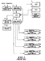
- Fig. 1 is a block diagram showing a control arrangement of a full-color printer equipped with a thermal line head for each ink of black, cyan, magenta, and yellow having ink ejection ports in a density of 600 dpi over a range of about 8 inches corresponding to a paper width when, for example, an A4-sized print paper is used to be fed in the longitudinal direction thereof.
- a reference numeral 1 denotes a CPU for executing operation control of the entire apparatus and data processing
- a reference numeral 2 denotes a ROM for storing control programs of the CPU 1, fonts, and various data for processing
- a reference numeral 3 denotes a RAM for used as a work area for processing of CPU 1 such as temporary storage of various data
- a reference numeral 4 denotes a data receiving unit for making communication control with external devices (not shown) such as a host computer to receive data from the external devices
- a reference numeral 5 denotes a DMA/RAM controller for performing DMA transfer of data from the data receiving portion 4 to the RAM 3, performing DMA transferring of image data stored in the RAM 3 to a line head controller 9, and controlling access of the RAM 3 by the CPU 1
- a reference numeral 6 denotes a non-volatile memory such as an EEPROM for storing parameters specific to the printer.
- Reference numerals 7K, 7C, 7M, and 7Y respectively denote thermal line heads for individually ejecting black (K), cyan (C), magenta (M), and yellow (Y) inks to a printing medium such as printing paper to print an image
- reference numerals 8K, 8C, 8M, an 8Y denote line head drivers for individually driving the thermal line heads 7K, 7C, 7M, and 7Y
- a reference numeral 9 denotes the line head controller for performing image data transferring to the individual line head drivers 8K, 8C, 8M, an 8Y, generating of heat pulse signals, and the like according to control signals from the CPU 1.
- a line feed motor driver 10 and a line feed motor 11 driven by the driver 10 perform rotation drive of a feed roller (not shown) according to control signals supplied from the CPU 1, thereby performing movement of the printing medium in a sub-scanning direction, that is, paper feed.
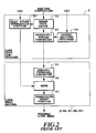
- Fig. 2 is a block diagram showing details of the line head controller 9 and the line head driver 8. For simplicity, the Figure shows only an arrangement for one color of ink.
- a reference numeral 91 denotes a heat pulse generation portion for generating pulses for driving the thermal line head in synchronization with the drive of the line feed motor
- a reference numeral 92 denotes an image data latch for receiving image data stored in the RAM 3 through the DMA/RAM controller 5 (see Fig.
- a reference numeral 93 denotes a parallel/serial converter for, to data from the image data latch 92, adding offset data relating to a beginning ejection port, that is, offset data from a reference ejection port to an end most ejection port whose data showing "ejection" in the ejection port row of the thermal line head, and thereafter performing parallel/serial conversion to serially transmit a serial data to the line head driver 8, and a reference numeral 94 denotes an offset setting register for setting the offset data relating to the beginning ejection port.
- a reference numeral 81 denotes a serial/parallel converter for performing serial/parallel conversion for the serial data
- a reference numeral 82 denotes a gate for performing OR operation between an output of the serial/parallel converter 81 and heat pulse from the heat pulse generation portion 91
- a reference numeral 83 denotes a transistor array for respectively supplying an electric current to an electro-thermal conversion element of the thermal line head according to an output of the gate 82.
- data inputted through the data receiving unit 4 is temporarily stored in the RAM 3 through the DMA/RAM controller 5, and an analysis of command, image data, character code is made by the CPU 1 according to a program stored in the ROM 2.
- the data stored in the RAM 3 is then converted into ejection data by the CPU 1, and sequentially stored in the RAM 3.
- the line feed motor 11 is driven by the line feed motor driver 10 and, at the same time, the eject data stored in the RAM 3 is transferred to the serial/parallel converter 81 of the line head driver 8 through the DMA/RAM controller 5 and the parallel/serial converter 93 of the thermal line head control unit 9.
- a heat pulse signal is sent from the heat pulse generation portion 91 of the line head controller 9 to the gate 82 of the line head driver 8, which switching drives the transistor array unit 83 to cause the electro-thermal conversion element of the corresponding ejection port of the thermal line head to generate heat energy, and the ink is ejected from the ejection port by bubbles produced thereby.
- the four thermal line heads 7K, 7C, 7M, and 7Y are arranged in the sub-scanning direction which is a feed direction of the printing paper. Therefore, it is necessary that the ejection data is transferred at a timing according to the distance between the individual thermal line heads in the sub-scanning direction with respect to the individual thermal line heads so that a plurality of ink dots is overlappedly formed at the same position on the paper.
- the spacing in the sub-scanning direction between the individual ejection ports of the individual thermal line heads is 1 inch and the resolution of dots formed in the sub-scanning direction is 600 dpi
- yellow and magenta are to be overlapped at a position to make red
- yellow is first ejected to form a dot
- the magenta ink ejected to form an overlapped dot the ejection data when ejecting magenta ink at the same time of ejecting the yellow ink must be data of 600 dots (600 rasters) before.
- a registration adjustment is a procedure for reducing a deviation of deposited position of ink droplets ejected by different thermal line heads to a small value or zero, and includes an adjustment in the sub-scanning direction and an adjustment in the main scanning direction which is the arrangement direction of the ejection ports.
- the deviation is not less than 1/2 the dot diameter, the image quality may be degraded.
- a cause of generation of deviation in the sub-scanning direction is a mounting error of the thermal line head or feeds fluctuation of printing medium.
- the deviation in the subscanning direction is adjusted by providing an adjustment mechanism in the mounting unit or by making ejection timing of each thermal line head variable.
- the cause of deviation in the main scanning direction is mainly a mounting error of the thermal line head, and the deviation can be adjusted by providing an adjustment mechanism in the mounting unit to adjust a portion of the ejection port of individual heads.
- the printable width of the individual thermal line heads that is, the arrangement width of the ejection ports is longer than a width required for printing, as shown in Fig. 3
- an offset can be adjusted for each head with respect to the beginning ejection port, thereby correcting a mounting error between individual thermal line heads to reduce deviation of registration.
- an exact adjustment of relative positions of the individual thermal line heads can be performed relatively easily at a delivery from the factory.
- temperature of the thermal line head may be changed due to a change in ambient temperature or printing operation.
- the thermal expansion coefficient of aluminum is about 2 ⁇ 10 -5 /°C
- the head length is increased at a rate of about 4 ⁇ m/°C in a printer for A4-sized paper.
- the individual thermal line heads are at the same temperature, since the relative positions in the main scanning direction are not changed, no problem occurs in the print quality.
- there is a temperature difference of more than 5.2°C the above described position deviation tolerance of 21 ⁇ m that can maintain the print quality is exceeded, resulting in considerable degradation in image quality.
- An object of the present invention is to provide a printing apparatus which can suppress deviation between dots formed by individual heads even when a difference in thermal expansion is generated by a temperature difference between individual print heads.
- Another object of the present invention is to provide a printing apparatus which can shift printing elements driven based on corresponding drive data of individual heads to each other even when a position deviation more than a predetermined value occurs between corresponding printing elements of the individual heads due to a difference in thermal expansion caused by a temperature difference between the individual heads, by inserting a dummy data into the drive data of the individual printing elements, thereby suppressing position deviation of dots formed according to the corresponding drive data to less than a predetermined value.
- a printing apparatus for performing printing on a printing medium, by using a plurality of print heads each having a plurality of printing elements arranged in a predetermined direction, comprising:
- a position deviation adjusting method of a print head in a printing apparatus using a plurality of the print heads each having a plurality of printing elements arranged in a predetermined direction and performing printing on a printing medium comprising the steps of:
- Fig. 4 is a block diagram showing a control arrangement of an ink jet printer according to an embodiment of the present invention
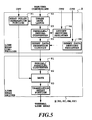
- Fig. 5 is a block diagram showing details of a line head controller 9 and a line head driver 8 shown in Fig. 4.
- a temperature sensor 12 is mounted close to each thermal line head 7, and an AD converter 13 is provided for converting an output from the temperature sensor 12 into a digital data to be supplied to a CPU 1. Then, data relating to temperature of each thermal line head can be obtained by means of the temperature sensor provided on each of the plurality of thermal line head. Further, as shown in Fig.
- the ink jet printer of the present embodiment is provided with a dummy data insertion circuit 95, which is disposed between a parallel/serial converter 93 of the line head controller 9 and a serial/parallel converter 81 of the line head driver 8, and a dummy data setting register 96 for setting whether or not the dummy data is inserted and for setting where the dummy data is inserted.
- the setting in the register 96 is controlled by the CPU 1.
- an electro-thermal conversion element is disposed to generate heat energy in an ink passage provided corresponding to each ink ejection port, and by applying a voltage pulse to the electro-thermal heat conversion element to drive, an air bubble is generated by utilizing the generated heat energy, and the ink is ejected by pressure of the bubble.
- the CPU 1 Periodically or after each completion of a predetermined operation in the printer, the CPU 1 detects outputs of temperature sensors 12K, 12C, 12M and 12Y as temperatures of the individual thermal line heads 7K, 7C, 7M, and 7Y through the AD converter 13.
- the temperature difference between any two thermal line heads is a temperature corresponding to a thermal expansion causing the deviation of, for example, greater than or equal to 1/2 pitch
- setting is performed in the dummy data setting register 96 corresponding to a lower temperature thermal line head so that a dummy data is inserted into data for the lower temperature thermal line head.
- Figs. 6A and 6B are schematic views for explaining details of dummy data insertion.
- the Figures show only two heads differing in temperature and differing in length changes thereof due to thermal expansion, and having 12 ejection ports.
- a number of ejection ports is not limited to this number, and when four heads are provided as in the present embodiment, in relation to the head of the largest thermal expansion, the dummy data is inserted into the data for the respective heads of smaller thermal expansion according to the respective length difference due to the thermal expansion as, described below.
- a shape of the ejection port is conveniently rectangular form, it is apparent that the shape of the ejection port is not limited to this form.
- eject data D1 to D12 corresponding to the individual ejection ports means data for ejecting/not ejecting the ink to the same positions on the printing medium, and it is apparent that the data of the same number among the individual heads does not always represent data of same content.
- Fig. 6A shows a case where lengths of the thermal heads differ from each other owing to thermal expansion difference caused by temperature difference between individual heads. More specifically, a deviation of greater than or equal to 1/2 pitch is produced in the seventh and succeeding ejection ports, which results in a deviation of greater than or equal to 1/2 pitch is produced in formed dots. That is, it is desirable that the dots formed by the ejection ports of the same number have no deviation, however, the dots formed by ejection ports after seventh port individually have deviations of greater than or equal to 1/2 pitch.
- a dummy data D6' is assigned to the seventh ejection port which begins to produce the deviation of greater than or equal to 1/2 pitch in the lower temperature line head, in place of the original ejection data D7. More specifically, the dummy data D6' is inserted between ejection data D6 and D7 by the dummy data insertion circuit 95. By this dummy data insertion, to No. 8 to No. 12 ejection ports in low temperature line head, ejection data D7 to D11 which are shifted by one ejection port unit are assigned, respectively.
- the respective dots formed by ink ejected the low temperature line head and the respective dots formed by ink ejected by the high temperature line head respectively based on ejection data D1 to D11 can all be overlapped with a deviation less than 1/2 pitch to each other. Thereby, degradation of image quality caused by position deviation of the corresponding ejection ports can be suppressed.
- the inserted dummy data D6' is set to data of "not ejection" in all cases, or the same as D6 of immediately before.
- No. 12 ejection port of the high temperature line head performs ejection based on data D12.
- a dummy data insertion position is determined as a position of the first ejection port where the expansion first becomes greater than or equal to 1/2 pitch, based on thermal expansion coefficient of the head and the head temperature as shown below.
- M 1/(2 ⁇ A ⁇ ⁇ T) here, M: ejection port number to which dummy data is assigned.
- the dummy data is assigned almost at a center in the ejection port arrangement.
- the dummy data insertion position is determined as follows.
- M n (2 ⁇ n - 1)/(2 ⁇ A ⁇ ⁇ T) here,
- the dummy data setting register 96 is necessary to have a plurality of registers for each head so that a plurality of ejection port positions can be set.
- a dummy data is inserted into driving data for individual printing elements according to each temperature of a plurality of print heads, even if a difference of thermal expansion due to temperature difference of individual heads is generated, and a position deviation greater than a predetermined value occurs in the corresponding printing elements between individual heads, the printing elements driven by corresponding driving data can be shifted between individual heads, thereby suppressing position deviation of dots formed according to the individual corresponding driver data to less than a predetermined value.
- an arrangement for obtaining the temperature of the thermal line head is not limited to the arrangement described in the above embodiment in which arrangement the temperature of each thermal line head is detected by means of the temperature sensor and control of the driving data is performed on a basis of the temperature detected.
- the temperature of the thermal line head may be estimated based on a number of driving data supplied to the printing element, a temperature of an environment and the like, and the control of the driving data may be performed on a basis of the temperature estimated.
Abstract
Description
- Fig. 1 is a block diagram showing a control arrangement of a prior art thermal line printer;
- Fig. 2 is a block diagram showing details of a line head driver and a line head controller of the thermal line printer shown in Fig. 1;
- Fig. 3 is a schematic view for explaining a registration adjustment between individual heads according to prior art;
- Fig. 4 is a block diagram showing a control arrangement of a thermal line printer according to an embodiment of the present invention;
- Fig. 5 is a block diagram showing details of a line head driver and a line head controller of the thermal line printer shown in Fig. 4;
- Figs. 6A and 6B are schematic views for explaining reduction of dot deviation by dummy data insertion according to an embodiment of the present invention.
- Mn:
- ejection port number to which n'th dummy data is assigned, n≥2; the dummy data is not assigned when Mn is greater than number of ejection ports of thermal line head.
Claims (14)
- A printing apparatus for performing printing on a printing medium, by using a plurality of print heads each having a plurality of printing elements arranged in a predetermined direction, characterized by comprising:head temperature data obtaining means for obtaining temperature data of each of the plurality of print heads;driving data supply means for supplying driving data for driving the plurality of printing elements of each of the plurality of print heads to said each of the plurality of print heads in accordance with an arrangement of said plurality of printing elements; anddummy data insertion means for inserting dummy data into the driving data supplied by said driving data supply means based on the temperature data of each of said plurality of print heads obtained by said head temperature data obtaining means.
- A printing apparatus as claimed in Claim 1, characterized in that said dummy data insertion means inserts the dummy data into the driving data in accordance with differences in thermal expansion between the plurality of print heads, said differences in thermal expansion corresponding to respective temperature data of said plurality of print heads.
- A printing apparatus as claimed in Claim 2, characterized in that, in relation to the print head of which temperature data is obtained as the highest temperature between the plurality of the print heads, said dummy data insertion means inserts the dummy data into the driving data for the print head of which temperature data is obtained as lower temperature than the highest temperature.
- A printing apparatus as claimed in Claim 3, characterized in that said dummy data insertion means inserts the dummy data into the driving data when the difference in thermal expansion calculated based on a temperature difference between the lower temperature and the highest temperature is greater than or equal to a predetermined value.
- A printing apparatus as claimed in Claim 4, characterized in that said dummy data insertion means inserts the dummy data as driving data for the printing element in the print head of the lower temperature, a deviation of a position of said printing element in the arrangement of the plurality of printing elements from a position of the corresponding printing element in the print head of the highest temperature first becoming a value greater than or equal to the predetermined value.
- A printing apparatus as claimed in Claim 5, characterized in that each of the plurality of print heads arranges a plurality of printing elements in accordance with a width of the printing medium fed.
- A printing apparatus as claimed in Claim 6, characterized in that the plurality of print heads perform printing of yellow, magenta, cyan, and black colors respectively.
- A printing apparatus as claimed in Claim 7, characterized in that said head temperature data obtaining means includes a temperature sensor provided on the plurality of print heads.
- A printing apparatus as claimed in Claim 8, characterized in that the plurality of print heads individually have an ink ejection port as a printing element, and an ink is ejected from said ink ejection port by a pressure of a bubble produced by utilizing heat energy.
- A printing apparatus as claimed in Claim 5, characterized in that each of the plurality of print heads have an excess printing element with respect to a width of an image to be printed, and said driving data supply means supplies the driving data shifted due to inserting of the dummy data as the driving data for said excess printing element.
- A printing apparatus as claimed in Claim 1, characterized in that the dummy data is a data indicating non-printing.
- A printing apparatus as claimed in Claim 1, characterized in that the dummy data is a data of the same content as the driving data adjacent to said dummy data.
- A position deviation adjusting method of a print head in a printing apparatus using a plurality of the print heads each having a plurality of printing elements arranged in a predetermined direction and performing printing on a printing medium, said method characterized by comprising the steps of:obtaining a temperature data of each of the plurality of print heads; andinserting a dummy data into a driving data supplied in accordance with arrangement of the plurality of printing elements and used for driving said plurality of printing elements, on a basis of temperature data obtained in each of the plurality of print heads.
- A printing apparatus or method wherein means are provided for modifying driving data for driving print elements of a print head by adding dummy data, which dummy data may be added for example in accordance with a detected temperature of the print head for suppressing deviation between dots printed by print heads having different thermal characteristics.
Applications Claiming Priority (3)
| Application Number | Priority Date | Filing Date | Title |
|---|---|---|---|
| JP20570496 | 1996-08-05 | ||
| JP205704/96 | 1996-08-05 | ||
| JP20570496A JP3368152B2 (en) | 1996-08-05 | 1996-08-05 | Printing apparatus and print head misalignment adjustment method |
Publications (3)
| Publication Number | Publication Date |
|---|---|
| EP0824243A2 true EP0824243A2 (en) | 1998-02-18 |
| EP0824243A3 EP0824243A3 (en) | 1999-03-17 |
| EP0824243B1 EP0824243B1 (en) | 2004-10-20 |
Family
ID=16511328
Family Applications (1)
| Application Number | Title | Priority Date | Filing Date |
|---|---|---|---|
| EP97305873A Expired - Lifetime EP0824243B1 (en) | 1996-08-05 | 1997-08-04 | Printing apparatus with registration of line print heads |
Country Status (4)
| Country | Link |
|---|---|
| US (1) | US5966149A (en) |
| EP (1) | EP0824243B1 (en) |
| JP (1) | JP3368152B2 (en) |
| DE (1) | DE69731263T2 (en) |
Cited By (3)
| Publication number | Priority date | Publication date | Assignee | Title |
|---|---|---|---|---|
| EP1020290A3 (en) * | 1999-01-13 | 2000-11-08 | Hewlett-Packard Company | Multiple printhead apparatus with temperature control and method |
| EP1120253A1 (en) * | 1999-03-10 | 2001-08-01 | Seiko Epson Corporation | Adjustment of displacement of dot forming position by using information that no dot is to be formed for each pixel unit |
| EP1537996A2 (en) | 2003-12-02 | 2005-06-08 | Canon Kabushiki Kaisha | Inkjet recording apparatus and method for controlling same |
Families Citing this family (7)
| Publication number | Priority date | Publication date | Assignee | Title |
|---|---|---|---|---|
| US6739687B1 (en) | 2002-10-31 | 2004-05-25 | Hewlett-Packard Development Company, L.P. | System and method for positioning print heads based on print job |
| JP2008044116A (en) * | 2006-08-10 | 2008-02-28 | Fuji Xerox Co Ltd | Printer, and compensating method |
| JP2008272973A (en) * | 2007-04-26 | 2008-11-13 | Fuji Xerox Co Ltd | Liquid droplet jet device and image forming apparatus having the same |
| JP6208973B2 (en) * | 2012-05-02 | 2017-10-04 | 株式会社小森コーポレーション | Sheet digital printing machine |
| JP6286971B2 (en) * | 2013-09-20 | 2018-03-07 | コニカミノルタ株式会社 | Inkjet recording device |
| JP2022073137A (en) | 2020-10-30 | 2022-05-17 | キヤノン株式会社 | Correction method of recording position, recording method, recording device, and program |
| JP2022073145A (en) | 2020-10-30 | 2022-05-17 | キヤノン株式会社 | Adjustment method of recording position |
Citations (4)
| Publication number | Priority date | Publication date | Assignee | Title |
|---|---|---|---|---|
| US4721969A (en) * | 1985-05-28 | 1988-01-26 | Olympus Optical Company, Ltd. | Process of correcting for color misregistering in electrostatic color recording apparatus |
| EP0512799A2 (en) * | 1991-05-10 | 1992-11-11 | Xerox Corporation | Pagewidth thermal ink jet printhead |
| EP0710921A2 (en) * | 1994-11-07 | 1996-05-08 | Canon Aptex Inc. | Printer |
| US5528272A (en) * | 1993-12-15 | 1996-06-18 | Xerox Corporation | Full width array read or write bars having low induced thermal stress |
Family Cites Families (1)
| Publication number | Priority date | Publication date | Assignee | Title |
|---|---|---|---|---|
| US4977410A (en) * | 1989-09-14 | 1990-12-11 | Seiko Instruments Inc. | Thermal line printer with staggered head segments and overlap compensation |
-
1996
- 1996-08-05 JP JP20570496A patent/JP3368152B2/en not_active Expired - Fee Related
-
1997
- 1997-08-01 US US08/904,866 patent/US5966149A/en not_active Expired - Fee Related
- 1997-08-04 DE DE69731263T patent/DE69731263T2/en not_active Expired - Fee Related
- 1997-08-04 EP EP97305873A patent/EP0824243B1/en not_active Expired - Lifetime
Patent Citations (4)
| Publication number | Priority date | Publication date | Assignee | Title |
|---|---|---|---|---|
| US4721969A (en) * | 1985-05-28 | 1988-01-26 | Olympus Optical Company, Ltd. | Process of correcting for color misregistering in electrostatic color recording apparatus |
| EP0512799A2 (en) * | 1991-05-10 | 1992-11-11 | Xerox Corporation | Pagewidth thermal ink jet printhead |
| US5528272A (en) * | 1993-12-15 | 1996-06-18 | Xerox Corporation | Full width array read or write bars having low induced thermal stress |
| EP0710921A2 (en) * | 1994-11-07 | 1996-05-08 | Canon Aptex Inc. | Printer |
Cited By (13)
| Publication number | Priority date | Publication date | Assignee | Title |
|---|---|---|---|---|
| US6641243B2 (en) | 1999-01-13 | 2003-11-04 | Hewlett-Packard Development Company, L.P. | Multiple printhead apparatus with temperature control and method |
| EP1020290A3 (en) * | 1999-01-13 | 2000-11-08 | Hewlett-Packard Company | Multiple printhead apparatus with temperature control and method |
| US6322189B1 (en) | 1999-01-13 | 2001-11-27 | Hewlett-Packard Company | Multiple printhead apparatus with temperature control and method |
| US6984011B2 (en) | 1999-03-10 | 2006-01-10 | Seiko Epson Corporation | Dot formation position misalignment adjustment performed using pixel-level information indicating dot non-formation |
| EP1120253A4 (en) * | 1999-03-10 | 2004-11-10 | Seiko Epson Corp | Adjustment of displacement of dot forming position by using information that no dot is to be formed for each pixel unit |
| EP1120253A1 (en) * | 1999-03-10 | 2001-08-01 | Seiko Epson Corporation | Adjustment of displacement of dot forming position by using information that no dot is to be formed for each pixel unit |
| EP1681165A2 (en) * | 1999-03-10 | 2006-07-19 | Seiko Epson Corporation | Dot formation position misalignment adjustment performed using pixel-level information indicating dot non-formation |
| EP1681164A2 (en) * | 1999-03-10 | 2006-07-19 | Seiko Epson Corporation | Dot formation position misalignment adjustment performed using pixel-level information indicating dot non-formation |
| EP1681165A3 (en) * | 1999-03-10 | 2009-04-01 | Seiko Epson Corporation | Dot formation position misalignment adjustment performed using pixel-level information indicating dot non-formation |
| EP1681164A3 (en) * | 1999-03-10 | 2009-04-01 | Seiko Epson Corporation | Dot formation position misalignment adjustment performed using pixel-level information indicating dot non-formation |
| EP1537996A2 (en) | 2003-12-02 | 2005-06-08 | Canon Kabushiki Kaisha | Inkjet recording apparatus and method for controlling same |
| EP1537996A3 (en) * | 2003-12-02 | 2007-09-05 | Canon Kabushiki Kaisha | Inkjet recording apparatus and method for controlling same |
| US7857412B2 (en) | 2003-12-02 | 2010-12-28 | Canon Kabushiki Kaisha | Inkjet recording apparatus and method for controlling same |
Also Published As
| Publication number | Publication date |
|---|---|
| DE69731263T2 (en) | 2006-02-23 |
| EP0824243A3 (en) | 1999-03-17 |
| EP0824243B1 (en) | 2004-10-20 |
| JP3368152B2 (en) | 2003-01-20 |
| US5966149A (en) | 1999-10-12 |
| JPH1044423A (en) | 1998-02-17 |
| DE69731263D1 (en) | 2004-11-25 |
Similar Documents
| Publication | Publication Date | Title |
|---|---|---|
| US6371588B1 (en) | Printhead and printing apparatus using printhead | |
| US6554387B1 (en) | Misregistration correction for bidirectional printing in consideration of inclination of nozzle array | |
| EP0679518A1 (en) | Print head, especially for use in a serial printer | |
| JP3567798B2 (en) | Printing apparatus, printing method, and recording medium | |
| US5966149A (en) | Printing apparatus in which registration adjustment between a plurality of print heads is performed | |
| US20020067393A1 (en) | Ink-jet printing apparatus and ink-jet printing method | |
| EP0842781A2 (en) | Ink-jet printing apparatus and ink-jet printing method for reducing density unevenness in a printed image due to deviation of ink application position | |
| US20110304666A1 (en) | Inkjet printing apparatus and inkjet printing method | |
| US7850268B2 (en) | Recording method and recording apparatus | |
| JP4632388B2 (en) | Printing apparatus and printing method | |
| JP4885803B2 (en) | Printing method of substrate | |
| JP2017217823A (en) | Recording head, recording device and temperature retaining control method for recording head | |
| US6092888A (en) | Method of transmitting raster information from a host computer to an ink jet printer and corresponding method of printing | |
| US6793304B2 (en) | Printing apparatus | |
| JP2012125981A (en) | Ink ejection head controller, image forming apparatus, ink ejection head control method, and program | |
| US7306306B2 (en) | Inkjet recording method and inkjet recording apparatus | |
| EP1127697B1 (en) | Current supply control method for line thermal head | |
| US7036897B2 (en) | Method and apparatus for operating a printer | |
| US7306314B2 (en) | Recording apparatus and recording control method | |
| JP3293707B2 (en) | Ink jet recording device | |
| US7635172B2 (en) | Recording apparatus and method for rearranging recording data in accordance with recording head tilt | |
| JP6237195B2 (en) | Printing method and printing apparatus | |
| JPH1044474A (en) | Color registration adjusting method and color printer | |
| JP6171915B2 (en) | Printing method and printing apparatus | |
| JP2000238249A (en) | Ink jet recording apparatus |
Legal Events
| Date | Code | Title | Description |
|---|---|---|---|
| PUAI | Public reference made under article 153(3) epc to a published international application that has entered the european phase |
Free format text: ORIGINAL CODE: 0009012 |
|
| AK | Designated contracting states |
Kind code of ref document: A2 Designated state(s): DE ES FR GB IT NL |
|
| AX | Request for extension of the european patent |
Free format text: AL;LT;LV;RO;SI |
|
| PUAL | Search report despatched |
Free format text: ORIGINAL CODE: 0009013 |
|
| AK | Designated contracting states |
Kind code of ref document: A3 Designated state(s): AT BE CH DE DK ES FI FR GB GR IE IT LI LU MC NL PT SE |
|
| AX | Request for extension of the european patent |
Free format text: AL;LT;LV;RO;SI |
|
| 17P | Request for examination filed |
Effective date: 19990730 |
|
| AKX | Designation fees paid |
Free format text: DE ES FR GB IT NL |
|
| 17Q | First examination report despatched |
Effective date: 20020502 |
|
| GRAP | Despatch of communication of intention to grant a patent |
Free format text: ORIGINAL CODE: EPIDOSNIGR1 |
|
| GRAS | Grant fee paid |
Free format text: ORIGINAL CODE: EPIDOSNIGR3 |
|
| GRAA | (expected) grant |
Free format text: ORIGINAL CODE: 0009210 |
|
| AK | Designated contracting states |
Kind code of ref document: B1 Designated state(s): DE ES FR GB IT NL |
|
| PG25 | Lapsed in a contracting state [announced via postgrant information from national office to epo] |
Ref country code: NL Free format text: LAPSE BECAUSE OF FAILURE TO SUBMIT A TRANSLATION OF THE DESCRIPTION OR TO PAY THE FEE WITHIN THE PRESCRIBED TIME-LIMIT Effective date: 20041020 |
|
| REG | Reference to a national code |
Ref country code: GB Ref legal event code: FG4D |
|
| REF | Corresponds to: |
Ref document number: 69731263 Country of ref document: DE Date of ref document: 20041125 Kind code of ref document: P |
|
| PG25 | Lapsed in a contracting state [announced via postgrant information from national office to epo] |
Ref country code: ES Free format text: LAPSE BECAUSE OF FAILURE TO SUBMIT A TRANSLATION OF THE DESCRIPTION OR TO PAY THE FEE WITHIN THE PRESCRIBED TIME-LIMIT Effective date: 20050131 |
|
| NLV1 | Nl: lapsed or annulled due to failure to fulfill the requirements of art. 29p and 29m of the patents act | ||
| PLBE | No opposition filed within time limit |
Free format text: ORIGINAL CODE: 0009261 |
|
| STAA | Information on the status of an ep patent application or granted ep patent |
Free format text: STATUS: NO OPPOSITION FILED WITHIN TIME LIMIT |
|
| ET | Fr: translation filed | ||
| 26N | No opposition filed |
Effective date: 20050721 |
|
| PGFP | Annual fee paid to national office [announced via postgrant information from national office to epo] |
Ref country code: GB Payment date: 20060821 Year of fee payment: 10 |
|
| PGFP | Annual fee paid to national office [announced via postgrant information from national office to epo] |
Ref country code: FR Payment date: 20060825 Year of fee payment: 10 |
|
| PGFP | Annual fee paid to national office [announced via postgrant information from national office to epo] |
Ref country code: IT Payment date: 20060831 Year of fee payment: 10 |
|
| PGFP | Annual fee paid to national office [announced via postgrant information from national office to epo] |
Ref country code: DE Payment date: 20061018 Year of fee payment: 10 |
|
| GBPC | Gb: european patent ceased through non-payment of renewal fee |
Effective date: 20070804 |
|
| REG | Reference to a national code |
Ref country code: FR Ref legal event code: ST Effective date: 20080430 |
|
| PG25 | Lapsed in a contracting state [announced via postgrant information from national office to epo] |
Ref country code: DE Free format text: LAPSE BECAUSE OF NON-PAYMENT OF DUE FEES Effective date: 20080301 |
|
| PG25 | Lapsed in a contracting state [announced via postgrant information from national office to epo] |
Ref country code: FR Free format text: LAPSE BECAUSE OF NON-PAYMENT OF DUE FEES Effective date: 20070831 |
|
| PG25 | Lapsed in a contracting state [announced via postgrant information from national office to epo] |
Ref country code: GB Free format text: LAPSE BECAUSE OF NON-PAYMENT OF DUE FEES Effective date: 20070804 |
|
| PG25 | Lapsed in a contracting state [announced via postgrant information from national office to epo] |
Ref country code: IT Free format text: LAPSE BECAUSE OF NON-PAYMENT OF DUE FEES Effective date: 20070804 |